EP2560149A2 - Bildverarbeitungsvorrichtung, Bildverarbeitungsverfahren und Programm - Google Patents
Bildverarbeitungsvorrichtung, Bildverarbeitungsverfahren und Programm Download PDFInfo
- Publication number
- EP2560149A2 EP2560149A2 EP12179626A EP12179626A EP2560149A2 EP 2560149 A2 EP2560149 A2 EP 2560149A2 EP 12179626 A EP12179626 A EP 12179626A EP 12179626 A EP12179626 A EP 12179626A EP 2560149 A2 EP2560149 A2 EP 2560149A2
- Authority
- EP
- European Patent Office
- Prior art keywords
- blocks
- image
- histogram
- determination
- normalization
- Prior art date
- Legal status (The legal status is an assumption and is not a legal conclusion. Google has not performed a legal analysis and makes no representation as to the accuracy of the status listed.)
- Withdrawn
Links
Images


Classifications
-
- G—PHYSICS
- G08—SIGNALLING
- G08B—SIGNALLING OR CALLING SYSTEMS; ORDER TELEGRAPHS; ALARM SYSTEMS
- G08B29/00—Checking or monitoring of signalling or alarm systems; Prevention or correction of operating errors, e.g. preventing unauthorised operation
- G08B29/02—Monitoring continuously signalling or alarm systems
- G08B29/04—Monitoring of the detection circuits
- G08B29/046—Monitoring of the detection circuits prevention of tampering with detection circuits
-
- G—PHYSICS
- G08—SIGNALLING
- G08B—SIGNALLING OR CALLING SYSTEMS; ORDER TELEGRAPHS; ALARM SYSTEMS
- G08B13/00—Burglar, theft or intruder alarms
- G08B13/18—Actuation by interference with heat, light, or radiation of shorter wavelength; Actuation by intruding sources of heat, light, or radiation of shorter wavelength
- G08B13/189—Actuation by interference with heat, light, or radiation of shorter wavelength; Actuation by intruding sources of heat, light, or radiation of shorter wavelength using passive radiation detection systems
- G08B13/194—Actuation by interference with heat, light, or radiation of shorter wavelength; Actuation by intruding sources of heat, light, or radiation of shorter wavelength using passive radiation detection systems using image scanning and comparing systems
- G08B13/196—Actuation by interference with heat, light, or radiation of shorter wavelength; Actuation by intruding sources of heat, light, or radiation of shorter wavelength using passive radiation detection systems using image scanning and comparing systems using television cameras
- G08B13/19602—Image analysis to detect motion of the intruder, e.g. by frame subtraction
Definitions
- the present technology relates to an image processing device, an image processing method and a program. More specifically, the present technology relates to an image processing device, an image processing method and a program that can detect an act of sabotage committed on a surveillance camera or the like.
- a surveillance system in which, in order to detect an intruder, such as a person or an animal, in a specific space, images are captured of a targeted space by a surveillance camera, and the intruder is detected from the captured images.
- an act of sabotage is committed, such as covering the surveillance camera with a cloth, changing an orientation of the surveillance camera or spraying a lens of the surveillance camera, it is no longer possible to perform surveillance.
- Japanese Patent No. 04626632 and Japanese Patent No. 04227539 it is possible to detect that there has been an act of sabotage. However, it is difficult to determine the type of sabotage. By making it possible to determine the type of sabotage, a response to resolve the sabotage is different, and it is therefore preferable to be able to determine the type of sabotage in addition to detection.
- processing is disclosed that also includes moving body detection processing to inhibit mistaken detection due to a moving body.
- detection is not possible except in such a scenario as when the moving body covers a whole screen, and it is difficult to perform detection with respect to a more detailed situation.
- the present technology has been devised in light of the foregoing circumstances and makes it possible to accurately detect sabotage that is committed against a surveillance camera or the like, and that further makes it possible to determine the type of the sabotage.
- an image processing device including: an acquisition portion that acquires image data of an image; a dividing portion that divides the acquired image into a number of blocks N (N > 1); a specification portion that sequentially specifies, each time the image data of the image is newly acquired, a number of the blocks M (N ⁇ M > 1) from among the number of the blocks N, as the blocks to be updated; a filtering portion that performs filtering using a predetermined filter on the image data of the specified number of the blocks M; a counting portion that counts a number of pixels for which a filtering result is larger than a predetermined value; a first determination portion that determines whether there is an abnormality in the blocks, by comparing the number of the pixels counted by the counting portion with a predetermined value; and a second determination portion that determines whether sabotage has occurred, by comparing, with a predetermined value, a number of the blocks within the image that are determined by the first determination portion to have an abnormality.
- the counting portion may calculate an average value by dividing a sum value of the number of pixels obtained by counting the number of the pixels for which the filtering result is larger than the predetermined value, and a value of pixels for which it is determined that the filtering result is equal to or larger than the predetermined value, by the number of pixels.
- the first determination portion may perform a first determination that determines whether the number of pixels is smaller than a predetermined value, and a second determination that determines whether the average value is smaller than a predetermined value, and may set a logical sum of the first determination and the second determination as a determination result.
- the image processing device may further include: a histogram generation portion that generates a histogram of the image data of each of the specified number of the blocks M; a histogram storage portion that sequentially updates and stores the generated histogram; a change determination portion that, based on a degree of similarity between the generated histogram of each of the specified number of the blocks M and the corresponding stored past histogram of the number of the blocks M, determines whether there is a change in the acquired image; a normalization determination portion that determines whether to perform normalization of the histogram; and a normalization portion that, when it is determined by the normalization determination portion that normalization is to be performed, performs normalization of one of the generated histogram of the number of the blocks M or the corresponding stored past histogram of the number of the blocks M.
- the change determination portion may determine whether there is a change in the acquired image based on a degree of similarity using the normalized histogram, and may determine that sabotage has occurred when it is determined that there is a change.
- a determination result by the second determination portion and a determination result by the change determination portion may be integrated and a type of the sabotage may be determined.
- an image processing method which includes: acquiring image data of an image; dividing the acquired image into a number of blocks N (N > 1); sequentially specifying, each time the image data of the image is newly acquired, a number of the blocks M (N ⁇ M > 1) from among the number of the blocks N, as the blocks to be updated; performing filtering using a predetermined filter on the image data of the specified number of the blocks M; counting a number of pixels for which a filtering result is larger than a predetermined value; determining whether there is an abnormality in the blocks, by comparing the counted number of the pixels with a predetermined value; and determining whether sabotage has occurred, by comparing, with a predetermined value, a number of the blocks within the image that are determined to have an abnormality.
- a computer-readable program including instructions that command a computer to perform: acquiring image data of an image; dividing the acquired image into a number of blocks N (N > 1); sequentially specifying, each time the image data of the image is newly acquired, a number of the blocks M (N ⁇ M > 1) from among the number of the blocks N, as the blocks to be updated; performing filtering using a predetermined filter on the image data of the specified number of the blocks M; counting a number of pixels for which a filtering result is larger than a predetermined value; determining whether there is an abnormality in the blocks, by comparing the counted number of the pixels with a predetermined value; and determining whether sabotage has occurred, by comparing, with a predetermined value, a number of the blocks within the image that are determined to have an abnormality.
- an acquired image is divided into a number of blocks N (N > 1), and each time the image data of the image is newly acquired, a number of the blocks M (N ⁇ M > 1) from among the number of the blocks N is sequentially specified as the blocks to be updated.
- Filtering is performed, using a predetermined filter, on the image data of the specified number of the blocks M, and a number of pixels for which a filtering result is larger than a predetermined value is counted.
- the counted number of the pixels is compared with a predetermined value and thus it is determined whether there is an abnormality in the blocks.
- a number of the blocks within the image that are determined to have an abnormality is further compared with a predetermined value and it is thus determined whether sabotage has occurred.
- the sabotage when an act of sabotage is committed against a surveillance camera or the like, the sabotage can be accurately detected. Further, the type of the sabotage can be determined. By making it possible to determine the type of the sabotage, it is easy for a user to take appropriate action to resolve the sabotage.
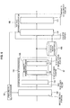
- FIG. 1 is a block diagram showing a configuration of an image processing device according to an embodiment of the present technology.
- the present technology is applied to a device that analyzes an image captured by a surveillance camera and detects sabotage committed against the surveillance camera.
- An image processing device 11 shown in FIG. 1 detects an act of sabotage against a surveillance camera (surveillance device) based on the captured image, and outputs an alarm when the act of sabotage is detected.
- surveillance camera surveillance camera
- Sabotage against the surveillance camera includes sabotage in which a surveillance target is removed from a field of view (such that it is outside a range of capture).
- This type of sabotage includes "turning” in which an orientation of the surveillance camera is changed, and "covering” in which the surveillance camera is covered with a cloth or the like.
- this type of sabotage, in which the surveillance target is removed from the field of view is referred to as a global change.
- This type of sabotage includes "focus blurring” in which the focus of the surveillance camera is changed, and “zoom blurring” in which the zoom of the surveillance camera is put out of focus.
- This type of sabotage, in which the focus is changed, is referred to here as defocus or defocusing.
- the image processing device 11 shown in FIG. 1 includes an acquisition portion 21 and an image processing portion 22.
- the acquisition portion 21 is a unit that acquires image data of an image.
- the acquisition portion 21 has a built-in complementary metal oxide semiconductor (CMOS) sensor and an imaging portion, such as a video camera, and acquires and outputs image data obtained by capturing images of a subj ect, such as a target space, that is under surveillance by the imaging portion.
- CMOS complementary metal oxide semiconductor
- the acquisition portion 21 can also acquire image data supplied from an external source via a network.
- the image processing portion 22 includes an imaging signal processing portion 31, a data storage portion 32 and an image analysis portion 33.
- the imaging signal processing portion 31 performs various types of image processing on the image data acquired by the acquisition portion 21, such as black level correction processing, white balance processing, gamma correction processing and color correction processing.
- the imaging signal processing portion 31 is, for example, a digital signal processor (DSP).
- the data storage portion 32 stores the image data processed by the imaging signal processing portion 31.
- the data storage portion 32 is, for example, a random access memory (RAM).
- the image analysis portion 33 detects an act of sabotage by analyzing a current image supplied from the imaging signal processing portion 31 and a reference image that is a past image supplied from the data storage portion 32.
- the image analysis portion 33 is, for example, a central processing unit (CPU).
- FIG. 2 is a diagram showing an internal configuration of the image analysis portion 33.
- the image analysis portion 33 includes a global change detection portion 41, a defocus detection portion 42 and a detection result integration portion 43.
- the global change detection portion 41 performs processing that detects the above-described global change sabotage.
- the defocus detection portion 42 performs processing that detects the above-described defocusing sabotage.
- the detection result integration portion 43 integrates detection results respectively output from the global change detection portion 41 and the defocus detection portion 42, and determines the type of the act of sabotage against the surveillance camera.
- FIG. 3 is a block diagram showing an example of a detailed configuration of the global change detection portion 41.
- the global change detection portion 41 includes an update region selection portion 61, a histogram storage portion 62, an image dividing portion 63, a histogram generation portion 64, a normalization processing portion 65, a change determination portion 66, a changed region storage portion 67, a counter portion 68 and a threshold determination portion 69.
- the update region selection portion 61 functions as a specifying unit that sequentially specifies, each time image data of a new image is acquired, a number of blocks M from among a number of blocks N (N ⁇ M > 1) as blocks to be updated. From data supplied from the imaging signal processing portion 31, the update region selection portion 61 extracts a frame number of an image acquired by the acquisition portion 21 and decides a frame number to be updated. Further, the update region selection portion 61 decides a block to be updated in the frame to be updated.
- the image dividing portion 63 is a unit that divides the acquired image into the number of blocks N (N > 1). Of the images of each frame based on the image data supplied from the imaging signal processing portion 31, the image dividing portion 63 divides the frame specified by the update region selection portion 61 into a plurality of blocks. The image dividing portion 63 further, of the divided blocks, supplies to the histogram generation portion 64 image data of the blocks specified by the update region selection portion 61.
- the histogram generation portion 64 is a histogram generating unit that generates a histogram of the acquired image data, and generates a histogram of each of the blocks supplied from the image dividing portion 63. Note that sometimes the imaging signal processing portion 31 is provided with a histogram generating function. In this case, the histogram generation portion 64 can be provided inside the imaging signal processing portion 31.
- the histogram storage portion 62 is a histogram storage unit that sequentially updates and stores the generated histogram, and updates the histogram of each of the blocks specified as an update region by the update region selection portion 61. Specifically, a histogram of a block corresponding to a past frame that is already stored is overwritten by a histogram of an update target block of a current frame supplied from the histogram generation portion 64.
- the normalization processing portion 65 normalizes the histogram of each of the blocks as necessary.
- the histogram generation portion 64 supplies the histogram of each of the update target blocks of the current frame to the normalization processing portion 65. Further, the histogram storage portion 62 supplies to the normalization processing portion 65 the past histogram corresponding to each of the blocks supplied from the histogram generation portion 64.
- the normalization processing portion 65 determines whether or not it is necessary to normalize the histogram relating to each of the update target blocks of the current frame supplied from the histogram generation portion 64, and performs normalization as necessary. It should be noted that a determination as to whether the histogram of the update target block of the current frame is normalized or the histogram of the corresponding past block is normalized is performed in accordance with a condition of the histograms.
- the change determination portion 66 is a change determination unit that determines a change of the acquired image.
- the change determination portion 66 performs change determination processing based on a degree of similarity between the generated current histogram and the stored past histogram.
- the change determination portion 66 includes a degree of similarity calculation portion 71 and a threshold determination portion 72.
- the degree of similarity calculation portion 71 functions as a degree of similarity calculation unit that calculates a degree of similarity between the current histogram and the past histogram. Specifically, the degree of similarity calculation portion 71 calculates the degree of similarity between the histogram of each of the update target blocks of the current frame supplied from the histogram generation portion 64 and the histogram of each of the corresponding past blocks.
- the threshold determination portion 72 is a unit that determines a degree of similarity threshold value.
- the threshold determination portion 72 compares the calculated degree of similarity with the degree of similarity threshold value and determines, when the degree of similarity is larger than the degree of similarity threshold value, whether or not there has been a change in the image of the blocks.
- the threshold determination portion 72 outputs a determination result with respect to changes of the image of the blocks (presence or absence of change) to the changed region storage portion 67 and the counter portion 68.
- the changed region storage portion 67 stores the result of the determination by the change determination portion 66. Specifically, the presence or absence of change in the update target block of the current frame with respect to the past block is sequentially stored in the changed region storage portion 67 each time the image data of the new image is acquired.
- the counter portion 68 is a counting unit that counts a number of the blocks in which it is determined that there has been a change.
- the change determination portion 66 supplies the determination result (the presence or absence of change) of the update target blocks of the current frame to the counter portion 68.
- the changed region storage portion 67 supplies a determination result of blocks other than the update target blocks of the current frame to the counter portion 68. Based on the output of the change determination portion 66 and on the output of the changed region storage portion 67, the counter portion 68 counts the number of the blocks within a single image under surveillance in which there has been a change.
- the threshold determination portion 69 is an alarm threshold determination unit that compares the counted value with an alarm threshold value and that outputs an alarm when the counted value is larger than the alarm threshold value.
- the threshold determination portion 69 compares the number of blocks counted by the counter portion 68 with a predetermined threshold value that is set in advance. When the counted number of blocks is larger than the threshold value, it is determined that an act of sabotage has been detected, and a detection signal is output.
- the detection signal can be, for example, an alarm.
- FIG. 4 is a block diagram showing a detailed configuration example of the normalization processing portion 65.
- the normalization processing portion 65 includes a normalization determination portion 81, a normalization value calculation portion 82, an average value storage portion 83 and a normalization portion 84.
- the histogram of each of the update target blocks of the current frame is supplied to the normalization determination portion 81 from the histogram generation portion 64, and the past histogram corresponding to each of the blocks supplied from the histogram generation portion 64 is supplied to the normalization determination portion 81 from the histogram storage portion 62.
- the histogram of each of the update target blocks of the current frame is referred to as a current histogram and the histogram of each of the corresponding blocks of the past frame is referred to as a past histogram.
- the normalization determination portion 81 determines whether or not to perform normalization of the histogram of each of the update target block of the current frame. When the normalization determination portion 81 determines that normalization will not be performed (is not necessary), the current histogram and past histogram of each of the input update target blocks are supplied to the change determination portion 66 without change. When the normalization determination portion 81 determines that normalization will be performed (is necessary), the current histogram and the past histogram of each of the input update target blocks are supplied to the normalization value calculation portion 82.
- the normalization value calculation portion 82 calculates, from the current histogram and the past histogram of each of the input update target blocks, a normalization value to be used in the normalization.
- the calculated normalization value is supplied to the normalization portion 84, along with the current histogram and the past histogram of each of the input update target blocks.
- the average value storage portion 83 stores a direction of change and a rate of change of an average value of a histogram for each of the blocks other than the update target blocks, the average value of the histogram being calculated before the current frame. Further, a similar value that has been calculated by the normalization determination portion 81 and by the normalization value calculation portion 82 with respect to the current frame is supplied to and stored in (namely, it is updated in) the average value storage portion 83 in order to be used in processing from a next frame onwards.
- the values stored in the average value storage portion 83 (the direction of change and the rate of change of the average value of the histogram) will be explained in more detail later.
- the normalization portion 84 Based on the normalization value calculated by the normalization value calculation portion 82, the normalization portion 84 normalizes one of either the current histogram or the past histogram of each of the update target blocks. In this way, using the current histogram and the past histogram, it is possible to generate a histogram for which brightness of the blocks has been corrected.
- the normalization portion 84 outputs the current histogram and the past histogram after normalization to the change determination portion 66.
- the normalization determination portion 81 by providing the normalization determination portion 81 and determining whether or not to perform normalization as described above (and as will be described below), overall performance can be improved.
- a configuration is also possible in which the normalization determination portion 81 is not provided, calculation of the normalization value is performed by the normalization value calculation portion 82 with respect to all regions and normalization is performed by the normalization portion 84.
- the normalization processing portion 65 can be configured by the normalization value calculation portion 82 and the normalization portion 84.
- FIG. 5 is a block diagram showing a detailed configuration example of the defocus detection portion 42.
- the defocus detection portion 42 includes an update region selection portion 101, an image dividing portion 102, an abnormal region detection portion 103, a high frequency filter 104, an abnormality determination portion 105, an edge strength counter 106, a threshold determination portion 107, an abnormal region storage portion 108, a sabotage determination portion 109, a counter portion 110 and a threshold determination portion 111.
- the update region selection portion 101 functions as a specifying unit that sequentially specifies, each time image data of a new image is acquired, a number of blocks M from among a number of blocks N (N ⁇ M > 1) as blocks to be updated. From data supplied from the imaging signal processing portion 31, the update region selection portion 101 extracts a frame number of an image acquired by the acquisition portion 21 and decides a frame number to be updated. Further, the update region selection portion 101 decides a block to be updated in the frame to be updated.
- the image dividing portion 102 is a dividing unit that divides the acquired image into the number of blocks N (N > 1). Of the images of each frame based on the image data supplied from the imaging signal processing portion 31, the image dividing portion 102 divides the frame specified by the update region selection portion 101 into a plurality of blocks. Further, the image dividing portion 102 supplies, of the divided blocks, image data of the blocks specified by the update region selection portion 101 to the high frequency filter 104 of the abnormal region detection portion 103.
- the high frequency filter 104 is a filtering unit that performs filtering by a high frequency filter on the acquired image data.
- the high frequency filter 104 executes filtering processing by a predetermined high frequency filter on the blocks supplied from the image dividing portion 102.
- the abnormality determination portion 105 is an abnormality determining unit that determines an abnormality of the acquired image.
- the abnormality determination portion 105 includes the edge strength counter 106 and the threshold determination portion 107.
- the edge strength counter 106 functions as a calculation unit that counts a number of pixels whose edge strength is greater than a predetermined threshold value and calculates an edge strength average value etc.
- the threshold determination portion 107 is an alarm threshold determination unit.
- the threshold determination portion 107 compares a number of pixels and an average value etc. with predetermined threshold values, and determines that an abnormality exists in an image of a block having larger than the threshold values.
- the threshold determination portion 107 outputs a determination result (the presence or absence of an abnormality) regarding an abnormality of the image of the block to the abnormal region storage portion 108 and to the counter portion 110.
- the abnormal region storage portion 108 stores the result of the determination by the abnormality determination portion 105. Specifically, the presence or absence of an abnormality in the update target block of the current frame with respect to the past block is sequentially stored in the abnormal region storage portion 108 each time the image data of the new image is acquired.
- the sabotage determination portion 109 includes the counter portion 110 and the threshold determination portion 111.
- the sabotage determination portion 109 determines whether or not there has been an act of sabotage against the surveillance camera.
- the counter portion 110 is a counting unit that counts a number of the blocks in which it is determined that there has been an abnormality.
- the abnormality determination portion 105 supplies the determination result (the presence or absence of an abnormality) of the update target block of the current frame to the counter portion 110. Further, the abnormal region storage portion 108 supplies a determination result of the blocks other than the update target block of the current frame to the counter portion 110. Based on the output of the abnormality determination portion 105 and on the output of the abnormal region storage portion 108, the counter portion 110 counts the number of blocks within a single image under surveillance in which there has been an abnormality.
- the threshold determination portion 111 is an alarm threshold determination unit that compares the counted value with an alarm threshold value and that outputs an alarm when the counted value is larger than the alarm threshold value.
- the threshold determination portion 111 compares the number of blocks counted by the counter portion 110 with a predetermined threshold value that is set in advance. When the counted number of blocks is larger than the threshold value, it is determined that an act of sabotage has been detected, and a detection signal is output.
- the detection signal can be, for example, an alarm.
- these detection portions can respectively detect the global change sabotage relating and the defocusing sabotage.
- processing performed, respectively, by the global change detection portion 41 and by the defocus detection portion 42 will be explained. First, the explanation will be made with respect to the global change detection portion 41.
- the global change detection portion 41 acquires, respectively, a past image PI and a current image NI, divides each of the past image PI and the current image NI into blocks of a predetermined size, and calculates a histogram of pixel values for each block. Then, a degree of similarity is calculated between a histogram of a block in a predetermined position of the past image PI and a histogram of a block in a corresponding position of the current image NI.
- Blocks with a low degree of similarity are detected as a changed region VI, and when a number of the changed regions VI is large, it is determined that there has been an act of sabotage. In this case, an alarm is output.
- processing performed here by blocks that configure the global change detection portion 41 will be explained.
- the normalization determination portion 81 is supplied with the current histogram and the past histogram of each of the update target blocks of the current frame.
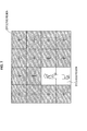
- the image is divided into 16 blocks, and 4 blocks shaded by oblique lines indicate the update target blocks of the current frame.
- the normalization determination portion 81 calculates an average value of each of the current histogram and the past histogram for each of the update target blocks of the current frame, and determines whether a direction of change of the average values from the past to the current time is an increase, a decrease or no change. For example, if a difference (an absolute value) between the average values of the past and the current histograms is within a predetermined range TH, it can be determined that there is no change. If the difference is greater than the predetermined range TH, it can be determined that there is an increase or a decrease depending on the direction of change.
- the normalization determination portion 81 acquires, from the average value storage portion 83, a determination result (the direction of change) of a similar determination with respect to the blocks that are not the update target blocks of the current frame. Then, the normalization determination portion 81 determines, as a change of the whole screen, whether there has been an increase, a decrease or no change. For example, if the number of blocks in which there has been an increase (decrease) with respect to the number of blocks of the whole screen is equal to or larger than a predetermined ratio that has been set in advance, it can be determined that the change is that of an increase (decrease) for the whole screen.
- blocks assigned with a plus (+) sign indicate blocks for which the direction of change is an increase
- blocks assigned with a minus (-) sign indicate blocks for which the direction of change is a decrease
- Blocks that are not assigned with a sign indicate blocks for which there is no change. For the frame shown on the right side in FIG. 6 , it is determined for the whole screen that this is a frame in which a change of increase has been seen.
- the normalization determination portion 81 determines that it is necessary to perform normalization.
- the normalization determination portion 81 determines that normalization is not necessary.
- the normalization value calculation portion 82 calculates a rate of change (hereinafter referred to as a change rate) that represents, for the whole screen, to what degree change has occurred.
- a change rate a rate of change
- the normalization value calculation portion 82 calculates the respective average values of the current histogram and the past histogram. For each of the update target blocks of the current frame, the normalization value calculation portion 82 calculates the average value from the supplied histogram. The average values of the current histogram and the past histogram of the blocks other than the update target blocks of the current frame are acquired from the average value storage portion 83, where they have already been calculated and stored.
- the normalization value calculation portion 82 decides an effective region from the whole screen.
- each region of the blocks in which the direction of change is the increase is set as the effective region.
- the normalization value calculation portion 82 divides the average value of the current histogram by the average value of the past histogram and sets a resulting value as the change rate. In this way, the change rate is calculated for each of the blocks set as the effective region.
- each of the regions of the blocks in which the direction of change is the increase is set as the effective region.
- blocks for which a rate of increase is equal to or larger than a predetermined value namely, blocks which have become extremely bright, are also removed from the effective region.
- the blocks for which there has been no change, the blocks for which the direction of change of the average value is a decrease, and the blocks which have become extremely bright are removed from the effective region because in this case there is a high probability that a moving body is present that has caused a change in brightness by the AE function.
- the blocks shaded by oblique lines are blocks that are set as the effective region.
- each region of the blocks in which the direction of change is the decrease is set as the effective region. Then, for each of the blocks set as the effective region, the normalization value calculation portion 82 divides the average value of the past histogram by the average value of the current histogram and sets a resulting value as the change rate. In this way, also when the direction of change for the whole screen is a decrease, the change rate is calculated for each of the blocks set as the effective region.
- the normalization value calculation portion 82 calculates an average value of the calculated change rates for each of the blocks set as the effective region, and decides a resulting value as a normalization value.
- the subsequent normalization portion 84 can accurately perform normalization.
- the normalization portion 84 uses the normalization value calculated by the normalization value calculation portion 82 to perform stretching between the current histogram and the past histogram of the update target block of the current frame.
- the normalization determination portion 81 has determined that the direction of change for the whole screen is an increase, namely, that the whole screen has become brighter, the past histogram is stretched.
- the current histogram is stretched. In other words, of the past and the current histograms, the histogram on the darker side is stretched.
- FIG. 8A and FIG. 8B show a current histogram and a past histogram for an update target block of a current frame.
- Horizontal axes of the histograms indicate luminance and vertical axes indicate a frequency (a number of pixels that have a luminance value of a predetermined range).
- An average value of the current histogram shown in FIG. 8A is 5 and an area is 8. Meanwhile, an average value of the past histogram shown in FIG. 8B is 10 and an area is 8.
- Such a relationship between the current histogram and the past histogram can occur, for example, when lighting (sunlight) becomes darker on a same filmed subject.
- the change determination portion 66 determines the degree of similarity using a degree of overlap between the histograms, it is determined that a change has occurred. However, if this is simply a change in the histogram due to lighting, the determination that there has been a change is a mistaken determination.
- the normalization portion 84 stretches the present histogram using the normalization value calculated by the normalization value calculation portion 82. More specifically, the normalization portion 84 stretches the current histogram in the horizontal axis direction (the luminance direction) by the normalization value.
- the normalization value is "2."
- the luminance values before stretching are only “4,” “5,” and “6” and thus if they are doubled, the only values are “8,” “10,” and “12,” but frequencies of luminance values other than these are also calculated by interpolation from surrounding frequencies.
- the normalization portion 84 adjusts the frequencies of the histogram such that the area is the same before and after the normalization.
- the current or the past histogram is normalized, depending on the direction of change for the whole screen. Then, the normalized histogram is output to the change determination portion 66.
- FIG. 10 shows an example of a current histogram and a past histogram supplied to the degree of similarity calculation portion 71.
- a histogram h1 shown in FIG. 10A is an example of the current histogram
- a histogram h0 shown in FIG. 10B is an example of the past histogram.
- horizontal axes indicate a pixel value represented by a luminance value
- vertical axes indicate a number (frequency) of pixels that have a pixel value of a predetermined range.
- Ai,Bi in Formula (1) respectively indicate one pixel value of the current histogram h1 and one pixel value of the past histogram h0. Therefore, according to Formula (1), for each pixel value, a sum is calculated for the smaller numerical value of the pixel (pixel value). This comparison processing is performed on the most recent past N (N > 1) frame.
- the acquisition portion 21 acquires a camera image. Specifically, the imaging portion captures an image of a predetermined surveillance target and acquires image data of the captured image.
- the image dividing portion 63 divides the image into the number of blocks N.
- the image of each frame based on the image data is divided into 8 ⁇ 8 blocks.
- the update region selection portion 61 selects the update region (the update target blocks). Specifically, of the 8 ⁇ 8 number of blocks, a predetermined number of blocks M (M ⁇ N) are selected as the update target blocks. The selection of the update region will be explained with reference to FIG. 13 .
- FIG. 13A to FIG. 13F are diagrams illustrating movement of blocks to be updated.
- M 4 and the 8 ⁇ 8 number of blocks are divided into 4 groups, each formed of 4 ⁇ 4 blocks. Then, one block is selected from each of the groups, and a total of 4 blocks are selected as the update target blocks. More specifically, as shown in FIG. 13A , the update region selection portion 61 selects 4 blocks from among the 8 ⁇ 8 number of blocks of a first frame, as the blocks to be updated.
- the update region selection portion 61 selects a block b11 that is positioned furthest to the left of a first row, a block b18 that is positioned furthest to the right of the first row, a block b81 that is positioned furthest to the left of an eighth row and a block b88 that is positioned furthest to the right of the eighth row.
- FIG. 13A to FIG. 13F a block that is positioned in an i-th row from the top and that is positioned in a j-th column from the left is indicated as bij. This also applies to FIG. 15 and FIG. 16 that will be described later.
- the update region selection portion 61 selects 4 blocks from among the 8 ⁇ 8 number of blocks of a next frame, as the blocks to be updated. Specifically, the update region selection portion 61 selects a block b12 that is positioned one block to the right of the block b11, a block b17 that is positioned one block to the left of the block b18, a block b82 that is positioned one block to the right of the block b81 in the eighth row and a block b87 that is positioned one block to the left of the block b88.
- the update region selection portion 61 selects 4 blocks from among the 8 ⁇ 8 number of blocks of a next frame, as the blocks to be updated. Specifically, the update region selection portion 61 selects a block b13 that is positioned one block to the right of the block b12 in the first row, a block b16 that is positioned one block to the left of the block b17, a block b83 that is positioned one block to the right of the block b82 in the eighth row and a block b86 that is positioned one block to the left of the block b87.
- the update region selection portion 61 selects 4 blocks from among the 8 ⁇ 8 number of blocks of a next frame, as the blocks to be updated. Specifically, the update region selection portion 61 selects a block b14 that is positioned one block to the right of the block b13 in the first row, a block b15 that is positioned one block to the left of the block b16, a block b84 that is positioned one block to the right of the block b83 in the eighth row and a block b85 that is positioned one block to the left of the block b86.
- the update region selection portion 61 selects 4 blocks from among the 8 ⁇ 8 number of blocks of a next frame, as the blocks to be updated. Specifically, the update region selection portion 61 selects a block b21 that is positioned furthest to the left of the second row, a block b28 that is positioned furthest to the right of the second row, a block b71 that is positioned furthest to the left of the seventh row and a block b78 that is positioned furthest to the right of the seventh row.
- the update region selection portion 61 selects 4 blocks from among the 8 ⁇ 8 number of blocks of a next frame, as the blocks to be updated. Specifically, the update region selection portion 61 selects a block b22 that is positioned one block to the right of the block b21 in the second row, a block b27 that is positioned one block to the left of the block b28, a block b72 that is positioned one block to the right of the block b71 in the seventh row and a block b77 that is positioned one block to the left of the block b78.
- 4 blocks are sequentially selected for one frame. Specifically, in a region of an upper half of a left side half, the blocks are selected from the left toward the right within each row and the rows are selected in order from the top in the downward direction. In a region of an upper half of a right side half, the blocks are selected from the right toward the left within each row and the rows are selected in order from the top in the downward direction. In a region of a lower half of the left side half, the blocks are selected from the left toward the right within each row and the rows are selected in order from the bottom in the upward direction. In a region of a lower half of the right side half, the blocks are selected from the left toward the right within each row and the rows are selected in order from the bottom in the upward direction.
- the region movement order shown in FIG. 13A to FIG. 13F is an example and the present technology is not limited to this example.
- the image is divided into 4 groups formed of 4 ⁇ 4 blocks, and the blocks to be updated are sequentially selected within each group as described above.
- the present technology is not limited to the selection as described above.
- the block b11 on the upper left, the block b18 on the upper right, the block b81 on the lower left and the block b88 of the lower right are respectively selected.
- a block on the upper right of each of the groups may be set as the start position of the blocks to be updated.
- the blocks to be updated within each of the groups need not necessarily be selected based on the same type of principles.
- the blocks to be updated may be selected based on different principles for each group, such as a group in which the blocks to be updated are selected in the horizontal direction, a group in which the blocks to be updated are selected in the vertical direction, and a group in which the blocks to be updated are selected in a zig-zag pattern etc.
- a further principle is random selection.
- a random position may be selected in each of the groups or a randomly selected position may be applied to all the groups.
- positions of the blocks to be updated selected within each of the groups are different, such as the upper right, the lower left, a block second from the upper right in the horizontal direction, and a center position and so on.
- a randomly set position is the upper right
- the block on the upper right of each of the groups is the position of the block to be updated.
- the global change detection portion 41 and the defocus detection portion 42 respectively select the blocks to be updated based on the selection of the blocks to be updated as in the example shown in FIG. 13A to FIG. 13F , and determine whether or not there has been a change (abnormality) within the blocks to be updated.
- a region in which a change (abnormality) is easily detected, that region may be selected more often than other regions.
- all the blocks within each of the groups may be selected a same number of times within a same time period, or may be selected a different number of times.
- the histogram generation portion 64 generates the histogram of the update region.
- the histogram storage portion 62 stores the histogram generated at step S4.
- the histogram storage portion 62 stores the past data as the histogram and thus, for example, a storage capacity is smaller in comparison to a case in which the past data is stored as image data, such as pixel values. Costs can therefore be lowered.
- the normalization processing portion 65 determines whether or not normalization is necessary, and performs the normalization processing as necessary.
- the degree of similarity calculation portion 71 calculates, for each of the update target blocks of the current frame, the degree of similarity between the current histogram and the corresponding past histogram. It should be noted that, when it is determined at step S6 that normalization is performed, the degree of similarity is calculated using the histogram after normalization.
- the threshold determination portion 72 determines whether or not each of the update target blocks of the current frame is the changed region. Specifically, a degree of similarity D calculated at step S7 is compared to a predetermined threshold value Thd that is set in advance. When the degree of similarity D is smaller than the threshold value Thd, it is determined that the block is the region in which a change has occurred. Even if, among a number of most recent N frames, there is one frame for which the degree of similarity D is smaller than the threshold value Thd, it is determined that there has been a change in the region.
- the changed region storage portion 67 updates the determination result for each of the update target blocks of the current frame. Specifically, the changed region storage portion 67 stores the determination result of one frame for each block (namely, a number of determination results equals the number of blocks), and updates the old determination results using the determination result obtained at step S8.
- the counter portion 68 counts the number of changed regions of all the regions. Specifically, based on the determination result (the presence or absence of change) of the update target blocks of the current frame from the change determination portion 66 and on the determination result of the blocks other than the update target blocks of the current frame from the changed region storage portion 67, the counter portion 68 counts the number of blocks that are determined to be the changed region from among the total of 64 blocks that form the frame of the image of the surveillance target.
- the threshold determination portion 69 determines whether or not the counted number of changed regions is larger than a threshold value. More specifically, the number of blocks determined to be the changed region that is counted at step S10 is compared with a predetermined threshold value Thc that is set in advance.
- step S11 When it is determined at step S11 that the counted number of changed regions is larger than the threshold value, the processing advances to step S12, and the threshold determination portion 69 outputs a signal, such as an alarm or the like, that indicates that there has been an act of sabotage.
- the act of sabotage detection processing ends.
- FIG. 14 is a detailed flowchart of the normalization processing performed at step S6 shown in FIG. 12 .
- the normalization determination portion 81 calculates, for each of the update target blocks, respective average values of the current histogram and the past histogram.
- the normalization determination portion 81 determines, for each of the update target blocks, the direction of change of the average values of the histograms. More specifically, the normalization determination portion 81 determines, for each of the update target blocks, whether the direction of change of the average values from the past histogram to the current histogram is an increase, a decrease or no change.
- the normalization determination portion 81 counts the direction of change for the whole screen. Specifically, the normalization determination portion 81 acquires, from the average value storage portion 83, the determination result when the blocks that are not the update targets are similarly determined, along with the determination result of each of the update target blocks. The normalization determination portion 81 then respectively counts, for the whole screen, the number of blocks in which there is an increase, the number of blocks in which there is a decrease and the number of blocks in which there is no change.
- the normalization determination portion 81 determines, for the whole screen, whether there is a bias toward either an increase or a decrease by equal to or greater than a given constant. When it is determined at step S34 that there is no bias toward either an increase or a decrease by equal to or greater than the given constant, the processing advances to step S35, and the normalization determination portion 81 outputs the current histogram and the past histogram of each of the update target blocks to the change determination portion 66 without change.
- step S34 when it is determined at step S34 that there is a bias toward either an increase or a decrease by equal to or greater than the given constant, the processing advances to step S36 and the normalization determination portion 81 supplies the current histogram and the past histogram of each of the update target blocks to the normalization value calculation portion 82. Then, the normalization value calculation portion 82 calculates the change rate of each of the blocks of the effective region, excluding the abnormal region from the whole screen.
- average values of the current histogram and the past histogram are respectively calculated for each of the update target blocks. Further, the average values for the current histogram and the past histogram of the blocks other than the update target blocks are respectively acquired from the average value storage portion 83. Then, the effective region is decided corresponding to the direction of change of the whole screen, and the change rate of each of the blocks of the effective region is calculated by dividing either the average value of the past histogram by the average value of the current histogram, or vice versa, for each of the blocks set as the effective region.
- the normalization value calculation portion 82 calculates the average value of the change rate calculated for each of the blocks set as the effective region, and decides the result as the normalization value.
- the normalization portion 84 uses the normalization value calculated at step S37 to perform stretching of either the current histogram or the past histogram.
- the normalization portion 84 adjusts the stretched histogram such that the area is the same before and after normalization. More specifically, the normalization portion 84 performs adjustment such that the area is the same before and after normalization by multiplying the frequency of each luminance value of the stretched histogram by an inverse number of an area magnification before and after stretching.
- the normalization portion 84 outputs the normalized histogram to the change determination portion 66. Specifically, the normalization portion 84 outputs to the change determination portion 66 the normalized current or past histogram and also the remaining non-normalized histogram.
- the normalization processing ends and the processing returns to the act of sabotage detection processing shown in FIG. 12 .
- the blocks have a horizontally long shape, and movement is caused in the longitudinal direction of each of the blocks, namely in the horizontal direction.
- the application of the present technology is not limited to this shape.
- the shape of the blocks can have a shape that is longer in a direction perpendicular to the movement direction. In other words, the block can be moved in a direction perpendicular to the longitudinal direction of the block.
- FIG. 15 is a diagram showing shapes of blocks.
- the screen is divided into an upper half and a lower half, and each of the halves is divided into 8 blocks, from b11 to b18 and from b21 to b28.
- each of the blocks has a vertically long shape.
- the movement direction of the blocks at the time of update is a direction perpendicular to the longitudinal direction, namely, the horizontal direction.
- the imaging portion can only perform movement in the horizontal direction, and the act of sabotage is limited to the horizontal direction, it is sufficient if the movement in the horizontal direction can be detected.
- the blocks can have a shape in which the vertical sides are longer than the horizontal sides with respect to the direction of change.
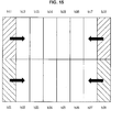
- FIG. 16 is a diagram showing shapes of blocks.
- the screen is divided into a left half and a right half, and each of the halves are divided into 8 blocks b11 to b81 and b12 to b82.
- each of the blocks has a horizontally long shape.
- the movement direction of the blocks at the time of update is a direction perpendicular to the longitudinal direction, namely, the vertical direction.
- the imaging portion can only perform movement in the vertical direction, and the act of sabotage is limited to the vertical direction, it is sufficient if the movement in the vertical direction can be detected.
- the blocks can have a shape in which the horizontal sides are longer than the vertical sides with respect to the direction of change.
- the normalization processing it is determined whether or not to perform normalization, and normalization of the histogram is performed as necessary. Specifically, when there is a bias in the direction of change of the whole screen toward either an increase or a decrease by equal to or greater than the given constant, the histogram is normalized. In this way, mistaken detection of an act of sabotage, which is caused by the AE function or a change in lighting etc., can be reduced. In addition, it is possible to reduce missed detection of an act of sabotage that arises when all the histograms are normalized uniformly. Furthermore, when normalizing the histogram, the change rate that excludes the regions having a different direction of change to the direction of the change of the whole screen is calculated as the normalization value, and thus, highly accurate normalization can be performed.
- the global change detection portion 41 can accurately detect sabotage relating to a global change, such as changing the orientation of the surveillance camera or covering the surveillance camera with a cloth and the like.
- processing by the defocus detection portion 42 will be explained.
- the acquisition portion 21 acquires a camera image. Specifically, the imaging portion captures an image of the predetermined surveillance target and acquires image data of the captured image.
- the image dividing portion 102 divides the image into the number of blocks N.
- the image of each frame based on the image data is divided into 8 ⁇ 8 blocks.
- the update region selection portion 101 selects the update region (the update target blocks). Specifically, of the 8 ⁇ 8 number of blocks, the predetermined number of blocks M (M ⁇ N) is selected as the update target blocks.
- the selection of the update region can be performed in the same manner as the case explained with reference to FIG. 13 , and an explanation is thus omitted here.
- step S51 to step S53 is performed in a similar manner to the processing from step S1 to step S3 of the flowchart shown in FIG. 12 .
- the update region selection portion 101 and the image dividing portion 102 of the defocus detection portion 42 can perform the same processing as that of the update region selection portion 61 and the image dividing portion 63 of the global change detection portion 41 shown in FIG. 3 .
- the update region selection portion 101 and the image dividing portion 102 of the defocus detection portion 42 can have a shared structure with the update region selection portion 61 and the image dividing portion 63 of the global change detection portion 41.
- the update region selection portion 101 and the image dividing portion 102 of the defocus detection portion 42 shown in FIG. 5 can be removed from the defocus detection portion 42, setting of the update region can be received from the update region selection portion 61 of the global change detection portion 41, and supply of image groups of the image region divided up by the image dividing portion 63 can be received.
- the global change detection portion 41 and the defocus detection portion 42 each perform processing of different regions, or perform processing on regions of different sizes
- the global change detection portion 41 and the defocus detection portion 42 can have the respective configurations shown in FIG. 3 and FIG. 5 .
- the number of regions on which processing is performed for each frame may be different for the global change detection portion 41 and the defocus detection portion 42, respectively.
- the global change detection portion 41 and the defocus detection portion 42 perform processing on a different number of regions, the global change detection portion 41 and the defocus detection portion 42 have the respective configurations as shown in FIG. 3 and FIG. 5 .
- the global change detection portion 41 divides 1 frame into 4 groups and, from each of the groups, sets 1 region (1 block) as a processing target. In this case, a total of 4 regions are processed as the processing target (by the processing explained with reference to FIG. 13 ).
- the defocus detection portion 42 divides 1 frame into 4 groups and, from each of the groups, sets 1 region (1 block) as a processing target.
- the global change detection portion 41 may perform processing on all the blocks as sequential processing targets.
- the high frequency filter 104 filters the update region using a predetermined filter. By performing the filtering processing, edges within the update region are extracted.
- the edge strength counter 106 counts the strength of the edges extracted from the region that is the target of processing. Then, using the counted value, at step S56, the threshold determination portion 107 determines, for each of the update target blocks of the current frame, whether the block is the abnormal region or not. An explanation will be added of processing performed by the high frequency filter 104 and by the abnormality determination portion 105 (the edge strength counter 106 and the threshold determination portion 107).
- the high frequency filter 104 extracts a high frequency component included in the input image within a predetermined region. For example, if a transfer function H of the high frequency filter 104 is expressed as a Z transform, it is expressed by Formula (2) below. Note that, in order to simplify the notation, Formula (2) is expressed as a one-dimensional formula, but as the input image is two-dimensional, in actuality, Formula (2) is expanded to a two-dimensional formula and used.
- H Z 1 2 ⁇ - 1 + 2 ⁇ Z - 1 - Z - 2
- the high frequency filter 104 may be configured such that it extracts the high frequency component using transformation processing such as wavelet transformation or the like.
- the high frequency component of the input image that is extracted by the high frequency filter 104 represents the edge strength of the input image (the image within the region specified as the target of processing). This type of edge strength is input into the edge strength counter 106. In the edge strength counter 106, frequency component values of the high frequency component that has passed through the high frequency filter 104 are calculated within the region.
- the edge strength counter 106 counts a number of pixels for which the calculated frequency component value exceeds a predetermined threshold value (hereinafter referred to as a high frequency threshold value). Further, an accumulated value is calculated by summing the high frequency component values of each of the pixels within the region. More specifically, the edge strength counter 106 calculates the number of pixels with a high edge strength within the region and the accumulated value of the edge strength within the region.
- a predetermined threshold value hereinafter referred to as a high frequency threshold value.
- an average value is calculated by dividing the accumulated value by the number of pixels with a high edge strength, and the resulting average value is used in processing described below.
- the average value of the edge strength the accumulated value / the number of pixels with a high edge strength. Note that, when the number of pixels with a high edge strength is zero, namely, when there are no pixels for which the value of the calculated frequency component exceeds the high frequency threshold value, the average value of the edge strength is considered to be zero.
- the threshold determination portion 107 compares the number of pixels and the accumulated value with predetermined threshold values and thus determines whether or not an abnormality has occurred in the region set as the target of processing.
- the threshold determination portion 107 uses the following determination formulas. Determination formula 1: No. of pixels whose edge strength is higher than threshold value ⁇ threshold value of No. of pixels (defocus consensus rate) Determination formula 2: Average value of edge strength ⁇ threshold value of edge strength value (defocus noise th)
- Determination formula 1 is a formula to determine whether or not there are a great number of pixels with a low edge strength. If the focus of the surveillance camera is blurred, a blurred image is captured, and thus, edge themselves are blurred and it is possible that the region will have a great number of pixels with a low edge strength. Determination formula 1 is a formula used to detect this type of situation.
- Determination formula 2 is a formula to determine whether or not the region has low edge strength as a whole.
- the surveillance camera focus is not blurred, a focused image is captured, and thus, in a region where edges exist, the accumulated value of the edge strength is high, and the number of pixels with a high edge strength tends to decrease. Therefore, in a predetermined region of the focused image, the average value of the edge strength tends to be a high value.
- the threshold determination portion 107 determines that there is an abnormality in the region that is the target of processing. In other words, the threshold determination portion 107 takes a logical sum of determination formula 1 and determination formula 2 and outputs the logical sum as a determination result to the counter portion 110 (refer to FIG. 5 ) which performs later processing.
- the abnormal region storage portion 108 updates the determination result for each of the update target blocks of the current frame, at step S57. Specifically, the abnormal region storage portion 108 stores the determination results (namely, the determination results of the number of blocks) of 1 frame for each block, and updates the old determination results with the determination results determined at step S56.
- the counter portion 110 counts the number of abnormal regions of all the regions. More specifically, based on the determination result (the presence or absence of abnormality) from the abnormality determination portion 105 for the update target blocks of the current frame, and on the determination result from the abnormal region storage portion 108 for the blocks other than the update target blocks of the current frame, the number of blocks are counted that are considered to be abnormal regions from among the total of 64 blocks that form the frame of the image of the surveillance target.
- the threshold determination portion 111 determines whether or not the counted number of abnormal regions is greater than a threshold value. More specifically, at step S59, the number of blocks that are counted as the abnormal regions is compared to the predetermined threshold value Thc that is set in advance.
- the threshold value Thc can be a number of abnormal regions of a frame a predetermined number of frames previously.
- step S59 When it is determined at step S59 that the counted number of abnormal regions is larger than the threshold value, the processing advances to step S60 and the threshold determination portion 111 outputs a signal, such as an alarm or the like, that indicates that an act of sabotage has been committed.
- the alarm output at step S60 is a signal notifying to latter processing portions that it is possible that an act of sabotage has been committed.
- the defocus detection portion 42 can accurately detect defocus-related sabotage, such as blurring the focus of the surveillance camera or blurring the zoom.
- FIG. 2 in the present embodiment, among acts of sabotage committed against the surveillance camera, an act of sabotage relating to a global change is detected by the global change detection portion 41 and a defocus-related act of sabotage is detected by the defocus detection portion 42. Further, the detection result integration portion 43 is provided, which integrates results detected by each of the detection portions and outputs a final result as to the presence or absence of the sabotage.
- the detection result integration portion 43 stores, for example, a table such as that shown in FIG. 18 , integrates the results from the two detection portions based on the table and outputs a final result.
- a table such as that shown in FIG. 18
- the detection result from the global change detection portion 41 is a result indicating no abnormality
- the detection result from the defocus detection portion 42 is also a result indicating no abnormality
- the final determination is that of no abnormality.
- a histogram abnormality is a result indicating an abnormality in which luminance changes in a same direction
- the detection result from the defocus detection portion 42 is a result indicating no abnormality
- the histogram abnormality is a result indicating an abnormality in which the luminance changes in the same direction
- the detection result from the defocus detection portion 42 is a result indicating an abnormality
- the histogram abnormality is a result indicating an abnormality in which the luminance changes in a plurality of directions
- the detection result from the defocus detection portion 42 is a result indicating no abnormality
- the histogram abnormality is a result indicating an abnormality in which the luminance changes in the plurality of directions
- the detection result from the defocus detection portion 42 is a result indicating an abnormality
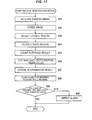
- step S71 it is determined whether or not the determination result from the global change detection portion 41 indicates detection of sabotage.
- step S71 it is determined whether or not the determination result from the global change detection portion 41 indicates detection of sabotage.
- step S72 it is determined whether or not the determination result from the defocus detection portion 42 indicates detection of sabotage.
- step S73 it is determined whether or not the determination result from the defocus detection portion 42 indicates detection of sabotage.
- step S74 the processing advances to step S74.
- the global change has not been detected but the defocusing has been detected, and thus sabotage against the surveillance camera is detected and the sabotage is determined to be that of focus blurring.
- step S74 it is determined that the focus blurring sabotage has occurred.
- This determination result is notified to an administrator who manages the surveillance camera.
- the notification it is possible to notify not simply that the sabotage has occurred, but also to notify that the sabotage is the focus blurring.
- the administrator can rapidly perform appropriate processing in response to the type of sabotage. For example, when notification is made that focus blurring has occurred, it is possible to more rapidly ascertain that it is appropriate to take action to recover the focus than in a case in which it is simply notified that the sabotage has occurred, and the action in response to the sabotage can be taken more quickly.
- the surveillance camera has a function to perform focusing without any command from the administrator, the surveillance camera can start control to perform focusing at the point in time at which the focus blurring sabotage is detected. This type of control can be performed only when the type of sabotage can be determined.
- step S71 when a global change is detected at step S71, the processing advances to step S75.
- step S75 it is determined whether or not the luminance is changing in the same direction.
- step S76 it is determined whether or not defocusing has been detected.
- step S76 When it is determined at step S76 that the defocusing has been detected, the processing advances to step S77. In this case, the global change has been detected in which the luminance changes in the same direction, and the defocusing is also detected. In this type of situation, it is determined that the so-called covering sabotage has occurred in which the surveillance camera is covered with a cloth or the like.
- the global change detection portion 41 detects the abnormality in which the luminance changes in the same direction. Further, when the surveillance camera is covered by the cloth or the like, edges disappear (decrease) from the image captured by the surveillance camera, and there is a high probability that the edge strength will decrease.
- the global change detection portion 41 and the defocus detection portion 42 each output the determination result indicating that there is an abnormality. Further, if the global change detection portion 41 detects the abnormality in which the luminance changes in the same direction, it is possible to determine that the covering sabotage has occurred. In this case also, it is possible to notify not simply that the sabotage has occurred but also to notify that the sabotage is the covering sabotage. It is thus possible to reduce an amount of time until the administrator takes action.
- a method to take action may be notified when performing the notification. For example, when this type of covering sabotage is detected, a message such as, "Covering sabotage has occurred, please remove the covering cloth etc. urgently" may be used as the notification when the sabotage occurs.
- an action may be taken in which video is switched to another surveillance camera that is caused to film the vicinity of the surveillance camera that has detected the occurrence of the sabotage.
- step S76 when it is determined at step S76 that the defocusing has not been detected, the processing advances to step S78. In this case, the global change in which the luminance changes in the same direction has been detected, but the defocusing has not been detected. In this type of situation, it is determined that the turning sabotage has occurred in which the direction of the surveillance camera is changed to another direction.
- the global change detection portion 41 detects that sabotage has occurred.
- the image captured by the surveillance camera that has been turned is also in a focused state, the change in edge strength is small, and sometimes the sabotage is not detected by the defocus detection portion 42.
- the sabotage can be detected by the global change detection portion 41 and it can also be determined that the sabotage is the turning of the surveillance camera.
- the administrator can go to the location in which the surveillance camera is installed and return the surveillance camera to its correct position. If the surveillance camera has a function that can control panning and tilting by remote operation, the administrator can return the surveillance camera to its correct position by remote operation.
- step S75 when it is determined at step S75 that the luminance is not changing in the same direction, namely, when it is determined that the luminance is changing in the plurality of directions, the processing advances to step S79.
- step S79 it is determined whether or not defocusing has been detected.
- step S80 when it is determined that defocusing has been detected, the processing advances to step S80.
- the global change has been detected in which the luminance changes in the plurality of directions, and the defocusing has also been detected.
- zoom blurring it is determined that the zoom of the surveillance camera has been put out of focus. If the zoom of the surveillance camera is out of focus, the image being captured changes and there is a high possibility that the luminance values will change. However, in contrast to a case in which the surveillance camera is covered with a cloth or the like, the possibility that the luminance values change uniformly is low.
- the global change detection portion 41 detects the abnormality in which the luminance changes in the plurality of directions.
- the administrator can go to the location in which the surveillance camera is installed and restore the zoom to its correct position. If the surveillance camera has a function that can control the zoom by remote operation, the administrator can restore the zoom to its correct position by remote operation.
- step S79 when it is determined at step S79 that the defocusing has not been detected, the processing advances to step S78.
- the global change has been detected in which the luminance changes in the plurality of directions, but defocusing has not been detected.
- the global change detection portion 41 and the defocus detection portion 42 each detect the sabotage and it is thus possible to reduce detection oversights and mistaken detection.
- the surveillance camera itself can determine whether or not it can resolve the sabotage.
- the camera can resolve the sabotage, it can start to resolve the sabotage without waiting for instructions from the administrator.
- the global change detection portion 41 and the defocus detection portion 42 each divide the single image into the plurality of regions and determine, for each region, whether or not there is a possibility that sabotage has occurred. Then, using the determination result for each of the regions, a determination is made as to whether the sabotage has occurred with respect to the single image.
- a determination is made as to whether the sabotage has occurred with respect to the single image.
- the series of processes described above can be executed by hardware but can also be executed by software.
- a program that constructs such software is installed into a computer.
- the expression "computer” includes a computer in which dedicated hardware is incorporated and a general-purpose personal computer or the like that is capable of executing various functions when various programs are installed.
- FIG. 20 is a block diagram showing a hardware configuration example of a computer that performs the above-described series of processing using a program.
- a central processing unit (CPU) 1001, a read only memory (ROM) 1002 and a random access memory (RAM) 1003 are mutually connected by a bus 1004.
- An input/output interface 1005 is also connected to the bus 1004.
- An input unit 1006, an output unit 1007, a storage unit 1008, a communication unit 1009 and a drive 1010 are connected to the input/output interface 1005.
- the input unit 1006 is configured from a keyboard, a mouse, a microphone or the like.
- the output unit 1007 configured from a display, a speaker or the like.
- the storage unit 1008 is configured from a hard disk, a non-volatile memory or the like.
- the communication unit 1009 is configured from a network interface or the like.
- the drive 1010 drives a removable media 1011 such as a magnetic disk, an optical disk, a magneto-optical disk, a semiconductor memory or the like.
- the CPU 1001 loads a program that is stored, for example, in the storage unit 1008 onto the RAM 1003 via the input/output interface 1005 and the bus 1004, and executes the program.
- a program that is stored, for example, in the storage unit 1008 onto the RAM 1003 via the input/output interface 1005 and the bus 1004, and executes the program.
- the above-described series of processing is performed.
- Programs to be executed by the computer are provided being recorded in the removable media 1011 which is a packaged media or the like. Also, programs may be provided via a wired or wireless transmission medium, such as a local area network, the Internet or digital satellite broadcasting.
- the program can be installed in the storage unit 1008 via the input/output interface 1005. Further, the program can be received by the communication unit 1009 via a wired or wireless transmission media and installed in the storage unit 1008. Moreover, the program can be installed in advance in the ROM 1002 or the storage unit 1008.
- program executed by a computer may be a program that is processed in time series according to the sequence described in this specification or a program that is processed in parallel or at necessary timing such as upon calling.
- system refers to a whole device composed of a plurality of devices.
- present technology may also be configured as below.
Applications Claiming Priority (1)
| Application Number | Priority Date | Filing Date | Title |
|---|---|---|---|
| JP2011177569A JP2013041400A (ja) | 2011-08-15 | 2011-08-15 | 画像処理装置、画像処理方法、およびプログラム |
Publications (2)
| Publication Number | Publication Date |
|---|---|
| EP2560149A2 true EP2560149A2 (de) | 2013-02-20 |
| EP2560149A3 EP2560149A3 (de) | 2013-11-20 |
Family
ID=47143503
Family Applications (1)
| Application Number | Title | Priority Date | Filing Date |
|---|---|---|---|
| EP12179626.2A Withdrawn EP2560149A3 (de) | 2011-08-15 | 2012-08-08 | Bildverarbeitungsvorrichtung, Bildverarbeitungsverfahren und Programm |
Country Status (4)
| Country | Link |
|---|---|
| US (1) | US8625922B2 (de) |
| EP (1) | EP2560149A3 (de) |
| JP (1) | JP2013041400A (de) |
| CN (1) | CN102957898A (de) |
Cited By (1)
| Publication number | Priority date | Publication date | Assignee | Title |
|---|---|---|---|---|
| CN106600876A (zh) * | 2017-01-24 | 2017-04-26 | 璧典寒 | 自动化机房值班报警系统及报警方法 |
Families Citing this family (8)
| Publication number | Priority date | Publication date | Assignee | Title |
|---|---|---|---|---|
| JP2013041400A (ja) * | 2011-08-15 | 2013-02-28 | Sony Corp | 画像処理装置、画像処理方法、およびプログラム |
| JP2017027091A (ja) * | 2013-12-03 | 2017-02-02 | 三菱電機株式会社 | 撮影障害検出装置及び撮影障害検出プログラム |
| EP3151552A4 (de) | 2014-05-30 | 2018-02-21 | Hitachi Kokusai Electric Inc. | Überwachungssystem und kameravorrichtung |
| CN104918014A (zh) * | 2015-06-04 | 2015-09-16 | 广州长视电子有限公司 | 一种遇障后自动填补监控区域的监控系统 |
| TWI569212B (zh) * | 2015-12-10 | 2017-02-01 | 財團法人工業技術研究院 | 影像辨識方法 |
| TWI616086B (zh) * | 2016-10-20 | 2018-02-21 | 攝影裝置畫面異常種類之檢測方法 | |
| JP6783732B2 (ja) * | 2017-09-15 | 2020-11-11 | 株式会社東芝 | 画像処理装置および画像処理方法 |
| CN108734175A (zh) * | 2018-04-28 | 2018-11-02 | 北京猎户星空科技有限公司 | 一种图像特征的提取方法、装置及电子设备 |
Citations (3)
| Publication number | Priority date | Publication date | Assignee | Title |
|---|---|---|---|---|
| JP4227539B2 (ja) | 2004-03-02 | 2009-02-18 | 綜合警備保障株式会社 | 監視カメラ妨害検知装置 |
| JP4626632B2 (ja) | 2007-06-25 | 2011-02-09 | 株式会社日立製作所 | 映像監視システム |
| JP2011177569A (ja) | 2009-09-07 | 2011-09-15 | Panasonic Electric Works Co Ltd | 視機能検査装置 |
Family Cites Families (18)
| Publication number | Priority date | Publication date | Assignee | Title |
|---|---|---|---|---|
| CA2035952A1 (en) | 1990-04-17 | 1991-10-18 | Prudence T. Z. Kapauan | Order independent rule-based program specification system |
| JPH0799862B2 (ja) * | 1991-03-22 | 1995-10-25 | 松下電器産業株式会社 | 階調補正装置 |
| JPH05316446A (ja) * | 1992-05-08 | 1993-11-26 | Matsushita Electric Ind Co Ltd | 階調補正装置 |
| US7079157B2 (en) * | 2000-03-17 | 2006-07-18 | Sun Microsystems, Inc. | Matching the edges of multiple overlapping screen images |
| EP1164784A1 (de) * | 2000-06-13 | 2001-12-19 | Koninklijke Philips Electronics N.V. | Verhinderung des Wölbungsphänomens |
| WO2003009216A1 (en) * | 2001-07-17 | 2003-01-30 | Yesvideo, Inc. | Automatic selection of a visual image based on quality |
| US6677956B2 (en) * | 2001-08-15 | 2004-01-13 | Mitsubishi Electric Research Laboratories, Inc. | Method for cross-fading intensities of multiple images of a scene for seamless reconstruction |
| US7068274B2 (en) * | 2001-08-15 | 2006-06-27 | Mitsubishi Electric Research Laboratories, Inc. | System and method for animating real objects with projected images |
| KR100444784B1 (ko) * | 2001-11-15 | 2004-08-21 | 주식회사 에이로직스 | 에지검출을 통한 경보발생방법 및 보안 시스템 |
| DE10201520A1 (de) * | 2002-01-17 | 2003-07-31 | Bosch Gmbh Robert | Verfahren und Vorrichtung zur Bildfehlererkennung b zw. -anzeige bei Bildaufnahmesystemen |
| JP2004032551A (ja) * | 2002-06-27 | 2004-01-29 | Seiko Epson Corp | 画像処理方法、画像処理装置及びプロジェクタ |
| WO2007142227A1 (ja) * | 2006-06-07 | 2007-12-13 | Nec Corporation | 画像方向判定装置、画像方向判定方法、および画像方向判定用プログラム |
| US8494211B2 (en) * | 2007-10-19 | 2013-07-23 | Pasco Corporation | House change judgment method and house change judgment program |
| JP4670943B2 (ja) * | 2008-11-27 | 2011-04-13 | ソニー株式会社 | 監視装置、及び妨害検知方法 |
| CN101489130B (zh) * | 2009-01-21 | 2010-09-15 | 西安交通大学 | 基于图像边缘差异统计特性的全参考型图像质量评价方法 |
| JP5561524B2 (ja) * | 2010-03-19 | 2014-07-30 | ソニー株式会社 | 画像処理装置および方法、並びにプログラム |
| JP5637383B2 (ja) * | 2010-12-15 | 2014-12-10 | ソニー株式会社 | 画像処理装置、画像処理方法、およびプログラム |
| JP2013041400A (ja) * | 2011-08-15 | 2013-02-28 | Sony Corp | 画像処理装置、画像処理方法、およびプログラム |
-
2011
- 2011-08-15 JP JP2011177569A patent/JP2013041400A/ja not_active Abandoned
-
2012
- 2012-08-02 US US13/565,201 patent/US8625922B2/en not_active Expired - Fee Related
- 2012-08-08 EP EP12179626.2A patent/EP2560149A3/de not_active Withdrawn
- 2012-08-15 CN CN2012102907334A patent/CN102957898A/zh active Pending
Patent Citations (3)
| Publication number | Priority date | Publication date | Assignee | Title |
|---|---|---|---|---|
| JP4227539B2 (ja) | 2004-03-02 | 2009-02-18 | 綜合警備保障株式会社 | 監視カメラ妨害検知装置 |
| JP4626632B2 (ja) | 2007-06-25 | 2011-02-09 | 株式会社日立製作所 | 映像監視システム |
| JP2011177569A (ja) | 2009-09-07 | 2011-09-15 | Panasonic Electric Works Co Ltd | 視機能検査装置 |
Cited By (1)
| Publication number | Priority date | Publication date | Assignee | Title |
|---|---|---|---|---|
| CN106600876A (zh) * | 2017-01-24 | 2017-04-26 | 璧典寒 | 自动化机房值班报警系统及报警方法 |
Also Published As
| Publication number | Publication date |
|---|---|
| JP2013041400A (ja) | 2013-02-28 |
| CN102957898A (zh) | 2013-03-06 |
| US8625922B2 (en) | 2014-01-07 |
| EP2560149A3 (de) | 2013-11-20 |
| US20130044964A1 (en) | 2013-02-21 |
Similar Documents
| Publication | Publication Date | Title |
|---|---|---|
| EP2560149A2 (de) | Bildverarbeitungsvorrichtung, Bildverarbeitungsverfahren und Programm | |
| CN110121882B (zh) | 一种图像处理方法及装置 | |
| US8494267B2 (en) | Image processing device, image processing method, and program for normalizing a histogram | |
| US9330446B2 (en) | Method and apparatus for processing image | |
| CN105262954B (zh) | 触发摄像头自动聚焦的方法和装置 | |
| US8508599B2 (en) | Motion vector detection apparatus, motion vector detection method, and image capturing apparatus | |
| JP5484184B2 (ja) | 画像処理装置、画像処理方法及びプログラム | |
| US11107246B2 (en) | Method and device for capturing target object and video monitoring device | |
| CN111163259A (zh) | 一种图像抓拍方法、监控相机及监控系统 | |
| CN110796600B (zh) | 一种图像超分重建方法、图像超分重建装置及电子设备 | |
| JP2014178739A (ja) | 画像処理装置及び画像処理方法、並びにプログラム | |
| CN110866486B (zh) | 主体检测方法和装置、电子设备、计算机可读存储介质 | |
| CN108335272B (zh) | 一种拍摄图片的方法及设备 | |
| CN110796041B (zh) | 主体识别方法和装置、电子设备、计算机可读存储介质 | |
| CN111080571A (zh) | 摄像头遮挡状态检测方法、装置、终端和存储介质 | |
| CN111444555B (zh) | 一种测温信息显示方法、装置及终端设备 | |
| US10455144B2 (en) | Information processing apparatus, information processing method, system, and non-transitory computer-readable storage medium | |
| CN113452901A (zh) | 图像采集方法及装置、电子设备、计算机可读存储介质 | |
| WO2020098325A1 (zh) | 一种图像合成方法、电子设备及存储介质 | |
| JP2015138399A (ja) | 画像処理装置、画像処理方法、及びコンピュータプログラム | |
| CN111126147B (zh) | 图像处理方法、装置和电子系统 | |
| JP4628851B2 (ja) | 物体検出方法および物体検出装置 | |
| CN110650288B (zh) | 对焦控制方法和装置、电子设备、计算机可读存储介质 | |
| TWI693577B (zh) | 影像產生方法與電子裝置 | |
| CN113822927B (zh) | 一种适用弱质量图像的人脸检测方法、装置、介质及设备 |
Legal Events
| Date | Code | Title | Description |
|---|---|---|---|
| PUAI | Public reference made under article 153(3) epc to a published international application that has entered the european phase |
Free format text: ORIGINAL CODE: 0009012 |
|
| 17P | Request for examination filed |
Effective date: 20120808 |
|
| AK | Designated contracting states |
Kind code of ref document: A2 Designated state(s): AL AT BE BG CH CY CZ DE DK EE ES FI FR GB GR HR HU IE IS IT LI LT LU LV MC MK MT NL NO PL PT RO RS SE SI SK SM TR |
|
| AX | Request for extension of the european patent |
Extension state: BA ME |
|
| PUAL | Search report despatched |
Free format text: ORIGINAL CODE: 0009013 |
|
| AK | Designated contracting states |
Kind code of ref document: A3 Designated state(s): AL AT BE BG CH CY CZ DE DK EE ES FI FR GB GR HR HU IE IS IT LI LT LU LV MC MK MT NL NO PL PT RO RS SE SI SK SM TR |
|
| AX | Request for extension of the european patent |
Extension state: BA ME |
|
| RIC1 | Information provided on ipc code assigned before grant |
Ipc: G08B 29/04 20060101AFI20131014BHEP Ipc: G08B 13/196 20060101ALN20131014BHEP |
|
| STAA | Information on the status of an ep patent application or granted ep patent |
Free format text: STATUS: THE APPLICATION HAS BEEN WITHDRAWN |
|
| 18W | Application withdrawn |
Effective date: 20150129 |