EP2559832B1 - Outside handle device for vehicle door - Google Patents
Outside handle device for vehicle door Download PDFInfo
- Publication number
- EP2559832B1 EP2559832B1 EP11768905.9A EP11768905A EP2559832B1 EP 2559832 B1 EP2559832 B1 EP 2559832B1 EP 11768905 A EP11768905 A EP 11768905A EP 2559832 B1 EP2559832 B1 EP 2559832B1
- Authority
- EP
- European Patent Office
- Prior art keywords
- bolt
- base plate
- latching
- outer panel
- end part
- Prior art date
- Legal status (The legal status is an assumption and is not a legal conclusion. Google has not performed a legal analysis and makes no representation as to the accuracy of the status listed.)
- Active
Links
Images


Classifications
-
- E—FIXED CONSTRUCTIONS
- E05—LOCKS; KEYS; WINDOW OR DOOR FITTINGS; SAFES
- E05B—LOCKS; ACCESSORIES THEREFOR; HANDCUFFS
- E05B79/00—Mounting or connecting vehicle locks or parts thereof
- E05B79/02—Mounting of vehicle locks or parts thereof
- E05B79/06—Mounting of handles, e.g. to the wing or to the lock
-
- E—FIXED CONSTRUCTIONS
- E05—LOCKS; KEYS; WINDOW OR DOOR FITTINGS; SAFES
- E05B—LOCKS; ACCESSORIES THEREFOR; HANDCUFFS
- E05B17/00—Accessories in connection with locks
- E05B17/0012—Accessories in connection with locks for lock parts held in place before or during mounting on the wing
-
- E—FIXED CONSTRUCTIONS
- E05—LOCKS; KEYS; WINDOW OR DOOR FITTINGS; SAFES
- E05B—LOCKS; ACCESSORIES THEREFOR; HANDCUFFS
- E05B81/00—Power-actuated vehicle locks
- E05B81/54—Electrical circuits
- E05B81/64—Monitoring or sensing, e.g. by using switches or sensors
- E05B81/76—Detection of handle operation; Detection of a user approaching a handle; Electrical switching actions performed by door handles
-
- E—FIXED CONSTRUCTIONS
- E05—LOCKS; KEYS; WINDOW OR DOOR FITTINGS; SAFES
- E05B—LOCKS; ACCESSORIES THEREFOR; HANDCUFFS
- E05B85/00—Details of vehicle locks not provided for in groups E05B77/00 - E05B83/00
- E05B85/10—Handles
-
- E—FIXED CONSTRUCTIONS
- E05—LOCKS; KEYS; WINDOW OR DOOR FITTINGS; SAFES
- E05B—LOCKS; ACCESSORIES THEREFOR; HANDCUFFS
- E05B85/00—Details of vehicle locks not provided for in groups E05B77/00 - E05B83/00
- E05B85/10—Handles
- E05B85/14—Handles pivoted about an axis parallel to the wing
- E05B85/16—Handles pivoted about an axis parallel to the wing a longitudinal grip part being pivoted at one end about an axis perpendicular to the longitudinal axis of the grip part
-
- Y—GENERAL TAGGING OF NEW TECHNOLOGICAL DEVELOPMENTS; GENERAL TAGGING OF CROSS-SECTIONAL TECHNOLOGIES SPANNING OVER SEVERAL SECTIONS OF THE IPC; TECHNICAL SUBJECTS COVERED BY FORMER USPC CROSS-REFERENCE ART COLLECTIONS [XRACs] AND DIGESTS
- Y10—TECHNICAL SUBJECTS COVERED BY FORMER USPC
- Y10S—TECHNICAL SUBJECTS COVERED BY FORMER USPC CROSS-REFERENCE ART COLLECTIONS [XRACs] AND DIGESTS
- Y10S292/00—Closure fasteners
- Y10S292/53—Mounting and attachment
-
- Y—GENERAL TAGGING OF NEW TECHNOLOGICAL DEVELOPMENTS; GENERAL TAGGING OF CROSS-SECTIONAL TECHNOLOGIES SPANNING OVER SEVERAL SECTIONS OF THE IPC; TECHNICAL SUBJECTS COVERED BY FORMER USPC CROSS-REFERENCE ART COLLECTIONS [XRACs] AND DIGESTS
- Y10—TECHNICAL SUBJECTS COVERED BY FORMER USPC
- Y10T—TECHNICAL SUBJECTS COVERED BY FORMER US CLASSIFICATION
- Y10T292/00—Closure fasteners
- Y10T292/57—Operators with knobs or handles
Definitions
- the present invention relates to an outside handle device for a vehicle door, the outside handle device including a handle main body having a grip portion disposed outside an outer panel of the vehicle door, and a base plate fixed to an inner face of the outer panel, the handle main body engaging with the base plate.
- Patent Document 1 Japanese Patent Application Laid-open No. 2003-27773
- the present invention has been accomplished in light of such circumstances, and it is an object thereof to provide an outside handle device for a vehicle door that makes assembly of a handle main body onto a door easy and can reduce the number of components and the number of assembly steps.
- an outside handle device for a vehicle door comprising a handle main body having a grip portion disposed outside an outer panel of a vehicle door, and a base plate fixed to an inner face of the outer panel, the handle main body engaging the base plate, characterized in that the outer panel is provided with a latching hole and an insertion hole, the latching hole having inserted therethrough and engaged therewith a first bolt or a second bolt, the first bolt having an enlarged diameter head portion and being screwed into one end part in a longitudinal direction of the grip portion, the second bolt having a base thereof implanted in one end part in the longitudinal direction of the grip portion and having a nut screwed around a tip side thereof, and the insertion hole having inserted therethrough a penetrating portion that is provided on the other end part in the longitudinal direction of the grip portion, penetrates into the outer panel, and has a latching groove provided on the outer periphery thereof, the
- the latching hole comprises an insertion hole portion and a latching slit portion, the insertion hole portion enabling the enlarged diameter head portion or the nut to be inserted therethrough, the latching slit portion being connected to the insertion hole portion while enabling a shaft portion of the first bolt or the second bolt to be inserted therethrough but making it impossible for the enlarged diameter head portion or the nut to be inserted therethrough, and in a state in which the latching hole has the first bolt or the second bolt inserted therethrough and engaged therewith and the other end part of the base plate is engaged with the latching groove of the penetrating portion, the direction of opening of the first engagement recess is set so as to be a direction different from the direction of opening of the latching slit portion toward the insertion hole portion.
- the penetrating portion is provided with a through hole that enables a harness connected to an electrical component disposed within the grip portion to be led out.
- the base plate is formed into a shape that exhibits resilience between the latching groove of the penetrating portion and the outer panel.
- a board 22 of an embodiment corresponds to the electrical component of the present invention.
- the handle main body can be provisionally assembled onto the outer panel by inserting the penetrating portion through the insertion hole while engaging the first bolt or the second bolt on one end side of the grip portion of the handle main body with the latching hole, and in this provisionally assembled state the base plate in a state in which the first bolt or the second bolt is housed in the first engagement recess in one end part of the base plate is pivoted around the axis of the first bolt or the second bolt, thus enabling the other end part of the base plate to be engaged with the latching groove on the outer periphery of the penetrating portion; furthermore, tightening the first bolt or the nut so as to make the enlarged diameter head portion of the first bolt or the nut screwed around the second bolt abut against and be engaged with said one end part of the base plate allows the handle main body to be fixed to the outer panel.
- the latching hole is formed from the insertion hole portion, which enables the enlarged diameter head portion or the nut to be inserted therethrough, and the latching slit portion connected to the insertion hole portion, which enables the shaft portion of the first bolt or the second bolt to be inserted therethrough but makes it impossible for the enlarged diameter head portion or the nut to be inserted therethrough, and the direction of opening of the first engagement recess, which is provided in the base plate so as to open on the outer edge thereof, is different from the direction of opening of the latching slit portion toward the insertion hole portion, when one end part of the base plate is engaged with the first bolt or the second bolt in a state in which the shaft portion of the first bolt or the second bolt is inserted through the latching slit portion of the latching hole and the first bolt or the second bolt is inserted through and engaged with the latching hole, the shaft portion of the first bolt or the second bolt does not move from the latching slit portion toward the insertion
- the harness connected to the electrical component disposed within the grip portion is led out via the interior of the through hole provided in the penetrating portion, it is possible to prevent the harness from being caught between the handle main body and the outer panel.
- the base plate since the base plate exhibits resilience between the latching groove and the outer panel in a state in which it is engaged with the latching groove of the penetrating portion, it is possible to prevent rattling of the base plate from occurring in a state in which the handle main body is secured thereto.
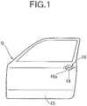
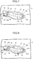
- FIG. 1 A first mode for carrying out the present invention is explained by reference to FIG. 1 to FIG. 9 ; first, in FIG. 1 , a vehicle door D is switched between locked and unlocked states by electric power, a handle main body 16 having a grip portion 16a extending lengthwise in the vehicle fore-and-aft direction and positioned outside an outer panel 15 of the vehicle door D is disposed on the outer panel 15, and this handle main body 16 is fixed to the outer panel 15 by being engaged with a base plate 17A (see FIG. 2 ) fixed onto an inner face of the outer panel 15. Moreover, the outer panel 15 is provided with an insertion recess 18, into which part of a hand gripping the grip portion 16a can be inserted.
- the handle main body 16 has a synthetic resin handle base body 19 extending over the entire length of the grip portion 16a, and a synthetic resin cover member 20 joined to a reverse face of a rear half of the handle base body 19 by means of a plurality of screw members 21, the grip portion 16a being formed from the handle base body 19 and part of the cover member 20. Furthermore, housed between the handle base body 19 and the cover member 20 are a board 22 fixed to an inner face of the cover member 20, a sensor 23 disposed on the board 22 in order to detect a state in which the grip portion 16a is gripped by a vehicle user, and an antenna 24 disposed on the board 22 so that the sensor 23 is interposed between the antenna 24 and the board 22.
- a cylindrical nut 25 having at one end a flange portion 25a protruding radially outward, and screwed into this nut 25 is a shaft portion 26b of a first bolt 26 having an enlarged diameter head portion 26a.
- a first seal member 27A is fitted onto the face of said one end part of the grip portion 16a that faces the outer panel 15 side, the first seal member 27A being formed into a flat plate shape integrally having a cover portion 27a covering the flange portion 25a of the nut 25 from opposite faces, said one end part of the grip portion 16a is abutted against an outer face of the outer panel 15 via the first seal member 27A, and the first bolt 26 is screwed into said one end part of the grip portion 16a so as to extend through a middle section of the first seal member 27A and project outward.
- the other end part (rear end part in this embodiment) in the longitudinal direction of the grip portion 16a is provided with a penetrating portion 20a penetrating into the outer panel 15, in this embodiment the penetrating portion 20a being provided integrally with the cover member 20 forming part of the grip portion 16a.
- the penetrating portion 20a is formed into an angular tube shape having a rectangular cross-sectional shape, and the penetrating portion 20a is provided with a through hole 29, a harness 28 connected to the board 22, which is an electrical component disposed within the grip portion 16a, being led out via the through hole 29.
- a flat plate-shaped second seal member 31 is fitted onto a face of said other end part of the grip portion 16a that faces the outer panel 15 side, the second seal member 31 having an opening 30 for the penetrating portion 20a to be inserted through, and said other end part of the grip portion 16a is abutted against the outer face of the outer panel 15 via the second seal member 31.
- the penetrating portion 20a projects from the second seal member 31, and a pair of vertically extending latching grooves 32 and 32 are provided on the outer periphery of a section of the penetrating portion 20a that projects from the second seal member 31.
- the base plate 17A is formed so as to extend lengthwise in the passenger vehicle fore-and-aft direction so as to correspond the grip portion 16a of the handle main body 16 while integrally having a first engagement portion 35 that abuts against an inner face of the outer panel 15 on one end (front end in this embodiment) side of the handle main body 16 and enables the enlarged diameter head portion 26a of the first bolt 26 to be engaged therewith, a second engagement portion 36 that abuts against the inner face of the outer panel 15 on the other end (rear end in this embodiment) side of the handle main body 16 and can engage with the outer periphery of the penetrating portion 20a, a curved portion 37 that provides a connection between the first and second engagement portions 35 and 36 and protrudes to the side opposite to the outer panel 15, and an abutment plate part 38 that is connected to the second engagement portion 36 on the side opposite to the curved portion 37 and abuts against the inner face of the outer panel 15.
- the first engagement portion 35 in one end part of the base plate 17A is formed into a flat plate shape, and a first engagement recess 43A is provided in the first engagement portion 35, the first engagement recess 43A housing the first bolt 26 while enabling the enlarged diameter head portion 26a to be engaged with the first engagement portion 35.
- the second engagement portion 36 in the other end part of the base plate 17A is formed into a trapezoidal shape while projecting toward a side away from the outer panel 15, and a second engagement recess 44 is provided in the second engagement portion 36, the second engagement recess 44 housing the penetrating portion 20a while enabling the second engagement portion 36 to be engaged with the latching grooves 32 of the penetrating portion 20a by pivoting the base plate 17A around the axis of the first bolt 26 in a state in which the first bolt 26 is housed in the first engagement recess 43A.
- the abutment plate part 38 is formed into a flat plate shape, and a connector retaining part 39 is provided so as to be connected at right angles to the side edge of a lower part of the abutment plate part 38.
- a connector retaining part 39 is formed in the connector retaining part 39 so as to be connected at right angles to the side edge of a lower part of the abutment plate part 38.
- a retaining hole 42 for resiliently engaging with and retaining a clip 41 mounted on a connector 40, the harness 28 led out via the through hole 29 of the penetrating portion 20a being connected to the connector 40.
- the first and second engagement recesses 43A and 44 are provided in the base plate 17A so as to open on the side edge of the base plate 17A, and in this embodiment the first engagement recess 43A is provided on the front edge of a front end part of the first engagement portion 35 so as to open toward the front in the passenger vehicle fore-and-aft direction, and the second engagement recess 44 is provided on the lower edge of the second engagement portion 36 so as to open downward.
- the second engagement portion 36 has a trapezoidal shape, in a state in which the second engagement portion 36 is engaged with the latching grooves 32 of the penetrating portion 20a, the second engagement portion 36 exhibits resilience between the latching grooves 32 and the outer panel 15.
- the outer panel 15 is provided with a latching hole 45 and an insertion hole 46, the latching hole 45 allowing the first bolt 26 having the enlarged diameter head portion 26a and screwed into one end part in the longitudinal direction of the grip portion 16a to be inserted therethrough and engaged therewith, and the insertion hole 46 allowing the penetrating portion 20a provided on the other end part in the longitudinal direction of the grip portion 16a to be inserted therethrough.
- the outer panel 15 is also provided with a protruding part 47 protruding inward so as to form the insertion recess 18 provided on the outer face side of the outer panel 15,
- the latching hole 45 is provided in a first flat portion 47a formed on a front part of the protruding part 47 along the vehicle fore-and-aft direction
- the insertion hole 46 is provided in a second flat portion 47b formed in a rear part of the protruding part 47 along the fore-and-aft direction.
- the first engagement portion 35 on one end side of the base plate 17A abuts against the first flat portion 47a
- the second engagement portion 36 and the abutment plate part 38 on the other end side of the base plate 17A abut against the second flat portion 47b.
- the latching hole 45 is formed from an insertion hole portion 45a that enables the enlarged diameter head portion 26a to be inserted therethrough, and a latching slit portion 45b connected to the insertion hole portion 45a while enabling the shaft portion 26b of the first bolt 26 to be inserted therethrough and making it impossible for the enlarged diameter head portion 26a to be inserted therethrough, and is provided in the outer panel 15 so that, in a state in which the penetrating portion 20a is inserted through the insertion hole 46, the handle main body 16 can be provisionally assembled onto the outer panel 15 by engagement of the first bolt 26 with the latching hole 45.
- the penetrating portion 20a is inserted through the insertion hole 46 while engaging the first bolt 26 with the latching hole 45 by inserting the enlarged diameter head portion 26a through the insertion hole portion 45a and them moving the shaft portion 26b toward the latching slit portion 45b side, thereby enabling the handle main body 16 to be provisionally assembled onto the outer panel 15.
- the direction of opening of the first engagement recess 43A is set so as to be a direction different from the direction of opening of the latching slit portion 45b toward the insertion hole portion 45a, and in this embodiment, the direction of opening of the first engagement recess 43A is forward along the passenger vehicle fore-and-aft direction whereas the direction of opening of the latching slit portion 45b toward the insertion hole portion 45a is rearward along the passenger vehicle fore-and-aft direction.
- the latching hole 45 which has inserted therethrough and engaged therewith the first bolt 26 having the enlarged diameter head portion 26a and being screwed into one end part in the longitudinal direction of the grip portion 16a
- the insertion hole 46 which has inserted therethrough the penetrating portion 20a provided on the other end part in the longitudinal direction of the grip portion 16a and penetrating into the outer panel 15, are provided in the outer panel 15 while enabling the handle main body 16 to be provisionally assembled onto the outer panel 15 such that the penetrating portion 20a is inserted through the insertion hole 46 while the first bolt 26 is engaged with the latching hole 45.
- the first engagement recess 43A which houses the first bolt 26 while enabling one end part of the base plate 17A to be engaged with the enlarged diameter head portion 26a
- the second engagement recess 44 which houses the penetrating portion 20a while enabling the other end part of the base plate 17A to be engaged with the latching grooves 32 on the outer periphery of the penetrating portion 20a by pivoting the base plate 17A having the first bolt 26 housed in the first engagement recess 43A around the axis of the first bolt 26, are provided in the base plate 17A so as to open on the side edge of the base plate 17A.
- the latching hole 45 provided in the outer panel 15 is formed from the insertion hole portion 45a, which enables the enlarged diameter head portion 26a to be inserted therethrough, and the latching slit portion 45b, which is connected to the insertion hole portion 45a while enabling the shaft portion 26b of the first bolt 26 to be inserted therethrough but making it impossible for the enlarged diameter head portion 26a to be inserted therethrough; in a state in which the first bolt 26 is inserted through and engaged with the latching hole 45 and the other end part of the base plate 17A is engaged with the latching grooves 32 of the penetrating portion 20a, since the direction of opening of the first engagement recess 43A is set so as to be a different direction from the direction of opening of the latching slit portion 45b toward the insertion hole portion 45a, when said one end part of the base plate 17A is engaged with the first bolt 26 in a state in which the first bolt 26 is inserted through and engaged with the latching hole 45 while inserting the shaft portion 26b of the first
- the penetrating portion 20a provided in the other end part of the handle main body 16 is provided with the through hole 29, via which the harness 28 connected to the board 22 disposed within the grip portion 16a is led out, it is possible to prevent the harness 28 from being caught between the handle main body 16 and the outer panel 15.
- the second engagement portion 36 in the other end part of the base plate 17A is formed into a shape that exhibits resilience between the latching grooves 32 of the penetrating portion 20a and the outer panel 15, it is possible to prevent the base plate 17A having the handle main body 16 secured thereto from rattling.
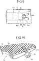
- FIG. 10 A second embodiment of the present invention is explained by reference to FIG. 10 ; portions corresponding to those of the first embodiment are denoted by the same reference numerals and symbols and only illustrated, a detailed explanation thereof being omitted.
- the base of a second bolt 49 is implanted in one end part of a grip portion 16a of a handle main body 16, and a flat plate-shaped first seal member 27B having the second bolt 49 projecting from its middle section is fitted onto said one end part of the grip portion 16a.
- a nut 50 is screwed around the tip side of the second bolt 49, the second bolt 49 can be inserted through and engaged with a latching hole 45 (see first embodiment) provided in an outer panel 15 while having the nut 50 screwed onto the tip side, and a first engagement recess 43A (see first embodiment) provided in a first engagement portion 35 of a base plate 17A can house the second bolt 49 so as to engage the nut 50 with the first engagement portion 35.
- the front edge of the front end part of the first engagement portion 35 enabling the enlarged diameter head portion 26a of the first bolt 26 or the nut 50 screwed around the second bolt 49 to be engaged therewith is provided with the first engagement recess 43A opening forward in the passenger vehicle fore-and-aft direction, but the first engagement recess may open in a direction different from the direction of opening of the latching slit portion 45b toward the insertion hole portion 45a in a state in which the first bolt 26 or the second bolt 49 is inserted through and engaged with the latching hole 45 while enabling the base plate having the first bolt 26 or the second bolt 49 housed in the first engagement recess to be pivoted around the axis of the first bolt 26 or the second bolt 49, and the other end part of the base plate 17 is engaged with the latching grooves 32 of the penetrating portion 20a; as in a first modification example shown in FIG.
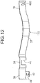
- a first engagement recess 43B opening downward may be provided in a first engagement portion 35 in one end part of a base plate 17B, or alternatively as in a second modification example shown FIG. 12 a first engagement recess 43C inclined forward and downward and opening obliquely forward and downward may be provided in a first engagement portion 35 in one end part of a base plate 17C.
Landscapes
- Lock And Its Accessories (AREA)
Applications Claiming Priority (2)
| Application Number | Priority Date | Filing Date | Title |
|---|---|---|---|
| JP2010094237A JP5162617B2 (ja) | 2010-04-15 | 2010-04-15 | 車両用ドアのアウトハンドル装置 |
| PCT/JP2011/059237 WO2011129384A1 (ja) | 2010-04-15 | 2011-04-14 | 車両用ドアのアウトハンドル装置 |
Publications (3)
| Publication Number | Publication Date |
|---|---|
| EP2559832A1 EP2559832A1 (en) | 2013-02-20 |
| EP2559832A4 EP2559832A4 (en) | 2016-02-24 |
| EP2559832B1 true EP2559832B1 (en) | 2017-03-15 |
Family
ID=44798753
Family Applications (1)
| Application Number | Title | Priority Date | Filing Date |
|---|---|---|---|
| EP11768905.9A Active EP2559832B1 (en) | 2010-04-15 | 2011-04-14 | Outside handle device for vehicle door |
Country Status (5)
| Country | Link |
|---|---|
| US (1) | US8857867B2 (ja) |
| EP (1) | EP2559832B1 (ja) |
| JP (1) | JP5162617B2 (ja) |
| CN (1) | CN102844508B (ja) |
| WO (1) | WO2011129384A1 (ja) |
Families Citing this family (26)
| Publication number | Priority date | Publication date | Assignee | Title |
|---|---|---|---|---|
| CN105960498B (zh) * | 2014-02-28 | 2019-05-10 | 胡夫·许尔斯贝克和福斯特有限及两合公司 | 用于车辆的门把手系统 |
| JP6499827B2 (ja) * | 2014-03-14 | 2019-04-10 | 株式会社アルファ | 車両のドアハンドル |
| JP6388121B2 (ja) | 2014-09-30 | 2018-09-12 | アイシン精機株式会社 | 車両用ドアハンドル装置 |
| CN107660249B (zh) | 2015-03-18 | 2019-08-27 | 伊利诺斯工具制品有限公司 | 车门把手组件 |
| DE102015110531A1 (de) * | 2015-06-30 | 2017-01-05 | Huf Hülsbeck & Fürst Gmbh & Co. Kg | Türgriffsystem für Fahrzeuge |
| US9945151B2 (en) * | 2015-12-10 | 2018-04-17 | Whirlpool Corporation | Invisible handle locking system |
| CN106088864A (zh) * | 2016-08-10 | 2016-11-09 | 上汽通用五菱汽车股份有限公司 | 一种具有镶嵌螺母的汽车尾门拉手 |
| USD817824S1 (en) * | 2016-08-23 | 2018-05-15 | Bayerische Motoren Werke Aktiengesellschaft | Front bumper for a vehicle |
| USD842174S1 (en) * | 2017-03-22 | 2019-03-05 | Ningbo Geely Automobile Research & Development Co., Ltd. | Front grille for a vehicle |
| USD848334S1 (en) * | 2017-04-10 | 2019-05-14 | Nio Nextev Limited | Right vehicle side door |
| USD851003S1 (en) * | 2017-04-10 | 2019-06-11 | Nio Nextev Limited | Left vehicle side door |
| ZAA201701739S (en) * | 2017-05-10 | 2019-03-27 | Bayerische Motoren Werke Ag | Motor vehicles |
| USD840298S1 (en) * | 2017-05-24 | 2019-02-12 | Jaguar Land Rover Limited | Front bumper |
| USD852105S1 (en) * | 2017-06-15 | 2019-06-25 | Jaguar Land Rover Limited | Roof for a vehicle |
| USD889343S1 (en) * | 2017-08-29 | 2020-07-07 | Jaguar Land Rover Limited | Front door for a vehicle |
| USD876995S1 (en) * | 2017-09-06 | 2020-03-03 | Jaguar Land Rover Limited | Vehicle front grille, including a portion thereof |
| USD839164S1 (en) * | 2017-10-17 | 2019-01-29 | GM Global Technology Operations LLC | Vehicle side door |
| DE102018107503A1 (de) * | 2018-03-28 | 2019-10-02 | Huf Hülsbeck & Fürst Gmbh & Co. Kg | Griffvorrichtung für eine Tür oder eine Klappe |
| USD928678S1 (en) * | 2019-01-24 | 2021-08-24 | Dv8, Llc | Pair of front doors |
| USD930544S1 (en) * | 2019-01-31 | 2021-09-14 | Kia Motors Corporation | Front door panel for automobiles |
| USD915973S1 (en) * | 2019-02-25 | 2021-04-13 | Hyundai Motor Company | Front door panel for an automobile |
| USD945941S1 (en) * | 2020-01-30 | 2022-03-15 | Kia Motors Corporation | Front door panel for an automobile |
| USD971807S1 (en) * | 2020-06-01 | 2022-12-06 | Hyundai Motor Company | Front door panel for automobile |
| USD994566S1 (en) * | 2020-06-01 | 2023-08-08 | Hyundai Motor Company | Rear door panel for automobile |
| USD947738S1 (en) * | 2020-07-01 | 2022-04-05 | Hyundai Motor Company | Front door panel for vehicles |
| USD956650S1 (en) * | 2020-08-18 | 2022-07-05 | Hyundai Motor Company | Front door panel for vehicles |
Family Cites Families (10)
| Publication number | Priority date | Publication date | Assignee | Title |
|---|---|---|---|---|
| US5519917A (en) * | 1994-08-05 | 1996-05-28 | Cambridge Industries, Inc. | Mounting device for a front mounted removable handle and the like |
| KR0163083B1 (ko) | 1995-12-28 | 1999-03-20 | 김태구 | 자동차 도어의 인사이드 핸들 하우징 설치구조 |
| US6059329A (en) * | 1998-03-13 | 2000-05-09 | Adac Plastics Inc. | Door handle assembly with self-actuated mounting |
| DE19813316A1 (de) * | 1998-03-26 | 1999-10-07 | Huf Huelsbeck & Fuerst Gmbh | Betätigungsvorrichtung für ein Türschloß mit klappbeweglichem Griff, insbesondere für ein Fahrzeugschloß |
| KR100412833B1 (ko) | 2001-07-12 | 2003-12-31 | 현대자동차주식회사 | 자동차의 넌 하우징 그립 타입 도어 핸들 및 그 조립공정 |
| US6594861B2 (en) * | 2001-07-20 | 2003-07-22 | Strattec Security Corporation | Motor vehicle door handle apparatus and method of installation |
| JP4229360B2 (ja) * | 2002-03-29 | 2009-02-25 | 日産ディーゼル工業株式会社 | 車両用ドアハンドルの取付構造 |
| EP2290175B1 (en) * | 2003-05-09 | 2016-12-21 | Honda Lock Mfg. Co., Ltd. | Door handle device for vehicles |
| JP4600323B2 (ja) | 2006-03-15 | 2010-12-15 | アイシン精機株式会社 | 車両用のドアハンドル |
| CN201092758Y (zh) | 2007-09-27 | 2008-07-30 | 吴志光 | 一种汽车门把手 |
-
2010
- 2010-04-15 JP JP2010094237A patent/JP5162617B2/ja active Active
-
2011
- 2011-04-14 WO PCT/JP2011/059237 patent/WO2011129384A1/ja active Application Filing
- 2011-04-14 US US13/639,383 patent/US8857867B2/en active Active
- 2011-04-14 EP EP11768905.9A patent/EP2559832B1/en active Active
- 2011-04-14 CN CN201180019014.2A patent/CN102844508B/zh active Active
Non-Patent Citations (1)
| Title |
|---|
| None * |
Also Published As
| Publication number | Publication date |
|---|---|
| US8857867B2 (en) | 2014-10-14 |
| US20130020816A1 (en) | 2013-01-24 |
| CN102844508B (zh) | 2014-10-15 |
| WO2011129384A1 (ja) | 2011-10-20 |
| CN102844508A (zh) | 2012-12-26 |
| JP2011226077A (ja) | 2011-11-10 |
| JP5162617B2 (ja) | 2013-03-13 |
| EP2559832A4 (en) | 2016-02-24 |
| EP2559832A1 (en) | 2013-02-20 |
Similar Documents
| Publication | Publication Date | Title |
|---|---|---|
| EP2559832B1 (en) | Outside handle device for vehicle door | |
| CN102245436B (zh) | 用于固定车辆内饰板的装置 | |
| US8979039B2 (en) | Clamp | |
| EP2624366B1 (en) | Terminal connection structure | |
| EP2482388B1 (en) | Connector | |
| US20180043848A1 (en) | Connector | |
| JP5897900B2 (ja) | 防水コネクタ接続構造 | |
| JP2007116780A (ja) | ハーネス収容部材の取付構造 | |
| US20030228205A1 (en) | Device for fastening molded or extruded plastics parts, more particularly to an automotive body by positive locking | |
| JP2006296050A (ja) | コルゲートクランプ | |
| US20080202279A1 (en) | Pedal Arrangement for a Motor Vehilce | |
| US20140110163A1 (en) | Substrate case structure | |
| EP2184928B1 (en) | Speaker mounting device and speaker | |
| JP2007138452A (ja) | アクチュエータ | |
| US8240734B2 (en) | Attachment element | |
| JP5056639B2 (ja) | コネクタ | |
| JP5024091B2 (ja) | グロメット取付構造 | |
| US11592049B2 (en) | Device for fastening a light strip to a motor vehicle | |
| WO2017145760A1 (ja) | グロメットおよびこれを備えたワイヤハーネス | |
| JP5985225B2 (ja) | バンパ取付け用リテーナ及びバンパ取付け構造 | |
| CN115885437A (zh) | 连接器零部件以及布线部件 | |
| JP4521287B2 (ja) | ドアハンドル装置 | |
| JP2014120623A (ja) | 電子機器及び電子機器を固定する固定構造 | |
| CN213015869U (zh) | 车门手柄装置 | |
| EP2503657B1 (en) | Wiring holding structure |
Legal Events
| Date | Code | Title | Description |
|---|---|---|---|
| PUAI | Public reference made under article 153(3) epc to a published international application that has entered the european phase |
Free format text: ORIGINAL CODE: 0009012 |
|
| 17P | Request for examination filed |
Effective date: 20120925 |
|
| AK | Designated contracting states |
Kind code of ref document: A1 Designated state(s): AL AT BE BG CH CY CZ DE DK EE ES FI FR GB GR HR HU IE IS IT LI LT LU LV MC MK MT NL NO PL PT RO RS SE SI SK SM TR |
|
| DAX | Request for extension of the european patent (deleted) | ||
| RA4 | Supplementary search report drawn up and despatched (corrected) |
Effective date: 20160127 |
|
| RIC1 | Information provided on ipc code assigned before grant |
Ipc: E05B 81/76 20140101ALN20160121BHEP Ipc: E05B 79/06 20140101AFI20160121BHEP |
|
| RIC1 | Information provided on ipc code assigned before grant |
Ipc: E05B 81/76 20140101ALN20160705BHEP Ipc: E05B 79/06 20140101AFI20160705BHEP |
|
| GRAP | Despatch of communication of intention to grant a patent |
Free format text: ORIGINAL CODE: EPIDOSNIGR1 |
|
| GRAJ | Information related to disapproval of communication of intention to grant by the applicant or resumption of examination proceedings by the epo deleted |
Free format text: ORIGINAL CODE: EPIDOSDIGR1 |
|
| REG | Reference to a national code |
Ref country code: DE Ref legal event code: R079 Ref document number: 602011035989 Country of ref document: DE Free format text: PREVIOUS MAIN CLASS: E05B0001000000 Ipc: E05B0079060000 |
|
| GRAP | Despatch of communication of intention to grant a patent |
Free format text: ORIGINAL CODE: EPIDOSNIGR1 |
|
| INTG | Intention to grant announced |
Effective date: 20160913 |
|
| RIC1 | Information provided on ipc code assigned before grant |
Ipc: E05B 79/06 20140101AFI20160902BHEP Ipc: E05B 81/76 20140101ALN20160902BHEP |
|
| INTC | Intention to grant announced (deleted) | ||
| RIC1 | Information provided on ipc code assigned before grant |
Ipc: E05B 79/06 20140101AFI20160919BHEP Ipc: E05B 81/76 20140101ALN20160919BHEP |
|
| INTG | Intention to grant announced |
Effective date: 20161006 |
|
| GRAS | Grant fee paid |
Free format text: ORIGINAL CODE: EPIDOSNIGR3 |
|
| GRAA | (expected) grant |
Free format text: ORIGINAL CODE: 0009210 |
|
| AK | Designated contracting states |
Kind code of ref document: B1 Designated state(s): AL AT BE BG CH CY CZ DE DK EE ES FI FR GB GR HR HU IE IS IT LI LT LU LV MC MK MT NL NO PL PT RO RS SE SI SK SM TR |
|
| REG | Reference to a national code |
Ref country code: CH Ref legal event code: EP Ref country code: GB Ref legal event code: FG4D |
|
| REG | Reference to a national code |
Ref country code: IE Ref legal event code: FG4D |
|
| REG | Reference to a national code |
Ref country code: AT Ref legal event code: REF Ref document number: 875757 Country of ref document: AT Kind code of ref document: T Effective date: 20170415 |
|
| REG | Reference to a national code |
Ref country code: DE Ref legal event code: R096 Ref document number: 602011035989 Country of ref document: DE |
|
| REG | Reference to a national code |
Ref country code: NL Ref legal event code: MP Effective date: 20170315 |
|
| REG | Reference to a national code |
Ref country code: LT Ref legal event code: MG4D |
|
| PG25 | Lapsed in a contracting state [announced via postgrant information from national office to epo] |
Ref country code: GR Free format text: LAPSE BECAUSE OF FAILURE TO SUBMIT A TRANSLATION OF THE DESCRIPTION OR TO PAY THE FEE WITHIN THE PRESCRIBED TIME-LIMIT Effective date: 20170616 Ref country code: FI Free format text: LAPSE BECAUSE OF FAILURE TO SUBMIT A TRANSLATION OF THE DESCRIPTION OR TO PAY THE FEE WITHIN THE PRESCRIBED TIME-LIMIT Effective date: 20170315 Ref country code: HR Free format text: LAPSE BECAUSE OF FAILURE TO SUBMIT A TRANSLATION OF THE DESCRIPTION OR TO PAY THE FEE WITHIN THE PRESCRIBED TIME-LIMIT Effective date: 20170315 Ref country code: NO Free format text: LAPSE BECAUSE OF FAILURE TO SUBMIT A TRANSLATION OF THE DESCRIPTION OR TO PAY THE FEE WITHIN THE PRESCRIBED TIME-LIMIT Effective date: 20170615 Ref country code: LT Free format text: LAPSE BECAUSE OF FAILURE TO SUBMIT A TRANSLATION OF THE DESCRIPTION OR TO PAY THE FEE WITHIN THE PRESCRIBED TIME-LIMIT Effective date: 20170315 |
|
| REG | Reference to a national code |
Ref country code: AT Ref legal event code: MK05 Ref document number: 875757 Country of ref document: AT Kind code of ref document: T Effective date: 20170315 |
|
| PG25 | Lapsed in a contracting state [announced via postgrant information from national office to epo] |
Ref country code: BG Free format text: LAPSE BECAUSE OF FAILURE TO SUBMIT A TRANSLATION OF THE DESCRIPTION OR TO PAY THE FEE WITHIN THE PRESCRIBED TIME-LIMIT Effective date: 20170615 Ref country code: SE Free format text: LAPSE BECAUSE OF FAILURE TO SUBMIT A TRANSLATION OF THE DESCRIPTION OR TO PAY THE FEE WITHIN THE PRESCRIBED TIME-LIMIT Effective date: 20170315 Ref country code: RS Free format text: LAPSE BECAUSE OF FAILURE TO SUBMIT A TRANSLATION OF THE DESCRIPTION OR TO PAY THE FEE WITHIN THE PRESCRIBED TIME-LIMIT Effective date: 20170315 Ref country code: LV Free format text: LAPSE BECAUSE OF FAILURE TO SUBMIT A TRANSLATION OF THE DESCRIPTION OR TO PAY THE FEE WITHIN THE PRESCRIBED TIME-LIMIT Effective date: 20170315 |
|
| PG25 | Lapsed in a contracting state [announced via postgrant information from national office to epo] |
Ref country code: NL Free format text: LAPSE BECAUSE OF FAILURE TO SUBMIT A TRANSLATION OF THE DESCRIPTION OR TO PAY THE FEE WITHIN THE PRESCRIBED TIME-LIMIT Effective date: 20170315 |
|
| PG25 | Lapsed in a contracting state [announced via postgrant information from national office to epo] |
Ref country code: ES Free format text: LAPSE BECAUSE OF FAILURE TO SUBMIT A TRANSLATION OF THE DESCRIPTION OR TO PAY THE FEE WITHIN THE PRESCRIBED TIME-LIMIT Effective date: 20170315 Ref country code: IT Free format text: LAPSE BECAUSE OF FAILURE TO SUBMIT A TRANSLATION OF THE DESCRIPTION OR TO PAY THE FEE WITHIN THE PRESCRIBED TIME-LIMIT Effective date: 20170315 Ref country code: CZ Free format text: LAPSE BECAUSE OF FAILURE TO SUBMIT A TRANSLATION OF THE DESCRIPTION OR TO PAY THE FEE WITHIN THE PRESCRIBED TIME-LIMIT Effective date: 20170315 Ref country code: EE Free format text: LAPSE BECAUSE OF FAILURE TO SUBMIT A TRANSLATION OF THE DESCRIPTION OR TO PAY THE FEE WITHIN THE PRESCRIBED TIME-LIMIT Effective date: 20170315 Ref country code: AT Free format text: LAPSE BECAUSE OF FAILURE TO SUBMIT A TRANSLATION OF THE DESCRIPTION OR TO PAY THE FEE WITHIN THE PRESCRIBED TIME-LIMIT Effective date: 20170315 Ref country code: RO Free format text: LAPSE BECAUSE OF FAILURE TO SUBMIT A TRANSLATION OF THE DESCRIPTION OR TO PAY THE FEE WITHIN THE PRESCRIBED TIME-LIMIT Effective date: 20170315 Ref country code: SK Free format text: LAPSE BECAUSE OF FAILURE TO SUBMIT A TRANSLATION OF THE DESCRIPTION OR TO PAY THE FEE WITHIN THE PRESCRIBED TIME-LIMIT Effective date: 20170315 |
|
| PG25 | Lapsed in a contracting state [announced via postgrant information from national office to epo] |
Ref country code: PL Free format text: LAPSE BECAUSE OF FAILURE TO SUBMIT A TRANSLATION OF THE DESCRIPTION OR TO PAY THE FEE WITHIN THE PRESCRIBED TIME-LIMIT Effective date: 20170315 Ref country code: PT Free format text: LAPSE BECAUSE OF FAILURE TO SUBMIT A TRANSLATION OF THE DESCRIPTION OR TO PAY THE FEE WITHIN THE PRESCRIBED TIME-LIMIT Effective date: 20170717 Ref country code: IS Free format text: LAPSE BECAUSE OF FAILURE TO SUBMIT A TRANSLATION OF THE DESCRIPTION OR TO PAY THE FEE WITHIN THE PRESCRIBED TIME-LIMIT Effective date: 20170715 Ref country code: SM Free format text: LAPSE BECAUSE OF FAILURE TO SUBMIT A TRANSLATION OF THE DESCRIPTION OR TO PAY THE FEE WITHIN THE PRESCRIBED TIME-LIMIT Effective date: 20170315 |
|
| REG | Reference to a national code |
Ref country code: CH Ref legal event code: PL |
|
| REG | Reference to a national code |
Ref country code: DE Ref legal event code: R097 Ref document number: 602011035989 Country of ref document: DE |
|
| PLBE | No opposition filed within time limit |
Free format text: ORIGINAL CODE: 0009261 |
|
| STAA | Information on the status of an ep patent application or granted ep patent |
Free format text: STATUS: NO OPPOSITION FILED WITHIN TIME LIMIT |
|
| REG | Reference to a national code |
Ref country code: IE Ref legal event code: MM4A |
|
| REG | Reference to a national code |
Ref country code: FR Ref legal event code: ST Effective date: 20171229 |
|
| PG25 | Lapsed in a contracting state [announced via postgrant information from national office to epo] |
Ref country code: DK Free format text: LAPSE BECAUSE OF FAILURE TO SUBMIT A TRANSLATION OF THE DESCRIPTION OR TO PAY THE FEE WITHIN THE PRESCRIBED TIME-LIMIT Effective date: 20170315 Ref country code: MC Free format text: LAPSE BECAUSE OF FAILURE TO SUBMIT A TRANSLATION OF THE DESCRIPTION OR TO PAY THE FEE WITHIN THE PRESCRIBED TIME-LIMIT Effective date: 20170315 Ref country code: FR Free format text: LAPSE BECAUSE OF NON-PAYMENT OF DUE FEES Effective date: 20170515 |
|
| 26N | No opposition filed |
Effective date: 20171218 |
|
| GBPC | Gb: european patent ceased through non-payment of renewal fee |
Effective date: 20170615 |
|
| PG25 | Lapsed in a contracting state [announced via postgrant information from national office to epo] |
Ref country code: SI Free format text: LAPSE BECAUSE OF FAILURE TO SUBMIT A TRANSLATION OF THE DESCRIPTION OR TO PAY THE FEE WITHIN THE PRESCRIBED TIME-LIMIT Effective date: 20170315 Ref country code: LU Free format text: LAPSE BECAUSE OF NON-PAYMENT OF DUE FEES Effective date: 20170414 Ref country code: CH Free format text: LAPSE BECAUSE OF NON-PAYMENT OF DUE FEES Effective date: 20170430 Ref country code: LI Free format text: LAPSE BECAUSE OF NON-PAYMENT OF DUE FEES Effective date: 20170430 |
|
| REG | Reference to a national code |
Ref country code: BE Ref legal event code: MM Effective date: 20170430 |
|
| PG25 | Lapsed in a contracting state [announced via postgrant information from national office to epo] |
Ref country code: IE Free format text: LAPSE BECAUSE OF NON-PAYMENT OF DUE FEES Effective date: 20170414 Ref country code: GB Free format text: LAPSE BECAUSE OF NON-PAYMENT OF DUE FEES Effective date: 20170615 |
|
| PG25 | Lapsed in a contracting state [announced via postgrant information from national office to epo] |
Ref country code: BE Free format text: LAPSE BECAUSE OF NON-PAYMENT OF DUE FEES Effective date: 20170430 |
|
| PG25 | Lapsed in a contracting state [announced via postgrant information from national office to epo] |
Ref country code: MT Free format text: LAPSE BECAUSE OF NON-PAYMENT OF DUE FEES Effective date: 20170414 |
|
| PG25 | Lapsed in a contracting state [announced via postgrant information from national office to epo] |
Ref country code: HU Free format text: LAPSE BECAUSE OF FAILURE TO SUBMIT A TRANSLATION OF THE DESCRIPTION OR TO PAY THE FEE WITHIN THE PRESCRIBED TIME-LIMIT; INVALID AB INITIO Effective date: 20110414 |
|
| PG25 | Lapsed in a contracting state [announced via postgrant information from national office to epo] |
Ref country code: CY Free format text: LAPSE BECAUSE OF NON-PAYMENT OF DUE FEES Effective date: 20170315 |
|
| PG25 | Lapsed in a contracting state [announced via postgrant information from national office to epo] |
Ref country code: MK Free format text: LAPSE BECAUSE OF FAILURE TO SUBMIT A TRANSLATION OF THE DESCRIPTION OR TO PAY THE FEE WITHIN THE PRESCRIBED TIME-LIMIT Effective date: 20170315 |
|
| PG25 | Lapsed in a contracting state [announced via postgrant information from national office to epo] |
Ref country code: TR Free format text: LAPSE BECAUSE OF FAILURE TO SUBMIT A TRANSLATION OF THE DESCRIPTION OR TO PAY THE FEE WITHIN THE PRESCRIBED TIME-LIMIT Effective date: 20170315 |
|
| PG25 | Lapsed in a contracting state [announced via postgrant information from national office to epo] |
Ref country code: AL Free format text: LAPSE BECAUSE OF FAILURE TO SUBMIT A TRANSLATION OF THE DESCRIPTION OR TO PAY THE FEE WITHIN THE PRESCRIBED TIME-LIMIT Effective date: 20170315 |
|
| REG | Reference to a national code |
Ref country code: DE Ref legal event code: R081 Ref document number: 602011035989 Country of ref document: DE Owner name: MINEBEA ACCESSSOLUTIONS INC., JP Free format text: FORMER OWNER: KABUSHIKI KAISHA HONDA LOCK, MIYAZAKI, JP |
|
| PGFP | Annual fee paid to national office [announced via postgrant information from national office to epo] |
Ref country code: DE Payment date: 20230228 Year of fee payment: 13 |