EP2558030B1 - Transcatheter prosthetic heart valve delivery device with funnel recapturing feature - Google Patents
Transcatheter prosthetic heart valve delivery device with funnel recapturing feature Download PDFInfo
- Publication number
- EP2558030B1 EP2558030B1 EP11715810.5A EP11715810A EP2558030B1 EP 2558030 B1 EP2558030 B1 EP 2558030B1 EP 11715810 A EP11715810 A EP 11715810A EP 2558030 B1 EP2558030 B1 EP 2558030B1
- Authority
- EP
- European Patent Office
- Prior art keywords
- heart valve
- prosthetic heart
- capsule
- funnel segment
- sheath
- Prior art date
- Legal status (The legal status is an assumption and is not a legal conclusion. Google has not performed a legal analysis and makes no representation as to the accuracy of the status listed.)
- Not-in-force
Links
- 210000003709 heart valve Anatomy 0.000 title claims description 170
- 239000002775 capsule Substances 0.000 claims description 87
- 230000008878 coupling Effects 0.000 claims description 14
- 238000010168 coupling process Methods 0.000 claims description 14
- 238000005859 coupling reaction Methods 0.000 claims description 14
- 229920000642 polymer Polymers 0.000 claims description 14
- 230000004044 response Effects 0.000 claims description 8
- 229910052751 metal Inorganic materials 0.000 claims description 7
- 239000002184 metal Substances 0.000 claims description 7
- 230000007704 transition Effects 0.000 claims description 5
- 230000000717 retained effect Effects 0.000 claims description 4
- 238000010276 construction Methods 0.000 description 26
- 238000000034 method Methods 0.000 description 23
- 238000002513 implantation Methods 0.000 description 21
- 239000000463 material Substances 0.000 description 9
- 230000002950 deficient Effects 0.000 description 7
- 230000007246 mechanism Effects 0.000 description 7
- 210000001765 aortic valve Anatomy 0.000 description 5
- 210000002376 aorta thoracic Anatomy 0.000 description 4
- 230000014759 maintenance of location Effects 0.000 description 4
- 230000008439 repair process Effects 0.000 description 4
- 230000000694 effects Effects 0.000 description 3
- 238000011156 evaluation Methods 0.000 description 3
- 229910001000 nickel titanium Inorganic materials 0.000 description 3
- 230000036961 partial effect Effects 0.000 description 3
- 238000001356 surgical procedure Methods 0.000 description 3
- 241000283690 Bos taurus Species 0.000 description 2
- 241000283073 Equus caballus Species 0.000 description 2
- 239000004696 Poly ether ether ketone Substances 0.000 description 2
- 239000004952 Polyamide Substances 0.000 description 2
- 229920002614 Polyether block amide Polymers 0.000 description 2
- 239000004721 Polyphenylene oxide Substances 0.000 description 2
- JUPQTSLXMOCDHR-UHFFFAOYSA-N benzene-1,4-diol;bis(4-fluorophenyl)methanone Chemical compound OC1=CC=C(O)C=C1.C1=CC(F)=CC=C1C(=O)C1=CC=C(F)C=C1 JUPQTSLXMOCDHR-UHFFFAOYSA-N 0.000 description 2
- 230000006835 compression Effects 0.000 description 2
- 238000007906 compression Methods 0.000 description 2
- 210000001105 femoral artery Anatomy 0.000 description 2
- 229920005570 flexible polymer Polymers 0.000 description 2
- 230000006870 function Effects 0.000 description 2
- 210000004115 mitral valve Anatomy 0.000 description 2
- 229920002647 polyamide Polymers 0.000 description 2
- 229920002530 polyetherether ketone Polymers 0.000 description 2
- 230000002829 reductive effect Effects 0.000 description 2
- 229910001220 stainless steel Inorganic materials 0.000 description 2
- 210000000591 tricuspid valve Anatomy 0.000 description 2
- 230000002792 vascular Effects 0.000 description 2
- 239000004953 Aliphatic polyamide Substances 0.000 description 1
- JOYRKODLDBILNP-UHFFFAOYSA-N Ethyl urethane Chemical compound CCOC(N)=O JOYRKODLDBILNP-UHFFFAOYSA-N 0.000 description 1
- 239000004677 Nylon Substances 0.000 description 1
- 208000001647 Renal Insufficiency Diseases 0.000 description 1
- 208000006011 Stroke Diseases 0.000 description 1
- 239000000853 adhesive Substances 0.000 description 1
- 238000004026 adhesive bonding Methods 0.000 description 1
- 230000001070 adhesive effect Effects 0.000 description 1
- 230000002411 adverse Effects 0.000 description 1
- 229920003231 aliphatic polyamide Polymers 0.000 description 1
- 210000003484 anatomy Anatomy 0.000 description 1
- 210000000709 aorta Anatomy 0.000 description 1
- 238000013459 approach Methods 0.000 description 1
- 230000017531 blood circulation Effects 0.000 description 1
- 238000009954 braiding Methods 0.000 description 1
- 229920001577 copolymer Polymers 0.000 description 1
- 238000002788 crimping Methods 0.000 description 1
- 230000007812 deficiency Effects 0.000 description 1
- 230000001419 dependent effect Effects 0.000 description 1
- 230000009977 dual effect Effects 0.000 description 1
- 238000005516 engineering process Methods 0.000 description 1
- 238000002695 general anesthesia Methods 0.000 description 1
- 238000003384 imaging method Methods 0.000 description 1
- 230000006872 improvement Effects 0.000 description 1
- 208000015181 infectious disease Diseases 0.000 description 1
- 208000014674 injury Diseases 0.000 description 1
- 238000003780 insertion Methods 0.000 description 1
- 230000037431 insertion Effects 0.000 description 1
- 201000006370 kidney failure Diseases 0.000 description 1
- 230000000670 limiting effect Effects 0.000 description 1
- 229920000092 linear low density polyethylene Polymers 0.000 description 1
- 229920001684 low density polyethylene Polymers 0.000 description 1
- 229920001778 nylon Polymers 0.000 description 1
- 239000004014 plasticizer Substances 0.000 description 1
- 229920000728 polyester Polymers 0.000 description 1
- 229920000570 polyether Polymers 0.000 description 1
- 239000002861 polymer material Substances 0.000 description 1
- 230000008569 process Effects 0.000 description 1
- 210000003102 pulmonary valve Anatomy 0.000 description 1
- 238000009958 sewing Methods 0.000 description 1
- 239000012781 shape memory material Substances 0.000 description 1
- 239000007787 solid Substances 0.000 description 1
- 239000010935 stainless steel Substances 0.000 description 1
- 229940124530 sulfonamide Drugs 0.000 description 1
- 150000003456 sulfonamides Chemical class 0.000 description 1
- 229920001169 thermoplastic Polymers 0.000 description 1
- 229920002725 thermoplastic elastomer Polymers 0.000 description 1
- 239000004416 thermosoftening plastic Substances 0.000 description 1
- 230000008733 trauma Effects 0.000 description 1
- 150000003673 urethanes Chemical class 0.000 description 1
- 210000005166 vasculature Anatomy 0.000 description 1
- 210000003462 vein Anatomy 0.000 description 1
- 210000002073 venous valve Anatomy 0.000 description 1
- 238000003466 welding Methods 0.000 description 1
Images


Classifications
-
- A—HUMAN NECESSITIES
- A61—MEDICAL OR VETERINARY SCIENCE; HYGIENE
- A61F—FILTERS IMPLANTABLE INTO BLOOD VESSELS; PROSTHESES; DEVICES PROVIDING PATENCY TO, OR PREVENTING COLLAPSING OF, TUBULAR STRUCTURES OF THE BODY, e.g. STENTS; ORTHOPAEDIC, NURSING OR CONTRACEPTIVE DEVICES; FOMENTATION; TREATMENT OR PROTECTION OF EYES OR EARS; BANDAGES, DRESSINGS OR ABSORBENT PADS; FIRST-AID KITS
- A61F2/00—Filters implantable into blood vessels; Prostheses, i.e. artificial substitutes or replacements for parts of the body; Appliances for connecting them with the body; Devices providing patency to, or preventing collapsing of, tubular structures of the body, e.g. stents
- A61F2/02—Prostheses implantable into the body
- A61F2/24—Heart valves ; Vascular valves, e.g. venous valves; Heart implants, e.g. passive devices for improving the function of the native valve or the heart muscle; Transmyocardial revascularisation [TMR] devices; Valves implantable in the body
- A61F2/2427—Devices for manipulating or deploying heart valves during implantation
- A61F2/2436—Deployment by retracting a sheath
-
- A—HUMAN NECESSITIES
- A61—MEDICAL OR VETERINARY SCIENCE; HYGIENE
- A61F—FILTERS IMPLANTABLE INTO BLOOD VESSELS; PROSTHESES; DEVICES PROVIDING PATENCY TO, OR PREVENTING COLLAPSING OF, TUBULAR STRUCTURES OF THE BODY, e.g. STENTS; ORTHOPAEDIC, NURSING OR CONTRACEPTIVE DEVICES; FOMENTATION; TREATMENT OR PROTECTION OF EYES OR EARS; BANDAGES, DRESSINGS OR ABSORBENT PADS; FIRST-AID KITS
- A61F2/00—Filters implantable into blood vessels; Prostheses, i.e. artificial substitutes or replacements for parts of the body; Appliances for connecting them with the body; Devices providing patency to, or preventing collapsing of, tubular structures of the body, e.g. stents
- A61F2/95—Instruments specially adapted for placement or removal of stents or stent-grafts
- A61F2/9517—Instruments specially adapted for placement or removal of stents or stent-grafts handle assemblies therefor
-
- A—HUMAN NECESSITIES
- A61—MEDICAL OR VETERINARY SCIENCE; HYGIENE
- A61F—FILTERS IMPLANTABLE INTO BLOOD VESSELS; PROSTHESES; DEVICES PROVIDING PATENCY TO, OR PREVENTING COLLAPSING OF, TUBULAR STRUCTURES OF THE BODY, e.g. STENTS; ORTHOPAEDIC, NURSING OR CONTRACEPTIVE DEVICES; FOMENTATION; TREATMENT OR PROTECTION OF EYES OR EARS; BANDAGES, DRESSINGS OR ABSORBENT PADS; FIRST-AID KITS
- A61F2/00—Filters implantable into blood vessels; Prostheses, i.e. artificial substitutes or replacements for parts of the body; Appliances for connecting them with the body; Devices providing patency to, or preventing collapsing of, tubular structures of the body, e.g. stents
- A61F2/95—Instruments specially adapted for placement or removal of stents or stent-grafts
- A61F2002/9534—Instruments specially adapted for placement or removal of stents or stent-grafts for repositioning of stents
Definitions
- the present disclosure relates to systems, devices, and methods for percutaneous implantation of a heart valve prosthesis. More particularly, it relates to systems, devices, and methods for transcatheter implantation of a stented prosthetic heart valve, including partial deployment, recapturing, and repositioning of the prosthesis at the implantation site.
- Heart valve replacement surgery is an open-heart procedure conducted under general anesthesia, during which the heart is stopped and blood flow is controlled by a heart-lung bypass machine.
- Traditional open surgery inflicts significant patient trauma and discomfort, and exposes the patient to a number of potential risks, such as infection, stroke, renal failure, and adverse effects associated with the use of the heart-lung bypass machine, for example.
- a valve prosthesis is compacted for delivery in a catheter and then advanced, for example, through an opening in the femoral artery and through the descending aorta to the heart, where the prosthesis is then deployed in the annulus of the valve to be restored (e.g., the aortic valve annulus).
- transcatheter techniques have attained widespread acceptance with respect to the delivery of conventional stents to restore vessel patency, only mixed results have been realized with percutaneous delivery of the more complex prosthetic heart valve.
- prosthetic heart valves are available for percutaneous valve replacement procedures, and continue to be refined.
- US 2007/0239254 A1 relates to a system for percutaneous delivery and removal of a prosthetic valve.
- US 6,241,738 B1 relates to a retrieval device for insertion into a body lumen.
- US 2007/0270932 A1 relates to an apparatus and method for loading and delivering a stent.
- US 2009/0171456 A1 relates to a percutaneous heart valve, system, and method.
- valve-retrieving means that comprises an elongated body.
- a distal end portion of this body comprises a plurality of elongated flexible flap portions that are normally retained in a compressed state (see par. [0136] and Fig. 38). It does not disclose a polymer overlay as defined in the appended claims.
- any particular prosthetic heart valve is dependent to some extent upon the native shape and size of the valve being repaired (i.e., mitral valve, tricuspid valve, aortic valve, or pulmonary valve).
- prosthetic heart valve designs attempt to replicate the functions of the valve being replaced and thus will include valve leaflet-like structures.
- the replacement valve may include a valved vein segment that is mounted in some manner within an expandable stent frame to make a valved stent (or "stented prosthetic heart valve").
- the stent frame of the valved stent is made of a self-expanding material and construction.
- valved stent is crimped down to a desired size and held in that compressed arrangement within an outer sheath, for example. Retracting the sheath from the valved stent allows the stent to self-expand to a larger diameter, such as when the valved stent is in a desired position within a patient.
- the valved stent can be initially provided in an expanded or uncrimped condition, then crimped or compressed on a balloon portion of catheter until it is as close to the diameter of the catheter as possible. Once delivered to the implantation site, the balloon in inflated to deploy the prosthesis. With either of these types of percutaneous stented prosthetic heart valve delivery devices, conventional sewing of the prosthetic heart valve to the patient's native tissue is typically not necessary.
- the stented prosthetic heart valve be accurately located relative to the native annulus immediately prior to full deployment from the catheter as successful implantation requires the prosthetic heart valve intimately lodge and seal against the native annulus. If the prosthesis is incorrectly positioned relative to the native annulus, serious complications can result as the deployed device can leak and may even dislodge from the native valve implantation site. As a point of reference, this same concern does not arise in the context of other vascular stents; with these procedures, if the target site is "missed," another stent is simply deployed to "make-up" the difference.
- imaging technology can be employed as part of the implantation procedure to assist a clinician in better evaluating a location of the transcatheter prosthetic heart valve immediately prior to deployment, in many instances, this evaluation alone is insufficient. Instead, clinicians desire the ability to partially deploy the prosthesis, evaluate a position relative to the native annulus, and then reposition the prosthesis prior to full deployment if deemed necessary. Repositioning, in turn, requires the prosthesis first be re-compressed and re-located back within the outer delivery sheath. Stated otherwise, the partially deployed stented prosthetic heart valve must be "recaptured" by the delivery device, and in particular within the outer sheath. While, in theory, the recapturing of a partially deployed stented prosthetic heart valve is straight forward, in actual practice, the constraints presented by the implantation site and the stented heart valve itself render the technique exceedingly difficult.
- the stented heart valve is purposefully designed to rigidly resist collapsing forces once deployed to properly anchor itself in the anatomy of the heart.
- the delivery device component e.g., outer delivery sheath
- the component must be capable of exerting a significant radial force.
- the component cannot be overly rigid so as to avoid damaging the transcatheter heart valve as part of a recapturing procedure.
- the aortic arch must be traversed, necessitating that the delivery device provide sufficient articulation attributes.
- existing delivery devices do not consider, let alone optimally address, these and other issues.
- an outer sheath or catheter is conventionally employed to deliver a self-deploying vascular stent.
- the high radial expansion force associated with the prosthesis is not problematic for complete deployment as the outer sheath is simply retracted in tension to allow the prosthetic heart valve to deploy.
- the conventional delivery device operated to only partially withdraw the outer sheath relative to the prosthesis, only the so-exposed distal region of the prosthetic would expand while the proximal region remained coupled to the delivery device.
- the outer sheath could simply be advanced distally to recapture the expanded region.
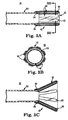
- FIGS. 1A-1C Prior to deployment ( FIG. 1A ), the stented prosthetic heart valve P is constrained within, and supports, the sheath S. With deployment ( FIG. 1B ), the sheath S is distally retracted, and the prosthesis P partially deploys.
- the prosthetic heart valve is radially self-expandable from a compressed arrangement to a natural arrangement.
- the delivery device includes an inner shaft assembly, a delivery sheath capsule, and a recapture sheath.
- the inner shaft assembly includes an intermediate region providing a coupling structure configured to selectively engage a stented prosthetic heart valve.
- the delivery sheath capsule is slidably disposed over the inner shaft assembly and is configured to compressively retain a stented prosthetic heart valve.
- the recapture sheath is slidably disposed over the inner shaft assembly and includes a funnel segment extending distally from a shaft.
- the funnel segment includes a plurality of circumferentially spaced runners and a polymer overlay.
- the runners are each attached at a first end to the shaft and terminate at a distal tip opposite the shaft.
- the polymer overlay surrounds the runners.
- the overlay is bonded to the shaft, but is not bonded to at least the distal tips.
- the funnel segment is transitionable from a natural condition to an expanded condition in which the funnel segment has a funnel shape with a distally increasing diameter. Further, the funnel segment is self-transitionable from the expanded condition toward the natural condition.
- the delivery device is configured to provide a delivery state in which the capsule compressively retains the stented prosthetic heart valve over the inner shaft assembly and the funnel segment is longitudinally displaced from the prosthetic heart valve.
- the funnel segment can be employed to facilitate sliding of the capsule over a partially deployed region of the prosthetic heart valve as part of a recapturing operation.
- the recapture sheath is provided apart from the delivery sheath capsule and is slidably disposed between the delivery sheath capsule and the inner shaft assembly.
- the funnel segment is formed as a distal extension from the delivery sheath capsule, with the funnel segment being located distal the prosthetic heart valve in the delivery state.
- the runners provide a columnar strength to the funnel segment, with the overlay controlling a shape of the funnel segment when subjected to an internal expansion force, such as when the funnel segment slides over a partially deployed prosthetic heart valve.
- the system includes a delivery device and a prosthetic heart valve.
- the delivery device includes the inner shaft assembly, the delivery sheath capsule, and the recapture sheath, including the funnel segment, as described above.
- the prosthetic heart valve has a stent frame and a valve structure forming at least two valve leaflets attached to the frame.
- the prosthetic heart valve is self-expandable from a compressed arrangement to a natural arrangement. With this construction, the system is configured to be transitionable between a loaded mode, a partially deployed mode, and a recapturing mode.
- the prosthetic heart valve is coupled to the intermediate region of the inner shaft assembly, with the capsule compressively retaining the prosthetic heart valve in the compressed arrangement.
- the funnel segment is longitudinally spaced from the prosthetic heart valve.
- the capsule is partially withdrawn from the prosthetic heart valve such that a distal region of the prosthetic heart valve is exposed relative to the capsule and self-expands.
- the funnel segment is positioned distal the capsule and along the distal exposed region of the prosthetic heart valve, causing the funnel segment to expand toward the expanded condition.
- the method includes receiving a delivery device loaded with a radially expandable prosthetic heart valve having a stent frame to which a valve structure is attached.
- the delivery device includes a delivery sheath capsule compressively containing the prosthetic heart valve in a compressed arrangement over an inner shaft assembly in a delivery state, as well as a recapture sheath including a funnel segment slidably disposed over the inner shaft assembly. In the delivery state, the funnel segment is longitudinally spaced from the prosthetic heart valve.
- the prosthetic heart valve is delivered, in the compressed arrangement, through a bodily lumen of the patient and to the implantation site via the delivery device in the delivery state.
- the capsule is proximally retracted relative to the prosthetic heart valve such that a distal region of the prosthetic heart valve is exposed distal the capsule.
- the exposed, distal region self-expands toward a natural arrangement.
- a position of the partially deployed prosthetic heart valve relative to the implantation site is evaluated. Based upon the evaluation, the recapture sheath is distally advanced relative to the prosthetic heart valve such that the funnel segment is distal the capsule and expands to a funnel shape in response to contact with the distal region of the prosthetic heart valve.
- the funnel segment is distally advanced over the distal region of the prosthetic heart valve.
- the capsule is then arranged over the prosthetic heart valve to cause the distal region to transition back toward the collapsed arrangement within the capsule.
- the capsule and the funnel segment are fully proximally retracted from the prosthetic heart valve such that the prosthetic heart valve deploys from the inner shaft assembly.
- the recapture sheath is slidably disposed within the delivery sheath such that recapturing of the partially deployed prosthetic heart valve includes sliding the funnel segment over the prosthetic heart valve, followed by sliding of the capsule over the funnel segment.
- the funnel segment is provided as a distal extension from the capsule such that recapturing of the prosthetic heart valve includes sliding of the funnel segment over the prosthetic heart valve sequentially followed by sliding of the capsule over the prosthetic heart valve.
- the device functions by providing a recapture sheath having a funnel segment that serves as a transition between the delivery sheath capsule and an expanded region of a partially deployed prosthesis to effectuate recapturing of the partially deployed prosthetic heart valve within the delivery sheath capsule.
- the stented prosthetic heart valve as used in accordance with the various systems, devices, and methods of the present disclosure may include a wide variety of different configurations, such as a bioprosthetic heart valve having tissue leaflets or a synthetic heart valve having a polymeric, metallic, or tissue-engineered leaflets, and can be specifically configured for replacing any heart valve.
- the stented prosthetic heart valve useful with the systems, devices, and methods of the present disclosure can be generally used for replacement of a native aortic, mitral, pulmonic, or tricuspid valve, for use as a venous valve, or to replace a failed bioprosthesis, such as in the area of an aortic valve or mitral valve, for example.
- the stented prosthetic heart valves of the present disclosure include a stent or stent frame maintaining a valve structure (tissue or synthetic), with the stent having a natural or normal, expanded arrangement and collapsible to a compressed arrangement for loading within the delivery device.
- the stent is normally constructed to self-deploy or self-expand when released from the delivery device.
- the stented prosthetic heart valve useful with the present disclosure can be a prosthetic valve sold under the trade name CoreValve® available from Medtronic CoreValve, LLC.
- Other non-limiting examples of transcatheter heart valve prostheses useful with systems, devices, and methods of the present disclosure are described in U.S. Publication Nos.
- the stents or stent frames are support structures that comprise a number of struts or wire portions arranged relative to each other to provide a desired compressibility and strength to the prosthetic heart valve.
- the stents or stent frames of the present disclosure are generally tubular support structures having an internal area in which valve structure leaflets will be secured.
- the leaflets can be formed from a verity of materials, such as autologous tissue, xenograph material, or synthetics as are known in the art.
- the leaflets may be provided as a homogenous, biological valve structure, such as porcine, bovine, or equine valves.
- the leaflets can be provided independent of one another (e.g., bovine or equine paracardial leaflets) and subsequently assembled to the support structure of the stent frame.
- the stent frame and leaflets can be fabricated at the same time, such as may be accomplished using high-strength nano-manufactured NiTi films produced at Advance BioProsthetic Surfaces (ABPS), for example.
- ABPS Advance BioProsthetic Surfaces
- the stent frame support structures are generally configured to accommodate at least two (typically three) leaftlets; however, replacement prosthetic heart valves of the types described herein can incorporate more or less than three leaflets.
- the stent frames can be a series of wires or wire segments arranged such that they are capable of self-transitioning from the compressed or collapsed arrangement to the normal, radially expanded arrangement.
- a number of individual wires comprising the stent frame support structure can be formed of a metal or other material. These wires are arranged in such a way that the stent frame support structure allows for folding or compressing or crimping to the compressed arrangement in which the internal diameter is smaller than the internal diameter when in the natural, expanded arrangement.
- a stent frame support structure with attached valves can be mounted onto a delivery device.
- the stent frame support structures are configured so that they can be changed to their natural, expanded arrangement when desired, such as by the relative movement of one or more sheaths relative to a length of the stent frame.
- the wires of the stent frame support structures in embodiments of the present disclosure can be formed from a shape memory material such as a nickel titanium alloy (e.g., NitinolTM). With this material, the support structure is self-expandable from the compressed arrangement to the natural, expanded arrangement, such as by the application of heat, energy, and the like, or by the removal of external forces (e.g., compressive forces).
- This stent frame support structure can also be compressed and re-expanded multiple times without damaging the structure of the stent frame.
- the stent frame support structure of such an embodiment may be laser-cut from a single piece of material or may be assembled from a number of different components.
- one example of a delivery device that can be used includes a catheter with a retractable sheath that covers the stent frame until it is to be deployed, at which point the sheath can be retracted to allow the stent frame to self-expand. Further details of such embodiments are discussed below.
- the device 30 generally includes a recapture sheath 32, an inner shaft assembly 34, a delivery sheath assembly 36, and a handle 38. Details on the various components are provided below. In general terms, however, the delivery device 30 combines with a stented prosthetic heart valve (not shown) to form a system for repairing (e.g., replacing) a defective heart valve of a patient.
- the delivery device 30 provides a delivery state in which the stented prosthetic heart valve is coupled to the inner shaft assembly 34 and compressively retained within a capsule 40 of the delivery sheath assembly 36.
- the delivery sheath assembly 36 can be manipulated to withdraw the capsule 40 proximally from the prosthetic heart valve via operation of the handle 38, permitting the prosthesis to self-expand (alternatively be caused to expand) and release from the inner shaft assembly 34. Further, the handle 38 can be operated to maneuver the recapture sheath 32 relative to the inner shaft assembly 34 and the delivery sheath assembly 36 to position a funnel segment 42 of the recapture sheath 32 distally beyond the capsule 40 and over a partially deployed region of the prosthetic heart valve to facilitate recapturing of the prosthesis within the capsule 40.
- delivery devices in accordance with the present disclosure provide features capable of compressively retaining a self-deploying, stented prosthetic heart valve (e.g., the capsule 40), a mechanism capable of effectuating release or deployment of the prosthesis (e.g., retracting the capsule 40), and a funneling-type structure (e.g., the funnel segment 42) that promotes recapture.
- a self-deploying, stented prosthetic heart valve e.g., the capsule 40
- a mechanism capable of effectuating release or deployment of the prosthesis e.g., retracting the capsule 40
- a funneling-type structure e.g., the funnel segment 42
- the recapture sheath 32 includes the funnel segment 42 and a shaft 50, with the funnel segment 42 extending distal the shaft 50.
- the recapture sheath 32 forms a lumen 52 (referenced generally) sized to be slidably received over the inner shaft assembly 34, with the recapture sheath 32 terminating at a distal end 54.
- the recapture sheath 32 is provided apart from the delivery sheath assembly 36, and is sized to be slidably received between the inner shaft assembly 34 and the delivery sheath assembly 36.
- the recapture sheath 32 is provided as part of the delivery sheath assembly 36, with the funnel segment 42 being formed as a distal extension from the capsule 40.
- the funnel segment 42 is configured to be radially expandable (e.g., in response to an internally applied, radially expansive force) from the normal or relaxed condition of FIG. 2 having a relatively small, relatively uniform diameter (e.g., akin to a uniform diameter cylinder or tube) to an expanded condition having a flange or funnel-like shape in which a diameter of the distal end 54 is radially increased (as compared to the normal condition).
- the funnel segment 42 Upon removal of the expansive force, the funnel segment 42 self-transitions from the expanded condition back to or toward the normal condition.
- the funnel segment 42 includes a plurality of circumferentially spaced runners 60 and a polymer overlay 62.
- a thickness of runners 60 and the overlay 62 is exaggerated in FIGS. 3A-3C for ease of explanation. Further the overlay 62 is illustrated as being transparent such that several of the runners 60 "behind” or within the overlay 62 in FIGS. 3A and 3C are visible.
- the runners 60 are identical in some constructions, each having a first end 64 attached to the shaft 50, and terminating at a distal tip 66 opposite the shaft 50.
- the polymer overlay 62 surrounds the runners 60, and controls transitioning or deflection of the runners 60 from the normal condition of FIGS. 3A and 3B to the expanded condition of FIG. 3C .
- the runners 60 impart a shape memory attribute to the funnel segment 42, and cause the funnel segment 42 to self-transition from the expanded condition of FIG. 3C toward the normal condition of FIG. 3A as described below.
- the runners 60 are, in some embodiments, formed as flexible metal strips, such as thin, stainless steel or NiTi strips.
- the shape and construction of the runners 60 are such that each of the runners 60 normally assumes a relatively linear or flat shape, for example via an imparted shape memory attribute.
- the first end 64 of each of the runners 60 can be attached to the shaft 50 in a variety of manners, such as adhesive bonding, welding, etc. Apart from the shaft 50 and the overlay 62, the runners 60 are not interconnected. Thus, the runners 60 can freely deflect relative to one another, and in particular at the respective distal tips 66, to the extent permitted by the overlay 62, deflecting at the point of attachment with the shaft 50.
- the funnel segment 42 can include two or more of the runners 60. In some embodiments, however, the funnel segment 42 includes at least four of the runners 60, with the runners 60 optionally being equidistantly spaced from one another about a circumference of the shaft 50. As shown, the distal tips 66 are, in some constructions, rounded, although other shapes are also envisioned. While the runners 60 can have a variety of differing dimensions, in some embodiments, each of the runners 60 has a thickness in the range of 0,13 mm - 0,38 mm (0.005 - 0.015 inch) and a length of extension from the shaft 50 to the corresponding distal tip 66 in the range of 5,1-25,4 mm (0.20 - 1.0 inch).
- the overlay 62 is a surgically safe, compliant polymeric material or film wrapped about the runners 60 and bonded to the shaft 50.
- the overlay 62 can be or include nylon or other amid block polymer, urethane, polyester, aliphatic polyamides, copolymers of polyether and polyamide, plasticized polyamides containing a sulfonamide plasticizer, thermoplastic polyether urethanes, low density or linear low density polyethylenes (that may or may not be cross-linked), etc.
- the overlay material(s) can be biaxially oriented.
- the overlay 62 can have a single, dual, or multi-layer construction. In some embodiments, the overlay 62 is not bonded to the runners 60 distal the shaft 50.
- the overlay 62 allows the runners 60 to freely deflect or expand within the overlay 62, collectively forming and supporting the funnel shape in the expanded condition of FIG. 3C . While the overlay 62 can be elastically deformable, the overlay 62 provides resistance to continued deflection of the runners 60 beyond a certain level of deflection. Thus, the overlay 62 controls the length and angle of taper defined by the funnel segment 62 in the funnel shape of the expanded condition. The runners 60, in turn, create a columnar strength within the overlay 62, while still allowing the overlay 62, and thus the funnel segment 42, to expand.
- the overlay 62 is initially provided as a thin-walled balloon that is inverted onto itself to encompass the runners 60.
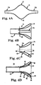
- FIGS. 4A-4D illustrate construction of the funnel segment 42 ( FIG. 3A ) in accordance with some embodiments of the present disclosure.
- a balloon 70 structure is formed or provided, having an intermediate section 72 and opposing first and second end sections 74a, 74b.
- the balloon structure 70 can be created, for example, by focused inflation of a polymer tube in a manner generating the intermediate section 72.
- the intermediate section 72 has enlarged inner and outer diameters as compared to the end sections 74a, 74b, tapering in diameter from a mid-point 76 to the end sections 74a, 74b.
- the end sections 74a, 74b are optionally sized to fit the inner and outer diameters, respectively, of the shaft 50 ( FIG. 3A ) to which the overlay 62 will be attached.
- the first end section 74a can be sized to approximate an outer diameter of a 16 French sheath
- the second end section 74b can be sized to approximate an inner diameter of a 16 French sheath (or vice-versa).
- the intermediate section 72 has a maximum diameter that is slightly larger than the outer diameter of the shaft 50 (e.g., where the shaft 50 is 16 French sheath, the maximum diameter of intermediate section 72 can be on the order 15-20 mm). Alternatively, other dimensions are also envisioned.
- the balloon structure 70 is then inverted or folded into itself as shown in FIG. 4B .
- the second end section 74b is directed axially toward the first end section 74a, causing the intermediate section 72 to invert onto itself at approximately the mid-point 76 ( FIG. 4A ).
- a location of the inversion is referenced at 78 in FIG. 4B .
- the inverted balloon structure 70 is then cut along a cut line 80.
- the cut line 80 is located along a length of the inverted balloon structure 70 that corresponds with the inner and outer diameters of the shaft 50 ( FIG. 3A ), for example where an inner diameter of the first end section 74a approximates an outer diameter of the shaft 50 and an outer diameter of the second end section 74b approximates an inner diameter of the shaft 50.
- the resultant overlay 62 is defined by inner and outer tubular walls 90, 92 arranged to define an open space 94 therebetween.
- the walls 90,92 extend from the inversion 78, with the inner wall 90 terminating at an inner end 96 having a diameter approximating an inner diameter of the shaft 50 ( FIG. 3A ) to which the overlay 62 is subsequently assembled.
- the outer wall 92 terminates at an outer end 98 opposite the inversion 78 and having a diameter approximating an outer diameter of the shaft 50.
- construction of the recapture sheath 32 includes the runners 60 attached to, and extending distally from, the shaft 50 as described above.
- the so-assembled runners 60 are then inserted into the open space 94 of the overlay 62.
- the overlay 62 is then bonded to the shaft 50.
- the inner wall 90 can be thermally bonded to the inner diameter of the shaft 50.
- the outer wall 92 can similarly be thermally bonded to an outer diameter of the shaft 50 and/or to the fist end 64 of each of the runners 60.
- the overlay 62 is not bonded to the runners 60 distal the shaft 50 in some embodiments. In other constructions, the overlay 62 may be bonded to a portion of one or more the runners 60 distal the shaft 50, but at least the distal tip 66 of each of the runners 60 is free of bonding to the overlay 62.
- the shaft 50 can assume any forms appropriate for supporting the funnel segment 42 in a manner facilitating desired sliding movement of the funnel segment 42 in response to movement of the shaft 50.
- the shaft 50 can be a thermoplastic elastomer tube, such as Pebax®, and optionally can include an embedded braided material layer (e.g., stainless steel wire).
- the recapture sheath 32 and in particular the funnel segment 42, can be alternatively constructed in various other manners.
- a thin-walled polymer tube can be wrapped about the runners 60.
- the funnel segment 42 is transitionable from the normal condition of FIG. 3A to the expanded condition (and corresponding funnel shape) of FIG. 3C in response to an internal expansive force, and then self-transition back toward the normal condition once the internal expansive force is removed due, at least in part, to a shape memory attribute collectively imparted into the funnel segment 42 by the runners 60.
- the remaining components 34-38 of the delivery device 30 can assume a variety of forms appropriate for percutaneously delivering and deploying a stented self-expanding prosthetic heart valve.
- the inner shaft assembly 34 can have various constructions appropriate for supporting a stented prosthetic heart valve within the capsule 40.
- the inner shaft assembly 34 can include a retention member 100, an intermediate tube 102, and a proximal tube 104.
- the retention member 100 can be akin to a plunger, and incorporates features for retaining the stented prosthetic heart valve within the capsule 40 as described below.
- the tube 102 connects the retention member 100 to the proximal tube 104, with the proximal tube 104, in turn, coupling the inner shaft assembly 34 with the handle 38.
- the components 100-104 can combine to define a continuous lumen 106 (referenced generally) sized to slidably receive an auxiliary component such as a guide wire (not shown).
- the retention member 100 can include a tip 110, a support tube 112, and a hub 114.
- the tip 110 forms or defines a nose cone having a distally tapering outer surface adapted to promote atraumatic contact with bodily tissue.
- the tip 110 can be fixed or slidable relative to the support tube 112.
- the support tube 112 extends proximally from the tip 110 and is configured to internally support a compressed, stented prosthetic heart valve generally disposed thereover, and has a length and outer diameter corresponding with dimensional attributes of the selected prosthetic heart valve.
- the hub 114 is attached to the support tube 112 opposite the tip 110 (e.g., an adhesive bond), and provides a coupling structure 120 (referenced generally) configured to selectively capture a corresponding feature of the prosthetic heart valve.
- the coupling structure 120 can assume various forms, and is generally located along an intermediate portion of the inner shaft assembly 34.
- the coupling structure 120 includes one or more fingers sized to be received within corresponding apertures formed by the prosthetic heart valve stent frame (e.g., the prosthetic heart valve stent frame can form wire loops at a proximal end thereof that are received over respective ones of the fingers when compressed within the capsule 40).
- Other releasable coupling arrangements are also acceptable, such as the hub 114 forming one or more slots sized to slidably receive a corresponding component(s) of the prosthetic heart valve (e.g., a bar or leg segment of the stent frame).
- the inner shaft assembly 34 can incorporate additional structures and/or mechanisms that assist in temporarily retaining the stented valve (e.g., a tubular sleeve biased over the coupling structure 120), such as described in U.S. Provisional Application Serial No. 61/237,373 entitled “Transcatheter Valve Delivery Systems and Methods” filed August 27, 2009.
- the intermediate tube 102 is formed of a flexible polymer material (e.g., PEEK), and is sized to be slidably received within the delivery sheath assembly 36.
- the proximal tube 104 can include, in some embodiments, a leading portion 122 and a trailing portion 124.
- the leading portion 122 serves as a transition between the intermediate and proximal tubes 102, 104 and thus in some embodiments is a flexible polymer tubing (e.g., PEEK) having a diameter slightly less than that of the intermediate tube 102.
- the trailing portion 124 has a more rigid construction, configured for robust assembly with the handle 38 such as a metal hypotube. Other constructions are also envisioned.
- the intermediate and proximal tubes 102, 104 are integrally formed as a single, homogenous tube or solid shaft.
- the delivery sheath assembly 36 includes the capsule 40 and a delivery sheath shaft 130, and defines proximal and distal ends 132, 134.
- the capsule 40 extends distally from the delivery shaft 130, and in some embodiments has a more stiffened construction (as compared to a stiffness of the delivery shaft 130) that exhibits sufficient radial or circumferential rigidity to overtly resist the expected expansive forces of the stented prosthetic heart valve in the compressed arrangement.
- the delivery shaft 130 can be a polymer tube embedded with a metal braiding
- the capsule 40 is a laser-cut metal tube that is optionally embedded within a polymer covering.
- the capsule 40 and the delivery shaft 130 can have a more uniform construction (e.g., a continuous polymer tube).
- the capsule 40 is constructed to compressively retain the stented prosthetic heart valve at a predetermined diameter when loaded within the capsule 40, and the delivery shaft 130 serves to connect the capsule 40 with the handle 38.
- the delivery shaft 130 (as well as the capsule 40) is constructed to be sufficiently flexible for passage through a patient's vasculature, yet exhibit sufficient longitudinal rigidity to effectuate desired axial movement of the capsule 40.
- proximal retraction of the delivery shaft 130 is directly transferred to the capsule 40 and causes a corresponding proximal retraction of the capsule 40.
- the delivery shaft 130 is further configured to transmit a rotational force or movement onto the capsule 40.
- the handle 38 generally includes a housing 140 and one or more actuator mechanisms 142 (referenced generally).
- the housing 140 maintains the actuator mechanism(s) 142, with the handle 38 configured to facilitate sliding movement of the delivery sheath assembly 36 relative to the recapture sheath 32 and the inner shaft assembly 34, as well as the recapture sheath 32 relative to the inner shaft assembly 34 and the delivery sheath assembly 36.
- the housing 140 can have any shape or size appropriate for convenient handling by a user.
- a first, deployment actuator mechanism 142a includes a user interface or actuator 144 slidably retained by the housing 140 and coupled to a delivery sheath connector body 146.
- the proximal end 132 of the delivery sheath assembly 36 is connected to the delivery sheath connector body 146.
- the inner shaft assembly 34 and in particular the proximal tube 104, is slidably received within a passage 148 (referenced generally) of the delivery sheath connector body 146, and is rigidly coupled to the housing 140.
- a second, recapture actuator mechanism 142b similarly includes a user interface or actuator 150 moveably maintained by the housing 140 and coupled to the recapture sheath 32 via one or more bodies (not shown) facilitating movement of the recapture sheath 32 with operation of the recapture actuator 150.
- the deployment actuator 144 can be operated to effectuate axial movement of the delivery sheath assembly 36 relative to the recapture sheath 32 and the inner shaft assembly 34.
- the recapture actuator 150 can be manipulated to axially slide the recapture sheath 32 relative to the inner shaft assembly 34 and the delivery sheath assembly 36.
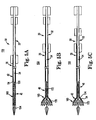
- FIG. 5A illustrates, in simplified form, a system 158 in accordance with the present disclosure for restoring (e.g., replacing or repairing) a defective heart valve of a patient and including a stented prosthetic heart valve 160 loaded within the delivery device 30.
- the prosthetic heart valve 160 is crimped over the inner shaft assembly 34, such that the prosthetic heart valve 160 engages the coupling structure 120.
- the capsule 40 compressively contains the prosthetic heart valve 160 in the compressed arrangement shown to define a loaded mode of the system 158 (it being understood that the "loaded mode" of the system 158 corresponds with the delivery device 30 in the delivery state).
- the distal end 54 of the recapture sheath 32 is longitudinally spaced from the prosthetic heart valve 160, with the funnel segment 42 assuming the normal condition described above.
- the recapture sheath distal end 54 is proximally spaced from the prosthetic heart valve 160.
- the capsule 40 exhibits sufficient structural integrity to compressively maintain the prosthetic heart valve 160 in the compressed arrangement without the funnel segment 42, or any other portion of the recapture sheath 32, being disposed over the prosthetic heart valve 160 in the loaded mode.
- the delivery sheath assembly 36 is withdrawn from over the prosthetic heart valve 160, for example by proximally retracting the capsule 40, such that the capsule distal end 134 is proximal the coupling structure 120. Once the capsule 40 is proximal the coupling structure 120, the prosthetic heart valve 160 is allowed to self-expand to the natural arrangement thereby releasing from the delivery device 30.
- a clinician may desire to only partially deploy the prosthetic heart valve 160 from the delivery device 30 and then evaluate before fully releasing the prosthetic heart valve 160.
- the delivery device 30 loaded with the prosthetic heart valve 160 can be employed as part of a method to repair a damaged heart valve of a patient.
- the delivery device 30, in the delivery state is advanced toward the native heart valve implantation target site, for example in a retrograde approach, through a cut-down to the femoral artery and into the patient's descending aorta.
- the delivery device 30 is then advanced, under fluoroscopic guidance, over the aortic arch, through the ascending aorta, and midway across the defective aortic valve (for aortic valve replacement).
- the delivery sheath assembly 36 is partially retracted relative to the prosthetic heart valve 160 as shown in FIG. 5B .
- a distal region 170 of the prosthesis 160 is thus exteriorly exposed relative to the capsule 40 and self-expands.
- at least a proximal region 172 of the prosthesis 160 remains within the confines of the capsule 40, and thus coupled to the delivery device 30.
- a position of the stented prosthetic heart valve 160 relative to the desired implantation site can again be evaluated.
- the prosthetic heart valve 160 must first be contracted and "resheathed" by transitioning the delivery device 30 to a recapturing state (and thus of the system 158 to a recapturing mode).
- the recapture sheath 32 is distally advanced relative to the delivery sheath assembly 36.
- the funnel segment 42 is distally advanced beyond the distal end 134 of the capsule 40, and maneuvered into contact with the exposed distal region 170 of the prosthetic heart valve 160.
- the overlay 62 ( FIG.
- the funnel segment 42 readily slides along a surface of the prosthetic heart valve 160, with the distal end 54 gently engaging the distal region (due, at least in part, to the thin wall thickness and expansibility of the distal end 54). Further, as the funnel segment 42 contacts or interfaces with the distally expanding diameter rigidly defined by the distal region 170, the funnel segment 42 transitions to the expanded condition.
- the runners 60 FIGS. 3A-3C ) deflect radially outwardly in response to an interface between the distal tips 66 ( FIG. 3A ) and the enlarged diameter distal region 170 of the prosthetic heart valve 160. Stated otherwise, the distal region 170 generates an internal expansive force within the funnel segment 42.
- the overlay 62 generally permits necessary deflection to accommodate a diameter of the prosthetic heart valve 160, but generally controls or maintains the funnel segment 42 to a funnel shape.
- Distal advancement of the funnel segment 42 continues along approximately an entirety of the prosthetic heart valve 160 as shown in FIG. 5D . While the distal region 170 may or may not slightly compress in response to placement within the funnel segment 42, complete compression of the prosthetic heart valve 160 does not occur. Instead, as shown in FIG. 5E , the delivery sheath assembly 36 is subsequently distally advanced, with the capsule 40 sliding over and along the funnel segment 42. The funnel segment 42 effectively serves to physical isolate the capsule 40 from directly contacting the prosthetic heart valve 160. As a result, the distal end 134 of the capsule 40 does not abruptly contact the prosthetic heart valve 160 in a manner that might otherwise cause the capsule 40 to buckle or collapse.
- the capsule 40 overcomes the radial force of the distal region 170 and acts to radially compress the previously-expanded distal region 170, forcing the prosthetic heart valve 160 back to approximately the initial, collapsed arrangement as shown in FIG. 5E .
- the delivery device 30 can be repositioned relative to the implantation site, and the process repeated until the clinician is comfortable with the achieved positioning.
- the resheathed stented prosthetic heart valve 160 can be removed from the patient.
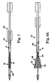
- FIG. 6 illustrates an alternative delivery sheath assembly 200 useful with a percutaneous prosthetic heart valve delivery device in accordance with principles of the present disclosure.
- the delivery sheath assembly includes the capsule 40 and the delivery sheath shaft 130 as described above with respect to the delivery sheath assembly 36 ( FIG. 2 ).
- a recapture sheath 202 is attached to, and extends distally from, a distal end 204 the capsule 40.
- the recapture sheath 202 can assume any of the forms described above with respect to the recapture sheath 32 ( FIG. 2 ), and generally includes a funnel segment 206.
- the funnel segment 206 is configured to have a normal or relaxed condition characterized by a substantially cylindrical shape, and is transitionable to an expanded condition characterized by a funnel-like shape having a distally increasing diameter. Further, the funnel segment 206 is configured to self-transition from the expanded condition back to or toward the normal condition.
- the funnel segment 206 can include a plurality of circumferentially spaced runners 209 (akin to the runners 60 of FIGS. 3A-3C ) surrounded by a polymer overlay 210 (akin to the overlay 62 of FIGS. 3A-3C ) as described above, with the runners 208 collectively imparting a shape memory attribute to the funnel segment 206 toward the normal condition.
- FIG. 7 illustrates the delivery sheath assembly 200 as part of a delivery device 220 loaded with the prosthetic heart valve 160 to define a system for repairing (e.g., replacing) a defective valve.
- the capsule 40 is disposed over the prosthetic heart valve 160, compressively retaining the prosthetic heart valve 160 in crimped engagement with the inner shaft assembly 34 as described above.
- the funnel segment 206 is longitudinally spaced from the prosthetic heart valve 160.
- the delivery state of the delivery device 220 i.e., the loaded mode of the repair system
- the delivery state of the delivery device 220 includes the funnel segment 206 being located distal the prosthetic heart valve 160.
- the shape memory feature imparted to the funnel segment 206 causes the funnel segment 206 to naturally retain the reduced diameter normal condition illustrated.
- Partial deployment of the prosthetic heart valve 160 from the delivery device 220 is illustrated in FIG. 8A , and includes partially withdrawing the capsule 40 from the prosthetic heart valve 160.
- the capsule 40 is proximally retracted.
- the funnel segment 206 simultaneously moved proximally with retraction of the delivery sheath assembly 200.
- a distal region 222 of the prosthetic heart valve 160 distal the distal end 204 capsule 40 is no longer compressively constrained by the capsule 40, and begins to self-expand.
- the funnel segment 206 does not overtly resist or impede this expansion. Instead, the runnel segment 206 expands (i.e., is forcibly transitioned to the expanded condition) to a shape generally corresponding with that of the deploying distal region 222.
- the prosthetic heart valve 160 can be resheathed or recaptured within the capsule 40 by distally advancing the delivery sheath assembly 200 as generally reflected by the recapturing state of the delivery device 220 in FIG. 8B .
- the funnel segment 206 in the expanded condition, readily slides along an exterior of the prosthetic heart valve 160, and effectively serves as a buffer between the structure of the prosthetic heart valve 160 and the stiff, distal end 204 of the capsule 40.
- the capsule 40 will not buckle as it is advanced over the distal region 222, nor will the capsule 40 damage the prosthetic heart valve 160.
- the prosthetic heart valve 160 is forcibly compressed back to the initial, compressed arrangement ( FIG. 8A ).
- the shape memory attribute causes the funnel segment 206 to self-transition back toward the reduced diameter, normal condition.
- the delivery devices shown and described herein can be modified for delivery of balloon-expandable stented prosthetic heart valves, within the scope of the present disclosure. That is to say, delivering balloon-expandable stents to an implantation location can be performed percutaneously using modified versions of the delivery devices of the present disclosure. In general terms, this includes providing a transcatheter assembly that can include a delivery sheath and/or additional sheaths as described above.
- the devices would further include a delivery catheter, a balloon catheter, and/or a guide wire.
- a delivery catheter used in this type of delivery device defines a lumen within which the balloon catheter is received.
- the balloon catheter in turn, defines a lumen within which the guide wire is slidably disposed.
- the balloon catheter includes a balloon that is fluidly connected to an inflation source.
- the transcatheter assembly With the stented valve mounted to the balloon, the transcatheter assembly is delivered through a percutaneous opening in the patient via the delivery device. Once the stented prosthetic heart valve is properly positioned, the balloon catheter is operated to inflate the balloon, thus transitioning the stented prosthesis to an expanded arrangement.
- the systems, devices, and methods of the present disclosure provide a marked improvement over previous designs.
- an expandable recapture sheath apart from the delivery sheath capsule otherwise utilized to compressively retain the stented prosthetic heart valve a partially deployed prosthesis is more readily recaptured.
Landscapes
- Health & Medical Sciences (AREA)
- Cardiology (AREA)
- Engineering & Computer Science (AREA)
- Biomedical Technology (AREA)
- Heart & Thoracic Surgery (AREA)
- Transplantation (AREA)
- Oral & Maxillofacial Surgery (AREA)
- Vascular Medicine (AREA)
- Life Sciences & Earth Sciences (AREA)
- Animal Behavior & Ethology (AREA)
- General Health & Medical Sciences (AREA)
- Public Health (AREA)
- Veterinary Medicine (AREA)
- Prostheses (AREA)
Applications Claiming Priority (2)
| Application Number | Priority Date | Filing Date | Title |
|---|---|---|---|
| US12/758,443 US8512401B2 (en) | 2010-04-12 | 2010-04-12 | Transcatheter prosthetic heart valve delivery system with funnel recapturing feature and method |
| PCT/US2011/031586 WO2011130093A1 (en) | 2010-04-12 | 2011-04-07 | Transcatheter prosthetic heart valve delivery device with funnel recapturing feature and method |
Publications (2)
| Publication Number | Publication Date |
|---|---|
| EP2558030A1 EP2558030A1 (en) | 2013-02-20 |
| EP2558030B1 true EP2558030B1 (en) | 2015-07-22 |
Family
ID=44246981
Family Applications (1)
| Application Number | Title | Priority Date | Filing Date |
|---|---|---|---|
| EP11715810.5A Not-in-force EP2558030B1 (en) | 2010-04-12 | 2011-04-07 | Transcatheter prosthetic heart valve delivery device with funnel recapturing feature |
Country Status (6)
| Country | Link |
|---|---|
| US (2) | US8512401B2 (enExample) |
| EP (1) | EP2558030B1 (enExample) |
| JP (1) | JP5846395B2 (enExample) |
| CN (1) | CN102892384A (enExample) |
| AU (1) | AU2011240939B2 (enExample) |
| WO (1) | WO2011130093A1 (enExample) |
Cited By (15)
| Publication number | Priority date | Publication date | Assignee | Title |
|---|---|---|---|---|
| US10856984B2 (en) | 2017-08-25 | 2020-12-08 | Neovasc Tiara Inc. | Sequentially deployed transcatheter mitral valve prosthesis |
| US10940001B2 (en) | 2012-05-30 | 2021-03-09 | Neovasc Tiara Inc. | Methods and apparatus for loading a prosthesis onto a delivery system |
| US11311376B2 (en) | 2019-06-20 | 2022-04-26 | Neovase Tiara Inc. | Low profile prosthetic mitral valve |
| US11357622B2 (en) | 2016-01-29 | 2022-06-14 | Neovase Tiara Inc. | Prosthetic valve for avoiding obstruction of outflow |
| US11389291B2 (en) | 2013-04-04 | 2022-07-19 | Neovase Tiara Inc. | Methods and apparatus for delivering a prosthetic valve to a beating heart |
| US11413139B2 (en) | 2011-11-23 | 2022-08-16 | Neovasc Tiara Inc. | Sequentially deployed transcatheter mitral valve prosthesis |
| US11419720B2 (en) | 2010-05-05 | 2022-08-23 | Neovasc Tiara Inc. | Transcatheter mitral valve prosthesis |
| US11464631B2 (en) | 2016-11-21 | 2022-10-11 | Neovasc Tiara Inc. | Methods and systems for rapid retraction of a transcatheter heart valve delivery system |
| US11491006B2 (en) | 2019-04-10 | 2022-11-08 | Neovasc Tiara Inc. | Prosthetic valve with natural blood flow |
| US11497602B2 (en) | 2012-02-14 | 2022-11-15 | Neovasc Tiara Inc. | Methods and apparatus for engaging a valve prosthesis with tissue |
| US11602429B2 (en) | 2019-04-01 | 2023-03-14 | Neovasc Tiara Inc. | Controllably deployable prosthetic valve |
| US11737872B2 (en) | 2018-11-08 | 2023-08-29 | Neovasc Tiara Inc. | Ventricular deployment of a transcatheter mitral valve prosthesis |
| US11779742B2 (en) | 2019-05-20 | 2023-10-10 | Neovasc Tiara Inc. | Introducer with hemostasis mechanism |
| US11998447B2 (en) | 2019-03-08 | 2024-06-04 | Neovasc Tiara Inc. | Retrievable prosthesis delivery system |
| US12109111B2 (en) | 2015-12-15 | 2024-10-08 | Neovasc Tiara Inc. | Transseptal delivery system |
Families Citing this family (247)
| Publication number | Priority date | Publication date | Assignee | Title |
|---|---|---|---|---|
| JP3459292B2 (ja) | 1994-02-28 | 2003-10-20 | 東プレ株式会社 | C型スポット溶接ガン装置 |
| WO2005074367A2 (en) | 2004-02-03 | 2005-08-18 | Atria Medical Inc. | Device and method for controlling in-vivo pressure |
| US8308797B2 (en) | 2002-01-04 | 2012-11-13 | Colibri Heart Valve, LLC | Percutaneously implantable replacement heart valve device and method of making same |
| JP2008513060A (ja) | 2004-09-14 | 2008-05-01 | エドワーズ ライフサイエンシーズ アーゲー | 心臓弁逆流の処置のためのデバイスおよび方法 |
| DE102005003632A1 (de) | 2005-01-20 | 2006-08-17 | Fraunhofer-Gesellschaft zur Förderung der angewandten Forschung e.V. | Katheter für die transvaskuläre Implantation von Herzklappenprothesen |
| US8038704B2 (en) * | 2005-07-27 | 2011-10-18 | Paul S. Sherburne | Stent and other objects removal from a body |
| EP1951352B1 (en) | 2005-11-10 | 2017-01-11 | Edwards Lifesciences CardiAQ LLC | Balloon-expandable, self-expanding, vascular prosthesis connecting stent |
| US9681948B2 (en) | 2006-01-23 | 2017-06-20 | V-Wave Ltd. | Heart anchor device |
| US7896915B2 (en) | 2007-04-13 | 2011-03-01 | Jenavalve Technology, Inc. | Medical device for treating a heart valve insufficiency |
| DE102007043830A1 (de) | 2007-09-13 | 2009-04-02 | Lozonschi, Lucian, Madison | Herzklappenstent |
| US9044318B2 (en) | 2008-02-26 | 2015-06-02 | Jenavalve Technology Gmbh | Stent for the positioning and anchoring of a valvular prosthesis |
| ES2903231T3 (es) | 2008-02-26 | 2022-03-31 | Jenavalve Tech Inc | Stent para el posicionamiento y anclaje de una prótesis valvular en un sitio de implantación en el corazón de un paciente |
| US20090276040A1 (en) | 2008-05-01 | 2009-11-05 | Edwards Lifesciences Corporation | Device and method for replacing mitral valve |
| EP2367505B1 (en) | 2008-09-29 | 2020-08-12 | Edwards Lifesciences CardiAQ LLC | Heart valve |
| WO2010121076A2 (en) | 2009-04-15 | 2010-10-21 | Cardiaq Valve Technologies, Inc. | Vascular implant and delivery system |
| NZ624106A (en) | 2009-04-29 | 2015-12-24 | Cleveland Clinic Foundation | Apparatus and method for replacing a diseased cardiac valve |
| US12453626B2 (en) | 2009-05-04 | 2025-10-28 | V-Wave Ltd. | Shunt for redistributing atrial blood volume |
| US12186176B2 (en) | 2009-05-04 | 2025-01-07 | V-Wave Ltd. | Shunt for redistributing atrial blood volume |
| EP2427143B1 (en) | 2009-05-04 | 2017-08-02 | V-Wave Ltd. | Device for regulating pressure in a heart chamber |
| US9730790B2 (en) | 2009-09-29 | 2017-08-15 | Edwards Lifesciences Cardiaq Llc | Replacement valve and method |
| US8449599B2 (en) | 2009-12-04 | 2013-05-28 | Edwards Lifesciences Corporation | Prosthetic valve for replacing mitral valve |
| EP3838223B1 (en) | 2009-12-08 | 2025-08-20 | Avalon Medical Ltd. | Device and system for transcatheter mitral valve replacement |
| US8870950B2 (en) | 2009-12-08 | 2014-10-28 | Mitral Tech Ltd. | Rotation-based anchoring of an implant |
| WO2011111047A2 (en) | 2010-03-10 | 2011-09-15 | Mitraltech Ltd. | Prosthetic mitral valve with tissue anchors |
| AU2011248657B2 (en) * | 2010-04-27 | 2014-12-04 | Medtronic Inc. | Transcatheter prosthetic heart valve delivery device with passive trigger release |
| CN102917668B (zh) * | 2010-04-27 | 2015-01-28 | 美敦力公司 | 具有偏置释放结构的经导管假体心脏瓣膜输送装置 |
| US10856978B2 (en) | 2010-05-20 | 2020-12-08 | Jenavalve Technology, Inc. | Catheter system |
| US11278406B2 (en) | 2010-05-20 | 2022-03-22 | Jenavalve Technology, Inc. | Catheter system for introducing an expandable heart valve stent into the body of a patient, insertion system with a catheter system and medical device for treatment of a heart valve defect |
| JP2013526388A (ja) | 2010-05-25 | 2013-06-24 | イエナバルブ テクノロジー インク | 人工心臓弁、及び人工心臓弁とステントを備える経カテーテル搬送体内プロテーゼ |
| JP6125999B2 (ja) | 2010-06-21 | 2017-05-10 | カルディアック バルブ テクノロジーズ,インコーポレーテッド | 人工心臓弁 |
| US9119738B2 (en) | 2010-06-28 | 2015-09-01 | Colibri Heart Valve Llc | Method and apparatus for the endoluminal delivery of intravascular devices |
| US9763657B2 (en) | 2010-07-21 | 2017-09-19 | Mitraltech Ltd. | Techniques for percutaneous mitral valve replacement and sealing |
| US8992604B2 (en) | 2010-07-21 | 2015-03-31 | Mitraltech Ltd. | Techniques for percutaneous mitral valve replacement and sealing |
| US9132009B2 (en) | 2010-07-21 | 2015-09-15 | Mitraltech Ltd. | Guide wires with commissural anchors to advance a prosthetic valve |
| US11653910B2 (en) | 2010-07-21 | 2023-05-23 | Cardiovalve Ltd. | Helical anchor implantation |
| CN103025277B (zh) * | 2010-07-21 | 2015-05-20 | 库克医学技术有限责任公司 | 用于支架递送系统的控制系统 |
| EP3459500B1 (en) | 2010-09-23 | 2020-09-16 | Edwards Lifesciences CardiAQ LLC | Replacement heart valves and delivery devices |
| AU2011343755A1 (en) | 2010-12-14 | 2013-06-06 | Colibri Heart Valve Llc | Percutaneously deliverable heart valve including folded membrane cusps with integral leaflets |
| US11135054B2 (en) | 2011-07-28 | 2021-10-05 | V-Wave Ltd. | Interatrial shunts having biodegradable material, and methods of making and using same |
| AU2012209013B2 (en) * | 2011-08-02 | 2013-11-14 | Cook Medical Technologies Llc | Delivery device having a variable diameter introducer sheath |
| US20140324164A1 (en) | 2011-08-05 | 2014-10-30 | Mitraltech Ltd. | Techniques for percutaneous mitral valve replacement and sealing |
| WO2013021374A2 (en) | 2011-08-05 | 2013-02-14 | Mitraltech Ltd. | Techniques for percutaneous mitral valve replacement and sealing |
| US8852272B2 (en) | 2011-08-05 | 2014-10-07 | Mitraltech Ltd. | Techniques for percutaneous mitral valve replacement and sealing |
| WO2013021375A2 (en) | 2011-08-05 | 2013-02-14 | Mitraltech Ltd. | Percutaneous mitral valve replacement and sealing |
| WO2013028387A2 (en) | 2011-08-11 | 2013-02-28 | Tendyne Holdings, Inc. | Improvements for prosthetic valves and related inventions |
| US10010437B2 (en) | 2011-10-17 | 2018-07-03 | W. L. Gore & Associates, Inc. | Endoluminal device retrieval devices and related systems and methods |
| US9827092B2 (en) | 2011-12-16 | 2017-11-28 | Tendyne Holdings, Inc. | Tethers for prosthetic mitral valve |
| WO2014022124A1 (en) | 2012-07-28 | 2014-02-06 | Tendyne Holdings, Inc. | Improved multi-component designs for heart valve retrieval device, sealing structures and stent assembly |
| US9675454B2 (en) | 2012-07-30 | 2017-06-13 | Tendyne Holdings, Inc. | Delivery systems and methods for transcatheter prosthetic valves |
| US9433521B2 (en) | 2012-11-27 | 2016-09-06 | Medtronic, Inc. | Distal tip for a delivery catheter |
| US20150351906A1 (en) | 2013-01-24 | 2015-12-10 | Mitraltech Ltd. | Ventricularly-anchored prosthetic valves |
| US9439763B2 (en) | 2013-02-04 | 2016-09-13 | Edwards Lifesciences Corporation | Prosthetic valve for replacing mitral valve |
| US9339385B2 (en) * | 2013-03-07 | 2016-05-17 | St. Jude Medical, Cardiology Division, Inc. | Balloon release mechanism for TAVI implant |
| US10583002B2 (en) | 2013-03-11 | 2020-03-10 | Neovasc Tiara Inc. | Prosthetic valve with anti-pivoting mechanism |
| US20140277427A1 (en) | 2013-03-14 | 2014-09-18 | Cardiaq Valve Technologies, Inc. | Prosthesis for atraumatically grasping intralumenal tissue and methods of delivery |
| US9681951B2 (en) | 2013-03-14 | 2017-06-20 | Edwards Lifesciences Cardiaq Llc | Prosthesis with outer skirt and anchors |
| US9730791B2 (en) | 2013-03-14 | 2017-08-15 | Edwards Lifesciences Cardiaq Llc | Prosthesis for atraumatically grasping intralumenal tissue and methods of delivery |
| EP2967807B1 (en) | 2013-03-14 | 2020-07-22 | Valve Medical Ltd. | Temporary valve |
| WO2014162306A2 (en) * | 2013-04-02 | 2014-10-09 | Tendyne Holdings, Inc. | Improved devices and methods for transcatheter prosthetic heart valves |
| US9486306B2 (en) | 2013-04-02 | 2016-11-08 | Tendyne Holdings, Inc. | Inflatable annular sealing device for prosthetic mitral valve |
| US10463489B2 (en) | 2013-04-02 | 2019-11-05 | Tendyne Holdings, Inc. | Prosthetic heart valve and systems and methods for delivering the same |
| US11224510B2 (en) | 2013-04-02 | 2022-01-18 | Tendyne Holdings, Inc. | Prosthetic heart valve and systems and methods for delivering the same |
| US10478293B2 (en) | 2013-04-04 | 2019-11-19 | Tendyne Holdings, Inc. | Retrieval and repositioning system for prosthetic heart valve |
| EP2999412B1 (en) | 2013-05-21 | 2020-05-06 | V-Wave Ltd. | Apparatus for delivering devices for reducing left atrial pressure |
| US9610159B2 (en) | 2013-05-30 | 2017-04-04 | Tendyne Holdings, Inc. | Structural members for prosthetic mitral valves |
| US9788943B2 (en) | 2013-06-11 | 2017-10-17 | Medtronic, Inc. | Delivery system with inline sheath |
| EP2813195A1 (en) * | 2013-06-13 | 2014-12-17 | Cardiatis S.A. | Stent delivery system |
| EP3007648B1 (en) | 2013-06-14 | 2019-11-13 | Avantec Vascular Corporation | Inferior vena cava filter and retrieval systems |
| CA2914856C (en) | 2013-06-25 | 2021-03-09 | Chad Perrin | Thrombus management and structural compliance features for prosthetic heart valves |
| US9237948B2 (en) * | 2013-07-11 | 2016-01-19 | Medtronic, Inc. | Delivery system with projections |
| JP6465883B2 (ja) | 2013-08-01 | 2019-02-06 | テンダイン ホールディングス,インコーポレイテッド | 心外膜アンカーデバイス及び方法 |
| WO2015028209A1 (en) | 2013-08-30 | 2015-03-05 | Jenavalve Technology Gmbh | Radially collapsible frame for a prosthetic valve and method for manufacturing such a frame |
| WO2015058039A1 (en) | 2013-10-17 | 2015-04-23 | Robert Vidlund | Apparatus and methods for alignment and deployment of intracardiac devices |
| AU2014342935B2 (en) | 2013-10-28 | 2019-05-16 | Tendyne Holdings, Inc. | Prosthetic heart valve and systems and methods for delivering the same |
| US9526611B2 (en) | 2013-10-29 | 2016-12-27 | Tendyne Holdings, Inc. | Apparatus and methods for delivery of transcatheter prosthetic valves |
| WO2015120122A2 (en) | 2014-02-05 | 2015-08-13 | Robert Vidlund | Apparatus and methods for transfemoral delivery of prosthetic mitral valve |
| US9986993B2 (en) | 2014-02-11 | 2018-06-05 | Tendyne Holdings, Inc. | Adjustable tether and epicardial pad system for prosthetic heart valve |
| CN106170269B (zh) | 2014-02-21 | 2019-01-11 | 爱德华兹生命科学卡迪尔克有限责任公司 | 用于瓣膜替代品的受控部署的递送装置 |
| USD755384S1 (en) | 2014-03-05 | 2016-05-03 | Edwards Lifesciences Cardiaq Llc | Stent |
| CA2937566C (en) | 2014-03-10 | 2023-09-05 | Tendyne Holdings, Inc. | Devices and methods for positioning and monitoring tether load for prosthetic mitral valve |
| US10149758B2 (en) | 2014-04-01 | 2018-12-11 | Medtronic, Inc. | System and method of stepped deployment of prosthetic heart valve |
| US20150328000A1 (en) | 2014-05-19 | 2015-11-19 | Cardiaq Valve Technologies, Inc. | Replacement mitral valve with annular flap |
| US9532870B2 (en) | 2014-06-06 | 2017-01-03 | Edwards Lifesciences Corporation | Prosthetic valve for replacing a mitral valve |
| EP4066786B1 (en) | 2014-07-30 | 2025-05-14 | Cardiovalve Ltd. | Articulatable prosthetic valve |
| CN106852115A (zh) | 2014-09-28 | 2017-06-13 | 卡迪欧凯尼迪克斯公司 | 用于治疗心功能不全的装置 |
| US10314634B2 (en) | 2014-11-04 | 2019-06-11 | Avantec Vascular Corporation | Catheter device with longitudinally expanding interior components for compressing cancellous bone |
| EP4410245A3 (en) | 2014-11-26 | 2024-10-16 | Edwards Lifesciences Corporation | Transcatheter prosthetic heart valve and delivery system |
| US9693860B2 (en) | 2014-12-01 | 2017-07-04 | Medtronic, Inc. | Segmented transcatheter valve prosthesis having an unsupported valve segment |
| EP3229729B1 (en) * | 2014-12-12 | 2023-03-15 | Avantec Vascular Corporation | Ivc filter retrieval systems with interposed support members |
| US10278804B2 (en) | 2014-12-12 | 2019-05-07 | Avantec Vascular Corporation | IVC filter retrieval systems with releasable capture feature |
| CA2972966C (en) | 2015-01-07 | 2023-01-10 | Tendyne Holdings, Inc. | Prosthetic mitral valves and apparatus and methods for delivery of same |
| US10159587B2 (en) * | 2015-01-16 | 2018-12-25 | Boston Scientific Scimed, Inc. | Medical device delivery system with force reduction member |
| US10478297B2 (en) | 2015-01-27 | 2019-11-19 | Medtronic Vascular, Inc. | Delivery system having an integral centering mechanism for positioning a valve prosthesis in situ |
| CA3162308A1 (en) | 2015-02-05 | 2016-08-11 | Cardiovalve Ltd. | Prosthetic valve with axially-sliding frames |
| ES2877699T3 (es) | 2015-02-05 | 2021-11-17 | Tendyne Holdings Inc | Válvula cardiaca protésica con ligación y almohadilla epicárdica expandible |
| US9974651B2 (en) | 2015-02-05 | 2018-05-22 | Mitral Tech Ltd. | Prosthetic valve with axially-sliding frames |
| US10251748B2 (en) | 2015-02-12 | 2019-04-09 | Medtronic Vascular, Inc. | Centering devices for use with a valve prosthesis delivery system and methods of use thereof |
| US10231827B2 (en) | 2015-03-18 | 2019-03-19 | Medtronic Vascular, Inc. | Valve prostheses having an integral centering mechanism and methods of use thereof |
| US12121461B2 (en) | 2015-03-20 | 2024-10-22 | Jenavalve Technology, Inc. | Heart valve prosthesis delivery system and method for delivery of heart valve prosthesis with introducer sheath |
| EP3271000B1 (en) | 2015-03-20 | 2020-06-17 | Cardiokinetix, Inc. | Systems for delivering an implantable device |
| JP6694948B2 (ja) | 2015-04-16 | 2020-05-20 | テンダイン ホールディングス,インコーポレイテッド | 経カテーテル人工弁の送達、再配置及び回収のための装置及び方法 |
| US10441416B2 (en) | 2015-04-21 | 2019-10-15 | Edwards Lifesciences Corporation | Percutaneous mitral valve replacement device |
| US10376363B2 (en) | 2015-04-30 | 2019-08-13 | Edwards Lifesciences Cardiaq Llc | Replacement mitral valve, delivery system for replacement mitral valve and methods of use |
| WO2016177562A1 (en) | 2015-05-01 | 2016-11-10 | Jenavalve Technology, Inc. | Device and method with reduced pacemaker rate in heart valve replacement |
| US10940296B2 (en) | 2015-05-07 | 2021-03-09 | The Medical Research, Infrastructure and Health Services Fund of the Tel Aviv Medical Center | Temporary interatrial shunts |
| CA2990872C (en) | 2015-06-22 | 2022-03-22 | Edwards Lifescience Cardiaq Llc | Actively controllable heart valve implant and methods of controlling same |
| US10092400B2 (en) | 2015-06-23 | 2018-10-09 | Edwards Lifesciences Cardiaq Llc | Systems and methods for anchoring and sealing a prosthetic heart valve |
| US10154905B2 (en) | 2015-08-07 | 2018-12-18 | Medtronic Vascular, Inc. | System and method for deflecting a delivery catheter |
| DE102015010515A1 (de) | 2015-08-13 | 2017-02-16 | Biotronik Ag | Einführkatheter, Katheterhülle und Katheteranordnung |
| US10575951B2 (en) | 2015-08-26 | 2020-03-03 | Edwards Lifesciences Cardiaq Llc | Delivery device and methods of use for transapical delivery of replacement mitral valve |
| US10117744B2 (en) | 2015-08-26 | 2018-11-06 | Edwards Lifesciences Cardiaq Llc | Replacement heart valves and methods of delivery |
| US10034747B2 (en) | 2015-08-27 | 2018-07-31 | Medtronic Vascular, Inc. | Prosthetic valve system having a docking component and a prosthetic valve component |
| US10350066B2 (en) | 2015-08-28 | 2019-07-16 | Edwards Lifesciences Cardiaq Llc | Steerable delivery system for replacement mitral valve and methods of use |
| US10327894B2 (en) | 2015-09-18 | 2019-06-25 | Tendyne Holdings, Inc. | Methods for delivery of prosthetic mitral valves |
| US10376364B2 (en) | 2015-11-10 | 2019-08-13 | Edwards Lifesciences Corporation | Implant delivery capsule |
| US10583007B2 (en) | 2015-12-02 | 2020-03-10 | Edwards Lifesciences Corporation | Suture deployment of prosthetic heart valve |
| ES2777609T3 (es) | 2015-12-03 | 2020-08-05 | Tendyne Holdings Inc | Características del marco para válvulas mitrales protésicas |
| WO2017117109A1 (en) | 2015-12-28 | 2017-07-06 | Tendyne Holdings, Inc. | Atrial pocket closures for prosthetic heart valves |
| US11833034B2 (en) | 2016-01-13 | 2023-12-05 | Shifamed Holdings, Llc | Prosthetic cardiac valve devices, systems, and methods |
| CN108472141B (zh) * | 2016-01-13 | 2021-01-05 | 美敦力公司 | 用于带支架的假体心脏瓣膜的递送装置 |
| US10531866B2 (en) | 2016-02-16 | 2020-01-14 | Cardiovalve Ltd. | Techniques for providing a replacement valve and transseptal communication |
| WO2017152097A1 (en) | 2016-03-03 | 2017-09-08 | Medtronic Vascular Inc. | Stented prosthesis delivery system having a bumper |
| US10779941B2 (en) | 2016-03-08 | 2020-09-22 | Edwards Lifesciences Corporation | Delivery cylinder for prosthetic implant |
| US10278852B2 (en) | 2016-03-10 | 2019-05-07 | Medtronic Vascular, Inc. | Steerable catheter with multiple bending radii via a steering mechanism with telescoping tubular components |
| US10022255B2 (en) | 2016-04-11 | 2018-07-17 | Idev Technologies, Inc. | Stent delivery system having anisotropic sheath |
| USD815744S1 (en) | 2016-04-28 | 2018-04-17 | Edwards Lifesciences Cardiaq Llc | Valve frame for a delivery system |
| US10470877B2 (en) | 2016-05-03 | 2019-11-12 | Tendyne Holdings, Inc. | Apparatus and methods for anterior valve leaflet management |
| US11065138B2 (en) | 2016-05-13 | 2021-07-20 | Jenavalve Technology, Inc. | Heart valve prosthesis delivery system and method for delivery of heart valve prosthesis with introducer sheath and loading system |
| RU2018145775A (ru) | 2016-05-16 | 2019-02-18 | Вэлв Медикал Лтд. | Инвертирующая оболочка временного клапана |
| US10835394B2 (en) | 2016-05-31 | 2020-11-17 | V-Wave, Ltd. | Systems and methods for making encapsulated hourglass shaped stents |
| US20170340460A1 (en) | 2016-05-31 | 2017-11-30 | V-Wave Ltd. | Systems and methods for making encapsulated hourglass shaped stents |
| EP3468480B1 (en) | 2016-06-13 | 2023-01-11 | Tendyne Holdings, Inc. | Sequential delivery of two-part prosthetic mitral valve |
| CN109640887B (zh) | 2016-06-30 | 2021-03-16 | 坦迪尼控股股份有限公司 | 假体心脏瓣膜及用于输送其的装置和方法 |
| EP3484411A1 (en) | 2016-07-12 | 2019-05-22 | Tendyne Holdings, Inc. | Apparatus and methods for trans-septal retrieval of prosthetic heart valves |
| US10350062B2 (en) | 2016-07-21 | 2019-07-16 | Edwards Lifesciences Corporation | Replacement heart valve prosthesis |
| GB201613219D0 (en) | 2016-08-01 | 2016-09-14 | Mitraltech Ltd | Minimally-invasive delivery systems |
| USD800908S1 (en) | 2016-08-10 | 2017-10-24 | Mitraltech Ltd. | Prosthetic valve element |
| CA3031187A1 (en) | 2016-08-10 | 2018-02-15 | Cardiovalve Ltd. | Prosthetic valve with concentric frames |
| US10828152B2 (en) | 2016-08-11 | 2020-11-10 | 4C Medical Technologies, Inc. | Heart chamber prosthetic valve implant with base, spring and dome sections with single chamber anchoring for preservation, supplementation and/or replacement of native valve function |
| CA3033666A1 (en) | 2016-08-19 | 2018-02-22 | Edwards Lifesciences Corporation | Steerable delivery system for replacement mitral valve and methods of use |
| AU2017314852B2 (en) | 2016-08-26 | 2022-06-30 | Edwards Lifesciences Corporation | Multi-portion replacement heart valve prosthesis |
| CN207871025U (zh) * | 2016-09-23 | 2018-09-18 | 杭州启明医疗器械有限公司 | 一种可回收及重复定位介入器械的输送系统 |
| US11426276B2 (en) | 2016-10-12 | 2022-08-30 | Medtronic Vascular, Inc. | Stented prosthetic heart valve delivery system having an expandable bumper |
| US10758348B2 (en) | 2016-11-02 | 2020-09-01 | Edwards Lifesciences Corporation | Supra and sub-annular mitral valve delivery system |
| US10493248B2 (en) | 2016-11-09 | 2019-12-03 | Medtronic Vascular, Inc. | Chordae tendineae management devices for use with a valve prosthesis delivery system and methods of use thereof |
| JP6564757B2 (ja) | 2016-11-11 | 2019-08-21 | 日本ライフライン株式会社 | 治療装置 |
| US10716666B2 (en) * | 2016-12-05 | 2020-07-21 | Medtronic Vascular, Inc. | Prosthetic heart valve delivery system with controlled expansion |
| JP7089522B2 (ja) | 2016-12-22 | 2022-06-22 | アバンテック バスキュラー コーポレイション | テザーを有する回収システムのためのシステム、デバイス、および方法 |
| US10653523B2 (en) | 2017-01-19 | 2020-05-19 | 4C Medical Technologies, Inc. | Systems, methods and devices for delivery systems, methods and devices for implanting prosthetic heart valves |
| US10561495B2 (en) | 2017-01-24 | 2020-02-18 | 4C Medical Technologies, Inc. | Systems, methods and devices for two-step delivery and implantation of prosthetic heart valve |
| US11197754B2 (en) | 2017-01-27 | 2021-12-14 | Jenavalve Technology, Inc. | Heart valve mimicry |
| US11291807B2 (en) | 2017-03-03 | 2022-04-05 | V-Wave Ltd. | Asymmetric shunt for redistributing atrial blood volume |
| JP7033145B2 (ja) | 2017-03-03 | 2022-03-09 | ブイ-ウェーブ リミテッド | 心房血液体積を再分配するためのシャント |
| US10561497B2 (en) | 2017-03-07 | 2020-02-18 | Medtronic Vascular, Inc. | Delivery system having a short capsule segment and a cinch mechanism and methods of use thereof |
| US12029647B2 (en) | 2017-03-07 | 2024-07-09 | 4C Medical Technologies, Inc. | Systems, methods and devices for prosthetic heart valve with single valve leaflet |
| US10433961B2 (en) * | 2017-04-18 | 2019-10-08 | Twelve, Inc. | Delivery systems with tethers for prosthetic heart valve devices and associated methods |
| EP3612103B1 (en) | 2017-04-20 | 2022-02-09 | Medtronic, Inc. | Stabilization of a transseptal delivery device |
| US12036113B2 (en) | 2017-06-14 | 2024-07-16 | 4C Medical Technologies, Inc. | Delivery of heart chamber prosthetic valve implant |
| ES2923913T3 (es) | 2017-07-06 | 2022-10-03 | Edwards Lifesciences Corp | Sistema de suministro de carril orientable |
| CN111050702B (zh) | 2017-07-13 | 2022-07-05 | 坦迪尼控股股份有限公司 | 人工心脏瓣膜及用于递送人工心脏瓣膜的设备和方法 |
| US10537426B2 (en) | 2017-08-03 | 2020-01-21 | Cardiovalve Ltd. | Prosthetic heart valve |
| US10888421B2 (en) | 2017-09-19 | 2021-01-12 | Cardiovalve Ltd. | Prosthetic heart valve with pouch |
| US11793633B2 (en) | 2017-08-03 | 2023-10-24 | Cardiovalve Ltd. | Prosthetic heart valve |
| US11246704B2 (en) | 2017-08-03 | 2022-02-15 | Cardiovalve Ltd. | Prosthetic heart valve |
| US12064347B2 (en) | 2017-08-03 | 2024-08-20 | Cardiovalve Ltd. | Prosthetic heart valve |
| US10575948B2 (en) | 2017-08-03 | 2020-03-03 | Cardiovalve Ltd. | Prosthetic heart valve |
| US10709556B2 (en) | 2017-08-24 | 2020-07-14 | Medtronic Vascular, Inc. | Transcatheter prosthesis with sealing component, and systems and methods for delivering and deployment thereof |
| US10722351B2 (en) | 2017-08-24 | 2020-07-28 | Medtronic Vascular, Inc. | Transcatheter prosthesis with sealing component, and systems and methods for delivering and deployment thereof |
| US11191639B2 (en) | 2017-08-28 | 2021-12-07 | Tendyne Holdings, Inc. | Prosthetic heart valves with tether coupling features |
| US11395726B2 (en) | 2017-09-11 | 2022-07-26 | Incubar Llc | Conduit vascular implant sealing device for reducing endoleaks |
| US12458493B2 (en) | 2017-09-19 | 2025-11-04 | Cardiovalve Ltd. | Prosthetic heart valve and delivery systems and methods |
| GB201720803D0 (en) | 2017-12-13 | 2018-01-24 | Mitraltech Ltd | Prosthetic Valve and delivery tool therefor |
| CN109984867B (zh) * | 2017-12-29 | 2021-05-07 | 先健科技(深圳)有限公司 | 医疗器械输送装置 |
| CN109984866B (zh) * | 2017-12-29 | 2021-05-07 | 先健科技(深圳)有限公司 | 医疗器械输送装置 |
| CN109984868B (zh) * | 2017-12-30 | 2024-08-06 | 上海微创心通医疗科技有限公司 | 心脏瓣膜假体和输送器 |
| US20190201192A1 (en) | 2018-01-02 | 2019-07-04 | 4C Medical Technologies, Inc. | Stent features and methods to aid with apposition and alignment to native anatomy, mitigation of paravalvular leak and functional efficiency of prosthetic heart valve |
| GB201800399D0 (en) | 2018-01-10 | 2018-02-21 | Mitraltech Ltd | Temperature-control during crimping of an implant |
| US10898698B1 (en) | 2020-05-04 | 2021-01-26 | V-Wave Ltd. | Devices with dimensions that can be reduced and increased in vivo, and methods of making and using the same |
| EP3740163A1 (en) | 2018-01-20 | 2020-11-25 | V-Wave Ltd. | Devices and methods for providing passage between heart chambers |
| US11458287B2 (en) | 2018-01-20 | 2022-10-04 | V-Wave Ltd. | Devices with dimensions that can be reduced and increased in vivo, and methods of making and using the same |
| CN117481869A (zh) | 2018-01-25 | 2024-02-02 | 爱德华兹生命科学公司 | 在部署后用于辅助置换瓣膜重新捕获和重新定位的递送系统 |
| US10874513B2 (en) | 2018-02-12 | 2020-12-29 | 4C Medical Technologies, Inc. | Expandable frames and paravalvular leak mitigation systems for implantable prosthetic heart valve devices |
| US11051934B2 (en) | 2018-02-28 | 2021-07-06 | Edwards Lifesciences Corporation | Prosthetic mitral valve with improved anchors and seal |
| WO2019195860A2 (en) | 2018-04-04 | 2019-10-10 | Vdyne, Llc | Devices and methods for anchoring transcatheter heart valve |
| CN112584799A (zh) | 2018-06-29 | 2021-03-30 | 阿万泰血管公司 | 用于移植物和部署装置的系统和方法 |
| AU2019325548B2 (en) | 2018-08-21 | 2025-06-26 | Shifamed Holdings, Llc | Prosthetic cardiac valve devices, systems, and methods |
| US11351028B2 (en) | 2018-09-04 | 2022-06-07 | 4C Medical Technologies, Inc. | Stent loading device with fluid reservoir |
| US11857441B2 (en) | 2018-09-04 | 2024-01-02 | 4C Medical Technologies, Inc. | Stent loading device |
| US11000000B2 (en) | 2018-09-14 | 2021-05-11 | 4C Medical Technologies, Inc. | Repositioning wires and methods for repositioning prosthetic heart valve devices within a heart chamber and related systems, devices and methods |
| US11344413B2 (en) | 2018-09-20 | 2022-05-31 | Vdyne, Inc. | Transcatheter deliverable prosthetic heart valves and methods of delivery |
| US10321995B1 (en) | 2018-09-20 | 2019-06-18 | Vdyne, Llc | Orthogonally delivered transcatheter heart valve replacement |
| US12186187B2 (en) | 2018-09-20 | 2025-01-07 | Vdyne, Inc. | Transcatheter deliverable prosthetic heart valves and methods of delivery |
| US10595994B1 (en) | 2018-09-20 | 2020-03-24 | Vdyne, Llc | Side-delivered transcatheter heart valve replacement |
| US11278437B2 (en) | 2018-12-08 | 2022-03-22 | Vdyne, Inc. | Compression capable annular frames for side delivery of transcatheter heart valve replacement |
| US11071627B2 (en) | 2018-10-18 | 2021-07-27 | Vdyne, Inc. | Orthogonally delivered transcatheter heart valve frame for valve in valve prosthesis |
| CA3115270A1 (en) | 2018-10-05 | 2020-04-09 | Shifamed Holdings, Llc | Prosthetic cardiac valve devices, systems, and methods |
| EP3866900A4 (en) | 2018-10-19 | 2022-06-22 | Shifamed Holdings, LLC | Adjustable medical device |
| US11109969B2 (en) | 2018-10-22 | 2021-09-07 | Vdyne, Inc. | Guidewire delivery of transcatheter heart valve |
| US11253359B2 (en) | 2018-12-20 | 2022-02-22 | Vdyne, Inc. | Proximal tab for side-delivered transcatheter heart valves and methods of delivery |
| WO2020146842A1 (en) | 2019-01-10 | 2020-07-16 | Vdyne, Llc | Anchor hook for side-delivery transcatheter heart valve prosthesis |
| US11185409B2 (en) | 2019-01-26 | 2021-11-30 | Vdyne, Inc. | Collapsible inner flow control component for side-delivered transcatheter heart valve prosthesis |
| US11273032B2 (en) | 2019-01-26 | 2022-03-15 | Vdyne, Inc. | Collapsible inner flow control component for side-deliverable transcatheter heart valve prosthesis |
| US20200261219A1 (en) | 2019-02-14 | 2020-08-20 | 4C Medical Technologies, Inc. | Hydrophilic skirt for paravalvular leak mitigation and fit and apposition optimization for prosthetic heart valve implants |
| EP4364706B1 (en) | 2019-03-05 | 2025-12-03 | VDyne, Inc. | Tricuspid regurgitation control devices for orthogonal transcatheter heart valve prosthesis |
| US11173027B2 (en) | 2019-03-14 | 2021-11-16 | Vdyne, Inc. | Side-deliverable transcatheter prosthetic valves and methods for delivering and anchoring the same |
| US11076956B2 (en) | 2019-03-14 | 2021-08-03 | Vdyne, Inc. | Proximal, distal, and anterior anchoring tabs for side-delivered transcatheter mitral valve prosthesis |
| WO2020191216A1 (en) | 2019-03-19 | 2020-09-24 | Shifamed Holdings, Llc | Prosthetic cardiac valve devices, systems, and methods |
| US11612385B2 (en) | 2019-04-03 | 2023-03-28 | V-Wave Ltd. | Systems and methods for delivering implantable devices across an atrial septum |
| US12226602B2 (en) | 2019-04-03 | 2025-02-18 | V-Wave Ltd. | Systems for delivering implantable devices across an atrial septum |
| EP3952790A1 (en) | 2019-04-12 | 2022-02-16 | W.L. Gore & Associates, Inc. | Valve with multi-part frame and associated resilient bridging features |
| US11452628B2 (en) | 2019-04-15 | 2022-09-27 | 4C Medical Technologies, Inc. | Loading systems for collapsible prosthetic heart valve devices and methods thereof |
| CA3137105A1 (en) | 2019-04-23 | 2020-10-29 | Edwards Lifesciences Corporation | Motorized implant delivery system |
| CN120827457A (zh) | 2019-05-04 | 2025-10-24 | 维迪内股份有限公司 | 用于在自体瓣环中部署侧面递送的假体心脏瓣膜的束紧装置和方法 |
| WO2020234751A1 (en) | 2019-05-20 | 2020-11-26 | V-Wave Ltd. | Systems and methods for creating an interatrial shunt |
| US11446145B2 (en) * | 2019-07-25 | 2022-09-20 | Medtronic, Inc. | Delivery device having a capsule for delivering a prosthesis and a pull wire for steering the capsule |
| AU2020334080B2 (en) | 2019-08-20 | 2025-11-27 | Vdyne, Inc. | Delivery and retrieval devices and methods for side-deliverable transcatheter prosthetic valves |
| US11672661B2 (en) | 2019-08-22 | 2023-06-13 | Silara Medtech Inc. | Annuloplasty systems and methods |
| CN120531525A (zh) | 2019-08-26 | 2025-08-26 | 维迪内股份有限公司 | 可侧面输送的经导管假体瓣膜及其输送和锚定方法 |
| CN121101432A (zh) * | 2019-12-03 | 2025-12-12 | 波士顿科学国际有限公司 | 医疗递送装置 |
| EP3831343B1 (en) | 2019-12-05 | 2024-01-31 | Tendyne Holdings, Inc. | Braided anchor for mitral valve |
| US11648114B2 (en) | 2019-12-20 | 2023-05-16 | Tendyne Holdings, Inc. | Distally loaded sheath and loading funnel |
| US11234813B2 (en) | 2020-01-17 | 2022-02-01 | Vdyne, Inc. | Ventricular stability elements for side-deliverable prosthetic heart valves and methods of delivery |
| US11931253B2 (en) | 2020-01-31 | 2024-03-19 | 4C Medical Technologies, Inc. | Prosthetic heart valve delivery system: ball-slide attachment |
| US12133797B2 (en) | 2020-01-31 | 2024-11-05 | 4C Medical Technologies, Inc. | Prosthetic heart valve delivery system: paddle attachment feature |
| US12053375B2 (en) | 2020-03-05 | 2024-08-06 | 4C Medical Technologies, Inc. | Prosthetic mitral valve with improved atrial and/or annular apposition and paravalvular leakage mitigation |
| US11504254B2 (en) * | 2020-03-05 | 2022-11-22 | Fluid Biomed Inc. | System and methods for compressing endovascular devices |
| US11992403B2 (en) | 2020-03-06 | 2024-05-28 | 4C Medical Technologies, Inc. | Devices, systems and methods for improving recapture of prosthetic heart valve device with stent frame having valve support with inwardly stent cells |
| US11951002B2 (en) | 2020-03-30 | 2024-04-09 | Tendyne Holdings, Inc. | Apparatus and methods for valve and tether fixation |
| CN216257680U (zh) * | 2020-07-06 | 2022-04-12 | 杭州启明医疗器械股份有限公司 | 用于输送介入器械的鞘管远端结构和鞘管 |
| EP4199860A1 (en) | 2020-08-19 | 2023-06-28 | Tendyne Holdings, Inc. | Fully-transseptal apical pad with pulley for tensioning |
| WO2022047393A1 (en) | 2020-08-31 | 2022-03-03 | Shifamed Holdings, Llc | Prosthetic delivery system |
| US11234702B1 (en) | 2020-11-13 | 2022-02-01 | V-Wave Ltd. | Interatrial shunt having physiologic sensor |
| EP4595932A3 (en) * | 2020-12-03 | 2025-11-12 | Cardiovalve Ltd. | Transluminal delivery system |
| US12357459B2 (en) | 2020-12-03 | 2025-07-15 | Cardiovalve Ltd. | Transluminal delivery system |
| JP2023552745A (ja) | 2020-12-04 | 2023-12-19 | シファメド・ホールディングス・エルエルシー | 張り出し人工心弁送達デバイスおよびシステム |
| EP4247297A1 (en) | 2020-12-18 | 2023-09-27 | Edwards Lifesciences Corporation | Storage jar assembly for aprosthetic heart valve |
| WO2022173790A1 (en) * | 2021-02-10 | 2022-08-18 | Silara Medtech Inc. | Driving handle, apparatus and method for recapturing an implant |
| US12336909B2 (en) | 2021-03-05 | 2025-06-24 | Medtronic Vascular, Inc. | Biased capsule for transcatheter valve repair and methods |
| US12201521B2 (en) | 2021-03-22 | 2025-01-21 | Shifamed Holdings, Llc | Anchor position verification for prosthetic cardiac valve devices |
| US12263106B2 (en) | 2021-05-03 | 2025-04-01 | Medtronic, Inc. | Transcatheter implant delivery device and methods of implant loading and delivery |
| US20230038490A1 (en) * | 2021-08-06 | 2023-02-09 | Medtronic Vascular, Inc. | Transcatheter valve recapture devices and methods |
| EP4432987A4 (en) * | 2021-11-17 | 2025-10-15 | Neovasc Tiara Inc | PROSTHESIS DEPLOYMENT AND RETRIEVAL SYSTEMS AND METHODS |
| AU2023252664A1 (en) | 2022-04-14 | 2024-10-17 | V-Wave Ltd. | Interatrial shunt with expanded neck region |
| EP4531766A1 (en) * | 2022-06-03 | 2025-04-09 | Medtronic, Inc. | Funnel crimper with tissue compressor |
| CN120152682A (zh) | 2022-11-09 | 2025-06-13 | 耶拿阀门科技公司 | 用于顺序地部署可扩张植入物的导管系统 |
| WO2024157110A1 (en) * | 2023-01-27 | 2024-08-02 | Medtronic, Inc. | Capsule extension to minimize leaflet protrusion |
| US12296122B2 (en) | 2023-10-18 | 2025-05-13 | V-Wave Ltd. | Hybrid devices with dimensions that can be adjusted in vivo and methods of manufacturing thereof |
Family Cites Families (41)
| Publication number | Priority date | Publication date | Assignee | Title |
|---|---|---|---|---|
| US5556376A (en) * | 1988-07-22 | 1996-09-17 | Yoon; Inbae | Multifunctional devices having loop configured portions and collection systems for endoscopic surgical procedures and methods thereof |
| US4997435A (en) * | 1989-09-25 | 1991-03-05 | Methodist Hospital Of Indiana Inc. | Percutaneous catheter with encapsulating receptacle |
| US5312417A (en) * | 1992-07-29 | 1994-05-17 | Wilk Peter J | Laparoscopic cannula assembly and associated method |
| US5824041A (en) | 1994-06-08 | 1998-10-20 | Medtronic, Inc. | Apparatus and methods for placement and repositioning of intraluminal prostheses |
| US5683451A (en) | 1994-06-08 | 1997-11-04 | Cardiovascular Concepts, Inc. | Apparatus and methods for deployment release of intraluminal prostheses |
| BE1009746A3 (fr) | 1995-11-07 | 1997-07-01 | Dereume Jean Pierre Georges Em | Dispositif de capture a introduire dans une cavite d'un corps humain ou animal. |
| US5707359A (en) * | 1995-11-14 | 1998-01-13 | Bufalini; Bruno | Expanding trocar assembly |
| US5749921A (en) * | 1996-02-20 | 1998-05-12 | Medtronic, Inc. | Apparatus and methods for compression of endoluminal prostheses |
| US5800457A (en) * | 1997-03-05 | 1998-09-01 | Gelbfish; Gary A. | Intravascular filter and associated methodology |
| US5957949A (en) | 1997-05-01 | 1999-09-28 | World Medical Manufacturing Corp. | Percutaneous placement valve stent |
| US5906619A (en) | 1997-07-24 | 1999-05-25 | Medtronic, Inc. | Disposable delivery device for endoluminal prostheses |
| ATE432729T1 (de) * | 1999-01-28 | 2009-06-15 | Salviac Ltd | Katheter mit einem expandierbaren endabschnitt |
| US6156055A (en) * | 1999-03-23 | 2000-12-05 | Nitinol Medical Technologies Inc. | Gripping device for implanting, repositioning or extracting an object within a body vessel |
| US8721713B2 (en) | 2002-04-23 | 2014-05-13 | Medtronic, Inc. | System for implanting a replacement valve |
| US6783491B2 (en) * | 2002-06-13 | 2004-08-31 | Vahid Saadat | Shape lockable apparatus and method for advancing an instrument through unsupported anatomy |
| US8840663B2 (en) | 2003-12-23 | 2014-09-23 | Sadra Medical, Inc. | Repositionable heart valve method |
| US7462191B2 (en) | 2004-06-30 | 2008-12-09 | Edwards Lifesciences Pvt, Inc. | Device and method for assisting in the implantation of a prosthetic valve |
| US20060052867A1 (en) | 2004-09-07 | 2006-03-09 | Medtronic, Inc | Replacement prosthetic heart valve, system and method of implant |
| US20060116572A1 (en) | 2004-12-01 | 2006-06-01 | Case Brian C | Sensing delivery system for intraluminal medical devices |
| DE102005003632A1 (de) | 2005-01-20 | 2006-08-17 | Fraunhofer-Gesellschaft zur Förderung der angewandten Forschung e.V. | Katheter für die transvaskuläre Implantation von Herzklappenprothesen |
| US7914569B2 (en) * | 2005-05-13 | 2011-03-29 | Medtronics Corevalve Llc | Heart valve prosthesis and methods of manufacture and use |
| US7780723B2 (en) | 2005-06-13 | 2010-08-24 | Edwards Lifesciences Corporation | Heart valve delivery system |
| US20080188928A1 (en) | 2005-09-16 | 2008-08-07 | Amr Salahieh | Medical device delivery sheath |
| US8167932B2 (en) | 2005-10-18 | 2012-05-01 | Edwards Lifesciences Corporation | Heart valve delivery system with valve catheter |
| US20070213813A1 (en) | 2005-12-22 | 2007-09-13 | Symetis Sa | Stent-valves for valve replacement and associated methods and systems for surgery |
| US7740655B2 (en) | 2006-04-06 | 2010-06-22 | Medtronic Vascular, Inc. | Reinforced surgical conduit for implantation of a stented valve therein |
| US20070239254A1 (en) * | 2006-04-07 | 2007-10-11 | Chris Chia | System for percutaneous delivery and removal of a prosthetic valve |
| US20070239269A1 (en) | 2006-04-07 | 2007-10-11 | Medtronic Vascular, Inc. | Stented Valve Having Dull Struts |
| US8535368B2 (en) | 2006-05-19 | 2013-09-17 | Boston Scientific Scimed, Inc. | Apparatus for loading and delivering a stent |
| JP4682259B2 (ja) | 2006-09-08 | 2011-05-11 | エドワーズ ライフサイエンシーズ コーポレイション | 一体型心臓弁送達システム |
| BRPI0717540A2 (pt) | 2006-09-28 | 2013-10-22 | Heart Leaflet Technologies Inc | Instrumento de fornecimento para o fornecimento percutâneo de uma prótese |
| US8057539B2 (en) | 2006-12-19 | 2011-11-15 | Sorin Biomedica Cardio S.R.L. | System for in situ positioning of cardiac valve prostheses without occluding blood flow |
| EP3150171B1 (en) | 2007-05-15 | 2025-06-25 | JenaValve Technology, Inc. | Handle for manipulating a catheter tip, catheter system and medical insertion system for inserting a self-expandalbe heart valve stent |
| US20090093876A1 (en) | 2007-08-31 | 2009-04-09 | Edwards Lifesciences Corporation | Recoil inhibitor for prosthetic valve |
| US20090138079A1 (en) | 2007-10-10 | 2009-05-28 | Vector Technologies Ltd. | Prosthetic heart valve for transfemoral delivery |
| US20090171456A1 (en) | 2007-12-28 | 2009-07-02 | Kveen Graig L | Percutaneous heart valve, system, and method |
| JP5591120B2 (ja) | 2008-01-16 | 2014-09-17 | セント ジュード メディカル インコーポレイテッド | 折りたたみ可能/拡張可能な人工心臓弁の送達及び回収システム |
| US9061119B2 (en) | 2008-05-09 | 2015-06-23 | Edwards Lifesciences Corporation | Low profile delivery system for transcatheter heart valve |
| US8652202B2 (en) | 2008-08-22 | 2014-02-18 | Edwards Lifesciences Corporation | Prosthetic heart valve and delivery apparatus |
| CN102245256B (zh) | 2008-10-10 | 2014-07-23 | 萨德拉医学公司 | 医疗装置以及用于输送医疗装置的输送系统 |
| US8137398B2 (en) | 2008-10-13 | 2012-03-20 | Medtronic Ventor Technologies Ltd | Prosthetic valve having tapered tip when compressed for delivery |
-
2010
- 2010-04-12 US US12/758,443 patent/US8512401B2/en active Active
-
2011
- 2011-04-07 EP EP11715810.5A patent/EP2558030B1/en not_active Not-in-force
- 2011-04-07 JP JP2013504954A patent/JP5846395B2/ja not_active Expired - Fee Related
- 2011-04-07 CN CN2011800236517A patent/CN102892384A/zh active Pending
- 2011-04-07 WO PCT/US2011/031586 patent/WO2011130093A1/en not_active Ceased
- 2011-04-07 AU AU2011240939A patent/AU2011240939B2/en not_active Ceased
-
2013
- 2013-08-19 US US13/969,784 patent/US8986372B2/en active Active
Cited By (24)
| Publication number | Priority date | Publication date | Assignee | Title |
|---|---|---|---|---|
| US11419720B2 (en) | 2010-05-05 | 2022-08-23 | Neovasc Tiara Inc. | Transcatheter mitral valve prosthesis |
| US11413139B2 (en) | 2011-11-23 | 2022-08-16 | Neovasc Tiara Inc. | Sequentially deployed transcatheter mitral valve prosthesis |
| US12053369B2 (en) | 2011-11-23 | 2024-08-06 | Neovasc Tiara Inc. | Sequentially deployed transcatheter mitral valve prosthesis |
| US12138159B2 (en) | 2012-02-14 | 2024-11-12 | Neovasc Tiara Inc. | Methods and apparatus for engaging a valve prosthesis with tissue |
| US11497602B2 (en) | 2012-02-14 | 2022-11-15 | Neovasc Tiara Inc. | Methods and apparatus for engaging a valve prosthesis with tissue |
| US11617650B2 (en) | 2012-05-30 | 2023-04-04 | Neovasc Tiara Inc. | Methods and apparatus for loading a prosthesis onto a delivery system |
| US11389294B2 (en) | 2012-05-30 | 2022-07-19 | Neovasc Tiara Inc. | Methods and apparatus for loading a prosthesis onto a delivery system |
| US10940001B2 (en) | 2012-05-30 | 2021-03-09 | Neovasc Tiara Inc. | Methods and apparatus for loading a prosthesis onto a delivery system |
| US11389291B2 (en) | 2013-04-04 | 2022-07-19 | Neovase Tiara Inc. | Methods and apparatus for delivering a prosthetic valve to a beating heart |
| US12109111B2 (en) | 2015-12-15 | 2024-10-08 | Neovasc Tiara Inc. | Transseptal delivery system |
| US12193932B2 (en) | 2016-01-29 | 2025-01-14 | Neovasc Tiara Inc. | Prosthetic valve for avoiding obstruction of outflow |
| US11357622B2 (en) | 2016-01-29 | 2022-06-14 | Neovase Tiara Inc. | Prosthetic valve for avoiding obstruction of outflow |
| US11464631B2 (en) | 2016-11-21 | 2022-10-11 | Neovasc Tiara Inc. | Methods and systems for rapid retraction of a transcatheter heart valve delivery system |
| US12201524B2 (en) | 2016-11-21 | 2025-01-21 | Neovasc Tiara Inc. | Methods and systems for rapid retraction of a transcatheter heart valve delivery system |
| US10856984B2 (en) | 2017-08-25 | 2020-12-08 | Neovasc Tiara Inc. | Sequentially deployed transcatheter mitral valve prosthesis |
| US11793640B2 (en) | 2017-08-25 | 2023-10-24 | Neovasc Tiara Inc. | Sequentially deployed transcatheter mitral valve prosthesis |
| US11737872B2 (en) | 2018-11-08 | 2023-08-29 | Neovasc Tiara Inc. | Ventricular deployment of a transcatheter mitral valve prosthesis |
| US11998447B2 (en) | 2019-03-08 | 2024-06-04 | Neovasc Tiara Inc. | Retrievable prosthesis delivery system |
| US11602429B2 (en) | 2019-04-01 | 2023-03-14 | Neovasc Tiara Inc. | Controllably deployable prosthetic valve |
| US12036117B2 (en) | 2019-04-10 | 2024-07-16 | Neovasc Tiara Inc. | Prosthetic valve with natural blood flow |
| US11491006B2 (en) | 2019-04-10 | 2022-11-08 | Neovasc Tiara Inc. | Prosthetic valve with natural blood flow |
| US11779742B2 (en) | 2019-05-20 | 2023-10-10 | Neovasc Tiara Inc. | Introducer with hemostasis mechanism |
| US11311376B2 (en) | 2019-06-20 | 2022-04-26 | Neovase Tiara Inc. | Low profile prosthetic mitral valve |
| US11931254B2 (en) | 2019-06-20 | 2024-03-19 | Neovasc Tiara Inc. | Low profile prosthetic mitral valve |
Also Published As
| Publication number | Publication date |
|---|---|
| US8986372B2 (en) | 2015-03-24 |
| JP5846395B2 (ja) | 2016-01-20 |
| US20110251682A1 (en) | 2011-10-13 |
| US20140012369A1 (en) | 2014-01-09 |
| AU2011240939A1 (en) | 2012-10-25 |
| US8512401B2 (en) | 2013-08-20 |
| EP2558030A1 (en) | 2013-02-20 |
| AU2011240939B2 (en) | 2014-12-04 |
| CN102892384A (zh) | 2013-01-23 |
| WO2011130093A1 (en) | 2011-10-20 |
| JP2013523392A (ja) | 2013-06-17 |
Similar Documents
| Publication | Publication Date | Title |
|---|---|---|
| EP2558030B1 (en) | Transcatheter prosthetic heart valve delivery device with funnel recapturing feature | |
| US11666438B2 (en) | Transcatheter prosthetic heart valve delivery system with recapturing feature and method | |
| US10105223B2 (en) | Transcatheter prosthetic heart valve delivery system with recapturing feature | |
| US10413411B2 (en) | Transcatheter prosthetic heart valve delivery system and method with expandable stability tube | |
| US8491650B2 (en) | Transcatheter prosthetic heart valve delivery system and method with stretchable stability tube |
Legal Events
| Date | Code | Title | Description |
|---|---|---|---|
| PUAI | Public reference made under article 153(3) epc to a published international application that has entered the european phase |
Free format text: ORIGINAL CODE: 0009012 |
|
| 17P | Request for examination filed |
Effective date: 20121024 |
|
| AK | Designated contracting states |
Kind code of ref document: A1 Designated state(s): AL AT BE BG CH CY CZ DE DK EE ES FI FR GB GR HR HU IE IS IT LI LT LU LV MC MK MT NL NO PL PT RO RS SE SI SK SM TR |
|
| DAX | Request for extension of the european patent (deleted) | ||
| GRAP | Despatch of communication of intention to grant a patent |
Free format text: ORIGINAL CODE: EPIDOSNIGR1 |
|
| RIC1 | Information provided on ipc code assigned before grant |
Ipc: A61F 2/95 20130101ALI20141029BHEP Ipc: A61F 2/24 20060101AFI20141029BHEP |
|
| INTG | Intention to grant announced |
Effective date: 20141113 |
|
| GRAP | Despatch of communication of intention to grant a patent |
Free format text: ORIGINAL CODE: EPIDOSNIGR1 |
|
| INTG | Intention to grant announced |
Effective date: 20150310 |
|
| GRAP | Despatch of communication of intention to grant a patent |
Free format text: ORIGINAL CODE: EPIDOSNIGR1 |
|
| INTG | Intention to grant announced |
Effective date: 20150515 |
|
| GRAS | Grant fee paid |
Free format text: ORIGINAL CODE: EPIDOSNIGR3 |
|
| GRAA | (expected) grant |
Free format text: ORIGINAL CODE: 0009210 |
|
| AK | Designated contracting states |
Kind code of ref document: B1 Designated state(s): AL AT BE BG CH CY CZ DE DK EE ES FI FR GB GR HR HU IE IS IT LI LT LU LV MC MK MT NL NO PL PT RO RS SE SI SK SM TR |
|
| REG | Reference to a national code |
Ref country code: GB Ref legal event code: FG4D |
|
| REG | Reference to a national code |
Ref country code: CH Ref legal event code: EP |
|
| REG | Reference to a national code |
Ref country code: IE Ref legal event code: FG4D |
|
| REG | Reference to a national code |
Ref country code: AT Ref legal event code: REF Ref document number: 737433 Country of ref document: AT Kind code of ref document: T Effective date: 20150815 |
|
| REG | Reference to a national code |
Ref country code: DE Ref legal event code: R096 Ref document number: 602011018017 Country of ref document: DE |
|
| REG | Reference to a national code |
Ref country code: AT Ref legal event code: MK05 Ref document number: 737433 Country of ref document: AT Kind code of ref document: T Effective date: 20150722 |
|
| REG | Reference to a national code |
Ref country code: LT Ref legal event code: MG4D |
|
| REG | Reference to a national code |
Ref country code: NL Ref legal event code: FP |
|
| PG25 | Lapsed in a contracting state [announced via postgrant information from national office to epo] |
Ref country code: NO Free format text: LAPSE BECAUSE OF FAILURE TO SUBMIT A TRANSLATION OF THE DESCRIPTION OR TO PAY THE FEE WITHIN THE PRESCRIBED TIME-LIMIT Effective date: 20151022 Ref country code: LT Free format text: LAPSE BECAUSE OF FAILURE TO SUBMIT A TRANSLATION OF THE DESCRIPTION OR TO PAY THE FEE WITHIN THE PRESCRIBED TIME-LIMIT Effective date: 20150722 Ref country code: LV Free format text: LAPSE BECAUSE OF FAILURE TO SUBMIT A TRANSLATION OF THE DESCRIPTION OR TO PAY THE FEE WITHIN THE PRESCRIBED TIME-LIMIT Effective date: 20150722 Ref country code: FI Free format text: LAPSE BECAUSE OF FAILURE TO SUBMIT A TRANSLATION OF THE DESCRIPTION OR TO PAY THE FEE WITHIN THE PRESCRIBED TIME-LIMIT Effective date: 20150722 Ref country code: GR Free format text: LAPSE BECAUSE OF FAILURE TO SUBMIT A TRANSLATION OF THE DESCRIPTION OR TO PAY THE FEE WITHIN THE PRESCRIBED TIME-LIMIT Effective date: 20151023 |
|
| PG25 | Lapsed in a contracting state [announced via postgrant information from national office to epo] |
Ref country code: PL Free format text: LAPSE BECAUSE OF FAILURE TO SUBMIT A TRANSLATION OF THE DESCRIPTION OR TO PAY THE FEE WITHIN THE PRESCRIBED TIME-LIMIT Effective date: 20150722 Ref country code: PT Free format text: LAPSE BECAUSE OF FAILURE TO SUBMIT A TRANSLATION OF THE DESCRIPTION OR TO PAY THE FEE WITHIN THE PRESCRIBED TIME-LIMIT Effective date: 20151123 Ref country code: ES Free format text: LAPSE BECAUSE OF FAILURE TO SUBMIT A TRANSLATION OF THE DESCRIPTION OR TO PAY THE FEE WITHIN THE PRESCRIBED TIME-LIMIT Effective date: 20150722 Ref country code: IS Free format text: LAPSE BECAUSE OF FAILURE TO SUBMIT A TRANSLATION OF THE DESCRIPTION OR TO PAY THE FEE WITHIN THE PRESCRIBED TIME-LIMIT Effective date: 20151122 Ref country code: AT Free format text: LAPSE BECAUSE OF FAILURE TO SUBMIT A TRANSLATION OF THE DESCRIPTION OR TO PAY THE FEE WITHIN THE PRESCRIBED TIME-LIMIT Effective date: 20150722 Ref country code: RS Free format text: LAPSE BECAUSE OF FAILURE TO SUBMIT A TRANSLATION OF THE DESCRIPTION OR TO PAY THE FEE WITHIN THE PRESCRIBED TIME-LIMIT Effective date: 20150722 Ref country code: SE Free format text: LAPSE BECAUSE OF FAILURE TO SUBMIT A TRANSLATION OF THE DESCRIPTION OR TO PAY THE FEE WITHIN THE PRESCRIBED TIME-LIMIT Effective date: 20150722 Ref country code: HR Free format text: LAPSE BECAUSE OF FAILURE TO SUBMIT A TRANSLATION OF THE DESCRIPTION OR TO PAY THE FEE WITHIN THE PRESCRIBED TIME-LIMIT Effective date: 20150722 |
|
| REG | Reference to a national code |
Ref country code: FR Ref legal event code: PLFP Year of fee payment: 6 Ref country code: DE Ref legal event code: R097 Ref document number: 602011018017 Country of ref document: DE |
|
| PG25 | Lapsed in a contracting state [announced via postgrant information from national office to epo] |
Ref country code: SK Free format text: LAPSE BECAUSE OF FAILURE TO SUBMIT A TRANSLATION OF THE DESCRIPTION OR TO PAY THE FEE WITHIN THE PRESCRIBED TIME-LIMIT Effective date: 20150722 Ref country code: EE Free format text: LAPSE BECAUSE OF FAILURE TO SUBMIT A TRANSLATION OF THE DESCRIPTION OR TO PAY THE FEE WITHIN THE PRESCRIBED TIME-LIMIT Effective date: 20150722 Ref country code: DK Free format text: LAPSE BECAUSE OF FAILURE TO SUBMIT A TRANSLATION OF THE DESCRIPTION OR TO PAY THE FEE WITHIN THE PRESCRIBED TIME-LIMIT Effective date: 20150722 Ref country code: IT Free format text: LAPSE BECAUSE OF FAILURE TO SUBMIT A TRANSLATION OF THE DESCRIPTION OR TO PAY THE FEE WITHIN THE PRESCRIBED TIME-LIMIT Effective date: 20150722 Ref country code: CZ Free format text: LAPSE BECAUSE OF FAILURE TO SUBMIT A TRANSLATION OF THE DESCRIPTION OR TO PAY THE FEE WITHIN THE PRESCRIBED TIME-LIMIT Effective date: 20150722 |
|
| PLBE | No opposition filed within time limit |
Free format text: ORIGINAL CODE: 0009261 |
|
| STAA | Information on the status of an ep patent application or granted ep patent |
Free format text: STATUS: NO OPPOSITION FILED WITHIN TIME LIMIT |
|
| PG25 | Lapsed in a contracting state [announced via postgrant information from national office to epo] |
Ref country code: RO Free format text: LAPSE BECAUSE OF FAILURE TO SUBMIT A TRANSLATION OF THE DESCRIPTION OR TO PAY THE FEE WITHIN THE PRESCRIBED TIME-LIMIT Effective date: 20150722 |
|
| 26N | No opposition filed |
Effective date: 20160425 |
|
| PG25 | Lapsed in a contracting state [announced via postgrant information from national office to epo] |
Ref country code: SI Free format text: LAPSE BECAUSE OF FAILURE TO SUBMIT A TRANSLATION OF THE DESCRIPTION OR TO PAY THE FEE WITHIN THE PRESCRIBED TIME-LIMIT Effective date: 20150722 Ref country code: BE Free format text: LAPSE BECAUSE OF NON-PAYMENT OF DUE FEES Effective date: 20160430 |
|
| REG | Reference to a national code |
Ref country code: CH Ref legal event code: PL |
|
| GBPC | Gb: european patent ceased through non-payment of renewal fee |
Effective date: 20160407 |
|
| PG25 | Lapsed in a contracting state [announced via postgrant information from national office to epo] |
Ref country code: LU Free format text: LAPSE BECAUSE OF FAILURE TO SUBMIT A TRANSLATION OF THE DESCRIPTION OR TO PAY THE FEE WITHIN THE PRESCRIBED TIME-LIMIT Effective date: 20160407 Ref country code: BE Free format text: LAPSE BECAUSE OF FAILURE TO SUBMIT A TRANSLATION OF THE DESCRIPTION OR TO PAY THE FEE WITHIN THE PRESCRIBED TIME-LIMIT Effective date: 20150722 |
|
| PG25 | Lapsed in a contracting state [announced via postgrant information from national office to epo] |
Ref country code: CH Free format text: LAPSE BECAUSE OF NON-PAYMENT OF DUE FEES Effective date: 20160430 Ref country code: GB Free format text: LAPSE BECAUSE OF NON-PAYMENT OF DUE FEES Effective date: 20160407 Ref country code: LI Free format text: LAPSE BECAUSE OF NON-PAYMENT OF DUE FEES Effective date: 20160430 |
|
| REG | Reference to a national code |
Ref country code: FR Ref legal event code: PLFP Year of fee payment: 7 |
|
| REG | Reference to a national code |
Ref country code: FR Ref legal event code: PLFP Year of fee payment: 8 |
|
| PG25 | Lapsed in a contracting state [announced via postgrant information from national office to epo] |
Ref country code: SM Free format text: LAPSE BECAUSE OF FAILURE TO SUBMIT A TRANSLATION OF THE DESCRIPTION OR TO PAY THE FEE WITHIN THE PRESCRIBED TIME-LIMIT Effective date: 20150722 Ref country code: CY Free format text: LAPSE BECAUSE OF FAILURE TO SUBMIT A TRANSLATION OF THE DESCRIPTION OR TO PAY THE FEE WITHIN THE PRESCRIBED TIME-LIMIT Effective date: 20150722 Ref country code: HU Free format text: LAPSE BECAUSE OF FAILURE TO SUBMIT A TRANSLATION OF THE DESCRIPTION OR TO PAY THE FEE WITHIN THE PRESCRIBED TIME-LIMIT; INVALID AB INITIO Effective date: 20110407 |
|
| PG25 | Lapsed in a contracting state [announced via postgrant information from national office to epo] |
Ref country code: MK Free format text: LAPSE BECAUSE OF FAILURE TO SUBMIT A TRANSLATION OF THE DESCRIPTION OR TO PAY THE FEE WITHIN THE PRESCRIBED TIME-LIMIT Effective date: 20150722 Ref country code: MT Free format text: LAPSE BECAUSE OF NON-PAYMENT OF DUE FEES Effective date: 20160430 Ref country code: TR Free format text: LAPSE BECAUSE OF FAILURE TO SUBMIT A TRANSLATION OF THE DESCRIPTION OR TO PAY THE FEE WITHIN THE PRESCRIBED TIME-LIMIT Effective date: 20150722 Ref country code: MC Free format text: LAPSE BECAUSE OF FAILURE TO SUBMIT A TRANSLATION OF THE DESCRIPTION OR TO PAY THE FEE WITHIN THE PRESCRIBED TIME-LIMIT Effective date: 20150722 |
|
| PG25 | Lapsed in a contracting state [announced via postgrant information from national office to epo] |
Ref country code: BG Free format text: LAPSE BECAUSE OF FAILURE TO SUBMIT A TRANSLATION OF THE DESCRIPTION OR TO PAY THE FEE WITHIN THE PRESCRIBED TIME-LIMIT Effective date: 20150722 |
|
| PG25 | Lapsed in a contracting state [announced via postgrant information from national office to epo] |
Ref country code: AL Free format text: LAPSE BECAUSE OF FAILURE TO SUBMIT A TRANSLATION OF THE DESCRIPTION OR TO PAY THE FEE WITHIN THE PRESCRIBED TIME-LIMIT Effective date: 20150722 |
|
| PGFP | Annual fee paid to national office [announced via postgrant information from national office to epo] |
Ref country code: NL Payment date: 20200319 Year of fee payment: 10 |
|
| REG | Reference to a national code |
Ref country code: NL Ref legal event code: MM Effective date: 20210501 |
|
| PG25 | Lapsed in a contracting state [announced via postgrant information from national office to epo] |
Ref country code: NL Free format text: LAPSE BECAUSE OF NON-PAYMENT OF DUE FEES Effective date: 20210501 |
|
| PGFP | Annual fee paid to national office [announced via postgrant information from national office to epo] |
Ref country code: IE Payment date: 20220323 Year of fee payment: 12 |
|
| PGFP | Annual fee paid to national office [announced via postgrant information from national office to epo] |
Ref country code: FR Payment date: 20220323 Year of fee payment: 12 |
|
| PGFP | Annual fee paid to national office [announced via postgrant information from national office to epo] |
Ref country code: DE Payment date: 20220322 Year of fee payment: 12 |
|
| REG | Reference to a national code |
Ref country code: DE Ref legal event code: R119 Ref document number: 602011018017 Country of ref document: DE |
|
| PG25 | Lapsed in a contracting state [announced via postgrant information from national office to epo] |
Ref country code: FR Free format text: LAPSE BECAUSE OF NON-PAYMENT OF DUE FEES Effective date: 20230430 Ref country code: DE Free format text: LAPSE BECAUSE OF NON-PAYMENT OF DUE FEES Effective date: 20231103 |
|
| REG | Reference to a national code |
Ref country code: IE Ref legal event code: MM4A |
|
| PG25 | Lapsed in a contracting state [announced via postgrant information from national office to epo] |
Ref country code: IE Free format text: LAPSE BECAUSE OF NON-PAYMENT OF DUE FEES Effective date: 20230407 |
|
| PG25 | Lapsed in a contracting state [announced via postgrant information from national office to epo] |
Ref country code: IE Free format text: LAPSE BECAUSE OF NON-PAYMENT OF DUE FEES Effective date: 20230407 |