EP3007648B1 - Inferior vena cava filter and retrieval systems - Google Patents
Inferior vena cava filter and retrieval systems Download PDFInfo
- Publication number
- EP3007648B1 EP3007648B1 EP14810754.3A EP14810754A EP3007648B1 EP 3007648 B1 EP3007648 B1 EP 3007648B1 EP 14810754 A EP14810754 A EP 14810754A EP 3007648 B1 EP3007648 B1 EP 3007648B1
- Authority
- EP
- European Patent Office
- Prior art keywords
- braid
- fold
- funnel
- vena cava
- inferior vena
- Prior art date
- Legal status (The legal status is an assumption and is not a legal conclusion. Google has not performed a legal analysis and makes no representation as to the accuracy of the status listed.)
- Active
Links
Images

Classifications
-
- A—HUMAN NECESSITIES
- A61—MEDICAL OR VETERINARY SCIENCE; HYGIENE
- A61F—FILTERS IMPLANTABLE INTO BLOOD VESSELS; PROSTHESES; DEVICES PROVIDING PATENCY TO, OR PREVENTING COLLAPSING OF, TUBULAR STRUCTURES OF THE BODY, e.g. STENTS; ORTHOPAEDIC, NURSING OR CONTRACEPTIVE DEVICES; FOMENTATION; TREATMENT OR PROTECTION OF EYES OR EARS; BANDAGES, DRESSINGS OR ABSORBENT PADS; FIRST-AID KITS
- A61F2/00—Filters implantable into blood vessels; Prostheses, i.e. artificial substitutes or replacements for parts of the body; Appliances for connecting them with the body; Devices providing patency to, or preventing collapsing of, tubular structures of the body, e.g. stents
- A61F2/01—Filters implantable into blood vessels
-
- A—HUMAN NECESSITIES
- A61—MEDICAL OR VETERINARY SCIENCE; HYGIENE
- A61B—DIAGNOSIS; SURGERY; IDENTIFICATION
- A61B17/00—Surgical instruments, devices or methods, e.g. tourniquets
- A61B17/22—Implements for squeezing-off ulcers or the like on the inside of inner organs of the body; Implements for scraping-out cavities of body organs, e.g. bones; Calculus removers; Calculus smashing apparatus; Apparatus for removing obstructions in blood vessels, not otherwise provided for
- A61B17/221—Gripping devices in the form of loops or baskets for gripping calculi or similar types of obstructions
-
- A—HUMAN NECESSITIES
- A61—MEDICAL OR VETERINARY SCIENCE; HYGIENE
- A61F—FILTERS IMPLANTABLE INTO BLOOD VESSELS; PROSTHESES; DEVICES PROVIDING PATENCY TO, OR PREVENTING COLLAPSING OF, TUBULAR STRUCTURES OF THE BODY, e.g. STENTS; ORTHOPAEDIC, NURSING OR CONTRACEPTIVE DEVICES; FOMENTATION; TREATMENT OR PROTECTION OF EYES OR EARS; BANDAGES, DRESSINGS OR ABSORBENT PADS; FIRST-AID KITS
- A61F2/00—Filters implantable into blood vessels; Prostheses, i.e. artificial substitutes or replacements for parts of the body; Appliances for connecting them with the body; Devices providing patency to, or preventing collapsing of, tubular structures of the body, e.g. stents
- A61F2/01—Filters implantable into blood vessels
- A61F2/011—Instruments for their placement or removal
-
- A—HUMAN NECESSITIES
- A61—MEDICAL OR VETERINARY SCIENCE; HYGIENE
- A61F—FILTERS IMPLANTABLE INTO BLOOD VESSELS; PROSTHESES; DEVICES PROVIDING PATENCY TO, OR PREVENTING COLLAPSING OF, TUBULAR STRUCTURES OF THE BODY, e.g. STENTS; ORTHOPAEDIC, NURSING OR CONTRACEPTIVE DEVICES; FOMENTATION; TREATMENT OR PROTECTION OF EYES OR EARS; BANDAGES, DRESSINGS OR ABSORBENT PADS; FIRST-AID KITS
- A61F2/00—Filters implantable into blood vessels; Prostheses, i.e. artificial substitutes or replacements for parts of the body; Appliances for connecting them with the body; Devices providing patency to, or preventing collapsing of, tubular structures of the body, e.g. stents
- A61F2/01—Filters implantable into blood vessels
- A61F2/013—Distal protection devices, i.e. devices placed distally in combination with another endovascular procedure, e.g. angioplasty or stenting
-
- A—HUMAN NECESSITIES
- A61—MEDICAL OR VETERINARY SCIENCE; HYGIENE
- A61M—DEVICES FOR INTRODUCING MEDIA INTO, OR ONTO, THE BODY; DEVICES FOR TRANSDUCING BODY MEDIA OR FOR TAKING MEDIA FROM THE BODY; DEVICES FOR PRODUCING OR ENDING SLEEP OR STUPOR
- A61M25/00—Catheters; Hollow probes
- A61M25/0009—Making of catheters or other medical or surgical tubes
- A61M25/0012—Making of catheters or other medical or surgical tubes with embedded structures, e.g. coils, braids, meshes, strands or radiopaque coils
-
- A—HUMAN NECESSITIES
- A61—MEDICAL OR VETERINARY SCIENCE; HYGIENE
- A61B—DIAGNOSIS; SURGERY; IDENTIFICATION
- A61B17/00—Surgical instruments, devices or methods, e.g. tourniquets
- A61B17/22—Implements for squeezing-off ulcers or the like on the inside of inner organs of the body; Implements for scraping-out cavities of body organs, e.g. bones; Calculus removers; Calculus smashing apparatus; Apparatus for removing obstructions in blood vessels, not otherwise provided for
- A61B17/22031—Gripping instruments, e.g. forceps, for removing or smashing calculi
- A61B2017/22035—Gripping instruments, e.g. forceps, for removing or smashing calculi for retrieving or repositioning foreign objects
-
- A—HUMAN NECESSITIES
- A61—MEDICAL OR VETERINARY SCIENCE; HYGIENE
- A61B—DIAGNOSIS; SURGERY; IDENTIFICATION
- A61B17/00—Surgical instruments, devices or methods, e.g. tourniquets
- A61B17/22—Implements for squeezing-off ulcers or the like on the inside of inner organs of the body; Implements for scraping-out cavities of body organs, e.g. bones; Calculus removers; Calculus smashing apparatus; Apparatus for removing obstructions in blood vessels, not otherwise provided for
- A61B17/221—Gripping devices in the form of loops or baskets for gripping calculi or similar types of obstructions
- A61B2017/2215—Gripping devices in the form of loops or baskets for gripping calculi or similar types of obstructions having an open distal end
-
- A—HUMAN NECESSITIES
- A61—MEDICAL OR VETERINARY SCIENCE; HYGIENE
- A61F—FILTERS IMPLANTABLE INTO BLOOD VESSELS; PROSTHESES; DEVICES PROVIDING PATENCY TO, OR PREVENTING COLLAPSING OF, TUBULAR STRUCTURES OF THE BODY, e.g. STENTS; ORTHOPAEDIC, NURSING OR CONTRACEPTIVE DEVICES; FOMENTATION; TREATMENT OR PROTECTION OF EYES OR EARS; BANDAGES, DRESSINGS OR ABSORBENT PADS; FIRST-AID KITS
- A61F2/00—Filters implantable into blood vessels; Prostheses, i.e. artificial substitutes or replacements for parts of the body; Appliances for connecting them with the body; Devices providing patency to, or preventing collapsing of, tubular structures of the body, e.g. stents
- A61F2/01—Filters implantable into blood vessels
- A61F2002/016—Filters implantable into blood vessels made from wire-like elements
-
- A—HUMAN NECESSITIES
- A61—MEDICAL OR VETERINARY SCIENCE; HYGIENE
- A61F—FILTERS IMPLANTABLE INTO BLOOD VESSELS; PROSTHESES; DEVICES PROVIDING PATENCY TO, OR PREVENTING COLLAPSING OF, TUBULAR STRUCTURES OF THE BODY, e.g. STENTS; ORTHOPAEDIC, NURSING OR CONTRACEPTIVE DEVICES; FOMENTATION; TREATMENT OR PROTECTION OF EYES OR EARS; BANDAGES, DRESSINGS OR ABSORBENT PADS; FIRST-AID KITS
- A61F2/00—Filters implantable into blood vessels; Prostheses, i.e. artificial substitutes or replacements for parts of the body; Appliances for connecting them with the body; Devices providing patency to, or preventing collapsing of, tubular structures of the body, e.g. stents
- A61F2/95—Instruments specially adapted for placement or removal of stents or stent-grafts
- A61F2002/9528—Instruments specially adapted for placement or removal of stents or stent-grafts for retrieval of stents
-
- A—HUMAN NECESSITIES
- A61—MEDICAL OR VETERINARY SCIENCE; HYGIENE
- A61F—FILTERS IMPLANTABLE INTO BLOOD VESSELS; PROSTHESES; DEVICES PROVIDING PATENCY TO, OR PREVENTING COLLAPSING OF, TUBULAR STRUCTURES OF THE BODY, e.g. STENTS; ORTHOPAEDIC, NURSING OR CONTRACEPTIVE DEVICES; FOMENTATION; TREATMENT OR PROTECTION OF EYES OR EARS; BANDAGES, DRESSINGS OR ABSORBENT PADS; FIRST-AID KITS
- A61F2210/00—Particular material properties of prostheses classified in groups A61F2/00 - A61F2/26 or A61F2/82 or A61F9/00 or A61F11/00 or subgroups thereof
- A61F2210/0014—Particular material properties of prostheses classified in groups A61F2/00 - A61F2/26 or A61F2/82 or A61F9/00 or A61F11/00 or subgroups thereof using shape memory or superelastic materials, e.g. nitinol
-
- A—HUMAN NECESSITIES
- A61—MEDICAL OR VETERINARY SCIENCE; HYGIENE
- A61F—FILTERS IMPLANTABLE INTO BLOOD VESSELS; PROSTHESES; DEVICES PROVIDING PATENCY TO, OR PREVENTING COLLAPSING OF, TUBULAR STRUCTURES OF THE BODY, e.g. STENTS; ORTHOPAEDIC, NURSING OR CONTRACEPTIVE DEVICES; FOMENTATION; TREATMENT OR PROTECTION OF EYES OR EARS; BANDAGES, DRESSINGS OR ABSORBENT PADS; FIRST-AID KITS
- A61F2230/00—Geometry of prostheses classified in groups A61F2/00 - A61F2/26 or A61F2/82 or A61F9/00 or A61F11/00 or subgroups thereof
- A61F2230/0063—Three-dimensional shapes
- A61F2230/0067—Three-dimensional shapes conical
-
- A—HUMAN NECESSITIES
- A61—MEDICAL OR VETERINARY SCIENCE; HYGIENE
- A61M—DEVICES FOR INTRODUCING MEDIA INTO, OR ONTO, THE BODY; DEVICES FOR TRANSDUCING BODY MEDIA OR FOR TAKING MEDIA FROM THE BODY; DEVICES FOR PRODUCING OR ENDING SLEEP OR STUPOR
- A61M25/00—Catheters; Hollow probes
- A61M25/0067—Catheters; Hollow probes characterised by the distal end, e.g. tips
- A61M25/0082—Catheter tip comprising a tool
- A61M2025/0096—Catheter tip comprising a tool being laterally outward extensions or tools, e.g. hooks or fibres
Definitions
- IVC Inferior Vena Cava
- Temporary IVC filters are placed much like permanent filters, but are designed so that they may be retrieved in a separate endovascular procedure, generally from a femoral vein or internal jugular vein approach. Most of the currently available temporary filters include a hook-like feature with which they can be captured and received within a catheter or sheath for removal by employing a gooseneck snare or a multi-loop snare.
- US-A-2005/182439 describes centering intravascular filters and devices and methods for deploying and retrieving intravascular filters.
- US2006/247572 describes a system for vessel filter repositioning or removal. The system includes a gripper to grip the filter that located within a body vessel.
- the invention defines in claim 1 an apparatus for an inferior vena cava filter delivery or retrieval and in claim 5 the method for making such an apparatus.
- Embodiments hereof meet the above mentioned need and others as applied to other medical device applications.
- the subject systems may be used with a wide variety of filter architectures -- existing or otherwise. Accordingly, new filters may be designed for use with the subject retrievers in which fewer design constraints and/or compromises may be required of the filter design.
- Fig. 1A shows a GUNTHER TULIP (Cook Medical, Inc.) temporary IVG filter 10 with a hook 12 end interface for retrieval.
- the hook may be modified or substituted for a nubbin-type interface 22.
- the nubbin (itself) may comprise a laser-formed or solder-formed protuberance or bump 24 on an extension 26 from a hub 28.
- a/the filter retrieval interface 22 may comprise a band 24' (e.g., a Pt marker band) mounted (e.g., by swaging, welding, gluing, etc.) on a/the extension 26.
- a band 24' e.g., a Pt marker band
- Fig. 2A provides an overview of the subject system 100.
- a funnel-trap structure 30 made of braid material 32 is shown. It provides a flexible distal extension to an elongate shaft 34.
- the shaft is received within an elongate sleeve 50 (that may be a commercially available catheter or a custom part of the overall system 100) and may include a distal radiopaque marker band 52.
- the braid may comprise Nitinol (preferably that is superelastic at body temperature), CoCr, Stainless Steel or another biocompatible material. It is advantageously braided material incorporating between 72 and 192 filament "ends" in a 1-over-1, a 2-over-2 or other pattern. With (superelastic) Nitinol, the wire is advantageously between about 0.00254cm (0.001 inches) and about 0.00762cm (0.003 inches) in diameter. In which case, a supple and relatively "smooth" matrix surface is provided from which to construct the flexible funnel-trap architecture shown and described. The value of such a surface is in its atraumatic aspect and/or ability to help guide in IVC filter interface into position for capture even if it is oriented off-angle. Still, other wire size and/or end count in a braid or other construction options are possible as well.
- the funnel trap structure 30 may be selectably directable. As indicated by the arrows in Figs.2A , the material from which it is made can be heatset or otherwise configured to provide a bias in an angular direction.
- the angle of deployment may be selectable or fully straightened by relative position of a core member or obturator (not shown) or by a sleeve or catheter sheath as further described. Further positioning may be achieved by rotating the device as further illustrated.
- Fig. 2B shows an advantageous construction of a braided multi-filar device in cross section.
- inner and outer braid layers 32/32' are heatset using conventional techniques (e.g., in a furnace, salt pot, etc.) in a funnel shape with distal bends 36 in the braid wire forming an outer rim 40 with a large(r) distal opening and an meeting at inner bends 38 forming an inner rim 42 with a small(er) more proximal opening.
- the braid used to construct the funnel-shape trap is folded back (e.g., in a flap 46) at the distal opening to provide a more proximal opening.
- This "funnel trap” may be generally frusto-conical in shape as shown or otherwise configured. With an outer conical shape (i.e., triangular shape in cross section) the structure is highly supportive for any necessary or desirable tissue discretion that might need to occur to free an emplaced filter. Moreover, such a shape provides a flexible "waist" section 48 for the directable feature(s) noted above. Still, the device may be bowed outward along its sides or otherwise configured without departing from claimed inventive aspects or variations.
- distal rim opening 40 is larger than the more proximal rim opening 42 to operate as illustrated in guiding filter engagement feature(s) or enlargement 24/24' into a pocket 44 where it is captured and subsequently locked upon advancing sleeve 50 as shown in Figs. 2D and 2E .
- such a pocket 44 is formed between braid 32 walls and bend 38 ends optionally serving as an abutment feature with an optional shoulder 38' of nubbin/bump 24/24'.
- the sleeve 50 may be advanced fully over trap 30 as shown in Fig. 2E before withdrawal into a separate catheter. In other words, advancing sleeve 50 over funnel section 30 "closes the trap” and securely captures the implant to be retrieved. Otherwise, the sleeve may be a catheter and shaft 34 withdraw continue until the implant (at left) is pulled therein as well. Any or all such activity may be visualized fluoroscopically by a physician by way of marker features 24/24' and 52 and/or others as may be conveniently provided.
- system 100 may be used identically when capturing a filter 10 with a more typical hook end 12.
- additional bulk/lateral extension of the hook may necessitate use of a relatively larger sleeve or catheter 50 than pictured in Figs. 2A-2E .
- the catheter/pusher shaft and/or sleeve may comprise a simple extrusion (e.g., PTFE, FEP, PEEK, PI, etc.) or may be constructed using conventional catheter construction techniques and include a liner, braid support and outer jacket (not shown), metal hypotube, etc.
- the filter frame may be constructed using conventional laser cutting and electropolishing techniques and/or be otherwise constructed.
- a loading sheath may be employed.
- any such loading sheath is splittable.
- Other typical percutaneous access instruments such as wires, etc.
- valves and other hardware may also be employed in connection with the invention embodiments.
- the funnel-trap structure 30 may be made as a subassembly and attached to the catheter/pusher shaft.
- Figs. 3A-3F detail optional steps in the manufacture of a pre-form for constructing the funnel-trap portion of the final device.
- a length or section 200 of braid as described above is provided.
- Such braid is advantageously heatset under tension upon the mandrel on which it was formed.
- USPN 6,447,531 such an approach enhances braid stability for subsequent device formation in further shape-setting of the device.
- Fig. 3B (a cross-section view), the braid section is shown doubled over a section hypotube 300. This may be accomplished by everting what is now an outer layer 202 of the braid 200 over the hypotube after feeding the inner layer 204 of braid there through. Alternatively, the inner layer may be fed into and through the hypotube after the outer layer is set over the hypotube. In any case, the braid wires are bent in a fold 210 at a distal end of the hypotube. Next, the braid is secured to the hypotube for heatsetting (e.g., at 520°C for 5 minutes for Nitinol braid). The braid may be secured by winding or wrapping with malleable wire or external forms may be used to hold the braid relative to the hypotube for heatsetting.
- heatsetting e.g., at 520°C for 5 minutes for Nitinol braid
- the hypotube is removed as shown in Fig. 3C leaving only braid 200 in layers 202 and 204.
- the braid layers may be trimmed (e.g., with scissors) to the same length.
- a band 302 is inserted to abut the fold in the braid.
- band 302 preferably comprises strong material of minimal thickness.
- the structure is associated with forming bends in the braided wire. Thinner material will yield a tighter radius fold of the braid (or bend in the braid wires) as described.
- each of hypotube 300 and band 302 comprise superelastic Nitinol given that in the desired wall thickness (i.e., from about 0.00254cm (0.001 inches) to about 0.00508cm (0.002 inches)) such parts are tough and less prone to deformation and/or tearing as similarly-configured (otherwise usable) stainless steel, platinum or brass pieces.
- the folded braid and band can be received within a pocket or socket 312 of a rod 310 or an end of another tube or hypotube.
- the pocket may offer a light press fit to the braid.
- the band-and-braid intermediate construction may be secured in socket 310 with glue (e.g., LOCTITE 4014).
- braid 200 includes a second fold 212 as shown in (cross-section view) Fig. 3E .
- heatsetting e.g., again, as per above
- the fold(s) are set or fixed in shape.
- the rod and band are removed providing a finished preform 220 as shown in Fig. 3F .
- Such an approach to forming the bends 210/212 is advantageous in view of its simplified tooling. Further, the tooling used (i.e., bands and/or tubes) for this approach can be minimized in thickness to provide the tightest folds possible in the braid. As such, minimum diameter can be achieved for the compressed medical device as ultimately formed.
- FIG. 4A illustrates a first set of tooling 320 that may be so-used.
- Toolset 320 includes an internal form or mandrel 330 and an external form 340 with cavity 342. These are shown in use relative to preform 220 in (cross-section view) Fig. 4B .
- the braid With the braid so-positioned and secured over a rod 322 (e.g., tied-down as per above), optionally in connection with a setscrew 324, the braid is heated within the tooling construct to define a final funnel-trap device shape (e.g., as elaborated upon in connection with Fig. 6 ).
- this final heatsetting cycle may take longer than previous cycles due to the thermal mass of the tooling. As such, it may be desirable to heat treat for approximately 10 minutes at temperature. Furthermore, it may be desirable to heatset in an inert atmosphere to minimize oxide formation. The same holds true for preceding heatsetting activities.
- mandrel 330 includes cone sections 332/332' and shoulder sections 334/334'. Together, these sections provide guidance for final device angular configuration and formation.
- a rod clearance hold 336 and a threaded setscrew hole 338 may also be provided in mandrel 330.
- External form 340 includes the aforementioned pocket 342 as well as optional setscrew and rod clearance holes 344 and 346, respectively.
- External form 340 need not be used in shape-setting. However, its use/inclusion in the forming process may advantageously reduce part-to-part variability by further constraint in its application.
- Fig. 5A illustrates a second tooling approach for converting the preform 220 to a finally shaped device.
- a two-part mandrel 350 is provided. It includes a cone piece 360 with an angled inset or pocket 362 that offers potential advantages by constraining the flap and fold 212 of the braid at rim or lip 364.
- An abutment piece 370 of tool 350 may be used to further constrain the braid. It includes a cone section 372 complementary to inset 362 and may also include a shoulder section 374 to further constrain or compress the braid during heatsetting.
- the aforementioned forming methods are ones in which a heatset (possibly multiple-staged heatset) preform is provided that is substantially cylindrical in shape and includes an interior folded "flap" section. As such, the preform resembles the subject device in its fully compressed state for catheter tracking. Then, the preform is expanded (e.g., in a conical shape) to a desired "working" configuration and heatset accordingly.
- a heatset possibly multiple-staged heatset preform
- Another forming and tooling approach may use thin-wall conical bands (not shown) in the shape-setting procedure. These may be used to directly shape or form the cone and flap sections of trap device 30. Such tooling may be constructed by "spinning" down thin-walled cylindrical material to the desired conical shapes and then trimming final pieces to length. However, use of internal tooling (as such) may limit the extent to which the braid layers lay in apposition after heatsetting, thereby resulting is some gap between the layers (i.e., unless the braid is subsequently formed with tooling as shown in Figs. 4A/5A or otherwise).
- Fig. 6 illustrates a preform after conversion (or braid otherwise formed) to the subject funnel-trap architecture 30.
- the funnel-trap portion 30 may have a diameter (D) from about 5 mm to about 20 mm, or more preferably about 10 to about 15 mm (i.e., size in a range to work within average size human IVCs where such vessels are reported as having a mean diameter of 20 mm within a range of 13 to 30 mm).
- a length (L) may range from about 10 mm to about 30 mm.
- An overall cone angle ( ⁇ ) may be between about 30 and about 90 degrees.
- An angle ( ⁇ ) of flap 46 may be between about 0 and about 60 degrees and flap length (F) may be between about 1 and about 10 rnm in length.
- a funnel trap opening diameter (d) may be between about 5 and about 95 percent of diameter (D) depending on the selected combination of the noted variables (i.e., d, D, L, F, a and ⁇ ).
- the inner "opening" may be substantially closed such that is must be pushed-open to receive the proximal engagement feature(s) of the implant during retrieval.
- the flap may lie completely along or in-line with the outer layer(s) of the device.
- Medical methods may include any of a hospital staff's activities associated with device provision, implant positioning, re-positioning, retrieval and/or release.
Description
- The embodiments described herein relate to endovascular (percutaneously delivered) Inferior Vena Cava (IVC) filter devices and methods, particularly, for temporary IVC filters.
- Temporary IVC filters are placed much like permanent filters, but are designed so that they may be retrieved in a separate endovascular procedure, generally from a femoral vein or internal jugular vein approach. Most of the currently available temporary filters include a hook-like feature with which they can be captured and received within a catheter or sheath for removal by employing a gooseneck snare or a multi-loop snare.
- While retrieval is a simple procedure in principle, difficulty is often encountered capturing a filter's hook with the snare loop(s). Such difficulty is compounded when the filter is tilted or off-kilter in placement. Several filters are designed to avoid such orientation. However, the problem remains common because the device is not anchored into the IVC in a stable fashion. Constant blood flow in addition to blood clots can disorient the filter within the IVC making recapture difficult.
- Accordingly, there exists a need for a filter retrieval system with improved ease of use and/or less susceptibility to problems of filter orientation.
-
US-A-2005/182439 describes centering intravascular filters and devices and methods for deploying and retrieving intravascular filters.US2006/247572 describes a system for vessel filter repositioning or removal. The system includes a gripper to grip the filter that located within a body vessel. - The invention defines in claim 1 an apparatus for an inferior vena cava filter delivery or retrieval and in claim 5 the method for making such an apparatus. Embodiments hereof meet the above mentioned need and others as applied to other medical device applications. For IVC filters, the subject systems may be used with a wide variety of filter architectures -- existing or otherwise. Accordingly, new filters may be designed for use with the subject retrievers in which fewer design constraints and/or compromises may be required of the filter design. Features of the subject system may be used in connection with existing and/or modified versions of the filters described in any of
USPNs 3,952, 7 4 7 ;5601595 ;6,443,972 ;7,338,512 and7,625,390 , commercially available devices including the OPTEASE, GUNTHER TULIP, CELECT and OPTION or others. - The subject delivery and/or retrieval devices, kits in which they are included (with and without assembly), methods of use and manufacture (including assembly of the constituent components in vivo or ex vivo) are all included within the scope of the present disclosure. Some aspects of the same are described above, more detailed discussion is presented in connection with the figures below.
- The figures diagrammatically illustrate inventive embodiments. Variations other than those shown in the figures are contemplated as described in a broader sense per the Summary above, as generically claimed, or otherwise.
-
Figs. 1A and 1B illustrate IVG filter variations as may be used in the present system. -
Figs. 2A-2E illustrate a delivery and/or retrieval system in various stages of action in connection with an end of any type of implantable medical device. -
Figs. 3A-3F detail steps in the manufacture of a preform for constructing the subject retrieval system. -
Fig. 4A illustrates a first tooling approach for converting the preform to a finally shaped device;Fig. 4B shows such tooling in use. -
Fig. 5A illustrates a second tooling approach for converting the preform to a finally shaped device;Fig. 5B shows such tooling in use. -
Fig. 6 illustrates a converted preform (i.e., a finally shaped funnel section of the subject device) after heatsetting. - Various exemplary embodiments are described below. Reference is made to these examples in a non-limiting sense, as it should be noted that they are provided to illustrate more broadly applicable aspects of the devices, systems and methods. Various changes may be made to these embodiments and equivalents may be substituted without departing from the scope of the various embodiments as long as they are covered by the language of the appended claims.
-
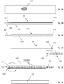
Fig. 1A shows a GUNTHER TULIP (Cook Medical, Inc.)temporary IVG filter 10 with ahook 12 end interface for retrieval. As shown inFig. 1B for aIVG filter 20, the hook may be modified or substituted for a nubbin-type interface 22. The nubbin (itself) may comprise a laser-formed or solder-formed protuberance orbump 24 on anextension 26 from ahub 28. Alternatively, as shown inFigs. 2A-2E , a/thefilter retrieval interface 22 may comprise a band 24' (e.g., a Pt marker band) mounted (e.g., by swaging, welding, gluing, etc.) on a/theextension 26. However the enlargement is created, its interaction with the rest of the system will be apparent in the following figures. - Accordingly,
Fig. 2A provides an overview of thesubject system 100. Here, a funnel-trap structure 30 made ofbraid material 32 is shown. It provides a flexible distal extension to anelongate shaft 34. The shaft is received within an elongate sleeve 50 (that may be a commercially available catheter or a custom part of the overall system 100) and may include a distalradiopaque marker band 52. - The braid may comprise Nitinol (preferably that is superelastic at body temperature), CoCr, Stainless Steel or another biocompatible material. It is advantageously braided material incorporating between 72 and 192 filament "ends" in a 1-over-1, a 2-over-2 or other pattern. With (superelastic) Nitinol, the wire is advantageously between about 0.00254cm (0.001 inches) and about 0.00762cm (0.003 inches) in diameter. In which case, a supple and relatively "smooth" matrix surface is provided from which to construct the flexible funnel-trap architecture shown and described. The value of such a surface is in its atraumatic aspect and/or ability to help guide in IVC filter interface into position for capture even if it is oriented off-angle. Still, other wire size and/or end count in a braid or other construction options are possible as well.
- To further assist with recapture, the
funnel trap structure 30 may be selectably directable. As indicated by the arrows inFigs.2A , the material from which it is made can be heatset or otherwise configured to provide a bias in an angular direction. The angle of deployment may be selectable or fully straightened by relative position of a core member or obturator (not shown) or by a sleeve or catheter sheath as further described. Further positioning may be achieved by rotating the device as further illustrated. - Other device articulation options for selecting the angular orientation of the subject funnel-trap portion of the device are possible as well. Any of a variety of steerable or directable catheter-type technologies (reliant on pull-wires or otherwise) can be incorporated in
shaft 34 for such purposes. Examples include the mechanisms described in USPNs 4,723,936; 4,960,411; 6,251,092 and 8,273,073. - In any case,
Fig. 2B shows an advantageous construction of a braided multi-filar device in cross section. Here, inner and outer braid layers 32/32' are heatset using conventional techniques (e.g., in a furnace, salt pot, etc.) in a funnel shape withdistal bends 36 in the braid wire forming anouter rim 40 with a large(r) distal opening and an meeting atinner bends 38 forming aninner rim 42 with a small(er) more proximal opening. Stated otherwise, the braid used to construct the funnel-shape trap is folded back (e.g., in a flap 46) at the distal opening to provide a more proximal opening. - This "funnel trap" may be generally frusto-conical in shape as shown or otherwise configured. With an outer conical shape (i.e., triangular shape in cross section) the structure is highly supportive for any necessary or desirable tissue discretion that might need to occur to free an emplaced filter. Moreover, such a shape provides a flexible "waist"
section 48 for the directable feature(s) noted above. Still, the device may be bowed outward along its sides or otherwise configured without departing from claimed inventive aspects or variations. - Importantly, the distal rim opening 40 is larger than the more proximal rim opening 42 to operate as illustrated in guiding filter engagement feature(s) or
enlargement 24/24' into apocket 44 where it is captured and subsequently locked upon advancingsleeve 50 as shown inFigs. 2D and 2E . - As shown, such a
pocket 44 is formed betweenbraid 32 walls and bend 38 ends optionally serving as an abutment feature with an optional shoulder 38' of nubbin/bump 24/24'. To ensure capture, thesleeve 50 may be advanced fully overtrap 30 as shown inFig. 2E before withdrawal into a separate catheter. In other words, advancingsleeve 50 overfunnel section 30 "closes the trap" and securely captures the implant to be retrieved. Otherwise, the sleeve may be a catheter andshaft 34 withdraw continue until the implant (at left) is pulled therein as well. Any or all such activity may be visualized fluoroscopically by a physician by way of marker features 24/24' and 52 and/or others as may be conveniently provided. - Notably,
system 100 may be used identically when capturing afilter 10 with a moretypical hook end 12. However, the additional bulk/lateral extension of the hook may necessitate use of a relatively larger sleeve orcatheter 50 than pictured inFigs. 2A-2E . - In the various system architectures, the catheter/pusher shaft and/or sleeve may comprise a simple extrusion (e.g., PTFE, FEP, PEEK, PI, etc.) or may be constructed using conventional catheter construction techniques and include a liner, braid support and outer jacket (not shown), metal hypotube, etc. Further, the filter frame may be constructed using conventional laser cutting and electropolishing techniques and/or be otherwise constructed. In embodiments intended for tracking through a guide/delivery catheter without an incorporated sheath, a loading sheath may be employed. Advantageously, any such loading sheath is splittable. Other typical percutaneous access instruments (such as wires, etc.), valves and other hardware may also be employed in connection with the invention embodiments.
- The funnel-
trap structure 30 may be made as a subassembly and attached to the catheter/pusher shaft.Figs. 3A-3F detail optional steps in the manufacture of a pre-form for constructing the funnel-trap portion of the final device. - In
Fig. 3A , a length orsection 200 of braid as described above is provided. Such braid is advantageously heatset under tension upon the mandrel on which it was formed. As described by now-expired USPN 6,447,531, such an approach enhances braid stability for subsequent device formation in further shape-setting of the device. - In
Fig. 3B (a cross-section view), the braid section is shown doubled over asection hypotube 300. This may be accomplished by everting what is now anouter layer 202 of thebraid 200 over the hypotube after feeding theinner layer 204 of braid there through. Alternatively, the inner layer may be fed into and through the hypotube after the outer layer is set over the hypotube. In any case, the braid wires are bent in afold 210 at a distal end of the hypotube. Next, the braid is secured to the hypotube for heatsetting (e.g., at 520°C for 5 minutes for Nitinol braid). The braid may be secured by winding or wrapping with malleable wire or external forms may be used to hold the braid relative to the hypotube for heatsetting. - After heatsetting, the hypotube is removed as shown in
Fig. 3C leaving only braid 200 inlayers Fig. 3D , the braid layers may be trimmed (e.g., with scissors) to the same length. InFig. 3D (another cross-section view), aband 302 is inserted to abut the fold in the braid. - As with
hypotube 300,band 302 preferably comprises strong material of minimal thickness. In each case, the structure is associated with forming bends in the braided wire. Thinner material will yield a tighter radius fold of the braid (or bend in the braid wires) as described. Advantageously, each ofhypotube 300 andband 302 comprise superelastic Nitinol given that in the desired wall thickness (i.e., from about 0.00254cm (0.001 inches) to about 0.00508cm (0.002 inches)) such parts are tough and less prone to deformation and/or tearing as similarly-configured (otherwise usable) stainless steel, platinum or brass pieces. - Once prepared with
band 302, the folded braid and band can be received within a pocket orsocket 312 of arod 310 or an end of another tube or hypotube. The pocket may offer a light press fit to the braid. Otherwise, the band-and-braid intermediate construction may be secured insocket 310 with glue (e.g., LOCTITE 4014). - Then, both layers of
braid 202/204 are flipped or everted over the rod and secured thereto (e.g., as by wrapping per above) as shown inFig. 3E . So-fixtured,braid 200 includes asecond fold 212 as shown in (cross-section view)Fig. 3E . Upon heatsetting (e.g., again, as per above), the fold(s) are set or fixed in shape. Then, the rod and band are removed providing afinished preform 220 as shown inFig. 3F . - Such an approach to forming the
bends 210/212 is advantageous in view of its simplified tooling. Further, the tooling used (i.e., bands and/or tubes) for this approach can be minimized in thickness to provide the tightest folds possible in the braid. As such, minimum diameter can be achieved for the compressed medical device as ultimately formed. - Regarding such formation (i.e., conversion from preform to final device configuration),
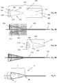
Fig. 4A illustrates a first set oftooling 320 that may be so-used.Toolset 320 includes an internal form ormandrel 330 and anexternal form 340 withcavity 342. These are shown in use relative to preform 220 in (cross-section view)Fig. 4B . With the braid so-positioned and secured over a rod 322 (e.g., tied-down as per above), optionally in connection with asetscrew 324, the braid is heated within the tooling construct to define a final funnel-trap device shape (e.g., as elaborated upon in connection withFig. 6 ). - Notably, this final heatsetting cycle may take longer than previous cycles due to the thermal mass of the tooling. As such, it may be desirable to heat treat for approximately 10 minutes at temperature. Furthermore, it may be desirable to heatset in an inert atmosphere to minimize oxide formation. The same holds true for preceding heatsetting activities.
- As for specific tooling features,
mandrel 330 includescone sections 332/332' andshoulder sections 334/334'. Together, these sections provide guidance for final device angular configuration and formation. Arod clearance hold 336 and a threadedsetscrew hole 338 may also be provided inmandrel 330.External form 340 includes theaforementioned pocket 342 as well as optional setscrew androd clearance holes -
External form 340 need not be used in shape-setting. However, its use/inclusion in the forming process may advantageously reduce part-to-part variability by further constraint in its application. -
Fig. 5A illustrates a second tooling approach for converting thepreform 220 to a finally shaped device. Here, a two-part mandrel 350 is provided. It includes acone piece 360 with an angled inset orpocket 362 that offers potential advantages by constraining the flap and fold 212 of the braid at rim orlip 364. Anabutment piece 370 oftool 350 may be used to further constrain the braid. It includes acone section 372 complementary toinset 362 and may also include ashoulder section 374 to further constrain or compress the braid during heatsetting. Together (or usingcone piece 360, alone) the additional constraint in the fold and flap region -- as compared to the configuration offered withmandrel 330 -- may obviate the need or advantage of using an external form likeform 340 in the forming process such as shown in (cross-section view)Fig. 5B . Still, an external form (likeform 340 shown inFig.4A ) may be used in connection withtooling 350. - In general, the aforementioned forming methods are ones in which a heatset (possibly multiple-staged heatset) preform is provided that is substantially cylindrical in shape and includes an interior folded "flap" section. As such, the preform resembles the subject device in its fully compressed state for catheter tracking. Then, the preform is expanded (e.g., in a conical shape) to a desired "working" configuration and heatset accordingly.
- Another forming and tooling approach may use thin-wall conical bands (not shown) in the shape-setting procedure. These may be used to directly shape or form the cone and flap sections of
trap device 30. Such tooling may be constructed by "spinning" down thin-walled cylindrical material to the desired conical shapes and then trimming final pieces to length. However, use of internal tooling (as such) may limit the extent to which the braid layers lay in apposition after heatsetting, thereby resulting is some gap between the layers (i.e., unless the braid is subsequently formed with tooling as shown inFigs. 4A/5A or otherwise). - Regardless of which tooling approach is employed,
Fig. 6 illustrates a preform after conversion (or braid otherwise formed) to the subject funnel-trap architecture 30. For IVC filter retrieval, the funnel-trap portion 30 may have a diameter (D) from about 5 mm to about 20 mm, or more preferably about 10 to about 15 mm (i.e., size in a range to work within average size human IVCs where such vessels are reported as having a mean diameter of 20 mm within a range of 13 to 30 mm). A length (L) may range from about 10 mm to about 30 mm. An overall cone angle (α) may be between about 30 and about 90 degrees. An angle (β) offlap 46 may be between about 0 and about 60 degrees and flap length (F) may be between about 1 and about 10 rnm in length. Overall, a funnel trap opening diameter (d) may be between about 5 and about 95 percent of diameter (D) depending on the selected combination of the noted variables (i.e., d, D, L, F, a and ∼). At the lower end of this range, the inner "opening" may be substantially closed such that is must be pushed-open to receive the proximal engagement feature(s) of the implant during retrieval. At the higher end of the range, the flap may lie completely along or in-line with the outer layer(s) of the device. - Variations
- The subject methods, including methods of use and/or manufacture, may be carried out in any order of the events which is logically possible, as well as any recited order of events. Medical methods may include any of a hospital staff's activities associated with device provision, implant positioning, re-positioning, retrieval and/or release.
- Furthermore, where a range of values is provided, it is understood that every intervening value, between the upper and lower limit of that range and any other stated or intervening value in the stated range is encompassed within the invention. Also, it is contemplated that any optional feature of the inventive variations described may be set forth and claimed independently, or in combination with any one or more of the features described herein.
- Though the invention has been described in reference to several examples, optionally incorporating various features, the invention is not to be limited to that which is described or indicated as contemplated with respect to each variation of the invention. Various changes may be made to the invention described and equivalents (whether recited herein or not included for the sake of some brevity) may be substituted without departing from the scope of the invention as long as covered by the language of the appended claims.
- Reference to a singular item includes the possibility that there are a plurality of the same items present. In other words, use of the articles allow for "at least one" of the subject item in the description above as well as the claims below. It is further noted that the claims may be drafted to exclude any optional element.
- Without the use of such exclusive terminology, the term "comprising" in the claims shall allow for the inclusion of any additional element--irrespective of whether a given number of elements are enumerated in the claim, or the addition of a feature could be regarded as transforming the nature of an element set forth in the claims. Except as specifically defined herein, all technical and scientific terms used herein are to be given as broad a commonly understood meaning as possible while maintaining claim validity. Accordingly, the different inventive embodiments or aspects described herein is not to be limited to the examples provided and/or the subject specification, but rather only by the scope of the issued claim language.
Claims (14)
- An apparatus (100) for an inferior vena cava filter (10) delivery or retrieval, the apparatus comprising:an elongate sleeve (50) or catheter, andan elongate shaft (34) received within the sleeve, the shaft having a flexible distal extension (30) comprising a braid (32, 200) folded back into two braid layers (32, 32', 202, 204) at a first fold (38, 210), the two layers folded-back inwardly at a second fold (36, 212) and heatset such that the first fold (38, 210) forms a proximal opening (42) of a funnel and the second fold (36, 212) forms a distal opening (40) of the funnel, the distal opening (40) being larger than the proximal opening (42);wherein the proximal opening (42) is sized to receive and pass an enlarged end of the inferior vena cava filter (10) there through and the apparatus is adapted such that the enlarged end of the inferior vena cava filter (10) is securable within a pocket (44) in the funnel and the inferior vena cava filter (10) is retrievable from the vasculature with the apparatus by advancing the sleeve or a catheter over the distal extension.
- The apparatus (100) of claim 1, wherein the distal extension comprises Nitinol braid (32, 200) with between 72 and 192 end count and optionally wherein the shaft (34) includes the Nitinol braid.
- The apparatus (100) of claim 1, wherein the distal extension (30) is selectable in angular orientation.
- The apparatus (100) of claim 1, wherein the apparatus is adapted to secure the enlarged end when the enlarged end is a band (24') or a hook (12).
- A method of making an apparatus for an inferior vena cava filter (10) delivery or retrieval, the method comprising:forming a section of tubular braid (32, 200) with a first fold (38, 210); andforming the braid with a second fold (36, 212);wherein a funnel-shape trap is formed between the first and second fold and heatset, the funnel-shape trap having a distal rim opening (40) that is larger than a proximal rim opening (42);wherein the tubular braid (32, 200) is formed as an extension to an elongate shaft (34), and the method further comprises placing the elongate shaft (34) within a sleeve (50) or catheter.
- The method of claim 5, further comprising heatsetting the braid (32, 200) after the first fold (38, 210) is formed.
- The method of claim 5, further comprising heatsetting the braid (32, 200) after the second fold (36, 212) is formed.
- The method of claim 5, wherein the braid (32, 200) is configured in a generally cylindrical shape when forming the folds (36, 38, 210, 212).
- The method of claim 6, further comprising heatsetting the braid (32, 200) in the generally cylindrical shape.
- The method of claim 7, further comprising expanding the braid (32, 200) into a generally conical shape and optionally, wherein the method further comprises holding the funnel-shape trap at an angle relatively more flat relative to an angle of the cone.
- The method of claim 10, further comprising heatsetting the braid (32, 200) in the generally conical shape.
- The method of claim 5, wherein the first and second folds (36, 38, 210, 212) are formed in a compressed condition.
- The method of claim 5, further comprising:inserting a band (302) adjacent the first fold (38, 210);inserting the band with the braid into a socket (312); andforming the second fold (36, 212) at an edge of the socket.
- The apparatus (100) of claim 1, wherein the distal extension has an exterior conical shape.
Priority Applications (1)
| Application Number | Priority Date | Filing Date | Title |
|---|---|---|---|
| EP19208256.8A EP3666227A1 (en) | 2013-06-14 | 2014-06-13 | Inferior vena cava filter and retrieval systems |
Applications Claiming Priority (2)
| Application Number | Priority Date | Filing Date | Title |
|---|---|---|---|
| US201361835295P | 2013-06-14 | 2013-06-14 | |
| PCT/US2014/042343 WO2014201380A1 (en) | 2013-06-14 | 2014-06-13 | Inferior vena cava filter and retrieval systems |
Related Child Applications (1)
| Application Number | Title | Priority Date | Filing Date |
|---|---|---|---|
| EP19208256.8A Division EP3666227A1 (en) | 2013-06-14 | 2014-06-13 | Inferior vena cava filter and retrieval systems |
Publications (3)
| Publication Number | Publication Date |
|---|---|
| EP3007648A1 EP3007648A1 (en) | 2016-04-20 |
| EP3007648A4 EP3007648A4 (en) | 2016-12-28 |
| EP3007648B1 true EP3007648B1 (en) | 2019-11-13 |
Family
ID=52022808
Family Applications (2)
| Application Number | Title | Priority Date | Filing Date |
|---|---|---|---|
| EP14810754.3A Active EP3007648B1 (en) | 2013-06-14 | 2014-06-13 | Inferior vena cava filter and retrieval systems |
| EP19208256.8A Pending EP3666227A1 (en) | 2013-06-14 | 2014-06-13 | Inferior vena cava filter and retrieval systems |
Family Applications After (1)
| Application Number | Title | Priority Date | Filing Date |
|---|---|---|---|
| EP19208256.8A Pending EP3666227A1 (en) | 2013-06-14 | 2014-06-13 | Inferior vena cava filter and retrieval systems |
Country Status (7)
| Country | Link |
|---|---|
| US (5) | US10022213B2 (en) |
| EP (2) | EP3007648B1 (en) |
| JP (2) | JP2016523631A (en) |
| CN (1) | CN105578989B (en) |
| AU (1) | AU2014277922B2 (en) |
| CA (1) | CA2913773C (en) |
| WO (1) | WO2014201380A1 (en) |
Cited By (1)
| Publication number | Priority date | Publication date | Assignee | Title |
|---|---|---|---|---|
| US11690651B2 (en) | 2015-09-04 | 2023-07-04 | The Trustees Of The University Of Pennsylvania | Systems and methods for percutaneous removal of objects from an internal body space |
Families Citing this family (30)
| Publication number | Priority date | Publication date | Assignee | Title |
|---|---|---|---|---|
| AU2014277922B2 (en) | 2013-06-14 | 2019-01-31 | Avantec Vascular Corporation | Inferior Vena Cava filter and retrieval systems |
| WO2016073530A1 (en) | 2014-11-04 | 2016-05-12 | Avantec Vascular Corporation | Catheter device with longitudinally expanding interior components for compressing cancellous bone |
| EP3229729B1 (en) * | 2014-12-12 | 2023-03-15 | Avantec Vascular Corporation | Ivc filter retrieval systems with interposed support members |
| US10278804B2 (en) | 2014-12-12 | 2019-05-07 | Avantec Vascular Corporation | IVC filter retrieval systems with releasable capture feature |
| US10238791B2 (en) * | 2015-01-05 | 2019-03-26 | Boston Scientific Scimed, Inc. | Flexible member for resisting retrograde flow |
| EP3288493B1 (en) * | 2015-04-29 | 2022-11-30 | Micro Medical Solutions, Inc. | Stent delivery system |
| JP6873998B2 (en) * | 2015-12-10 | 2021-05-19 | アバンテック バスキュラー コーポレイション | Improved sheath of IVC filter recovery system |
| JP6757410B2 (en) * | 2015-12-10 | 2020-09-16 | アバンテック バスキュラー コーポレイション | IVC filter recovery system with multiple capture modes |
| GB201615219D0 (en) | 2016-09-07 | 2016-10-19 | Vascutek Ltd And Univ Medical Center Hamburg-Eppendorf (Uke) | Hybrid prosthesis and delivery system |
| GB2554670B (en) * | 2016-09-30 | 2022-01-05 | Vascutek Ltd | A vascular graft |
| EP3558161A4 (en) * | 2016-12-22 | 2020-08-12 | Avantec Vascular Corporation | Systems, devices, and methods for retrieval systems having a tether |
| WO2018156849A1 (en) | 2017-02-24 | 2018-08-30 | Bolton Medical, Inc. | Vascular prosthesis with fenestration ring and methods of use |
| WO2018156847A1 (en) | 2017-02-24 | 2018-08-30 | Bolton Medical, Inc. | Delivery system and method to radially constrict a stent graft |
| WO2018156851A1 (en) | 2017-02-24 | 2018-08-30 | Bolton Medical, Inc. | Vascular prosthesis with moveable fenestration |
| CN109843226B (en) | 2017-02-24 | 2022-05-17 | 波顿医疗公司 | Delivery systems and methods of use for radially contracting stent grafts |
| ES2863978T3 (en) | 2017-02-24 | 2021-10-13 | Bolton Medical Inc | System for radially constricting a stent graft |
| ES2859485T3 (en) | 2017-02-24 | 2021-10-04 | Bolton Medical Inc | Radially Adjustable Stent Graft Delivery System |
| CN110022795B (en) | 2017-02-24 | 2023-03-14 | 波顿医疗公司 | Constrained stent grafts, delivery systems and methods of use |
| WO2018156850A1 (en) | 2017-02-24 | 2018-08-30 | Bolton Medical, Inc. | Stent graft with fenestration lock |
| WO2018156848A1 (en) | 2017-02-24 | 2018-08-30 | Bolton Medical, Inc. | Vascular prosthesis with crimped adapter and methods of use |
| CN109890331B (en) | 2017-02-24 | 2022-07-12 | 波顿医疗公司 | Stent-graft delivery system with a shrink sheath and method of use |
| US10792151B2 (en) * | 2017-05-11 | 2020-10-06 | Twelve, Inc. | Delivery systems for delivering prosthetic heart valve devices and associated methods |
| GB201707929D0 (en) | 2017-05-17 | 2017-06-28 | Vascutek Ltd | Tubular medical device |
| US10238466B2 (en) * | 2017-06-15 | 2019-03-26 | Cook Medical Technologies Llc | Method of making a superelastic medical device with a radiopaque marker |
| GB201715658D0 (en) | 2017-09-27 | 2017-11-08 | Vascutek Ltd | An endoluminal device |
| ES2910187T3 (en) | 2017-10-31 | 2022-05-11 | Bolton Medical Inc | Distal torque component, delivery system and method of use thereof |
| CN112584799A (en) | 2018-06-29 | 2021-03-30 | 阿万泰血管公司 | Systems and methods for implants and deployment devices |
| CN109998611B (en) * | 2019-04-02 | 2024-02-27 | 北京大学口腔医学院 | Hollow vector support multifunctional protection device for minimally invasive surgery |
| JP7201542B2 (en) | 2019-06-21 | 2023-01-10 | ミネベアミツミ株式会社 | Rolling bearing, rotating device, bearing monitoring device, bearing monitoring method |
| JP2020189223A (en) * | 2020-08-28 | 2020-11-26 | アバンテック バスキュラー コーポレイション | Ivc filter retrieval systems with multiple capture modes |
Family Cites Families (174)
| Publication number | Priority date | Publication date | Assignee | Title |
|---|---|---|---|---|
| US3952747A (en) | 1974-03-28 | 1976-04-27 | Kimmell Jr Garman O | Filter and filter insertion instrument |
| US3952737A (en) | 1974-08-28 | 1976-04-27 | The Medevice Company | Contraceptive |
| US4085743A (en) | 1976-03-02 | 1978-04-25 | In Bae Yoon | Multiple occlusion ring applicator and method |
| US4174715A (en) | 1977-03-28 | 1979-11-20 | Hasson Harrith M | Multi-pronged laparoscopy forceps |
| DE3012447C2 (en) | 1980-03-31 | 1982-04-01 | Harald 7200 Tuttlingen Maslanka | Surgical grasper instrument |
| US4655219A (en) | 1983-07-22 | 1987-04-07 | American Hospital Supply Corporation | Multicomponent flexible grasping device |
| US4611594A (en) | 1984-04-11 | 1986-09-16 | Northwestern University | Medical instrument for containment and removal of calculi |
| US4960411A (en) | 1984-09-18 | 1990-10-02 | Medtronic Versaflex, Inc. | Low profile sterrable soft-tip catheter |
| US4723936A (en) | 1986-07-22 | 1988-02-09 | Versaflex Delivery Systems Inc. | Steerable catheter |
| US4873978A (en) * | 1987-12-04 | 1989-10-17 | Robert Ginsburg | Device and method for emboli retrieval |
| US5011488A (en) | 1988-12-07 | 1991-04-30 | Robert Ginsburg | Thrombus extraction system |
| US5074845A (en) | 1989-07-18 | 1991-12-24 | Baxter International Inc. | Catheter with heat-fused balloon with waist |
| DE8910603U1 (en) | 1989-09-06 | 1989-12-07 | Guenther, Rolf W., Prof. Dr. | |
| US5041093A (en) | 1990-01-31 | 1991-08-20 | Boston Scientific Corp. | Catheter with foraminous anchor |
| US5098440A (en) | 1990-08-14 | 1992-03-24 | Cordis Corporation | Object retrieval method and apparatus |
| US5370647A (en) | 1991-01-23 | 1994-12-06 | Surgical Innovations, Inc. | Tissue and organ extractor |
| DE69328096T2 (en) | 1992-06-26 | 2000-09-14 | Schneider Usa Inc | CATHETER WITH EXTENDABLE MACHINE WIRE TIP |
| US6123715A (en) * | 1994-07-08 | 2000-09-26 | Amplatz; Curtis | Method of forming medical devices; intravascular occlusion devices |
| EP1695673A3 (en) | 1994-07-08 | 2009-07-08 | ev3 Inc. | Intravascular filtering device |
| US5601595A (en) | 1994-10-25 | 1997-02-11 | Scimed Life Systems, Inc. | Remobable thrombus filter |
| US5709704A (en) | 1994-11-30 | 1998-01-20 | Boston Scientific Corporation | Blood clot filtering |
| US5549626A (en) | 1994-12-23 | 1996-08-27 | New York Society For The Ruptured And Crippled Maintaining The Hospital For Special Surgery | Vena caval filter |
| BE1009746A3 (en) | 1995-11-07 | 1997-07-01 | Dereume Jean Pierre Georges Em | Capture device introduced in a cavity of a human or animal body. |
| US5846251A (en) * | 1996-07-22 | 1998-12-08 | Hart; Charles C. | Access device with expandable containment member |
| US5782747A (en) | 1996-04-22 | 1998-07-21 | Zimmon Science Corporation | Spring based multi-purpose medical instrument |
| US6800080B1 (en) | 1996-05-03 | 2004-10-05 | Scimed Life Systems, Inc. | Medical retrieval device |
| US5746251A (en) | 1996-05-23 | 1998-05-05 | Bullard; Horace | Multi-port fluid valve |
| US5662671A (en) | 1996-07-17 | 1997-09-02 | Embol-X, Inc. | Atherectomy device having trapping and excising means for removal of plaque from the aorta and other arteries |
| US6395017B1 (en) | 1996-11-15 | 2002-05-28 | C. R. Bard, Inc. | Endoprosthesis delivery catheter with sequential stage control |
| US6210370B1 (en) | 1997-01-10 | 2001-04-03 | Applied Medical Resources Corporation | Access device with expandable containment member |
| US5800457A (en) | 1997-03-05 | 1998-09-01 | Gelbfish; Gary A. | Intravascular filter and associated methodology |
| US5814064A (en) | 1997-03-06 | 1998-09-29 | Scimed Life Systems, Inc. | Distal protection device |
| US5827324A (en) | 1997-03-06 | 1998-10-27 | Scimed Life Systems, Inc. | Distal protection device |
| US6152946A (en) | 1998-03-05 | 2000-11-28 | Scimed Life Systems, Inc. | Distal protection device and method |
| US5911734A (en) | 1997-05-08 | 1999-06-15 | Embol-X, Inc. | Percutaneous catheter and guidewire having filter and medical device deployment capabilities |
| US5928260A (en) | 1997-07-10 | 1999-07-27 | Scimed Life Systems, Inc. | Removable occlusion system for aneurysm neck |
| US5908435A (en) | 1997-10-23 | 1999-06-01 | Samuels; Shaun L. W. | Expandable lumen device and method of use |
| EP1028670B1 (en) | 1997-11-07 | 2008-01-02 | Salviac Limited | An embolic protection device |
| US20040199202A1 (en) | 1997-11-12 | 2004-10-07 | Genesis Technologies Llc | Biological passageway occlusion removal |
| EP1030603B1 (en) * | 1997-11-12 | 2008-08-13 | Genesis Technologies LLC. | Biological passageway occlusion removal |
| US6443972B1 (en) | 1997-11-19 | 2002-09-03 | Cordis Europa N.V. | Vascular filter |
| US6251092B1 (en) | 1997-12-30 | 2001-06-26 | Medtronic, Inc. | Deflectable guiding catheter |
| JP2002502626A (en) | 1998-02-10 | 2002-01-29 | アーテミス・メディカル・インコーポレイテッド | Supplementary device and method of using the same |
| DE69931152T2 (en) | 1998-03-27 | 2007-04-05 | Cook Urological Inc., Spencer | MINIMALLY INVASIVE APPARATUS FOR COLLECTING OBJECTS IN HOLLOWERS |
| US5944728A (en) | 1998-04-23 | 1999-08-31 | Boston Scientific Corporation | Surgical retrieval basket with the ability to capture and release material |
| US6645222B1 (en) | 1998-05-13 | 2003-11-11 | Arteria Medical Science, Inc. | Puncture resistant branch artery occlusion device and methods of use |
| US6306163B1 (en) | 1998-08-04 | 2001-10-23 | Advanced Cardiovascular Systems, Inc. | Assembly for collecting emboli and method of use |
| US6342062B1 (en) * | 1998-09-24 | 2002-01-29 | Scimed Life Systems, Inc. | Retrieval devices for vena cava filter |
| US6331183B1 (en) | 1998-09-24 | 2001-12-18 | Scimed Life Systems, Inc. | Basket filter |
| US6896690B1 (en) | 2000-01-27 | 2005-05-24 | Viacor, Inc. | Cardiac valve procedure methods and devices |
| DE60042316D1 (en) | 1999-01-28 | 2009-07-16 | Salviac Ltd | CATHETER WITH EXPANDABLE END CUT |
| US20020169474A1 (en) | 1999-03-08 | 2002-11-14 | Microvena Corporation | Minimally invasive medical device deployment and retrieval system |
| US6632236B2 (en) | 1999-03-12 | 2003-10-14 | Arteria Medical Science, Inc. | Catheter having radially expandable main body |
| US6156055A (en) * | 1999-03-23 | 2000-12-05 | Nitinol Medical Technologies Inc. | Gripping device for implanting, repositioning or extracting an object within a body vessel |
| US6743247B1 (en) | 1999-04-01 | 2004-06-01 | Scion Cardio-Vascular, Inc. | Locking frame, filter and deployment system |
| US6287335B1 (en) | 1999-04-26 | 2001-09-11 | William J. Drasler | Intravascular folded tubular endoprosthesis |
| FR2794653B1 (en) | 1999-06-14 | 2001-12-21 | Sarl Aln | KIT FOR THE REMOVAL OF A BLADDER VESSEL FILTER OF THE UMBRELLA TYPE |
| US6203561B1 (en) | 1999-07-30 | 2001-03-20 | Incept Llc | Integrated vascular device having thrombectomy element and vascular filter and methods of use |
| US6251122B1 (en) | 1999-09-02 | 2001-06-26 | Scimed Life Systems, Inc. | Intravascular filter retrieval device and method |
| US6458151B1 (en) | 1999-09-10 | 2002-10-01 | Frank S. Saltiel | Ostial stent positioning device and method |
| US6264671B1 (en) | 1999-11-15 | 2001-07-24 | Advanced Cardiovascular Systems, Inc. | Stent delivery catheter and method of use |
| US6660021B1 (en) | 1999-12-23 | 2003-12-09 | Advanced Cardiovascular Systems, Inc. | Intravascular device and system |
| US6290710B1 (en) | 1999-12-29 | 2001-09-18 | Advanced Cardiovascular Systems, Inc. | Embolic protection device |
| US6702834B1 (en) | 1999-12-30 | 2004-03-09 | Advanced Cardiovascular Systems, Inc. | Embolic protection devices |
| US6695813B1 (en) | 1999-12-30 | 2004-02-24 | Advanced Cardiovascular Systems, Inc. | Embolic protection devices |
| GB2369575A (en) | 2000-04-20 | 2002-06-05 | Salviac Ltd | An embolic protection system |
| AU2001259429A1 (en) | 2000-05-02 | 2001-11-12 | Wilson-Cook Medical Inc. | Introducer device for catheters o.t.l. with eversible sleeve |
| US6602271B2 (en) | 2000-05-24 | 2003-08-05 | Medtronic Ave, Inc. | Collapsible blood filter with optimal braid geometry |
| EP1172073A1 (en) | 2000-07-13 | 2002-01-16 | Cordis Corporation | Vascular filter system with guidewire and capture mechanism |
| US6485501B1 (en) * | 2000-08-11 | 2002-11-26 | Cordis Corporation | Vascular filter system with guidewire and capture mechanism |
| US6679893B1 (en) | 2000-11-16 | 2004-01-20 | Chestnut Medical Technologies, Inc. | Grasping device and method of use |
| US6569181B1 (en) | 2000-12-20 | 2003-05-27 | Advanced Cardiovascular Systems, Inc. | Stent retrieval system |
| US6569184B2 (en) | 2001-02-27 | 2003-05-27 | Advanced Cardiovascular Systems, Inc. | Recovery system for retrieving an embolic protection device |
| US6783538B2 (en) | 2001-06-18 | 2004-08-31 | Rex Medical, L.P | Removable vein filter |
| US7780693B2 (en) | 2001-06-27 | 2010-08-24 | Salviac Limited | Catheter |
| US6958074B2 (en) * | 2002-01-07 | 2005-10-25 | Cordis Corporation | Releasable and retrievable vascular filter system |
| EP1482861B1 (en) | 2002-03-05 | 2007-08-08 | Salviac Limited | An embolic protection system |
| US20030176884A1 (en) | 2002-03-12 | 2003-09-18 | Marwane Berrada | Everted filter device |
| US6881218B2 (en) | 2002-05-01 | 2005-04-19 | Angiodynamics, Inc. | Blood clot filter |
| US20040093012A1 (en) | 2002-10-17 | 2004-05-13 | Cully Edward H. | Embolic filter frame having looped support strut elements |
| US7211089B2 (en) | 2002-10-18 | 2007-05-01 | Scimed Life Systems, Inc. | Medical retrieval device |
| AU2003285248A1 (en) * | 2002-11-29 | 2004-06-23 | Vascular Interventional Technologies Inc. | Embolus blood clot filter |
| US7678119B2 (en) | 2003-01-15 | 2010-03-16 | Scimed Life Systems, Inc. | Medical retrieval device with frangible basket |
| US7220271B2 (en) | 2003-01-30 | 2007-05-22 | Ev3 Inc. | Embolic filters having multiple layers and controlled pore size |
| US7658747B2 (en) | 2003-03-12 | 2010-02-09 | Nmt Medical, Inc. | Medical device for manipulation of a medical implant |
| US7322989B2 (en) | 2003-04-24 | 2008-01-29 | Boston Scientific Scimed, Inc. | Retractable grasper |
| GB2400038A (en) | 2003-06-20 | 2004-10-06 | Ranier Ltd | Drainage catheter |
| US7377925B2 (en) | 2003-09-16 | 2008-05-27 | Minimally Invasive Devices, Llc | Fragmentation and extraction basket |
| US7591813B2 (en) | 2003-10-01 | 2009-09-22 | Micrus Endovascular Corporation | Long nose manipulatable catheter |
| US7344550B2 (en) | 2003-10-21 | 2008-03-18 | Boston Scientific Scimed, Inc. | Clot removal device |
| US20050159770A1 (en) | 2004-01-21 | 2005-07-21 | Diqur Medical Systems, Llc | Funnel catheter device and method of operation thereof |
| US7338512B2 (en) | 2004-01-22 | 2008-03-04 | Rex Medical, L.P. | Vein filter |
| US7323003B2 (en) * | 2004-02-13 | 2008-01-29 | Boston Scientific Scimed, Inc. | Centering intravascular filters and devices and methods for deploying and retrieving intravascular filters |
| WO2005079678A1 (en) | 2004-02-19 | 2005-09-01 | Applied Medical Resources Corporation | Embolectomy capture sheath |
| US7625390B2 (en) | 2004-04-16 | 2009-12-01 | Cook Incorporated | Removable vena cava filter |
| AU2005234753B2 (en) | 2004-04-16 | 2010-12-02 | Cook, Inc. | Removable vena cava filter having inwardly positioned anchoring hooks in collapsed configuration |
| US7799050B2 (en) | 2004-05-05 | 2010-09-21 | Boston Scientific Scimed, Inc. | Devices and methods for magnetically manipulating intravascular devices |
| US20050283166A1 (en) | 2004-06-17 | 2005-12-22 | Secant Medical, Llc | Expandible snare |
| US7367975B2 (en) | 2004-06-21 | 2008-05-06 | Cierra, Inc. | Energy based devices and methods for treatment of anatomic tissue defects |
| US7850675B2 (en) * | 2004-07-20 | 2010-12-14 | Boston Scientific Scimed, Inc. | Reinforced venous access catheter |
| ATE520369T1 (en) | 2004-09-17 | 2011-09-15 | Nitinol Dev Corp | SHAPE MEMORY THIN FILM EMBOLIC PROTECTION DEVICE |
| US7749246B2 (en) | 2004-09-27 | 2010-07-06 | Rex Medical, L.P. | Vein filter |
| US7993362B2 (en) * | 2005-02-16 | 2011-08-09 | Boston Scientific Scimed, Inc. | Filter with positioning and retrieval devices and methods |
| US8603122B2 (en) | 2005-04-01 | 2013-12-10 | Nexgen Medical Systems, Incorporated | Thrombus removal system and process |
| EP1871285A1 (en) | 2005-04-18 | 2008-01-02 | Salviac Limited | A filter catheter |
| US8025668B2 (en) * | 2005-04-28 | 2011-09-27 | C. R. Bard, Inc. | Medical device removal system |
| AU2006242378B2 (en) | 2005-05-04 | 2011-07-07 | Cook Medical Technologies Llc | Expandable and retrievable stent |
| FR2885794B1 (en) | 2005-05-19 | 2007-08-17 | Perouse Soc Par Actions Simpli | NECESSARY FOR LANDING A CAVITY TREATMENT BODY AND METHOD FOR PREPARING A TREATMENT BODY THEREFOR |
| US8038704B2 (en) | 2005-07-27 | 2011-10-18 | Paul S. Sherburne | Stent and other objects removal from a body |
| US8252017B2 (en) | 2005-10-18 | 2012-08-28 | Cook Medical Technologies Llc | Invertible filter for embolic protection |
| DE102005052628B4 (en) | 2005-11-04 | 2014-06-05 | Jenavalve Technology Inc. | Self-expanding, flexible wire mesh with integrated valvular prosthesis for the transvascular heart valve replacement and a system with such a device and a delivery catheter |
| JP2009517124A (en) | 2005-11-26 | 2009-04-30 | コンテゴ メディカル エルエルシー | Percutaneous transluminal angioplasty device with integrated embolic filter |
| US9034006B2 (en) | 2005-12-01 | 2015-05-19 | Atritech, Inc. | Method and apparatus for retrieving an embolized implant |
| US8052715B2 (en) | 2005-12-01 | 2011-11-08 | Atritech, Inc. | Method and apparatus for recapturing an implant from the left atrial appendage |
| JP2009519049A (en) * | 2005-12-02 | 2009-05-14 | シー・アール・バード・インコーポレイテツド | Spiral vena cava filter |
| US7837702B2 (en) | 2005-12-21 | 2010-11-23 | Nexeon Medsystems, Inc. | Interventional catheter for retrograde use having embolic protection capability and methods of use |
| US20070149996A1 (en) | 2005-12-28 | 2007-06-28 | Medtronic Vascular, Inc. | Low profile filter |
| CA2633866A1 (en) | 2005-12-30 | 2007-07-12 | C.R. Bard Inc. | Embolus blood clot filter removal system and method |
| US20070186933A1 (en) | 2006-01-17 | 2007-08-16 | Pulmonx | Systems and methods for delivering flow restrictive element to airway in lungs |
| AU2007205867A1 (en) | 2006-01-20 | 2007-07-26 | Angiodynamics, Inc. | Retrievable blood clot filter |
| WO2007110864A2 (en) | 2006-03-27 | 2007-10-04 | Tel Hashomer Medical Research Infrastructure And Services Ltd. | Intraluminal mass collector |
| US20070239254A1 (en) | 2006-04-07 | 2007-10-11 | Chris Chia | System for percutaneous delivery and removal of a prosthetic valve |
| EP1849440A1 (en) * | 2006-04-28 | 2007-10-31 | Younes Boudjemline | Vascular stents with varying diameter |
| GB0700560D0 (en) | 2007-01-11 | 2007-02-21 | Emcision Ltd | Device and method for the treatment of diseased tissue such as tumours |
| CA2655158A1 (en) | 2006-06-05 | 2007-12-13 | C.R. Bard Inc. | Embolus blood clot filter utilizable with a single delivery system or a single retrieval system in one of a femoral or jugular access |
| US20080269774A1 (en) | 2006-10-26 | 2008-10-30 | Chestnut Medical Technologies, Inc. | Intracorporeal Grasping Device |
| WO2008066881A1 (en) | 2006-11-29 | 2008-06-05 | Amir Belson | Embolic protection device |
| US8486138B2 (en) | 2007-08-21 | 2013-07-16 | Valvexchange Inc. | Method and apparatus for prosthetic valve removal |
| WO2009086482A1 (en) * | 2007-12-26 | 2009-07-09 | Lazarus Effect, Inc. | Retrieval systems and methods for use thereof |
| US20090192485A1 (en) | 2008-01-28 | 2009-07-30 | Heuser Richard R | Snare device |
| US8163004B2 (en) | 2008-02-18 | 2012-04-24 | Aga Medical Corporation | Stent graft for reinforcement of vascular abnormalities and associated method |
| US8246649B2 (en) | 2008-03-19 | 2012-08-21 | Schneider M Bret | Electrostatic vascular filters |
| WO2009146128A1 (en) | 2008-04-03 | 2009-12-03 | William Cook Europe Aps | Implant release mechanism |
| WO2009132045A2 (en) * | 2008-04-21 | 2009-10-29 | Nfocus Neuromedical, Inc. | Braid-ball embolic devices and delivery systems |
| US9192362B2 (en) | 2008-08-18 | 2015-11-24 | Cook Medical Technologies Llc | Device and method for closure of vessel access site |
| US8034095B2 (en) | 2008-08-29 | 2011-10-11 | Cook Medical Technologies Llc | Intraluminal system for retrieving an implantable medical device |
| EP2355717B1 (en) | 2008-12-01 | 2014-02-19 | Percutaneous Systems, Inc. | Systems for capturing and removing urinary stones from body cavities |
| FR2945206B1 (en) * | 2009-05-06 | 2011-06-17 | Aln | EXTRACTION KIT FOR FILTER FOR CELLAR VEIN |
| DK2442860T3 (en) | 2009-06-15 | 2019-06-24 | Perflow Medical Ltd | APPARATUS FOR POSSIBLE BLOOD FLOWING THROUGH AN UNCLUDED CAR |
| US20110040321A1 (en) | 2009-08-11 | 2011-02-17 | Angiodynamics, Inc. | Retrieval Device and Method of Use |
| KR101133157B1 (en) | 2009-10-13 | 2012-04-06 | 연세대학교 산학협력단 | Detachable and retrievable embolic protection device and filter assembly composing the same |
| US8409240B2 (en) | 2009-11-25 | 2013-04-02 | Boston Scientific Scimed, Inc. | Embolic protection device |
| WO2011091383A1 (en) | 2010-01-22 | 2011-07-28 | Lazarus Effect, Inc. | Retrieval systems and methods for use thereof |
| US20120316638A1 (en) | 2010-02-08 | 2012-12-13 | Surpass Medical Ltd. | Method and device for treating cerebrovascular pathologies and delivery system therefor |
| CA2793561A1 (en) | 2010-03-06 | 2011-09-15 | Nfusion Vascular Systems, Llc | Recovery catheter assembly |
| US8512401B2 (en) | 2010-04-12 | 2013-08-20 | Medtronic, Inc. | Transcatheter prosthetic heart valve delivery system with funnel recapturing feature and method |
| CN102970938A (en) | 2010-04-13 | 2013-03-13 | 访问点技术公司 | Embolic material excision trapping device |
| DE102010045367B4 (en) | 2010-05-18 | 2019-08-08 | Acandis Gmbh | Medical device for removing concrements |
| CN103079497B (en) | 2010-06-30 | 2016-08-03 | 玛芬股份有限公司 | The percutaneous ultrasound of armarium guides and imports |
| WO2012009675A2 (en) | 2010-07-15 | 2012-01-19 | Lazarus Effect, Inc. | Retrieval systems and methods for use thereof |
| JP5597309B2 (en) | 2010-07-30 | 2014-10-01 | クック メディカル テクノロジーズ エルエルシー | Prosthesis placement equipment with controlled release and recovery |
| US9463036B2 (en) | 2010-10-22 | 2016-10-11 | Neuravi Limited | Clot engagement and removal system |
| US9050204B2 (en) | 2010-11-16 | 2015-06-09 | The Board Of Trustees Of The Leland Stanford Junior University | System and method for removing an implanted object in a passageway in a patient |
| WO2012071224A1 (en) | 2010-11-24 | 2012-05-31 | Cook Medical Technologies Llc | Dome-shaped vascular filter |
| JPWO2012132483A1 (en) | 2011-03-28 | 2014-07-24 | テルモ株式会社 | Biological tissue holding device |
| BR112013030183A2 (en) | 2011-05-23 | 2017-12-05 | Lazarus Effect Inc | interventional medical device for recovering and securing an obstruction within a vessel lumen, method of securing an obstruction within a vessel, method of preparing a retrieval device, medical device retrieval system, for securing an obstruction within a lumen and for use with a catheter configured to be navigated through the vasculature, interventional medical device to secure a retrieval device having one or more obstructions located therein for removal of a body and stent retrieval device to expand against one or more occlusive bodies in a vasculature |
| US8469970B2 (en) | 2011-07-11 | 2013-06-25 | Great Aspirations Ltd. | Apparatus for entrapping and extracting objects from body cavities |
| US8940014B2 (en) | 2011-11-15 | 2015-01-27 | Boston Scientific Scimed, Inc. | Bond between components of a medical device |
| US10426501B2 (en) | 2012-01-13 | 2019-10-01 | Crux Biomedical, Inc. | Retrieval snare device and method |
| US9445897B2 (en) | 2012-05-01 | 2016-09-20 | Direct Flow Medical, Inc. | Prosthetic implant delivery device with introducer catheter |
| CN102973332B (en) | 2012-11-23 | 2015-01-21 | 杭州启明医疗器械有限公司 | Thrombus filter and using method thereof |
| US9308074B2 (en) | 2012-12-04 | 2016-04-12 | Cook Medical Technologies Llc | Filter retrieval device |
| AU2013363667B2 (en) | 2012-12-19 | 2017-08-03 | Muffin Incorporated | Apparatus and method for the retrieval of an intravascular filter |
| US9271818B2 (en) | 2013-02-25 | 2016-03-01 | Cook Medical Technologies Llc | Conical vena cava filter with jugular or femoral retrieval |
| US20140257362A1 (en) | 2013-03-07 | 2014-09-11 | St. Jude Medical, Cardiology Division, Inc. | Filtering and removing particulates from bloodstream |
| JP2013154183A (en) | 2013-03-12 | 2013-08-15 | Contego Medical Llc | Percutaneous intravascular blood vessel formation device having integrated embolic filter |
| US10278803B2 (en) | 2013-03-12 | 2019-05-07 | Cook Medical Technologies Llc | Vena cava filter removal device |
| US8974472B2 (en) | 2013-04-16 | 2015-03-10 | Calcula Technologies, Inc. | Method for removing kidney stones |
| KR101317434B1 (en) | 2013-05-31 | 2013-10-10 | (주) 더아이엔지메디칼 | Catheter for removing thrombus in blood vessel |
| AU2014277922B2 (en) * | 2013-06-14 | 2019-01-31 | Avantec Vascular Corporation | Inferior Vena Cava filter and retrieval systems |
| US20150133918A1 (en) | 2013-11-08 | 2015-05-14 | Contego Medical, Llc | Percutaneous catheter-based arterial denervation with integral emobolic filter |
| CN105813601B (en) | 2013-11-28 | 2019-10-01 | 创新股份有限公司 | The device and application method of filtering and encapsulating |
| EP3151904A4 (en) | 2014-06-04 | 2018-02-14 | Nfinium Vascular Technologies, LLC | Low radial force vascular device and method of occlusion |
| US10278804B2 (en) | 2014-12-12 | 2019-05-07 | Avantec Vascular Corporation | IVC filter retrieval systems with releasable capture feature |
-
2014
- 2014-06-13 AU AU2014277922A patent/AU2014277922B2/en active Active
- 2014-06-13 CN CN201480033908.0A patent/CN105578989B/en active Active
- 2014-06-13 EP EP14810754.3A patent/EP3007648B1/en active Active
- 2014-06-13 CA CA2913773A patent/CA2913773C/en active Active
- 2014-06-13 JP JP2016519686A patent/JP2016523631A/en not_active Withdrawn
- 2014-06-13 EP EP19208256.8A patent/EP3666227A1/en active Pending
- 2014-06-13 WO PCT/US2014/042343 patent/WO2014201380A1/en active Application Filing
- 2014-12-12 US US14/569,500 patent/US10022213B2/en active Active
-
2015
- 2015-12-10 US US14/965,749 patent/US9949816B2/en active Active
- 2015-12-10 US US14/965,793 patent/US11219517B2/en active Active
-
2018
- 2018-03-15 US US15/922,580 patent/US11013589B2/en active Active
- 2018-06-13 US US16/007,740 patent/US11051926B2/en active Active
-
2019
- 2019-02-27 JP JP2019033899A patent/JP6916229B2/en active Active
Non-Patent Citations (1)
| Title |
|---|
| None * |
Cited By (1)
| Publication number | Priority date | Publication date | Assignee | Title |
|---|---|---|---|---|
| US11690651B2 (en) | 2015-09-04 | 2023-07-04 | The Trustees Of The University Of Pennsylvania | Systems and methods for percutaneous removal of objects from an internal body space |
Also Published As
| Publication number | Publication date |
|---|---|
| US11013589B2 (en) | 2021-05-25 |
| US11051926B2 (en) | 2021-07-06 |
| US20150105819A1 (en) | 2015-04-16 |
| EP3007648A4 (en) | 2016-12-28 |
| US20180289461A1 (en) | 2018-10-11 |
| JP6916229B2 (en) | 2021-08-11 |
| CN105578989B (en) | 2018-05-15 |
| EP3007648A1 (en) | 2016-04-20 |
| US20160095690A1 (en) | 2016-04-07 |
| JP2016523631A (en) | 2016-08-12 |
| EP3666227A1 (en) | 2020-06-17 |
| CA2913773A1 (en) | 2014-12-18 |
| US10022213B2 (en) | 2018-07-17 |
| AU2014277922B2 (en) | 2019-01-31 |
| US11219517B2 (en) | 2022-01-11 |
| WO2014201380A1 (en) | 2014-12-18 |
| US9949816B2 (en) | 2018-04-24 |
| US20180271635A1 (en) | 2018-09-27 |
| CN105578989A (en) | 2016-05-11 |
| AU2014277922A1 (en) | 2015-12-24 |
| US20160095689A1 (en) | 2016-04-07 |
| JP2019115678A (en) | 2019-07-18 |
| CA2913773C (en) | 2021-10-19 |
Similar Documents
| Publication | Publication Date | Title |
|---|---|---|
| EP3007648B1 (en) | Inferior vena cava filter and retrieval systems | |
| CN106714738B (en) | Aneurysm treatment device and method | |
| EP3229728B1 (en) | Ivc filter retrieval systems with releasable capture feature | |
| US20210113321A1 (en) | Ivc filter retrieval systems with interposed support members | |
| US20180271636A1 (en) | Ivc filter retrieval system sheath improvements | |
| JP6480584B2 (en) | Molding improvements to the inferior vena cava filter and retrieval system | |
| JP2019080983A (en) | Shaping improvement for inferior vena cava filter and retrieval systems | |
| JP2021079163A (en) | Shaping improvement for inferior vena cava filter and retrieval systems |
Legal Events
| Date | Code | Title | Description |
|---|---|---|---|
| PUAI | Public reference made under article 153(3) epc to a published international application that has entered the european phase |
Free format text: ORIGINAL CODE: 0009012 |
|
| 17P | Request for examination filed |
Effective date: 20151210 |
|
| AK | Designated contracting states |
Kind code of ref document: A1 Designated state(s): AL AT BE BG CH CY CZ DE DK EE ES FI FR GB GR HR HU IE IS IT LI LT LU LV MC MK MT NL NO PL PT RO RS SE SI SK SM TR |
|
| AX | Request for extension of the european patent |
Extension state: BA ME |
|
| DAX | Request for extension of the european patent (deleted) | ||
| A4 | Supplementary search report drawn up and despatched |
Effective date: 20161124 |
|
| RIC1 | Information provided on ipc code assigned before grant |
Ipc: A61F 2/01 20060101AFI20161118BHEP |
|
| STAA | Information on the status of an ep patent application or granted ep patent |
Free format text: STATUS: EXAMINATION IS IN PROGRESS |
|
| 17Q | First examination report despatched |
Effective date: 20171026 |
|
| GRAP | Despatch of communication of intention to grant a patent |
Free format text: ORIGINAL CODE: EPIDOSNIGR1 |
|
| STAA | Information on the status of an ep patent application or granted ep patent |
Free format text: STATUS: GRANT OF PATENT IS INTENDED |
|
| INTG | Intention to grant announced |
Effective date: 20190604 |
|
| GRAS | Grant fee paid |
Free format text: ORIGINAL CODE: EPIDOSNIGR3 |
|
| GRAA | (expected) grant |
Free format text: ORIGINAL CODE: 0009210 |
|
| STAA | Information on the status of an ep patent application or granted ep patent |
Free format text: STATUS: THE PATENT HAS BEEN GRANTED |
|
| AK | Designated contracting states |
Kind code of ref document: B1 Designated state(s): AL AT BE BG CH CY CZ DE DK EE ES FI FR GB GR HR HU IE IS IT LI LT LU LV MC MK MT NL NO PL PT RO RS SE SI SK SM TR |
|
| REG | Reference to a national code |
Ref country code: CH Ref legal event code: EP Ref country code: AT Ref legal event code: REF Ref document number: 1200886 Country of ref document: AT Kind code of ref document: T Effective date: 20191115 |
|
| REG | Reference to a national code |
Ref country code: DE Ref legal event code: R096 Ref document number: 602014056849 Country of ref document: DE |
|
| REG | Reference to a national code |
Ref country code: IE Ref legal event code: FG4D |
|
| REG | Reference to a national code |
Ref country code: NL Ref legal event code: MP Effective date: 20191113 |
|
| REG | Reference to a national code |
Ref country code: LT Ref legal event code: MG4D |
|
| PG25 | Lapsed in a contracting state [announced via postgrant information from national office to epo] |
Ref country code: SE Free format text: LAPSE BECAUSE OF FAILURE TO SUBMIT A TRANSLATION OF THE DESCRIPTION OR TO PAY THE FEE WITHIN THE PRESCRIBED TIME-LIMIT Effective date: 20191113 Ref country code: LV Free format text: LAPSE BECAUSE OF FAILURE TO SUBMIT A TRANSLATION OF THE DESCRIPTION OR TO PAY THE FEE WITHIN THE PRESCRIBED TIME-LIMIT Effective date: 20191113 Ref country code: PL Free format text: LAPSE BECAUSE OF FAILURE TO SUBMIT A TRANSLATION OF THE DESCRIPTION OR TO PAY THE FEE WITHIN THE PRESCRIBED TIME-LIMIT Effective date: 20191113 Ref country code: GR Free format text: LAPSE BECAUSE OF FAILURE TO SUBMIT A TRANSLATION OF THE DESCRIPTION OR TO PAY THE FEE WITHIN THE PRESCRIBED TIME-LIMIT Effective date: 20200214 Ref country code: NO Free format text: LAPSE BECAUSE OF FAILURE TO SUBMIT A TRANSLATION OF THE DESCRIPTION OR TO PAY THE FEE WITHIN THE PRESCRIBED TIME-LIMIT Effective date: 20200213 Ref country code: BG Free format text: LAPSE BECAUSE OF FAILURE TO SUBMIT A TRANSLATION OF THE DESCRIPTION OR TO PAY THE FEE WITHIN THE PRESCRIBED TIME-LIMIT Effective date: 20200213 Ref country code: PT Free format text: LAPSE BECAUSE OF FAILURE TO SUBMIT A TRANSLATION OF THE DESCRIPTION OR TO PAY THE FEE WITHIN THE PRESCRIBED TIME-LIMIT Effective date: 20200313 Ref country code: FI Free format text: LAPSE BECAUSE OF FAILURE TO SUBMIT A TRANSLATION OF THE DESCRIPTION OR TO PAY THE FEE WITHIN THE PRESCRIBED TIME-LIMIT Effective date: 20191113 Ref country code: LT Free format text: LAPSE BECAUSE OF FAILURE TO SUBMIT A TRANSLATION OF THE DESCRIPTION OR TO PAY THE FEE WITHIN THE PRESCRIBED TIME-LIMIT Effective date: 20191113 Ref country code: NL Free format text: LAPSE BECAUSE OF FAILURE TO SUBMIT A TRANSLATION OF THE DESCRIPTION OR TO PAY THE FEE WITHIN THE PRESCRIBED TIME-LIMIT Effective date: 20191113 |
|
| PG25 | Lapsed in a contracting state [announced via postgrant information from national office to epo] |
Ref country code: RS Free format text: LAPSE BECAUSE OF FAILURE TO SUBMIT A TRANSLATION OF THE DESCRIPTION OR TO PAY THE FEE WITHIN THE PRESCRIBED TIME-LIMIT Effective date: 20191113 Ref country code: HR Free format text: LAPSE BECAUSE OF FAILURE TO SUBMIT A TRANSLATION OF THE DESCRIPTION OR TO PAY THE FEE WITHIN THE PRESCRIBED TIME-LIMIT Effective date: 20191113 Ref country code: IS Free format text: LAPSE BECAUSE OF FAILURE TO SUBMIT A TRANSLATION OF THE DESCRIPTION OR TO PAY THE FEE WITHIN THE PRESCRIBED TIME-LIMIT Effective date: 20200313 |
|
| PG25 | Lapsed in a contracting state [announced via postgrant information from national office to epo] |
Ref country code: AL Free format text: LAPSE BECAUSE OF FAILURE TO SUBMIT A TRANSLATION OF THE DESCRIPTION OR TO PAY THE FEE WITHIN THE PRESCRIBED TIME-LIMIT Effective date: 20191113 |
|
| PG25 | Lapsed in a contracting state [announced via postgrant information from national office to epo] |
Ref country code: CZ Free format text: LAPSE BECAUSE OF FAILURE TO SUBMIT A TRANSLATION OF THE DESCRIPTION OR TO PAY THE FEE WITHIN THE PRESCRIBED TIME-LIMIT Effective date: 20191113 Ref country code: RO Free format text: LAPSE BECAUSE OF FAILURE TO SUBMIT A TRANSLATION OF THE DESCRIPTION OR TO PAY THE FEE WITHIN THE PRESCRIBED TIME-LIMIT Effective date: 20191113 Ref country code: EE Free format text: LAPSE BECAUSE OF FAILURE TO SUBMIT A TRANSLATION OF THE DESCRIPTION OR TO PAY THE FEE WITHIN THE PRESCRIBED TIME-LIMIT Effective date: 20191113 Ref country code: DK Free format text: LAPSE BECAUSE OF FAILURE TO SUBMIT A TRANSLATION OF THE DESCRIPTION OR TO PAY THE FEE WITHIN THE PRESCRIBED TIME-LIMIT Effective date: 20191113 Ref country code: ES Free format text: LAPSE BECAUSE OF FAILURE TO SUBMIT A TRANSLATION OF THE DESCRIPTION OR TO PAY THE FEE WITHIN THE PRESCRIBED TIME-LIMIT Effective date: 20191113 |
|
| REG | Reference to a national code |
Ref country code: DE Ref legal event code: R097 Ref document number: 602014056849 Country of ref document: DE |
|
| REG | Reference to a national code |
Ref country code: AT Ref legal event code: MK05 Ref document number: 1200886 Country of ref document: AT Kind code of ref document: T Effective date: 20191113 |
|
| PG25 | Lapsed in a contracting state [announced via postgrant information from national office to epo] |
Ref country code: SK Free format text: LAPSE BECAUSE OF FAILURE TO SUBMIT A TRANSLATION OF THE DESCRIPTION OR TO PAY THE FEE WITHIN THE PRESCRIBED TIME-LIMIT Effective date: 20191113 Ref country code: SM Free format text: LAPSE BECAUSE OF FAILURE TO SUBMIT A TRANSLATION OF THE DESCRIPTION OR TO PAY THE FEE WITHIN THE PRESCRIBED TIME-LIMIT Effective date: 20191113 |
|
| PLBE | No opposition filed within time limit |
Free format text: ORIGINAL CODE: 0009261 |
|
| STAA | Information on the status of an ep patent application or granted ep patent |
Free format text: STATUS: NO OPPOSITION FILED WITHIN TIME LIMIT |
|
| 26N | No opposition filed |
Effective date: 20200814 |
|
| PG25 | Lapsed in a contracting state [announced via postgrant information from national office to epo] |
Ref country code: AT Free format text: LAPSE BECAUSE OF FAILURE TO SUBMIT A TRANSLATION OF THE DESCRIPTION OR TO PAY THE FEE WITHIN THE PRESCRIBED TIME-LIMIT Effective date: 20191113 Ref country code: SI Free format text: LAPSE BECAUSE OF FAILURE TO SUBMIT A TRANSLATION OF THE DESCRIPTION OR TO PAY THE FEE WITHIN THE PRESCRIBED TIME-LIMIT Effective date: 20191113 |
|
| PG25 | Lapsed in a contracting state [announced via postgrant information from national office to epo] |
Ref country code: IT Free format text: LAPSE BECAUSE OF FAILURE TO SUBMIT A TRANSLATION OF THE DESCRIPTION OR TO PAY THE FEE WITHIN THE PRESCRIBED TIME-LIMIT Effective date: 20191113 Ref country code: MC Free format text: LAPSE BECAUSE OF FAILURE TO SUBMIT A TRANSLATION OF THE DESCRIPTION OR TO PAY THE FEE WITHIN THE PRESCRIBED TIME-LIMIT Effective date: 20191113 |
|
| REG | Reference to a national code |
Ref country code: CH Ref legal event code: PL |
|
| PG25 | Lapsed in a contracting state [announced via postgrant information from national office to epo] |
Ref country code: LU Free format text: LAPSE BECAUSE OF NON-PAYMENT OF DUE FEES Effective date: 20200613 |
|
| REG | Reference to a national code |
Ref country code: BE Ref legal event code: MM Effective date: 20200630 |
|
| PG25 | Lapsed in a contracting state [announced via postgrant information from national office to epo] |
Ref country code: LI Free format text: LAPSE BECAUSE OF NON-PAYMENT OF DUE FEES Effective date: 20200630 Ref country code: CH Free format text: LAPSE BECAUSE OF NON-PAYMENT OF DUE FEES Effective date: 20200630 Ref country code: IE Free format text: LAPSE BECAUSE OF NON-PAYMENT OF DUE FEES Effective date: 20200613 |
|
| PG25 | Lapsed in a contracting state [announced via postgrant information from national office to epo] |
Ref country code: BE Free format text: LAPSE BECAUSE OF NON-PAYMENT OF DUE FEES Effective date: 20200630 |
|
| PG25 | Lapsed in a contracting state [announced via postgrant information from national office to epo] |
Ref country code: TR Free format text: LAPSE BECAUSE OF FAILURE TO SUBMIT A TRANSLATION OF THE DESCRIPTION OR TO PAY THE FEE WITHIN THE PRESCRIBED TIME-LIMIT Effective date: 20191113 Ref country code: MT Free format text: LAPSE BECAUSE OF FAILURE TO SUBMIT A TRANSLATION OF THE DESCRIPTION OR TO PAY THE FEE WITHIN THE PRESCRIBED TIME-LIMIT Effective date: 20191113 Ref country code: CY Free format text: LAPSE BECAUSE OF FAILURE TO SUBMIT A TRANSLATION OF THE DESCRIPTION OR TO PAY THE FEE WITHIN THE PRESCRIBED TIME-LIMIT Effective date: 20191113 |
|
| PG25 | Lapsed in a contracting state [announced via postgrant information from national office to epo] |
Ref country code: MK Free format text: LAPSE BECAUSE OF FAILURE TO SUBMIT A TRANSLATION OF THE DESCRIPTION OR TO PAY THE FEE WITHIN THE PRESCRIBED TIME-LIMIT Effective date: 20191113 |
|
| P01 | Opt-out of the competence of the unified patent court (upc) registered |
Effective date: 20230515 |
|
| PGFP | Annual fee paid to national office [announced via postgrant information from national office to epo] |
Ref country code: FR Payment date: 20230519 Year of fee payment: 10 Ref country code: DE Payment date: 20230620 Year of fee payment: 10 |
|
| PGFP | Annual fee paid to national office [announced via postgrant information from national office to epo] |
Ref country code: GB Payment date: 20230628 Year of fee payment: 10 |