EP2557997B1 - Tube alignment for mobile radiography system - Google Patents
Tube alignment for mobile radiography system Download PDFInfo
- Publication number
- EP2557997B1 EP2557997B1 EP11769395.2A EP11769395A EP2557997B1 EP 2557997 B1 EP2557997 B1 EP 2557997B1 EP 11769395 A EP11769395 A EP 11769395A EP 2557997 B1 EP2557997 B1 EP 2557997B1
- Authority
- EP
- European Patent Office
- Prior art keywords
- receiver
- source
- display
- radiation
- image
- Prior art date
- Legal status (The legal status is an assumption and is not a legal conclusion. Google has not performed a legal analysis and makes no representation as to the accuracy of the status listed.)
- Not-in-force
Links
- 238000002601 radiography Methods 0.000 title claims description 29
- 230000005855 radiation Effects 0.000 claims description 124
- 238000003384 imaging method Methods 0.000 claims description 66
- 238000000034 method Methods 0.000 claims description 19
- 238000005259 measurement Methods 0.000 claims description 11
- 230000004044 response Effects 0.000 claims description 7
- 238000013459 approach Methods 0.000 description 8
- 230000003287 optical effect Effects 0.000 description 6
- 210000000038 chest Anatomy 0.000 description 5
- 230000008901 benefit Effects 0.000 description 3
- 230000008878 coupling Effects 0.000 description 3
- 238000010168 coupling process Methods 0.000 description 3
- 238000005859 coupling reaction Methods 0.000 description 3
- 238000013461 design Methods 0.000 description 3
- 238000001514 detection method Methods 0.000 description 3
- OAICVXFJPJFONN-UHFFFAOYSA-N Phosphorus Chemical compound [P] OAICVXFJPJFONN-UHFFFAOYSA-N 0.000 description 2
- XUIMIQQOPSSXEZ-UHFFFAOYSA-N Silicon Chemical compound [Si] XUIMIQQOPSSXEZ-UHFFFAOYSA-N 0.000 description 2
- 230000008859 change Effects 0.000 description 2
- 238000004891 communication Methods 0.000 description 2
- 238000010586 diagram Methods 0.000 description 2
- 239000004973 liquid crystal related substance Substances 0.000 description 2
- 229910052710 silicon Inorganic materials 0.000 description 2
- 239000010703 silicon Substances 0.000 description 2
- 230000002411 adverse Effects 0.000 description 1
- 230000000903 blocking effect Effects 0.000 description 1
- 239000008280 blood Substances 0.000 description 1
- 210000004369 blood Anatomy 0.000 description 1
- 230000000593 degrading effect Effects 0.000 description 1
- 238000002059 diagnostic imaging Methods 0.000 description 1
- 229940079593 drug Drugs 0.000 description 1
- 239000003814 drug Substances 0.000 description 1
- 230000000694 effects Effects 0.000 description 1
- 230000005672 electromagnetic field Effects 0.000 description 1
- 238000005516 engineering process Methods 0.000 description 1
- 230000007613 environmental effect Effects 0.000 description 1
- 230000006872 improvement Effects 0.000 description 1
- 230000003993 interaction Effects 0.000 description 1
- 210000003141 lower extremity Anatomy 0.000 description 1
- 230000007246 mechanism Effects 0.000 description 1
- 238000007639 printing Methods 0.000 description 1
- 238000012545 processing Methods 0.000 description 1
- 238000005070 sampling Methods 0.000 description 1
- 238000004513 sizing Methods 0.000 description 1
- 230000005236 sound signal Effects 0.000 description 1
- 239000000758 substrate Substances 0.000 description 1
- 239000013589 supplement Substances 0.000 description 1
- 210000000115 thoracic cavity Anatomy 0.000 description 1
- 230000007704 transition Effects 0.000 description 1
- 230000000007 visual effect Effects 0.000 description 1
Images


Classifications
-
- A—HUMAN NECESSITIES
- A61—MEDICAL OR VETERINARY SCIENCE; HYGIENE
- A61B—DIAGNOSIS; SURGERY; IDENTIFICATION
- A61B6/00—Apparatus or devices for radiation diagnosis; Apparatus or devices for radiation diagnosis combined with radiation therapy equipment
- A61B6/58—Testing, adjusting or calibrating thereof
- A61B6/587—Alignment of source unit to detector unit
-
- A—HUMAN NECESSITIES
- A61—MEDICAL OR VETERINARY SCIENCE; HYGIENE
- A61B—DIAGNOSIS; SURGERY; IDENTIFICATION
- A61B6/00—Apparatus or devices for radiation diagnosis; Apparatus or devices for radiation diagnosis combined with radiation therapy equipment
- A61B6/08—Auxiliary means for directing the radiation beam to a particular spot, e.g. using light beams
-
- A—HUMAN NECESSITIES
- A61—MEDICAL OR VETERINARY SCIENCE; HYGIENE
- A61B—DIAGNOSIS; SURGERY; IDENTIFICATION
- A61B6/00—Apparatus or devices for radiation diagnosis; Apparatus or devices for radiation diagnosis combined with radiation therapy equipment
- A61B6/42—Arrangements for detecting radiation specially adapted for radiation diagnosis
- A61B6/4208—Arrangements for detecting radiation specially adapted for radiation diagnosis characterised by using a particular type of detector
-
- A—HUMAN NECESSITIES
- A61—MEDICAL OR VETERINARY SCIENCE; HYGIENE
- A61B—DIAGNOSIS; SURGERY; IDENTIFICATION
- A61B6/00—Apparatus or devices for radiation diagnosis; Apparatus or devices for radiation diagnosis combined with radiation therapy equipment
- A61B6/42—Arrangements for detecting radiation specially adapted for radiation diagnosis
- A61B6/4266—Arrangements for detecting radiation specially adapted for radiation diagnosis characterised by using a plurality of detector units
-
- A—HUMAN NECESSITIES
- A61—MEDICAL OR VETERINARY SCIENCE; HYGIENE
- A61B—DIAGNOSIS; SURGERY; IDENTIFICATION
- A61B6/00—Apparatus or devices for radiation diagnosis; Apparatus or devices for radiation diagnosis combined with radiation therapy equipment
- A61B6/46—Arrangements for interfacing with the operator or the patient
- A61B6/461—Displaying means of special interest
-
- A—HUMAN NECESSITIES
- A61—MEDICAL OR VETERINARY SCIENCE; HYGIENE
- A61B—DIAGNOSIS; SURGERY; IDENTIFICATION
- A61B6/00—Apparatus or devices for radiation diagnosis; Apparatus or devices for radiation diagnosis combined with radiation therapy equipment
- A61B6/54—Control of apparatus or devices for radiation diagnosis
- A61B6/542—Control of apparatus or devices for radiation diagnosis involving control of exposure
-
- A—HUMAN NECESSITIES
- A61—MEDICAL OR VETERINARY SCIENCE; HYGIENE
- A61B—DIAGNOSIS; SURGERY; IDENTIFICATION
- A61B6/00—Apparatus or devices for radiation diagnosis; Apparatus or devices for radiation diagnosis combined with radiation therapy equipment
- A61B6/54—Control of apparatus or devices for radiation diagnosis
- A61B6/547—Control of apparatus or devices for radiation diagnosis involving tracking of position of the device or parts of the device
-
- A—HUMAN NECESSITIES
- A61—MEDICAL OR VETERINARY SCIENCE; HYGIENE
- A61B—DIAGNOSIS; SURGERY; IDENTIFICATION
- A61B6/00—Apparatus or devices for radiation diagnosis; Apparatus or devices for radiation diagnosis combined with radiation therapy equipment
- A61B6/44—Constructional features of apparatus for radiation diagnosis
- A61B6/4405—Constructional features of apparatus for radiation diagnosis the apparatus being movable or portable, e.g. handheld or mounted on a trolley
Definitions
- the invention relates generally to the field of radiographic imaging, and in particular to alignment apparatus in radiographic imaging systems. More specifically, the invention relates to methods and apparatus for assisting in alignment of the x-ray source to the imaging receiver and grid.
- Mobile x-ray apparatus are of particular value in intensive care unit (ICU) and other environments where timely acquisition of a radiographic image is important. Because it can be wheeled around the ICU or other area and brought directly to the patient's bedside, a mobile x-ray apparatus allows an attending physician or clinician to have recent information on the condition of a patient and helps to reduce the risks entailed in moving patients to stationary equipment in the radiological facility.
- ICU intensive care unit
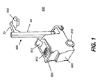
- FIG. 1 shows an example of a conventional mobile x-ray apparatus that can be employed for computed radiography (CR) and/or digital radiography (DR).
- a mobile radiography unit 600 has a frame 620 that includes a display 610 for display of obtained images and related data and a control panel 612 that allows functions such as storing, transmitting, modifying, and printing of the obtained image.
- unit 600 For mobility, unit 600 has one or more wheels 615 and one or more handle grips 625, typically provided at waist-, arm-, or hand-level, that help to guide unit 600 to its intended location.
- a self-contained battery pack typically provides source power, eliminating the need for operation near a power outlet.
- support member 635 that supports an x-ray source 640, also termed an x-ray tube or tube head, mounted on a boom apparatus 70, more simply termed a boom 70.
- a generator may also be mounted adjacent the tube head or, alternately, within frame 620.
- support member 635 has a vertical column 64 of fixed height.
- Boom 70 extends outward a variable distance from support member 635 and rides up and down column 64 to the desired height for obtaining the image. Boom 70 may extend outward by a fixed distance or may be extendible over a variable distance.
- Height settings for the x-ray source 640 can range from low height for imaging feet and lower extremities to shoulder height and above for imaging the upper body portions of patients in various positions.
- the support member for the x-ray source is not a fixed column, but is rather an articulated member that bends at a joint mechanism to allow movement of the x-ray source over a range of vertical and horizontal positions.
- the two-dimensional image-sensing device itself is a portable cassette that stores the readable imaging medium.
- DR direct digital radiography
- the two-dimensional image-sensing receiver is a digital detector with either flat, rigid, or flexible substrate support.
- the receiver itself may not be visible to the technician once it is positioned behind the patient. This complicates the alignment task for portable systems, requiring some method for measuring SID, tilt angle, and centering, and making it more difficult to use a grid effectively for reducing the effects of scatter. Because of this added complexity with a portable radiography system, the technician may choose not to use a grid; the result without a grid, however, is typically a lower-quality image.
- US 2009 136 000 A1 discloses an imaging apparatus in which positions of an X-ray image and optical image of a subject can be brought into registration with each other.
- a half-mirror is provided between the X-ray source and subject and is configured to pass X-rays and reflect visible light.
- a TV camera captures the optical image of the surface of the subject reflected by the half-mirror.
- a display unit displays the optical image captured by the TV camera together with a reference mark indicating the reference position of this optical image, and also displays, in superimposed form, an X-ray image using an X-ray imaging unit.
- US 2006 109 958 A1 discloses an x-ray detector and x-ray tube equipped with sensors that communicate to provide feedback as to the orientation of an x-ray tube and x-ray detector.
- the x-ray tube may be equipped with transceivers designed to emit multiple beams toward multiple sensors in the x-ray detector.
- the sensors in the x-ray detector receive a corresponding beam from the x-ray tube transmitters, it is deemed that the detector is properly aligned relative to the x-ray tube. It is also possible to not only measure the incidence but also magnitude of a received signal to achieve a proper distance between the x-ray detector and x-ray tube for data acquisition.
- the '143 and '578 MacMahon disclosures require that a fixed Source-to-Image Distance (SID) be determined beforehand, then apply triangulation with this fixed SID value. Changing the SID requires a number of adjustments to the triangulation settings. This arrangement is less than desirable for portable imaging systems that allow a variable SID. Devices using lasers, such as that described in the '522 Cumings disclosure, in some cases can require much more precision in making adjustments than is necessary.
- SID Source-to-Image Distance
- the solutions noted above are often of little of no value where the receiver and its accompanying grid are hidden from view, lying fully behind the patient as may be the case, for example, for chest x-ray imaging with a portable system.
- Today's portable radiation imaging devices allow considerable flexibility for placement of the film cassette, CR cassette, or Digital Radiography DR receiver by the radiology technician.
- the patient need not be in a horizontal position for imaging, but may be at any angle, depending on the type of image that is needed and on the ability to move the patient for the x-ray examination.
- the technician can manually adjust the position of both the cassette or receiver and the radiation source independently for each imaging session.
- an alignment apparatus for obtaining the desired angle between the radiation source and the grid and image receiver must be able to adapt to whatever orientation is best suited for obtaining the image.
- Tilt sensing as has been conventionally applied and as is used in the device described in US 7 156 553 A entitled "Portable Radiation Imaging System and a Radiation Image Detection Device Equipped with an Angular Signal Output Means" to Tanaka et al. and elsewhere, does not provide sufficient information on cassette-to-radiation source orientation, except in the single case where the cassette lies level. More complex position sensing devices can be used, but can be subject to sampling and accumulated rounding errors that can grow worse over time, requiring frequent resynchronization.
- Still other problems relate to the need to achieve a source-to-image distance (SID) that is well-suited for the image to be obtained and for the grid used.
- SID source-to-image distance
- Conventional alignment solutions do not provide SID information, leaving it to the technician to make separate measurements or to make an approximate SID adjustment.
- conventional solutions do not provide the technician with tools to help reduce backscatter, caused by misalignment or poor adjustment of the collimator blades.
- This type of scatter while not particularly problematic with other types of radiographic imaging, such as dental and mammographic imaging, can be troublesome with portable radiographic imaging apparatus, since the radiation is directed over a broad area. Radiation that works past the imaging receiver and any blocking element associated with the receiver can inadvertently be reflected back into the receiver, adversely affecting image quality.
- the technician is required to estimate the location and orientation or outline of the imaging receiver and to adjust the collimator accordingly.
- An object of the present invention is to advance the art of radiographic imaging by providing apparatus and methods to aid in alignment and proper positioning of the radiation source to a radiation receiver.
- a related object of the present invention is to provide a display that indicates the location and outline of the radiation receiver relative to the path of the x-ray beam, as well as source-to-image distance and angular orientation of the receiver relative to the source. The display may appear on a display monitor or may be projected directly onto the patient.
- a radiography system for obtaining a radiographic image of a subject, the system comprising a radiation source energizable to direct radiant energy along a radiation path; an imaging receiver sensitive to the radiant energy for forming the radiographic image; a sensor apparatus that is disposed to provide one or more output signals that are indicative at least of centering of the radiation path with respect to the receiver, of an angle of the receiver relative to the radiation path, and of a source-to-image distance along the radiation path; and a display apparatus configured to generate and display, in response to the one or more output signals, a display that indicates information defining the centering of the radiation path with respect to the receiver including adjustments needed for proper centering and text information defining an amount of centering error in terms of distance measured, and that provides one or more numerical values identifying the source-to-image distance in terms of distance measured and the angular measurement between the imaging receiver and the radiation source relative to a desired angle along the radiation path.
- a method for obtaining a radiographic image of a subject comprising obtaining one or more signals indicative of centering of an imaging receiver with respect to a radiation path from a radiation source, of an angle of the receiver relative to the radiation path, and of a source-to-image distance along the radiation path; and generating, in response to the one or more obtained signals, a display that shows at least the centering of the imaging receiver, an adjustment needed for proper centering, and text information defining an amount of centering error in terms of distance measured, and displaying one or more values indicative of the source-to-image distance in terms of distance measured, and an angular measurement between the imaging receiver and the radiation source relative to a desired angle.
- imaging receiver may include a cassette that has a photostimulable medium, such as a film or phosphor medium, for example, or may include a detector array that records an image according to radiation emitted from the radiation source.
- the term "energizable” indicates a device or set of components that perform an indicated function upon receiving power and, optionally, upon receiving an enabling signal.
- FIG. 2A shows components of a radiographic imaging apparatus 30.
- a radiation source 20, such as an x-ray source, directs radiation toward a patient 14.
- a receiver 10 positioned behind the patient forms the diagnostic image from the incident radiation passing through patient 14.
- Receiver 10 may have a photostimulable medium, such as a film or phosphor medium, for example, or may have a detector array that records an image according to radiation emitted from radiation source 20.
- Receiver 10 may have landscape or portrait orientation.
- An optional antiscatter grid 12 has plates 18 arranged as shown in Figure 1A , just above the surface of the receiver 10.
- Radiation source 20 has a collimator 22 that defines the radiation field that is directed outward from source 20, toward receiver 10 in the example of Figure 2A .
- Radiation source 20 has an adjustable angular orientation for directing radiation toward receiver 10.
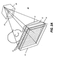
- Figure 2B shows coordinate xyz axes.
- the source-to-image distance (SID) is in the general direction of the z axis.
- radiation source 20 is in its aligned position, at a suitable SID from receiver 10.
- Grid plates 18 are angularly arranged so that they define a focal line L where their respective planes converge at the SID.
- radiation source 20 should be centered near focal line L and have the face portion of collimator 22 generally parallel to the planar surface of receiver 10.
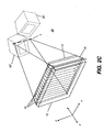
- Figure 2C shows phantom outlines at 20' and 20" for poor positioning of radiation source 20.
- the SID is almost acceptable; however, radiation source 20 is not centered near focal line L and its angular orientation is badly skewed. Alignment of the radiation source with the grid would be poor at these and similar out-of-alignment positions, degrading image quality or, at worst, preventing a suitable diagnostic image from being obtained.
- FIG. 3A and side view of Figure 3B show the use of a sensor apparatus 40 that is energizable to sense the relative spatial relationship between radiation source 20 having a radiation path represented as path R and distributed about a central axis and imaging receiver 10 sensitive to radiant energy and positioned adjacent the subject for forming the radiographic image and to generate one or more output signals indicative of the relative spatial relationship.
- a holder 46 has one or more electromagnetic coils 42 that generate an electromagnetic field or signal that is detected by one or more sensor elements 44, shown mounted near collimator 22. Holder 46 also holds receiver 10.
- sensor apparatus 40 components are built into receiver 10.
- signals are generated from one or more components on collimator 22 and detected by sensor elements on receiver 10.
- An additional inclinometer 28 or other device for obtaining an angular measurement can be provided on either or both receiver 10 or radiation source 20.
- SOD Source-to-object distance
- the position-sensing signal can be an analog signal or signals or one or more data values, for example.
- Signals can be from any of a number of types of sensor and sensor-reader apparatus, including inclinometers, radiofrequency devices, electromagnetic coils, and audio signals, for example.
- Sensors can be located in corners of the grid, holder or the receiver, or may be integrated into the grid, holder or receiver design itself. Whatever sensor configuration is used, the one or more position-sensing signals from sensor apparatus 40 go to a control logic processor 48 that provides the control logic for a display apparatus 50.
- Display apparatus 50 is energizable to generate, in response to the position-sensing signals, a display that shows the technician the disposition of receiver 10 relative to radiation path R.
- display apparatus 50 has both a display screen 52 that forms a displayed image to assist alignment and a projector 54 that forms a display by projection, wherein the projected display includes information to assist adjustment by projecting an image to indicate receiver location and related information.
- Display apparatus 50 may be equipped with either or both projector 54 and display screen 52 devices.
- numeric SID and angular orientation values appear only on display screen 52, with centering data displayed using projector 54. Alternately, SID and angular orientation values can be projected onto the patient along with a centering target.
- SID value can be particularly useful for radiographic imaging such as thoracic imaging, since there is an inverse squared relationship between the SID and the amount of radiation that is incident at the receiver.
- the SID value is generally not a concern to the operator when obtaining dental and mammographic images, since close distances are used, with positioning and tolerances dictated by the design of existing radiological equipment and by conventional practices used for those types of imaging.
- Projector 54 shown mounted on the x-ray source 20 in Figures 3B and following, may be a pico-projector, such as a Pico Projector Display from Microvision Inc., Redmond, WA, USA, or a Micro Projector from AAXA Technologies, Inc., Santa Ana, CA, for example.
- Image forming devices such as these are advantaged for a number of reasons, including small size, low weight, and low power requirements.
- These small-footprint projectors currently used in cell-phone and other highly portable electronic devices, scan one or more low-power solid-state light sources, such as light-emitting diodes (LEDs) or lasers onto a display surface. This type of projector requires a small number of optical components for projection over a range of distances.
- LEDs light-emitting diodes
- the solid-state light source itself can typically be turned on and off rapidly as needed, so that power is consumed only for those image pixels that are projected. This allows the display device to operate at low power levels, so that battery power could be used for projector 54.
- Alternate embodiments use other types of electronic imaging projectors as image forming apparatus, such as those that employ a digital micromirror array such as the Digital Light Processor (DLP) from Texas Instruments, Inc.; an array of micro-electromechanical grating light valves, such as the Grating Light Valve (GLV) device from Silicon Light Machines, Inc.; or a liquid crystal device (LCD) including a Liquid Crystal on Silicon (LCOS) device.
- projector 54 is provided by a light source and a movable target, with a motor or other actuator that moves the target, where the target is positioned in the path of the light source for providing an image that shows the receiver location.
- FIG. 4 show how projector 54 performs the display function according to one embodiment of the present invention.
- Projector 54 can project light to form images over an image field 58 that exceeds the area of receiver 10, as shown at left.
- projector 54 displays a receiver pattern 60 on patient 14, wherein receiver pattern 60 indicates at least an outline showing the location of receiver 10 behind or underneath patient 14.
- the desired alignment is shown, wherein a collimator pattern 62, emitted from the collimator light source in the x-ray tube head, is aligned with receiver pattern 60.
- projector 54 can project an image over an area that exceeds the size of receiver 10, enabling the outline of receiver 10 to be displayed prior to centering of the collimator and radiation path onto receiver 10.
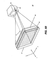
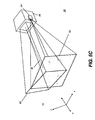
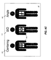
- the perspective view of Figure 5A shows collimator pattern 62 that is displayed from radiation source 20 in a spatial arrangement wherein the radiation path of radiation source 20 (centered along axis R as described previously) is not aligned with receiver 10 or its grid 12.
- the perspective view of Figure 5B shows projector 54 in display apparatus 50, projecting receiver pattern 60 directly at receiver 10.
- Figure 5C shows the overlaid paths and mismatched patterns 60 and 62 that indicate poor alignment between radiation source 20 and receiver 10.
- the perspective view of Figure 5D then shows correct alignment, wherein receiver pattern 60 and collimator pattern 62 are center-aligned and symmetrical. It can be observed that parallax problems between projector 54 and the collimator pattern 62 can be encountered when the SID is incorrect, with receiver 10 either too far or too near with respect to radiation source 20.
- Projector 54 focus can be achieved in a number of ways. Laser projectors do not need focus adjustment. Autofocus apparatus can be used for other projector types, using a range-finding signal such as an ultrasonic signal or infrared (IR) light, for example, to measure the distance from the source to the subject being imaged.
- Figure 4 shows an autofocus apparatus 112 that is in signal communication with projector 54 for determining distance to the subject. Autofocus and range-finding methods and devices are inexpensive and well-known to those skilled in the image capture arts. Alternately, information from sensor apparatus 40 can be used to determine the focus distance and used for automatic focusing.
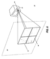
- FIG. 6 The perspective view of Figure 6 shows the projector field 58, having an area that exceeds the size of the projected pattern 60. This capability allows projector 54 to display the needed information for source-to-receiver alignment.
- the adjustments needed relate to the spatial relationship between the radiation source 20 and receiver 10 with respect to parameters such as aim centering and angle of the receiver relative to the radiation path, and of source-to-image distance along to the radiation path.
- Display of the receiver outline is also of value for making collimator adjustments that reduce backscatter.
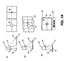
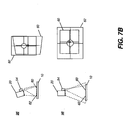
- FIG. 7A shows how alignment of collimator pattern 62 from the collimator light with receiver pattern 60 from projector 54 indicates needed alignment adjustment of radiation source 20 with its receiver 10.
- the patterns shown at 60 and 62 are representative examples selected for illustration and can take any of a number of forms, including, but not limited to, crosshair patterns, including crosshair patterns with or without a central circle as shown in the example of Figures 7A and 7B .
- source 20 and receiver 10 are not aligned and respective patterns 62 and 60 indicate this misalignment.
- source 20 is closer to alignment with receiver 10, closer to centering than shown at position 90, and patterns 62 and 60 display as somewhat overlapping but are not centered with respect to each other.
- patterns 62 and 60 display as somewhat overlapping but are not centered with respect to each other.
- source 20 and receiver 10 are aligned and the displayed respective patterns 62 and 60 are overlaid to indicate this centering alignment.
- position 94 with both patterns 60 and 62 at the same size and over substantially the same area, also indicates that the collimator has been properly set to limit the radiation distribution and to reduce the likelihood of backscatter.
- Values 66 for SID and angle are also displayed by projector 54.
- a source-to-object distance (SOD) also displays.
- the projected values can be positioned within or outside receiver pattern 60.
- additional information on properly sizing and orienting the collimated light beam can also be provided in the display.
- Figure 7B shows other examples that represent poor relative positioning of source 20 and receiver 10.
- source 20 is nearly centered with respect to receiver 10, but the angle is skewed from normal.
- Receiver pattern 60 is accordingly non-rectangular, such as having a keystone pattern, for example, indicating the angular relationship of the radiation path from source 20 and receiver 10.
- SID source-to-image distance
- the respective patterns 60 and 62 appear to be of different sizes to indicate the need for SID adjustment.
- projection is used for display apparatus 50, in addition to the receiver 10 outline, information of various types can be displayed on or alongside the patient, for example:
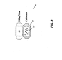
- Figure 8 shows display screen 52 that can supplement or substitute for projector 54 in an alternate embodiment of display apparatus 50.
- display screen 52 is mounted near collimator 22 as shown, so that the operator can view displayed results while moving radiation source 20 into position.
- the alignment utility may be provided on a removable or remote display screen or on display 610 ( Figure 1 ), the display console that is part of radiographic imaging apparatus 30 itself.
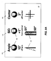
- Figures 9A , 9B , and 9C show operator interface examples when using display screen 52 as display apparatus 50.
- Various graphical icons and images are used to symbolize the adjustments needed for proper centering, angulation, and SID.
- An angle adjust indicator 100 provides various graphical and measured data to help guide proper angular adjustment of the source 20 to receiver 10.
- Angular information displays one or more of the following:
- a SID indicator 110 lists not only the current SID value obtained from measured data, but, in the embodiment shown, also shows the amount of adjustment needed.
- a centering indicator 120 provides text and graphical information on centering error and needed adjustment direction.
- centering indicator 120 includes a graphic element 104 that shows the portrait/landscape orientation of the receiver. Icons 102 use color, animation, including flashing or video clips, and symbols of different types to indicate the needed adjustment direction for the corresponding value. Graphic elements 104 are also provided to help visually indicate the adjustment needed. Graphic elements 104 can be any of a number of types of suitable element, including circles, bars, or other shapes.
- Color can be used to indicate correct angular, centering, or distance values, with differences in color indicating the recommended direction of needed change, if any, and color transitions indicating movement between positions.
- Various thresholds are used to determine how close an adjustment is to a desired setting.
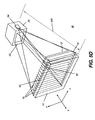
- Figure 10 shows a plan view of an alternate embodiment for the operator interface on display screen 52.
- SID indicator 110 lists the current SID value obtained from measured data.
- graphic elements 104 include sliders that show the relative amount of adjustment that is needed for centering, distance, and angle. Centering of the slider indicates correct positioning.
- Angle adjust indicator 100 shows the measured angular values for the receiver or x-ray source relative to true horizontal or, optionally, relative to each other or to a preferred setting. In an optional embodiment, the difference between their relative angles is displayed.
- Centering indicator 120 shows an image or outline of receiver 10, such as at portrait or landscape orientation, with a superimposed icon 122 that shows the relative position and shape of the x-ray beam.
- Control buttons 124 provide useful utilities for improving alignment, obtaining information about the system or about system components, and other functions.
- one of the control buttons 124 is used to set up the view type for the upcoming radiographic image (such as, for example, an AP chest exam view type) and to indicate the type of grid used, if any. This setup can then cause specific SID and angle values to be assigned and displayed for the image.
- Figure 11 shows a sequence of operator interface display screens for a display screen 52 that is mounted near collimator 22 and that changes orientation as radiation source 20 angle changes.
- a receiver icon 132 displays, along with a centering target icon 134 and a radiation source icon 136.
- centering is partially achieved, but the radiation source 20 must be redirected toward the receiver.
- a SID icon 152 graphically shows that radiation source distance to the receiver must be adjusted. SID icon 152 changes position as the SID changes.
- a position 160 proper centering, angle, and SID are obtained.
- the SID value displays as shown at SID indicator 110.
- display apparatus 50 provides considerable information relative to the position of the x-ray source and receiver, as well as other types of information that may be relevant to the imaging session. This may include date, time, temperature or other environmental conditions, information about the radiography unit itself, such as identification number, serial number, or manufacturer and model identification. In one embodiment, instructions, recommendations, or warning information are also provided to assist the operator in making needed adjustments or obtaining the image, including information on what type of image has been ordered and suggested setup and exposure values. Detector information can also be displayed. Patient identifying data can be listed, including name, age or date of birth, patient number, room number, information on measured values or patient blood type, and the like.
- the capability for editing or input by the operator may also be provided, including entry or editing of desired exposure setup values, such as generator values, including kVp, mA, mAs, time, ECF, focal spot, collimator settings, AEC setting, grid type recommended or used, and detector type.
- desired exposure setup values such as generator values, including kVp, mA, mAs, time, ECF, focal spot, collimator settings, AEC setting, grid type recommended or used, and detector type.
- a worklist that provides a job listing of images and views requested from this patient is also displayed in one embodiment.
- display screen 52 also shows acquired images for the patient and allows editing or annotation by the technician for those images.
- Values displayed on display screen 52 include relevant alignment information, such as any or all of the following, displayed in symbolic, icon, or text form:
- sensors are also able to indicate whether or not grid 12 is used and, if so, the type of grid 12 that is being used.
- the system can then display the following information on display screen 52 or projected onto the patient:
- system logic can automatically select the correct view for the exam or change the existing view to a different one. For example, the system can switch from a non-grid view to a grid view. This new view may have a different name, different exposure parameters or techniques, and different image processing parameters.
- the image type or view is determined and one or more appropriate settings for centering, angle, and SID are automatically assigned based on the view type.
- the view can be set up by the operator, such as using display screen 52 and may specify the type of grid used.
- the view can be determined from measured data, such as inclinometer readings, for example.
- an inclinometer 28 reading can indicate a supine view and a sensor apparatus 40 reading can indicate the detection of a specific grid type. This information is then used by control logic processor 48 to determine and display a suitable SID value.
- detection of receiver 10 in an upright position indicates that a longer SID can be used for a given grid type.
- an instruction on view type can be entered by the operator or technician and appropriate predetermined values for the source-to-image distance or the angle or both can be displayed or used to condition the displayed values according to the operator instruction.
- Various information detected by sensor apparatus 40 may also be stored and provided as part of the DICOM (Digital Imaging and Communications in Medicine) header information that is stored with the image data.
- DICOM Digital Imaging and Communications in Medicine
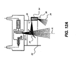
- Projector 54 can be coupled to collimator 22 in a number of ways. Referring to Figure 12A , there is shown an embodiment in which a housing 36 that holds projector 54 mounts along an edge of collimator 22.
- Projector light 34 can project over a broad angular range, but there can be slight parallax error because its light path is spaced apart from radiation path R.
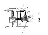
- Figure 12B uses a second mirror, two-way mirror 108, to align the path of projector light 34 with radiation path R, eliminating the parallax error condition. This arrangement allows projector 54 to project light over a broad angular range.
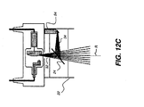
- Figure 12C replaces the existing collimator light with projector 54.
- projector 54 is aligned with radiation path R and is capable of performing a number of functions for showing centering information relative to radiation path R.
- the angular range of projection is more restricted than with the Figure 12B embodiment, but both the collimation path and receiver location can be shown within a range of angles.
- a radiography system for obtaining a radiographic image of a subject, the system comprising a radiation source energizable to direct radiant energy along a radiation path; an imaging receiver sensitive to the radiant energy for forming the radiographic image; a sensor apparatus that is disposed to provide one or more output signals that are indicative at least of the outline of the imaging receiver; and a display apparatus that generates, either by projection or on a display monitor, at least the outline of the imaging receiver, in response to the one or more output signals.
- a radiography system for obtaining a radiographic image of a subject, the system comprising a radiation source energizable to direct radiant energy along a radiation path; an imaging receiver sensitive to the radiant energy for forming the radiographic image; a sensor apparatus that is disposed to provide one or more output signals that are indicative at least of an angle of the receiver relative to the radiation path, and of a source-to-image distance along the radiation path; and a display apparatus that generates, in response to the one or more output signals, a display that provides one or more values indicative of at least the source-to-image distance and the angle of the receiver relative to the radiation path.
- the display may use either a projector or a display screen or some combination of projector and display devices. Where collimator blade position information is available, the display can also indicate alignment of the boundaries of the radiation along the radiation path to the detector outline.
Landscapes
- Health & Medical Sciences (AREA)
- Life Sciences & Earth Sciences (AREA)
- Engineering & Computer Science (AREA)
- Medical Informatics (AREA)
- Radiology & Medical Imaging (AREA)
- Molecular Biology (AREA)
- Biophysics (AREA)
- Nuclear Medicine, Radiotherapy & Molecular Imaging (AREA)
- Optics & Photonics (AREA)
- Pathology (AREA)
- Physics & Mathematics (AREA)
- Biomedical Technology (AREA)
- Heart & Thoracic Surgery (AREA)
- High Energy & Nuclear Physics (AREA)
- Surgery (AREA)
- Animal Behavior & Ethology (AREA)
- General Health & Medical Sciences (AREA)
- Public Health (AREA)
- Veterinary Medicine (AREA)
- Human Computer Interaction (AREA)
- Apparatus For Radiation Diagnosis (AREA)
Applications Claiming Priority (4)
| Application Number | Priority Date | Filing Date | Title |
|---|---|---|---|
| US32347610P | 2010-04-13 | 2010-04-13 | |
| US201161449932P | 2011-03-07 | 2011-03-07 | |
| US13/083,860 US8827554B2 (en) | 2010-04-13 | 2011-04-11 | Tube alignment for mobile radiography system |
| PCT/US2011/032020 WO2011130198A2 (en) | 2010-04-13 | 2011-04-12 | Tube alignment for mobile radiography system |
Publications (3)
| Publication Number | Publication Date |
|---|---|
| EP2557997A2 EP2557997A2 (en) | 2013-02-20 |
| EP2557997A4 EP2557997A4 (en) | 2014-04-09 |
| EP2557997B1 true EP2557997B1 (en) | 2015-08-05 |
Family
ID=52358433
Family Applications (1)
| Application Number | Title | Priority Date | Filing Date |
|---|---|---|---|
| EP11769395.2A Not-in-force EP2557997B1 (en) | 2010-04-13 | 2011-04-12 | Tube alignment for mobile radiography system |
Country Status (6)
| Country | Link |
|---|---|
| US (2) | US8827554B2 (enExample) |
| EP (1) | EP2557997B1 (enExample) |
| JP (1) | JP2013523396A (enExample) |
| KR (1) | KR20130057991A (enExample) |
| CN (1) | CN102917646B (enExample) |
| WO (1) | WO2011130198A2 (enExample) |
Families Citing this family (57)
| Publication number | Priority date | Publication date | Assignee | Title |
|---|---|---|---|---|
| US9770366B2 (en) | 2009-07-15 | 2017-09-26 | Tusker Medical, Inc. | Tympanic membrane pressure equalization tube delivery system |
| ES2646819T3 (es) * | 2010-05-12 | 2017-12-18 | Trophy | Aparato de alineación para radiografía intrabucal dental |
| US9161727B2 (en) * | 2011-09-01 | 2015-10-20 | Hologic Inc | Independently rotatable detector plate for medical imaging device |
| WO2013072872A1 (en) * | 2011-11-18 | 2013-05-23 | Koninklijke Philips Electronics N.V. | X-ray imaging guiding system for positioning a patient |
| CN103959049B (zh) * | 2011-11-25 | 2017-10-10 | 阿里贝克斯公司 | x射线距离指示器和相关方法 |
| EP2816956B1 (en) | 2012-02-22 | 2018-01-17 | Carestream Health, Inc. | Mobile radiographic apparatus/methods with tomosynthesis capability |
| WO2014043412A1 (en) * | 2012-09-12 | 2014-03-20 | Baek Seung H | Method and apparatus for more accurate positioning of dental imaging equipment |
| EP2938260B1 (en) * | 2012-12-28 | 2019-11-06 | Koninklijke Philips N.V. | Real-time scene-modeling combining 3d ultrasound and 2d x-ray imagery |
| US20140198900A1 (en) * | 2013-01-17 | 2014-07-17 | Palo Alto Research Center Incorporated | High resolution x-ray imaging with thin, flexible digital sensors |
| JP6176832B2 (ja) * | 2013-04-18 | 2017-08-09 | 東芝メディカルシステムズ株式会社 | 支持器及びx線診断装置 |
| JP6196728B2 (ja) | 2013-04-23 | 2017-09-13 | コーニンクレッカ フィリップス エヌ ヴェKoninklijke Philips N.V. | ライトプロジェクションを利用したチューブ−検出器のアライメント |
| CN104173066B (zh) * | 2013-07-31 | 2015-09-02 | 上海联影医疗科技有限公司 | 检测x射线摄影系统源像距的方法 |
| CN105473074B (zh) | 2013-08-05 | 2019-06-14 | 皇家飞利浦有限公司 | 用于移动射线照相系统的管对准功能 |
| JP6381966B2 (ja) * | 2014-05-14 | 2018-08-29 | キヤノンメディカルシステムズ株式会社 | 医用画像診断装置 |
| DE102015205096A1 (de) * | 2014-05-19 | 2015-11-19 | Siemens Aktiengesellschaft | Visualisierung eines Röntgenstrahlungsbereiches |
| CN107072609A (zh) * | 2014-08-19 | 2017-08-18 | 皇家飞利浦有限公司 | X射线成像装置 |
| KR102328118B1 (ko) | 2014-11-24 | 2021-11-18 | 삼성전자주식회사 | 엑스선 장치 및 시스템 |
| US10098609B2 (en) | 2014-12-12 | 2018-10-16 | Samsung Electronics Co., Ltd. | X ray apparatus and method of operating the same |
| KR102340197B1 (ko) * | 2015-02-03 | 2021-12-16 | 삼성전자주식회사 | 엑스선 장치 및 엑스선 장치의 동작 방법 |
| JP6412815B2 (ja) * | 2015-02-26 | 2018-10-24 | 富士フイルム株式会社 | 放射線画像撮影システム、撮影台、及び撮影方法 |
| WO2016195684A1 (en) * | 2015-06-04 | 2016-12-08 | Siemens Healthcare Gmbh | Apparatus and methods for a projection display device on x-ray imaging devices |
| CN107708569B (zh) * | 2015-06-22 | 2021-01-12 | 富士胶片株式会社 | 放射线照射装置、放射线照射装置的控制方法及存储介质 |
| EP3108815B1 (en) | 2015-06-23 | 2020-03-11 | Samsung Electronics Co., Ltd. | X-ray apparatus and controlling method of the same |
| KR102424381B1 (ko) * | 2015-07-17 | 2022-07-25 | 주식회사 레이언스 | 의료용 엑스선 영상 촬영 장치의 동작 제어 방법 및 그 동작 제어 프로그램 |
| KR101798939B1 (ko) | 2015-09-08 | 2017-11-17 | 삼성전자주식회사 | 엑스선 영상 장치 및 그 제어방법 |
| US10556129B2 (en) * | 2015-10-02 | 2020-02-11 | Varian Medical Systems, Inc. | Systems and methods for treating a skin condition using radiation |
| FR3044200B1 (fr) * | 2015-11-23 | 2020-07-03 | Trixell | Ensemble de radiologie et procede d'alignement d'un tel ensemble |
| EP3235431B1 (en) * | 2016-04-19 | 2019-02-27 | Agfa Nv | Radiation image capturing system and method |
| CN107874768B (zh) | 2016-09-30 | 2021-02-05 | 通用电气公司 | 移动辐射成像系统及其对齐方法 |
| WO2018109127A1 (en) * | 2016-12-15 | 2018-06-21 | Koninklijke Philips N.V. | Visualizing collimation errors |
| WO2018183160A1 (en) | 2017-03-27 | 2018-10-04 | Carestream Health, Inc. | Bedside dynamic imaging |
| US10568602B2 (en) | 2017-09-06 | 2020-02-25 | General Electric Company | Virtual positioning image for use in imaging |
| US10531850B2 (en) | 2017-09-07 | 2020-01-14 | General Electric Company | Mobile X-ray imaging with detector docking within a spatially registered compartment |
| EP3473186A1 (en) * | 2017-10-18 | 2019-04-24 | Koninklijke Philips N.V. | Radiation target indication |
| KR102190031B1 (ko) * | 2017-11-07 | 2020-12-11 | 삼성전자주식회사 | 엑스선 영상 장치 및 그 제어방법 |
| CN107990853B (zh) * | 2018-01-03 | 2019-11-22 | 东软医疗系统股份有限公司 | 一种源像距检测方法和装置 |
| JP7554746B2 (ja) * | 2018-08-01 | 2024-09-20 | オクソス メディカル,インコーポレイテッド | 改良された撮像方法 |
| JP7243090B2 (ja) * | 2018-09-10 | 2023-03-22 | コニカミノルタ株式会社 | 放射線撮影システム |
| WO2020067323A1 (ja) * | 2018-09-27 | 2020-04-02 | 富士フイルム株式会社 | 放射線撮影装置 |
| CN111096759A (zh) * | 2018-10-26 | 2020-05-05 | 深圳迈瑞生物医疗电子股份有限公司 | X射线摄影系统及其平板探测器、相关方法 |
| EP3936052A1 (en) * | 2020-07-07 | 2022-01-12 | Koninklijke Philips N.V. | User interface for x-ray tube-detector alignment |
| US11779290B2 (en) * | 2020-10-09 | 2023-10-10 | Shimadzu Corporation | X-ray imaging system and x-ray imaging apparatus |
| JP2022063223A (ja) * | 2020-10-09 | 2022-04-21 | 株式会社島津製作所 | X線撮影システムおよびx線撮影装置 |
| JP7533188B2 (ja) * | 2020-12-14 | 2024-08-14 | コニカミノルタ株式会社 | 放射線撮影システム、放射線撮影方法及びプログラム |
| EP4014879A1 (en) * | 2020-12-16 | 2022-06-22 | Koninklijke Philips N.V. | Field of view visualization for phase contrast x-ray imaging systems |
| JP7484703B2 (ja) * | 2020-12-25 | 2024-05-16 | 株式会社島津製作所 | X線撮像装置およびx線撮像装置用位置ずれ検知ユニット |
| EP4312773A1 (en) * | 2021-03-23 | 2024-02-07 | Carestream Health, Inc. | Physiological analysis from video x-ray imaging |
| US20220326165A1 (en) * | 2021-04-07 | 2022-10-13 | Jst Power Equipment, Inc. | Rapid x-ray radiation imaging system and mobile imaging system |
| US12196856B2 (en) * | 2021-06-09 | 2025-01-14 | Wright Medical Technology | Alignment systems and methods |
| US11382582B1 (en) | 2021-08-02 | 2022-07-12 | Oxos Medical, Inc. | Imaging systems and methods |
| KR102378300B1 (ko) * | 2021-08-05 | 2022-03-25 | 주식회사 포스콤 | 엑스선 촬영장치 |
| JP2023142507A (ja) * | 2022-03-25 | 2023-10-05 | 株式会社島津製作所 | X線撮影装置およびx線撮影装置用位置決め支援ユニット |
| CN114531767B (zh) | 2022-04-20 | 2022-08-02 | 深圳市宝润科技有限公司 | 一种手持式x光机可视化x射线定位方法及系统 |
| WO2023214762A1 (ko) | 2022-05-02 | 2023-11-09 | 재단법인 아산사회복지재단 | 혈관 영상의 캘리브레이션 방법 및 장치 |
| CN115153614B (zh) * | 2022-07-27 | 2025-04-04 | 武汉迈瑞生物医疗科技有限公司 | X射线摄影系统的动态摆位指示方法及系统 |
| US12496024B2 (en) | 2023-11-28 | 2025-12-16 | Rad Physics, Inc. | Digital mobile radiography systems and methods |
| KR102824460B1 (ko) * | 2024-12-23 | 2025-06-24 | (주)시닉스레이 | 인공지능 기반 이미지 처리 및 영상 분석을 이용한 콜리메이터 제어 장치 및 그 방법 |
Family Cites Families (57)
| Publication number | Priority date | Publication date | Assignee | Title |
|---|---|---|---|---|
| US4017858A (en) | 1973-07-30 | 1977-04-12 | Polhemus Navigation Sciences, Inc. | Apparatus for generating a nutating electromagnetic field |
| DE2817391A1 (de) | 1978-04-20 | 1979-10-31 | Siemens Ag | Roentgenaufnahmevorrichtung |
| US4836671A (en) | 1985-04-08 | 1989-06-06 | Charles Lescrenier | Locating device |
| US4752948A (en) | 1986-12-01 | 1988-06-21 | University Of Chicago | Mobile radiography alignment device |
| US6405072B1 (en) | 1991-01-28 | 2002-06-11 | Sherwood Services Ag | Apparatus and method for determining a location of an anatomical target with reference to a medical apparatus |
| US5241578A (en) | 1991-12-02 | 1993-08-31 | Arch Development Corporation | Optical grid alignment system for portable radiography and portable radiography apparatus incorporating same |
| JP3456718B2 (ja) | 1993-01-27 | 2003-10-14 | 株式会社東芝 | X線撮影装置 |
| US5388143A (en) | 1993-11-26 | 1995-02-07 | Arch Development Corporation | Alignment method for radiography and radiography apparatus incorporating same |
| US5550889A (en) | 1994-11-28 | 1996-08-27 | General Electric | Alignment of an x-ray tube focal spot using a deflection coil |
| US5617462A (en) | 1995-08-07 | 1997-04-01 | Oec Medical Systems, Inc. | Automatic X-ray exposure control system and method of use |
| US5949811A (en) | 1996-10-08 | 1999-09-07 | Hitachi Medical Corporation | X-ray apparatus |
| US5751783A (en) | 1996-12-20 | 1998-05-12 | General Electric Company | Detector for automatic exposure control on an x-ray imaging system |
| US6175610B1 (en) * | 1998-02-11 | 2001-01-16 | Siemens Aktiengesellschaft | Medical technical system controlled by vision-detected operator activity |
| US6047042A (en) | 1998-03-25 | 2000-04-04 | Continental X-Ray Corporation | Automatic exposure and brightness control for fluoroscopic and radio-graphic imaging |
| JP2000023955A (ja) | 1998-07-14 | 2000-01-25 | Canon Inc | 放射線撮影装置 |
| JP4383558B2 (ja) | 1998-07-21 | 2009-12-16 | 東芝医用システムエンジニアリング株式会社 | X線診断装置及び放射線診断装置 |
| US6192105B1 (en) | 1998-11-25 | 2001-02-20 | Communications & Power Industries Canada Inc. | Method and device to calibrate an automatic exposure control device in an x-ray imaging system |
| US6154522A (en) | 1999-02-11 | 2000-11-28 | Mcdonnell Douglas Corporation | Method, system and apparatus for aiming a device emitting a radiant beam |
| JP2001061861A (ja) | 1999-06-28 | 2001-03-13 | Siemens Ag | 画像撮影手段を備えたシステムおよび医用ワークステーション |
| US6404851B1 (en) | 2000-03-30 | 2002-06-11 | General Electric Company | Method and apparatus for automatic exposure control using localized capacitive coupling in a matrix-addressed imaging panel |
| US6327336B1 (en) | 2000-06-05 | 2001-12-04 | Direct Radiography Corp. | Radiogram showing location of automatic exposure control sensor |
| EP1228384B1 (en) | 2000-09-20 | 2012-03-28 | Koninklijke Philips Electronics N.V. | Exposure control in an x-ray image detector |
| JP2002143139A (ja) | 2000-11-15 | 2002-05-21 | Fuji Photo Film Co Ltd | 可搬型の放射線画像撮影システムおよび該システムに使用される放射線画像検出装置 |
| US6422750B1 (en) | 2000-12-22 | 2002-07-23 | Ge Medical Systems Global Technology Company, Llc | Digital x-ray imager alignment method |
| US6702459B2 (en) | 2001-04-11 | 2004-03-09 | The Uab Research Foundation | Mobile radiography system and process |
| US6795526B2 (en) | 2002-03-04 | 2004-09-21 | Ge Medical Systems Global Technology Co., Llc | Automatic exposure control for a digital image acquisition system |
| SE522162C2 (sv) | 2002-05-06 | 2004-01-20 | Goergen Nilsson | Metod att utföra in vivo-dosimetri vid IMRT-behandling |
| JP3647440B2 (ja) | 2002-05-28 | 2005-05-11 | キヤノン株式会社 | X線撮影装置 |
| DE10234465A1 (de) | 2002-07-29 | 2004-02-12 | Siemens Ag | Verfahren zur Schichthöhenpositionierung |
| US7006598B2 (en) | 2002-08-09 | 2006-02-28 | Canon Kabushiki Kaisha | Imaging method and apparatus with exposure control |
| JP4522044B2 (ja) | 2002-11-15 | 2010-08-11 | キヤノン株式会社 | 放射線撮影装置 |
| US6935779B2 (en) * | 2002-11-29 | 2005-08-30 | Ge Medical Systems Global Technology Company, Llc | Method and apparatus for aligning an X-ray source and detector at various source to image distances |
| US6950492B2 (en) | 2003-06-25 | 2005-09-27 | Besson Guy M | Dynamic multi-spectral X-ray projection imaging |
| US7697743B2 (en) | 2003-07-03 | 2010-04-13 | General Electric Company | Methods and systems for prescribing parameters for tomosynthesis |
| EP1684635B1 (en) | 2003-10-29 | 2011-07-20 | Philips Intellectual Property & Standards GmbH | Device and method for adjusting imaging parameters of an x-ray apparatus |
| JP4612796B2 (ja) | 2004-01-30 | 2011-01-12 | キヤノン株式会社 | X線撮影画像表示制御装置及び方法並びにx線撮影システム |
| EP1761954A1 (en) | 2004-06-18 | 2007-03-14 | Koninklijke Philips Electronics N.V. | X-ray image detector |
| FI118356B (fi) * | 2004-07-22 | 2007-10-15 | Planmeca Oy | Järjestely intraoraaliröntgenkuvantamisen yhteydessä |
| JP4560359B2 (ja) | 2004-09-13 | 2010-10-13 | オリンパス株式会社 | 位置検出装置、被検体内導入システムおよび位置検出方法 |
| US7581885B2 (en) | 2004-11-24 | 2009-09-01 | General Electric Company | Method and system of aligning x-ray detector for data acquisition |
| CN101940474B (zh) | 2004-12-17 | 2013-06-12 | 奥林巴斯株式会社 | 医用装置、和医用磁感应及位置检测系统 |
| DE102005036852A1 (de) * | 2005-08-04 | 2007-02-22 | Siemens Ag | Verfahren bzw. "Vorrichtung" zum Ermitteln einer Lage eines Patienten bei einem auf einem medizinischen Bildgebungsverfahren basierenden Erstellen eines Bildes eines Untersuchungsbereichs des Patienten |
| JP5666091B2 (ja) | 2005-09-08 | 2015-02-12 | コーニンクレッカ フィリップス エヌ ヴェ | イメージングシステム用磁気トラッキングシステム |
| JP4597936B2 (ja) | 2005-10-06 | 2010-12-15 | 富士フイルム株式会社 | 乳房画像撮影装置 |
| US7581884B1 (en) | 2006-02-07 | 2009-09-01 | Barnes Gary T | Mobile radiography system and grid alignment process |
| FR2899349B1 (fr) | 2006-04-04 | 2009-05-01 | Pierre Tranchant | Reglage de position d'une installation de radiologie mobile |
| CN101472523A (zh) | 2006-06-22 | 2009-07-01 | 皇家飞利浦电子股份有限公司 | X射线成像装置和对检查对象成像的方法 |
| US7313224B1 (en) | 2006-06-22 | 2007-12-25 | General Electric Co. | Wireless integrated automatic exposure control module |
| JP2010501238A (ja) | 2006-08-21 | 2010-01-21 | コーニンクレッカ フィリップス エレクトロニクス エヌ ヴィ | グリッド検知ユニットを備えた可搬式x線検出器及び可搬式x線検出器の自動露出設定のためのx線撮像システム |
| US7744279B2 (en) | 2006-11-02 | 2010-06-29 | Carestream Health, Inc. | Orientation sensing apparatus for radiation imaging system |
| JP2008125981A (ja) * | 2006-11-24 | 2008-06-05 | Shimadzu Corp | 一般撮影システム |
| JP5196798B2 (ja) | 2007-02-15 | 2013-05-15 | キヤノン株式会社 | 放射線画像投影装置および方法 |
| US7734013B2 (en) | 2007-03-26 | 2010-06-08 | Fujifilm Corporation | Radiation image capturing apparatus and method of controlling radiation image capturing apparatus |
| US20090086926A1 (en) * | 2007-09-27 | 2009-04-02 | Carestream Health, Inc. | Exposure centering apparatus for imaging system |
| JP2009131323A (ja) * | 2007-11-28 | 2009-06-18 | Canon Inc | 撮像装置 |
| EP2247240B1 (en) | 2008-01-28 | 2016-11-02 | Reflective X-ray Optics LLC | Optical alignment system and alignment method for radiographic x-ray imaging |
| US7632016B1 (en) | 2008-07-22 | 2009-12-15 | Carestream Health, Inc. | Digital detector calibration with known exposure |
-
2011
- 2011-04-11 US US13/083,860 patent/US8827554B2/en active Active
- 2011-04-12 KR KR1020127029132A patent/KR20130057991A/ko not_active Withdrawn
- 2011-04-12 JP JP2013505031A patent/JP2013523396A/ja not_active Withdrawn
- 2011-04-12 EP EP11769395.2A patent/EP2557997B1/en not_active Not-in-force
- 2011-04-12 WO PCT/US2011/032020 patent/WO2011130198A2/en not_active Ceased
- 2011-04-12 CN CN201180027634.0A patent/CN102917646B/zh active Active
-
2014
- 2014-07-31 US US14/447,695 patent/US9155509B2/en active Active
Also Published As
| Publication number | Publication date |
|---|---|
| EP2557997A4 (en) | 2014-04-09 |
| EP2557997A2 (en) | 2013-02-20 |
| WO2011130198A2 (en) | 2011-10-20 |
| US20110249793A1 (en) | 2011-10-13 |
| KR20130057991A (ko) | 2013-06-03 |
| CN102917646B (zh) | 2015-10-21 |
| WO2011130198A3 (en) | 2012-01-19 |
| CN102917646A (zh) | 2013-02-06 |
| US8827554B2 (en) | 2014-09-09 |
| US20140341349A1 (en) | 2014-11-20 |
| JP2013523396A (ja) | 2013-06-17 |
| US9155509B2 (en) | 2015-10-13 |
Similar Documents
| Publication | Publication Date | Title |
|---|---|---|
| EP2557997B1 (en) | Tube alignment for mobile radiography system | |
| US8821017B2 (en) | Projector as collimator light | |
| US20230135766A1 (en) | Automated apparatus to improve image quality in x-ray and associated method of use | |
| EP2713886B1 (en) | Method for generating an intraoral volume image | |
| KR101664528B1 (ko) | 치과 구강-내 라디오그래피용 정렬 장치 | |
| US9179886B2 (en) | Alignment apparatus for x-ray imaging system | |
| JP6434414B2 (ja) | X線透視撮影用のポータブル型ラジオグラフィ撮影装置 | |
| US20090041201A1 (en) | Alignment apparatus for imaging system | |
| US7114849B2 (en) | Medical imaging device | |
| US7806591B2 (en) | Alignment apparatus for imaging system using reflective element | |
| KR20180086709A (ko) | 엑스선 영상 장치 및 그 제어 방법 | |
| JP5442381B2 (ja) | 医用画像撮影システム | |
| JP5027711B2 (ja) | 放射線画像撮影装置及び方法並びにプログラム | |
| KR102296413B1 (ko) | 이동형 방사선 측정 시스템 및 이를 이용한 이동형 방사선 측정 방법 | |
| JP2025169730A (ja) | 放射線撮影システム |
Legal Events
| Date | Code | Title | Description |
|---|---|---|---|
| PUAI | Public reference made under article 153(3) epc to a published international application that has entered the european phase |
Free format text: ORIGINAL CODE: 0009012 |
|
| 17P | Request for examination filed |
Effective date: 20121008 |
|
| AK | Designated contracting states |
Kind code of ref document: A2 Designated state(s): AL AT BE BG CH CY CZ DE DK EE ES FI FR GB GR HR HU IE IS IT LI LT LU LV MC MK MT NL NO PL PT RO RS SE SI SK SM TR |
|
| DAX | Request for extension of the european patent (deleted) | ||
| A4 | Supplementary search report drawn up and despatched |
Effective date: 20140311 |
|
| RIC1 | Information provided on ipc code assigned before grant |
Ipc: A61B 6/08 20060101AFI20140305BHEP Ipc: A61B 6/00 20060101ALN20140305BHEP |
|
| GRAP | Despatch of communication of intention to grant a patent |
Free format text: ORIGINAL CODE: EPIDOSNIGR1 |
|
| RIC1 | Information provided on ipc code assigned before grant |
Ipc: A61B 6/00 20060101ALN20150129BHEP Ipc: A61B 6/08 20060101AFI20150129BHEP |
|
| INTG | Intention to grant announced |
Effective date: 20150213 |
|
| RAP1 | Party data changed (applicant data changed or rights of an application transferred) |
Owner name: CARESTREAM HEALTH, INC. |
|
| RIN1 | Information on inventor provided before grant (corrected) |
Inventor name: STAGNITTO, JOSEPH, E. Inventor name: LALENA, MICHAEL, C. |
|
| GRAS | Grant fee paid |
Free format text: ORIGINAL CODE: EPIDOSNIGR3 |
|
| GRAA | (expected) grant |
Free format text: ORIGINAL CODE: 0009210 |
|
| AK | Designated contracting states |
Kind code of ref document: B1 Designated state(s): AL AT BE BG CH CY CZ DE DK EE ES FI FR GB GR HR HU IE IS IT LI LT LU LV MC MK MT NL NO PL PT RO RS SE SI SK SM TR |
|
| REG | Reference to a national code |
Ref country code: GB Ref legal event code: FG4D |
|
| REG | Reference to a national code |
Ref country code: CH Ref legal event code: EP |
|
| REG | Reference to a national code |
Ref country code: AT Ref legal event code: REF Ref document number: 740210 Country of ref document: AT Kind code of ref document: T Effective date: 20150815 |
|
| REG | Reference to a national code |
Ref country code: IE Ref legal event code: FG4D |
|
| REG | Reference to a national code |
Ref country code: DE Ref legal event code: R096 Ref document number: 602011018505 Country of ref document: DE |
|
| REG | Reference to a national code |
Ref country code: AT Ref legal event code: MK05 Ref document number: 740210 Country of ref document: AT Kind code of ref document: T Effective date: 20150805 |
|
| REG | Reference to a national code |
Ref country code: LT Ref legal event code: MG4D |
|
| REG | Reference to a national code |
Ref country code: NL Ref legal event code: MP Effective date: 20150805 |
|
| PG25 | Lapsed in a contracting state [announced via postgrant information from national office to epo] |
Ref country code: LV Free format text: LAPSE BECAUSE OF FAILURE TO SUBMIT A TRANSLATION OF THE DESCRIPTION OR TO PAY THE FEE WITHIN THE PRESCRIBED TIME-LIMIT Effective date: 20150805 Ref country code: LT Free format text: LAPSE BECAUSE OF FAILURE TO SUBMIT A TRANSLATION OF THE DESCRIPTION OR TO PAY THE FEE WITHIN THE PRESCRIBED TIME-LIMIT Effective date: 20150805 Ref country code: NO Free format text: LAPSE BECAUSE OF FAILURE TO SUBMIT A TRANSLATION OF THE DESCRIPTION OR TO PAY THE FEE WITHIN THE PRESCRIBED TIME-LIMIT Effective date: 20151105 Ref country code: GR Free format text: LAPSE BECAUSE OF FAILURE TO SUBMIT A TRANSLATION OF THE DESCRIPTION OR TO PAY THE FEE WITHIN THE PRESCRIBED TIME-LIMIT Effective date: 20151106 Ref country code: FI Free format text: LAPSE BECAUSE OF FAILURE TO SUBMIT A TRANSLATION OF THE DESCRIPTION OR TO PAY THE FEE WITHIN THE PRESCRIBED TIME-LIMIT Effective date: 20150805 |
|
| PG25 | Lapsed in a contracting state [announced via postgrant information from national office to epo] |
Ref country code: HR Free format text: LAPSE BECAUSE OF FAILURE TO SUBMIT A TRANSLATION OF THE DESCRIPTION OR TO PAY THE FEE WITHIN THE PRESCRIBED TIME-LIMIT Effective date: 20150805 Ref country code: IS Free format text: LAPSE BECAUSE OF FAILURE TO SUBMIT A TRANSLATION OF THE DESCRIPTION OR TO PAY THE FEE WITHIN THE PRESCRIBED TIME-LIMIT Effective date: 20151205 Ref country code: RS Free format text: LAPSE BECAUSE OF FAILURE TO SUBMIT A TRANSLATION OF THE DESCRIPTION OR TO PAY THE FEE WITHIN THE PRESCRIBED TIME-LIMIT Effective date: 20150805 Ref country code: PL Free format text: LAPSE BECAUSE OF FAILURE TO SUBMIT A TRANSLATION OF THE DESCRIPTION OR TO PAY THE FEE WITHIN THE PRESCRIBED TIME-LIMIT Effective date: 20150805 Ref country code: SE Free format text: LAPSE BECAUSE OF FAILURE TO SUBMIT A TRANSLATION OF THE DESCRIPTION OR TO PAY THE FEE WITHIN THE PRESCRIBED TIME-LIMIT Effective date: 20150805 Ref country code: PT Free format text: LAPSE BECAUSE OF FAILURE TO SUBMIT A TRANSLATION OF THE DESCRIPTION OR TO PAY THE FEE WITHIN THE PRESCRIBED TIME-LIMIT Effective date: 20151207 Ref country code: AT Free format text: LAPSE BECAUSE OF FAILURE TO SUBMIT A TRANSLATION OF THE DESCRIPTION OR TO PAY THE FEE WITHIN THE PRESCRIBED TIME-LIMIT Effective date: 20150805 Ref country code: ES Free format text: LAPSE BECAUSE OF FAILURE TO SUBMIT A TRANSLATION OF THE DESCRIPTION OR TO PAY THE FEE WITHIN THE PRESCRIBED TIME-LIMIT Effective date: 20150805 |
|
| PG25 | Lapsed in a contracting state [announced via postgrant information from national office to epo] |
Ref country code: NL Free format text: LAPSE BECAUSE OF FAILURE TO SUBMIT A TRANSLATION OF THE DESCRIPTION OR TO PAY THE FEE WITHIN THE PRESCRIBED TIME-LIMIT Effective date: 20150805 |
|
| PG25 | Lapsed in a contracting state [announced via postgrant information from national office to epo] |
Ref country code: CZ Free format text: LAPSE BECAUSE OF FAILURE TO SUBMIT A TRANSLATION OF THE DESCRIPTION OR TO PAY THE FEE WITHIN THE PRESCRIBED TIME-LIMIT Effective date: 20150805 Ref country code: IT Free format text: LAPSE BECAUSE OF FAILURE TO SUBMIT A TRANSLATION OF THE DESCRIPTION OR TO PAY THE FEE WITHIN THE PRESCRIBED TIME-LIMIT Effective date: 20150805 Ref country code: DK Free format text: LAPSE BECAUSE OF FAILURE TO SUBMIT A TRANSLATION OF THE DESCRIPTION OR TO PAY THE FEE WITHIN THE PRESCRIBED TIME-LIMIT Effective date: 20150805 Ref country code: EE Free format text: LAPSE BECAUSE OF FAILURE TO SUBMIT A TRANSLATION OF THE DESCRIPTION OR TO PAY THE FEE WITHIN THE PRESCRIBED TIME-LIMIT Effective date: 20150805 Ref country code: SK Free format text: LAPSE BECAUSE OF FAILURE TO SUBMIT A TRANSLATION OF THE DESCRIPTION OR TO PAY THE FEE WITHIN THE PRESCRIBED TIME-LIMIT Effective date: 20150805 |
|
| REG | Reference to a national code |
Ref country code: DE Ref legal event code: R097 Ref document number: 602011018505 Country of ref document: DE |
|
| PG25 | Lapsed in a contracting state [announced via postgrant information from national office to epo] |
Ref country code: RO Free format text: LAPSE BECAUSE OF FAILURE TO SUBMIT A TRANSLATION OF THE DESCRIPTION OR TO PAY THE FEE WITHIN THE PRESCRIBED TIME-LIMIT Effective date: 20150805 |
|
| PLBE | No opposition filed within time limit |
Free format text: ORIGINAL CODE: 0009261 |
|
| STAA | Information on the status of an ep patent application or granted ep patent |
Free format text: STATUS: NO OPPOSITION FILED WITHIN TIME LIMIT |
|
| 26N | No opposition filed |
Effective date: 20160509 |
|
| PG25 | Lapsed in a contracting state [announced via postgrant information from national office to epo] |
Ref country code: SI Free format text: LAPSE BECAUSE OF FAILURE TO SUBMIT A TRANSLATION OF THE DESCRIPTION OR TO PAY THE FEE WITHIN THE PRESCRIBED TIME-LIMIT Effective date: 20150805 Ref country code: BE Free format text: LAPSE BECAUSE OF NON-PAYMENT OF DUE FEES Effective date: 20160430 |
|
| REG | Reference to a national code |
Ref country code: CH Ref legal event code: PL |
|
| GBPC | Gb: european patent ceased through non-payment of renewal fee |
Effective date: 20160412 |
|
| PG25 | Lapsed in a contracting state [announced via postgrant information from national office to epo] |
Ref country code: LU Free format text: LAPSE BECAUSE OF FAILURE TO SUBMIT A TRANSLATION OF THE DESCRIPTION OR TO PAY THE FEE WITHIN THE PRESCRIBED TIME-LIMIT Effective date: 20160412 Ref country code: BE Free format text: LAPSE BECAUSE OF FAILURE TO SUBMIT A TRANSLATION OF THE DESCRIPTION OR TO PAY THE FEE WITHIN THE PRESCRIBED TIME-LIMIT Effective date: 20150805 |
|
| REG | Reference to a national code |
Ref country code: IE Ref legal event code: MM4A |
|
| REG | Reference to a national code |
Ref country code: FR Ref legal event code: ST Effective date: 20161230 |
|
| PG25 | Lapsed in a contracting state [announced via postgrant information from national office to epo] |
Ref country code: FR Free format text: LAPSE BECAUSE OF NON-PAYMENT OF DUE FEES Effective date: 20160502 Ref country code: LI Free format text: LAPSE BECAUSE OF NON-PAYMENT OF DUE FEES Effective date: 20160430 Ref country code: GB Free format text: LAPSE BECAUSE OF NON-PAYMENT OF DUE FEES Effective date: 20160412 Ref country code: CH Free format text: LAPSE BECAUSE OF NON-PAYMENT OF DUE FEES Effective date: 20160430 |
|
| PG25 | Lapsed in a contracting state [announced via postgrant information from national office to epo] |
Ref country code: IE Free format text: LAPSE BECAUSE OF NON-PAYMENT OF DUE FEES Effective date: 20160412 |
|
| PG25 | Lapsed in a contracting state [announced via postgrant information from national office to epo] |
Ref country code: CY Free format text: LAPSE BECAUSE OF FAILURE TO SUBMIT A TRANSLATION OF THE DESCRIPTION OR TO PAY THE FEE WITHIN THE PRESCRIBED TIME-LIMIT Effective date: 20150805 Ref country code: SM Free format text: LAPSE BECAUSE OF FAILURE TO SUBMIT A TRANSLATION OF THE DESCRIPTION OR TO PAY THE FEE WITHIN THE PRESCRIBED TIME-LIMIT Effective date: 20150805 Ref country code: HU Free format text: LAPSE BECAUSE OF FAILURE TO SUBMIT A TRANSLATION OF THE DESCRIPTION OR TO PAY THE FEE WITHIN THE PRESCRIBED TIME-LIMIT; INVALID AB INITIO Effective date: 20110412 |
|
| PG25 | Lapsed in a contracting state [announced via postgrant information from national office to epo] |
Ref country code: MT Free format text: LAPSE BECAUSE OF NON-PAYMENT OF DUE FEES Effective date: 20160430 Ref country code: MC Free format text: LAPSE BECAUSE OF FAILURE TO SUBMIT A TRANSLATION OF THE DESCRIPTION OR TO PAY THE FEE WITHIN THE PRESCRIBED TIME-LIMIT Effective date: 20150805 Ref country code: TR Free format text: LAPSE BECAUSE OF FAILURE TO SUBMIT A TRANSLATION OF THE DESCRIPTION OR TO PAY THE FEE WITHIN THE PRESCRIBED TIME-LIMIT Effective date: 20150805 Ref country code: MK Free format text: LAPSE BECAUSE OF FAILURE TO SUBMIT A TRANSLATION OF THE DESCRIPTION OR TO PAY THE FEE WITHIN THE PRESCRIBED TIME-LIMIT Effective date: 20150805 |
|
| PG25 | Lapsed in a contracting state [announced via postgrant information from national office to epo] |
Ref country code: BG Free format text: LAPSE BECAUSE OF FAILURE TO SUBMIT A TRANSLATION OF THE DESCRIPTION OR TO PAY THE FEE WITHIN THE PRESCRIBED TIME-LIMIT Effective date: 20150805 |
|
| PG25 | Lapsed in a contracting state [announced via postgrant information from national office to epo] |
Ref country code: AL Free format text: LAPSE BECAUSE OF FAILURE TO SUBMIT A TRANSLATION OF THE DESCRIPTION OR TO PAY THE FEE WITHIN THE PRESCRIBED TIME-LIMIT Effective date: 20150805 |
|
| PGFP | Annual fee paid to national office [announced via postgrant information from national office to epo] |
Ref country code: DE Payment date: 20210318 Year of fee payment: 11 |
|
| REG | Reference to a national code |
Ref country code: DE Ref legal event code: R119 Ref document number: 602011018505 Country of ref document: DE |
|
| PG25 | Lapsed in a contracting state [announced via postgrant information from national office to epo] |
Ref country code: DE Free format text: LAPSE BECAUSE OF NON-PAYMENT OF DUE FEES Effective date: 20221103 |