EP2557660B1 - Geschichteter eisenkern einer elektrischen drehmaschine - Google Patents
Geschichteter eisenkern einer elektrischen drehmaschine Download PDFInfo
- Publication number
- EP2557660B1 EP2557660B1 EP10849442.8A EP10849442A EP2557660B1 EP 2557660 B1 EP2557660 B1 EP 2557660B1 EP 10849442 A EP10849442 A EP 10849442A EP 2557660 B1 EP2557660 B1 EP 2557660B1
- Authority
- EP
- European Patent Office
- Prior art keywords
- portions
- core
- back yoke
- electric machine
- rotary electric
- Prior art date
- Legal status (The legal status is an assumption and is not a legal conclusion. Google has not performed a legal analysis and makes no representation as to the accuracy of the status listed.)
- Active
Links
Images


Classifications
-
- H—ELECTRICITY
- H02—GENERATION; CONVERSION OR DISTRIBUTION OF ELECTRIC POWER
- H02K—DYNAMO-ELECTRIC MACHINES
- H02K1/00—Details of the magnetic circuit
- H02K1/06—Details of the magnetic circuit characterised by the shape, form or construction
- H02K1/12—Stationary parts of the magnetic circuit
- H02K1/18—Means for mounting or fastening magnetic stationary parts on to, or to, the stator structures
-
- H—ELECTRICITY
- H02—GENERATION; CONVERSION OR DISTRIBUTION OF ELECTRIC POWER
- H02K—DYNAMO-ELECTRIC MACHINES
- H02K1/00—Details of the magnetic circuit
- H02K1/06—Details of the magnetic circuit characterised by the shape, form or construction
- H02K1/12—Stationary parts of the magnetic circuit
- H02K1/14—Stator cores with salient poles
- H02K1/146—Stator cores with salient poles consisting of a generally annular yoke with salient poles
- H02K1/148—Sectional cores
Definitions
- the present invention relates to construction of a rotary electric machine laminated core, and particularly relates to improvements in characteristics and productivity of a laminated core that has a construction in which laminar core segments are stacked and integrated, and end portions thereof are joined to each other.
- Conventional rotary electric machine laminated cores are configured by linking in a circumferential direction a plurality of core blocks that are formed by stacking a plurality of core segments.
- a plurality of first core members and a plurality of second core members are stacked alternately.
- Each of the first core members is configured by linking a plurality of core segments in a single row.
- Each of the second core members is configured by linking in a single row a plurality of core segments that are oriented in a reverse direction to the core segments in the first core members.
- Each of the core segments has: a back yoke portion; a magnetic pole tooth portion that protrudes outward from the back yoke portion; a circular arc-shaped projecting portion that is disposed on a first end portion of the back yoke portion; a circular arc-shaped recess portion that is disposed on a second end portion of the back yoke portion; and a rotating shaft portion that is disposed on the circular arc-shaped projecting portion.
- Each of the core segments is coupled pivotably to an adjacent core segment by placing the projecting portion in contact with the recess portion of the adjacent core segment so as to fit together therewith (see Patent Literature 1, for example).
- the projecting portions and recess portions of the core segments are formed by punching and lancing in a die (see Patent Literature 2, for example).
- Document JP 2001-103690 A shows a stator for rotary electric machines which enables easy uniting of a plurality of split cores circularly, without having to use exclusive jigs for supporting the split cores from the beginning to the end.
- Document US 6,946,769 B2 shows an insulator for insulating the core of an electric rotating machine from coils wound around the core and a method for manufacturing the insulator, and more particularly a stator for an electric rotating machine.
- the present invention aims to solve the above problems and an object of the present invention is to provide a rotary electric machine laminated core that can be configured such that a core segment stacking step and a linking step can be performed simultaneously so as to allow for productivity, and that can also achieve improvements in characteristics such as efficiency and torque pulsation by reducing core segment machining strain, to increase material yield, and to enable manufacturing problems to be prevented.
- a rotary electric machine laminated core including a plurality of core segments that include: a back yoke portion; a magnetic pole tooth portion that protrudes outward from the back yoke portion; a projecting portion that is disposed on a first end portion of the back yoke portion; a recess portion that is disposed on a second end portion of the back yoke portion; and a rotating shaft portion that is disposed on the projecting portion, the core segments being arranged into an annular shape, and being stacked in an axial direction of a rotary electric machine, wherein: the projecting portions are abutted to the recess portions of circumferentially adjacent core segments; a first core member that is formed by sequentially arranging the core segments such that the projecting portions are oriented in a first direction relative to a direction of rotation of the rotary electric machine, and a second core member that is formed by sequentially arranging the core segments such that the
- a rotary electric machine laminated core because the notch portions are disposed in the vicinity of the rotating shaft portions of adjacent projecting portions and recess portions, and the predetermined gap that connects from the outer circumferential side to the inner circumferential side of the back yoke portions is formed between the adjacent projecting portions and recess portions when expanded rectilinearly such that the respective magnetic pole tooth portions are parallel, pressing is made possible without using lancing methods when the core segments are arranged rectilinearly, reducing machining strain, and enabling improvements in characteristics such as efficiency and torque pulsation to be achieved. The generation of scrap is also reduced, enabling productivity to be improved. In addition, since the core segments can be pressed while arranged rectilinearly on a metal sheet, material yield can be improved.
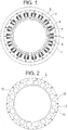
- FIG 1 is a plan that shows a rotary electric machine according to Embodiment 1 of the present invention.
- a cylindrical stator 2 is held inside a cylindrical housing 1.
- the stator 2 has: a laminated core 3; a driving coil 4 that is wound onto the laminated core 3; and insulators 5 that are interposed between the laminated core 3 and the driving coil 4.
- a rotor 6 is disposed inside the stator 2.
- the rotor 6 is held by the housing 1 so as to be rotatable relative to the stator 2.
- the rotor 6 has: a plurality of permanent magnets 7 that are fixed to an outer circumferential portion thereof, and that face the stator 2.
- Figure 2 is a plan that shows the laminated core 3 from Figure 1
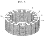
- Figure 3 is a perspective that shows the laminated core 3 from Figure 1
- Figure 4 is a plan that shows a state during assembly of the laminated core 3 from Figure 1
- the laminated core 3 is configured by combining a plurality of (in this example, two) circular arc-shaped segmented laminated cores 11 into an annular shape.
- Each of segmented laminated cores 11 is configured by linking a plurality of (in this example, nine) core blocks 12 so as to be mutually rotatable.
- Each of the core blocks 12 is configured by stacking a plurality of core segments 13 in an axial direction of the rotary electric machine.
- Figure 5 is a plan that shows a core segment 13 from Figure 4 enlarged.
- the core segment 13 has: a back yoke portion 13a that forms an annular yoke portion of the laminated core 3; and a magnetic pole tooth portion 13b that protrudes outward toward a radially inner side of the laminated core 3 from the back yoke portion 13a, and onto which the driving coil 4 is wound.
- a projecting portion 13c is disposed on a first end portion which is a first end portion of the back yoke portion 13a in a circumferential direction of the laminated core 3.
- a recess portion 13d is disposed on a second end portion which is a second end portion of the back yoke portion 13a in the circumferential direction of the laminated core 3. The projecting portion 13c is abutted to the recess portion 13d of a circumferentially adjacent core segment 13.
- a rotating shaft portion 13e that protrudes outward in an axial direction of the rotary electric machine is disposed on the projecting portion 13c.
- the core blocks 12 are linked so as to be mutually rotatable around the rotating shaft portion 13e.
- the rotating shaft portion 13e is disposed closer to an outer circumferential surface of the back yoke portion 13a than to an inner circumferential surface.
- Punch-crimped portions 13f are disposed centrally on the back yoke portion 13a and in a vicinity of a tip end portion of the magnetic pole tooth portion 13b.
- the stacked core segments 13 are fixed to each other by the punch-crimped portions 13f.
- a circular arc-shaped notch portion 13g is disposed on the second end portion of the back yoke portion 13a such that a gap 14 is formed with the adjacent projecting portion 13c in a vicinity of the rotating shaft portion 13e when the core segments 13 are arranged in an annular shape or a circular arc shape.
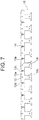
- Figure 6 is a plan that shows a state in which the segmented laminated cores 11 from Figure 4 are expanded rectilinearly.
- the first end portions and the second end portions of the back yoke portion 13a are configured such that predetermined gaps that connect the outer circumferential side to the inner circumferential side are formed between the adjacent projecting portions 13c and recess portions 13d when the core segments 13 are expanded rectilinearly such that the magnetic pole tooth portions 13b are parallel to each other.
- Figure 7 is a plan that shows a pressed state of a first core member 15 that is included in the segmented laminated cores 11 from Figure 6
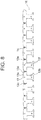
- Figure 8 is a plan that shows a pressed state of a second core member 16 that is included in the segmented laminated cores 11 from Figure 6
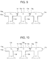
- Figure 9 is a plan that shows a portion of the first core member 15 from Figure 7 enlarged.
- first core members 15 that are formed by sequentially arranging core segments 13 in which the projecting portions 13c are oriented in a first direction relative to a direction of rotation of the rotary electric machine and second core members 16 that are formed by sequentially arranging core segments 13 in which the projecting portions 13c are oriented in a second direction relative to the direction of rotation of the rotary electric machine are stacked alternately and linked to each other.
- these first and second core members 15 and 16 are manufactured by pressing a magnetic material so as to be expanded rectilinearly such that the magnetic pole tooth portions 13b are parallel.
- two layers each of the first and second core members 15 and 16 are stacked alternately, and are linked in the direction of lamination by the punch-crimped portions 13f.
- dimensions of the gaps that connect the outer circumferential side of the back yoke portion 13a to the inner circumferential side are set to greater than or equal to a thickness dimension (approximately 0.5 mm, for example) of the core segments 13 (the magnetic material).
- notch portions 13g are disposed on the core segments 13, and the gaps 14 that connect from the outer circumferential side of the back yoke portions 13a to the inner circumferential side are formed between the adjacent projecting portions 13c and recess portions 13d when manufacturing the segmented laminated cores 11 that are expanded rectilinearly such that the respective magnetic pole tooth portions 13b are parallel, pressing of the segmented laminated cores 11 is made possible without using lancing methods, reducing machining strain, and enabling improvements in characteristics such as efficiency and torque pulsation to be achieved.
- the generation of scrap is also reduced, enabling productivity to be improved.
- the core segments 13 can be pressed in a rectilinearly arranged state on the electromagnetic steel sheet, material yield can be improved.
- the orientation of the core segments 13 on the electromagnetic steel sheet can be set to a constant direction, the influence of magnetic anisotropy in the electromagnetic steel sheet can be reduced compared to when pressed in a circular arc-shaped or annular state, enabling the torque pulsation to be reduced.
- the notch portions 13g are disposed in the recess portions 13d, but similar or identical effects can also be achieved if the notch portions 13g are disposed on the projecting portions 13c in the vicinity of the rotating shaft portions 13e.
- the laminated core 3 is configured by combining two segmented laminated cores 11, but the laminated core 3 may also be configured integrally without segmentation, or may also be configured by combining segmented laminated cores 11 that are divided into three or more segments.
- Figure 10 is a plan that shows part of a rotary electric machine laminated core according to Embodiment 2 of the present invention, and is a figure that corresponds to Figure 9 in Embodiment 1. Portions identical or equivalent to those in Embodiment 1 will be given identical numbering, and explanation thereof will be omitted.
- flat portions 13h that are perpendicular to magnetic pole tooth portions 13b are disposed on outer circumferential surfaces of back yoke portions 13a that are positioned radially outside a rotary electric machine.
- the flat portions 13h on each of the core segments 13 are disposed so as to be positioned collinearly in a state in which the segmented laminated cores 11 are expanded rectilinearly such that the magnetic pole tooth portions 13b are parallel, in other words, in the pressed state of the segmented laminated cores 11 in Embodiment 1.
- Figure 11 is a plan that shows part of a rotary electric machine laminated core according to Embodiment 3 of the present invention
- Figure 12 is a plan that shows a state in which segmented laminated cores 11 from Figure 11 are expanded rectilinearly, and are figures that correspond to Figure 5 and 9 , respectively, in Embodiment 1. Portions identical or equivalent to those in Embodiments 1 and 2 will be given identical numbering, and explanation thereof will be omitted.
- holding projecting portions 13i that come into contact with projecting portions 13c when core blocks 12 are closed into an annular shape or a circular arc shape are disposed on second end portions of back yoke portions 13a.
- the holding protruding portions 13i are disposed on outer circumferential end portions of notch portions 13g.
- the holding protruding portions 13i separate from the projecting portions 13c when the segmented laminated cores 11 are expanded rectilinearly (because the gaps between the projecting portions 13c and the holding protruding portions 13i are minute, the holding protruding portions 13i appear as if contacting the projecting portions 13c in Figure 12 ).
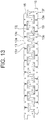
- Figure 13 is a plan that shows a state during assembly of a rotary electric machine laminated core according to Embodiment 4 of the present invention, and is a figure that corresponds to Figure 7 in Embodiment 1.
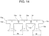
- Figure 14 is a plan that shows part of Figure 13 enlarged. Portions identical or equivalent to those in Embodiments 1, 2, and 3 will be given identical numbering, and explanation thereof will be omitted.
- width-reduced portions 13j in which width dimensions are smaller than in adjacent portions on an opposite side from back yoke portions 13a are disposed on magnetic pole tooth portions 13b in a vicinity of linking portions to the back yoke portions 13a.
- magnetic pole notch portions are disposed on two sides in a width direction of root portions of the magnetic pole tooth portions 13b.
- Two segmented laminated cores 11 can thereby be obtained during pressing by disposing the magnetic pole tooth portions 13b of one first core member 15 between the magnetic pole tooth portions 13b of another first core member 15.
- Bt is a width dimension at a tip end portion of the magnetic pole tooth portions 13b
- Bs is a width dimension between adjacent width-reduced portions 13j
- Bs > Bt.
- Bs so as to be greater than or equal to (Bt + 2T), where T is the sheet thickness of the core segments 13 (the magnetic material).
Landscapes
- Engineering & Computer Science (AREA)
- Power Engineering (AREA)
- Iron Core Of Rotating Electric Machines (AREA)
Claims (4)
- Laminierter Kern für elektrische Rotationsmaschine, der eine Vielzahl von Kernsegmenten (13) aufweist, die aufweisen:einen Hinterjochabschnitt (13a);einen Magnetpol-Zahnabschnitt (13b), der aus dem Hinterjochabschnitt (13a) nach außen vorsteht;einen vorstehenden Abschnitt (13c), der an einem ersten Endabschnitt des Hinterjochabschnittes (13a) angeordnet ist;einen Vertiefungsabschnitt (13d), der an einem zweiten Endabschnitt des Hinterjochabschnittes (13a) angeordnet ist; undwobei die Kernsegmente (13) in einer ringförmigen Form angeordnet sind und in einer axialen Richtung einer elektrischen Rotationsmaschine gestapelt sind, wobei:
einen Drehwellenabschnitt (13e), der an dem vorstehenden Abschnitt (13c) angeordnet ist,die vorstehenden Abschnitte (13c) gegen die Vertiefungsabschnitte (13d) von umfänglich benachbarten Kernsegmenten (13) anstoßen;ein erstes Kernglied (15), das durch sequentielles Anordnen der Kernsegmente (13) derart ausgebildet ist, dass die vorstehenden Abschnitte (13c) in einer ersten Richtung relativ zu einer Drehrichtung der elektrischen Rotationsmaschine orientiert sind, und ein zweites Kernglied (16), das durch sequentielles Anordnen der Kernelemente (13) derart ausgebildet ist, dass die vorstehenden Abschnitte (13c) in einer zweiten Richtung relativ zu der Drehrichtung der elektrischen Rotationsmaschine orientiert sind, abwechselnd gestapelt sind und miteinander verbunden sind;eine Vielzahl von Kernblöcken (12), die durch Stapeln der Kernsegmente (13) ausgebildet sind, so verbunden sind, dass sie wechselseitig um den Drehwellenabschnitt (13e) drehbar sind, unddie Drehwellenabschnitte (13e) näher zu einer äußeren Umfangsfläche als zu einer inneren Umfangsfläche der Hinterjochabschnitte (13a) angeordnet sind,wobei der laminierte Kern für eine elektrische Rotationsmaschine dadurch gekennzeichnet ist, dass:ein Einkerbungsabschnitt (13g) an einem Teil der vorstehenden Abschnitte (13c) oder der Vertiefungsabschnitte (13d) angeordnet ist, um so einen Spalt (14) an einem Teil zwischen einer Umgebung des Drehwellenabschnitts (13e) der vorstehenden Abschnitte (13c) und der Vertiefungsabschnitt (13d) zu bilden, wenn die Kernsegmente (13) in einer ringförmigen Form oder einer kreisförmigen Bogenform angeordnet sind;innere Umfangsseitenabschnitte der vorstehenden Abschnitte (13c) und die Vertiefungsabschnitte (13d) zwischen benachbarten Kernsegmenten einander in einem vorbestimmten Bereich berühren, wenn die Kernsegmente (13) in der ringförmigen Form oder der kreisförmigen Bogenform angeordnet sind;der erste Endabschnitt und der zweite Endabschnitt der Hinterjochabschnitte (13a) derart eingerichtet sind, dass ein vorbestimmter Spalt, der eine äußere Umfangsseite mit einer inneren Umfangsseite verbindet, zwischen benachbarten vorstehenden Abschnitten (13c) und Vertiefungsabschnitten (13d) ausgebildet wird, wenn sich die Kernsegmente (13) derart geradlinig entfalten, dass die Magnetpol-Zahnabschnitte (13b) parallel zueinander sind; undeine Abmessung des Spalts, der die äußere Umfangsseite mit der inneren Umfangsseite der Hinterjochabschnitte (13a) verbindet, größer oder gleich einer Dickenabmessung der Kernsegmente (13) ist. - Laminierter Kern für elektrische Rotationsmaschinen nach Anspruch 1, dadurch gekennzeichnet, dass ein flacher Abschnitt (13h), der senkrecht zu dem Magnetpol-Zahnabschnitt (13b) orientiert ist, auf einer äußeren Umfangsfläche des Hinterjochabschnittes (13a) angeordnet ist, der radial außerhalb der elektrischen Rotationsmaschine positioniert ist.
- Laminierter Kern für elektrische Rotationsmaschinen nach Anspruch 1, dadurch gekennzeichnet, dass ein Haltevorsprungsabschnitt (13i), der den vorstehenden Abschnitt (13c) berührt, wenn die Kernblöcke (12) in einer ringförmigen Form oder einer Kreisförmigen Bogenform geschlossen sind, an einem zweiten Endabschnitt des Hinterjochabschnittes (13a) angeordnet ist.
- Laminierter Kern für elektrische Rotationsmaschine nach Anspruch 1, dadurch gekennzeichnet, dass ein Abschnitt (13j) mit verringerter Breite, der eine Breitenabmessung aufweist, die kleiner als ein benachbarter Abschnitt auf einer gegenüberliegenden Seite des Hinterjochabschnittes (13a) ist, in einer Umgebung eines Verbindungsabschnittes zwischen dem Magnetpol-Zahnabschnitt (13b) und dem Hinterjochabschnitt (13a) angeordnet ist.
Applications Claiming Priority (1)
| Application Number | Priority Date | Filing Date | Title |
|---|---|---|---|
| PCT/JP2010/056365 WO2011125199A1 (ja) | 2010-04-08 | 2010-04-08 | 回転電機の積層鉄心 |
Publications (3)
| Publication Number | Publication Date |
|---|---|
| EP2557660A1 EP2557660A1 (de) | 2013-02-13 |
| EP2557660A4 EP2557660A4 (de) | 2016-12-07 |
| EP2557660B1 true EP2557660B1 (de) | 2019-03-06 |
Family
ID=44762185
Family Applications (1)
| Application Number | Title | Priority Date | Filing Date |
|---|---|---|---|
| EP10849442.8A Active EP2557660B1 (de) | 2010-04-08 | 2010-04-08 | Geschichteter eisenkern einer elektrischen drehmaschine |
Country Status (6)
| Country | Link |
|---|---|
| US (1) | US9136735B2 (de) |
| EP (1) | EP2557660B1 (de) |
| JP (1) | JP5579832B2 (de) |
| KR (1) | KR20120116985A (de) |
| CN (1) | CN102823112B (de) |
| WO (1) | WO2011125199A1 (de) |
Families Citing this family (18)
| Publication number | Priority date | Publication date | Assignee | Title |
|---|---|---|---|---|
| US9601950B2 (en) * | 2011-05-26 | 2017-03-21 | Mitsubishi Electric Corporation | Permanent magnet motor |
| CN103703655A (zh) * | 2011-10-06 | 2014-04-02 | 三菱电机株式会社 | 层叠铁心的制造方法以及使用该方法制造的层叠铁心 |
| FR2983656B1 (fr) * | 2011-12-05 | 2017-05-19 | Moteurs Leroy-Somer | Circuit magnetique en secteurs |
| JP5952701B2 (ja) * | 2012-10-04 | 2016-07-13 | ミネベア株式会社 | モータのステータ構造、ブラシレスモータ、およびモータのステータ構造の製造方法 |
| GB2511353B (en) * | 2013-03-01 | 2015-11-04 | Jaguar Land Rover Ltd | Electric machine having segmented stator with shield elements |
| GB2508022B (en) * | 2012-11-20 | 2015-07-15 | Jaguar Land Rover Ltd | Electric machine and method of operation thereof |
| EP2923431B1 (de) | 2012-11-20 | 2020-09-23 | Jaguar Land Rover Limited | Elektrische maschine und verfahren zu deren bedienung |
| US9960644B2 (en) | 2013-05-28 | 2018-05-01 | Mitsubishi Electric Corporation | Core for rotary electric machine |
| JP6091341B2 (ja) * | 2013-06-03 | 2017-03-08 | 三菱電機株式会社 | 分割電機子鉄心の製造装置及び電機子の製造方法並びに回転電機の製造方法 |
| KR101858888B1 (ko) * | 2014-03-26 | 2018-05-16 | 미쓰비시덴키 가부시키가이샤 | 회전 전기의 전기자 철심 및 회전 전기 |
| WO2015159389A1 (ja) * | 2014-04-16 | 2015-10-22 | 三菱電機株式会社 | 回転電機の電機子鉄心 |
| DE112015006823T5 (de) * | 2015-08-21 | 2018-05-09 | Mitsubishi Electric Corporation | Motor mit eingebetteten Permanentmagneten, Kompressor und Kühl- und Klimagerät |
| CN108702042B (zh) * | 2016-02-25 | 2020-10-23 | 株式会社安川电机 | 旋转电机和旋转电机的制造方法 |
| JP7028175B2 (ja) * | 2016-09-02 | 2022-03-02 | 日本電産株式会社 | ステータ、ステータの製造方法及びモータ |
| CN107707044A (zh) * | 2017-11-21 | 2018-02-16 | 浙江联宜电机有限公司 | 铰链式定子铁芯 |
| CN108110918A (zh) * | 2017-12-29 | 2018-06-01 | 台州市路桥鼎新阳光机电科技有限公司 | 一种电机定子冲片结构及其采用该冲片的定子 |
| ES2914811T3 (es) * | 2019-05-27 | 2022-06-16 | Magnax Bv | Estator para una máquina de flujo axial |
| CN111697717B (zh) * | 2020-06-30 | 2021-06-15 | 珠海凯邦电机制造有限公司 | 电机定子冲片及电机 |
Family Cites Families (25)
| Publication number | Priority date | Publication date | Assignee | Title |
|---|---|---|---|---|
| US4990809A (en) * | 1987-04-27 | 1991-02-05 | The Superior Electric Company | Variable reluctance motor |
| JP3430521B2 (ja) * | 1992-09-24 | 2003-07-28 | 松下電器産業株式会社 | 回転電機の固定子 |
| JP3568364B2 (ja) * | 1996-09-30 | 2004-09-22 | 松下電器産業株式会社 | 回転電機のコア |
| JPH11215744A (ja) | 1998-01-22 | 1999-08-06 | Matsushita Seiko Co Ltd | ブラシレスモータの固定子 |
| JP3279279B2 (ja) * | 1998-06-30 | 2002-04-30 | 三菱電機株式会社 | 鉄心装置 |
| JP2000069693A (ja) * | 1998-08-21 | 2000-03-03 | Matsushita Electric Ind Co Ltd | モータ |
| JP3609649B2 (ja) * | 1999-06-29 | 2005-01-12 | 三洋電機株式会社 | ブラシレスdcモータ及びこのモータを用いた冷媒圧縮機 |
| JP3623702B2 (ja) * | 1999-09-28 | 2005-02-23 | 山洋電気株式会社 | 回転電機用ステータ |
| JP3710706B2 (ja) | 2000-12-01 | 2005-10-26 | 三菱電機株式会社 | 積層コアの製造方法およびその製造に用いる金型装置 |
| JP4747423B2 (ja) * | 2001-03-02 | 2011-08-17 | パナソニック株式会社 | 電動機 |
| JP3786854B2 (ja) * | 2001-08-30 | 2006-06-14 | 株式会社三井ハイテック | 積層鉄心の製造方法 |
| US7111380B2 (en) * | 2002-10-31 | 2006-09-26 | Emerson Electric Co. | Method for forming an annular stator assembly |
| JP4057449B2 (ja) * | 2003-03-10 | 2008-03-05 | アスモ株式会社 | 回転電機のコア |
| JP4444639B2 (ja) * | 2003-05-08 | 2010-03-31 | アスモ株式会社 | 回転電機のステータ及びその製造方法 |
| US6946769B2 (en) | 2003-05-08 | 2005-09-20 | Asmo Co., Ltd. | Insulator and manufacturing method thereof, and stator for electric rotating machine |
| US7122933B2 (en) * | 2004-05-19 | 2006-10-17 | Emerson Electric Co. | Reduced coil segmented stator |
| JP2006081278A (ja) * | 2004-09-08 | 2006-03-23 | Asmo Co Ltd | ブラシレスモータ |
| JP4516463B2 (ja) | 2005-03-23 | 2010-08-04 | アスモ株式会社 | ブラシレスモータのステータ及びブラシレスモータ |
| JP2006304460A (ja) | 2005-04-19 | 2006-11-02 | Mitsubishi Electric Corp | 回転電機の固定子 |
| US7348706B2 (en) * | 2005-10-31 | 2008-03-25 | A. O. Smith Corporation | Stator assembly for an electric machine and method of manufacturing the same |
| JP4835168B2 (ja) * | 2006-01-25 | 2011-12-14 | 日本電産株式会社 | 電機子のコア、電機子、モータ、記録ディスク駆動装置およびコアプレートの製造方法 |
| JP5094257B2 (ja) | 2007-07-25 | 2012-12-12 | 三菱電機株式会社 | 回転電機の鉄心 |
| JP5171224B2 (ja) * | 2007-11-22 | 2013-03-27 | 三菱電機株式会社 | 回転電機 |
| JP4884418B2 (ja) | 2008-04-04 | 2012-02-29 | 三菱電機株式会社 | 分割固定子鉄心の製造方法 |
| JP5251384B2 (ja) | 2008-09-16 | 2013-07-31 | 三菱電機株式会社 | 積層コアおよびその製造方法 |
-
2010
- 2010-04-08 EP EP10849442.8A patent/EP2557660B1/de active Active
- 2010-04-08 WO PCT/JP2010/056365 patent/WO2011125199A1/ja active Application Filing
- 2010-04-08 KR KR1020127021325A patent/KR20120116985A/ko active Search and Examination
- 2010-04-08 CN CN201080065997.9A patent/CN102823112B/zh active Active
- 2010-04-08 JP JP2012509243A patent/JP5579832B2/ja active Active
- 2010-04-08 US US13/515,963 patent/US9136735B2/en active Active
Non-Patent Citations (1)
| Title |
|---|
| None * |
Also Published As
| Publication number | Publication date |
|---|---|
| KR20120116985A (ko) | 2012-10-23 |
| US9136735B2 (en) | 2015-09-15 |
| US20120248928A1 (en) | 2012-10-04 |
| EP2557660A4 (de) | 2016-12-07 |
| JP5579832B2 (ja) | 2014-08-27 |
| CN102823112A (zh) | 2012-12-12 |
| WO2011125199A1 (ja) | 2011-10-13 |
| CN102823112B (zh) | 2015-07-29 |
| JPWO2011125199A1 (ja) | 2013-07-08 |
| EP2557660A1 (de) | 2013-02-13 |
Similar Documents
| Publication | Publication Date | Title |
|---|---|---|
| EP2557660B1 (de) | Geschichteter eisenkern einer elektrischen drehmaschine | |
| EP2587632B1 (de) | Laminatkern für eine dynamoelektrische maschine | |
| EP2693605B1 (de) | Rotor und elektrischer rotationsmechanismus | |
| WO2013051125A1 (ja) | 積層鉄心の製造方法およびそれにより製造された積層鉄心 | |
| JP5859112B2 (ja) | 回転電機の電機子、及び回転電機の電機子の製造方法 | |
| JP6444497B2 (ja) | 回転電機およびその製造方法 | |
| JPWO2012095987A1 (ja) | 回転電機の積層鉄心及びその製造方法 | |
| JP2009100489A (ja) | スロットレス形回転電機 | |
| JP6076179B2 (ja) | 分割固定子鉄心とこの分割固定子鉄心を備えた固定子およびこの固定子を備えた回転電機ならびに分割固定子鉄心の製造方法 | |
| JP5376262B2 (ja) | 回転電機の固定子及びその製造方法 | |
| JP6045638B2 (ja) | 積層鉄心の製造方法 | |
| JP2016082839A (ja) | ブラシレスモータ | |
| WO2017090189A1 (ja) | 回転電機 | |
| JP3621894B2 (ja) | 内転型電動機の固定子 | |
| JP2005095000A (ja) | 内転型電動機の固定子 | |
| JP5256835B2 (ja) | 回転電機の固定子及び回転電機 | |
| JP4021433B2 (ja) | 内転型電動機の固定子 | |
| JP5835839B2 (ja) | ステータコア、モータ、及びステータコアの製造方法 | |
| JP7229402B2 (ja) | 電機子の製造方法、及び、電機子 | |
| JP5607591B2 (ja) | ステータ用外筒、ステータ、及びステータの製造方法 | |
| CN111864925B (zh) | 定子芯体的分割式芯体的制造方法及制造装置 | |
| JP2011160509A (ja) | ステータ | |
| JP2012125081A (ja) | 固定子鉄心および回転電機 | |
| JPWO2013051125A1 (ja) | 積層鉄心の製造方法およびそれにより製造された積層鉄心 | |
| JP2012213289A (ja) | ロータ及び回転電気機械 |
Legal Events
| Date | Code | Title | Description |
|---|---|---|---|
| PUAI | Public reference made under article 153(3) epc to a published international application that has entered the european phase |
Free format text: ORIGINAL CODE: 0009012 |
|
| 17P | Request for examination filed |
Effective date: 20120705 |
|
| AK | Designated contracting states |
Kind code of ref document: A1 Designated state(s): AT BE BG CH CY CZ DE DK EE ES FI FR GB GR HR HU IE IS IT LI LT LU LV MC MK MT NL NO PL PT RO SE SI SK SM TR |
|
| DAX | Request for extension of the european patent (deleted) | ||
| RA4 | Supplementary search report drawn up and despatched (corrected) |
Effective date: 20161107 |
|
| RIC1 | Information provided on ipc code assigned before grant |
Ipc: H02K 1/14 20060101ALI20161031BHEP Ipc: H02K 1/18 20060101AFI20161031BHEP |
|
| GRAP | Despatch of communication of intention to grant a patent |
Free format text: ORIGINAL CODE: EPIDOSNIGR1 |
|
| STAA | Information on the status of an ep patent application or granted ep patent |
Free format text: STATUS: GRANT OF PATENT IS INTENDED |
|
| INTG | Intention to grant announced |
Effective date: 20180928 |
|
| GRAS | Grant fee paid |
Free format text: ORIGINAL CODE: EPIDOSNIGR3 |
|
| GRAA | (expected) grant |
Free format text: ORIGINAL CODE: 0009210 |
|
| STAA | Information on the status of an ep patent application or granted ep patent |
Free format text: STATUS: THE PATENT HAS BEEN GRANTED |
|
| AK | Designated contracting states |
Kind code of ref document: B1 Designated state(s): AT BE BG CH CY CZ DE DK EE ES FI FR GB GR HR HU IE IS IT LI LT LU LV MC MK MT NL NO PL PT RO SE SI SK SM TR |
|
| REG | Reference to a national code |
Ref country code: GB Ref legal event code: FG4D |
|
| REG | Reference to a national code |
Ref country code: CH Ref legal event code: EP Ref country code: AT Ref legal event code: REF Ref document number: 1105867 Country of ref document: AT Kind code of ref document: T Effective date: 20190315 |
|
| REG | Reference to a national code |
Ref country code: DE Ref legal event code: R096 Ref document number: 602010057467 Country of ref document: DE |
|
| REG | Reference to a national code |
Ref country code: IE Ref legal event code: FG4D |
|
| REG | Reference to a national code |
Ref country code: NL Ref legal event code: MP Effective date: 20190306 |
|
| REG | Reference to a national code |
Ref country code: LT Ref legal event code: MG4D |
|
| PG25 | Lapsed in a contracting state [announced via postgrant information from national office to epo] |
Ref country code: SE Free format text: LAPSE BECAUSE OF FAILURE TO SUBMIT A TRANSLATION OF THE DESCRIPTION OR TO PAY THE FEE WITHIN THE PRESCRIBED TIME-LIMIT Effective date: 20190306 Ref country code: FI Free format text: LAPSE BECAUSE OF FAILURE TO SUBMIT A TRANSLATION OF THE DESCRIPTION OR TO PAY THE FEE WITHIN THE PRESCRIBED TIME-LIMIT Effective date: 20190306 Ref country code: NO Free format text: LAPSE BECAUSE OF FAILURE TO SUBMIT A TRANSLATION OF THE DESCRIPTION OR TO PAY THE FEE WITHIN THE PRESCRIBED TIME-LIMIT Effective date: 20190606 Ref country code: LT Free format text: LAPSE BECAUSE OF FAILURE TO SUBMIT A TRANSLATION OF THE DESCRIPTION OR TO PAY THE FEE WITHIN THE PRESCRIBED TIME-LIMIT Effective date: 20190306 |
|
| PG25 | Lapsed in a contracting state [announced via postgrant information from national office to epo] |
Ref country code: BG Free format text: LAPSE BECAUSE OF FAILURE TO SUBMIT A TRANSLATION OF THE DESCRIPTION OR TO PAY THE FEE WITHIN THE PRESCRIBED TIME-LIMIT Effective date: 20190606 Ref country code: GR Free format text: LAPSE BECAUSE OF FAILURE TO SUBMIT A TRANSLATION OF THE DESCRIPTION OR TO PAY THE FEE WITHIN THE PRESCRIBED TIME-LIMIT Effective date: 20190607 Ref country code: HR Free format text: LAPSE BECAUSE OF FAILURE TO SUBMIT A TRANSLATION OF THE DESCRIPTION OR TO PAY THE FEE WITHIN THE PRESCRIBED TIME-LIMIT Effective date: 20190306 Ref country code: LV Free format text: LAPSE BECAUSE OF FAILURE TO SUBMIT A TRANSLATION OF THE DESCRIPTION OR TO PAY THE FEE WITHIN THE PRESCRIBED TIME-LIMIT Effective date: 20190306 Ref country code: NL Free format text: LAPSE BECAUSE OF FAILURE TO SUBMIT A TRANSLATION OF THE DESCRIPTION OR TO PAY THE FEE WITHIN THE PRESCRIBED TIME-LIMIT Effective date: 20190306 |
|
| REG | Reference to a national code |
Ref country code: AT Ref legal event code: MK05 Ref document number: 1105867 Country of ref document: AT Kind code of ref document: T Effective date: 20190306 |
|
| PG25 | Lapsed in a contracting state [announced via postgrant information from national office to epo] |
Ref country code: IT Free format text: LAPSE BECAUSE OF FAILURE TO SUBMIT A TRANSLATION OF THE DESCRIPTION OR TO PAY THE FEE WITHIN THE PRESCRIBED TIME-LIMIT Effective date: 20190306 Ref country code: ES Free format text: LAPSE BECAUSE OF FAILURE TO SUBMIT A TRANSLATION OF THE DESCRIPTION OR TO PAY THE FEE WITHIN THE PRESCRIBED TIME-LIMIT Effective date: 20190306 Ref country code: RO Free format text: LAPSE BECAUSE OF FAILURE TO SUBMIT A TRANSLATION OF THE DESCRIPTION OR TO PAY THE FEE WITHIN THE PRESCRIBED TIME-LIMIT Effective date: 20190306 Ref country code: CZ Free format text: LAPSE BECAUSE OF FAILURE TO SUBMIT A TRANSLATION OF THE DESCRIPTION OR TO PAY THE FEE WITHIN THE PRESCRIBED TIME-LIMIT Effective date: 20190306 Ref country code: EE Free format text: LAPSE BECAUSE OF FAILURE TO SUBMIT A TRANSLATION OF THE DESCRIPTION OR TO PAY THE FEE WITHIN THE PRESCRIBED TIME-LIMIT Effective date: 20190306 Ref country code: PT Free format text: LAPSE BECAUSE OF FAILURE TO SUBMIT A TRANSLATION OF THE DESCRIPTION OR TO PAY THE FEE WITHIN THE PRESCRIBED TIME-LIMIT Effective date: 20190706 Ref country code: SK Free format text: LAPSE BECAUSE OF FAILURE TO SUBMIT A TRANSLATION OF THE DESCRIPTION OR TO PAY THE FEE WITHIN THE PRESCRIBED TIME-LIMIT Effective date: 20190306 |
|
| PG25 | Lapsed in a contracting state [announced via postgrant information from national office to epo] |
Ref country code: PL Free format text: LAPSE BECAUSE OF FAILURE TO SUBMIT A TRANSLATION OF THE DESCRIPTION OR TO PAY THE FEE WITHIN THE PRESCRIBED TIME-LIMIT Effective date: 20190306 Ref country code: SM Free format text: LAPSE BECAUSE OF FAILURE TO SUBMIT A TRANSLATION OF THE DESCRIPTION OR TO PAY THE FEE WITHIN THE PRESCRIBED TIME-LIMIT Effective date: 20190306 |
|
| REG | Reference to a national code |
Ref country code: CH Ref legal event code: PL |
|
| REG | Reference to a national code |
Ref country code: DE Ref legal event code: R097 Ref document number: 602010057467 Country of ref document: DE |
|
| REG | Reference to a national code |
Ref country code: BE Ref legal event code: MM Effective date: 20190430 |
|
| PG25 | Lapsed in a contracting state [announced via postgrant information from national office to epo] |
Ref country code: LU Free format text: LAPSE BECAUSE OF NON-PAYMENT OF DUE FEES Effective date: 20190408 Ref country code: AT Free format text: LAPSE BECAUSE OF FAILURE TO SUBMIT A TRANSLATION OF THE DESCRIPTION OR TO PAY THE FEE WITHIN THE PRESCRIBED TIME-LIMIT Effective date: 20190306 Ref country code: IS Free format text: LAPSE BECAUSE OF FAILURE TO SUBMIT A TRANSLATION OF THE DESCRIPTION OR TO PAY THE FEE WITHIN THE PRESCRIBED TIME-LIMIT Effective date: 20190706 |
|
| PLBE | No opposition filed within time limit |
Free format text: ORIGINAL CODE: 0009261 |
|
| STAA | Information on the status of an ep patent application or granted ep patent |
Free format text: STATUS: NO OPPOSITION FILED WITHIN TIME LIMIT |
|
| PG25 | Lapsed in a contracting state [announced via postgrant information from national office to epo] |
Ref country code: LI Free format text: LAPSE BECAUSE OF NON-PAYMENT OF DUE FEES Effective date: 20190430 Ref country code: CH Free format text: LAPSE BECAUSE OF NON-PAYMENT OF DUE FEES Effective date: 20190430 Ref country code: MC Free format text: LAPSE BECAUSE OF FAILURE TO SUBMIT A TRANSLATION OF THE DESCRIPTION OR TO PAY THE FEE WITHIN THE PRESCRIBED TIME-LIMIT Effective date: 20190306 Ref country code: DK Free format text: LAPSE BECAUSE OF FAILURE TO SUBMIT A TRANSLATION OF THE DESCRIPTION OR TO PAY THE FEE WITHIN THE PRESCRIBED TIME-LIMIT Effective date: 20190306 |
|
| 26N | No opposition filed |
Effective date: 20191209 |
|
| GBPC | Gb: european patent ceased through non-payment of renewal fee |
Effective date: 20190606 |
|
| PG25 | Lapsed in a contracting state [announced via postgrant information from national office to epo] |
Ref country code: SI Free format text: LAPSE BECAUSE OF FAILURE TO SUBMIT A TRANSLATION OF THE DESCRIPTION OR TO PAY THE FEE WITHIN THE PRESCRIBED TIME-LIMIT Effective date: 20190306 Ref country code: BE Free format text: LAPSE BECAUSE OF NON-PAYMENT OF DUE FEES Effective date: 20190430 |
|
| PG25 | Lapsed in a contracting state [announced via postgrant information from national office to epo] |
Ref country code: TR Free format text: LAPSE BECAUSE OF FAILURE TO SUBMIT A TRANSLATION OF THE DESCRIPTION OR TO PAY THE FEE WITHIN THE PRESCRIBED TIME-LIMIT Effective date: 20190306 |
|
| PG25 | Lapsed in a contracting state [announced via postgrant information from national office to epo] |
Ref country code: IE Free format text: LAPSE BECAUSE OF NON-PAYMENT OF DUE FEES Effective date: 20190408 Ref country code: GB Free format text: LAPSE BECAUSE OF NON-PAYMENT OF DUE FEES Effective date: 20190606 |
|
| PG25 | Lapsed in a contracting state [announced via postgrant information from national office to epo] |
Ref country code: FR Free format text: LAPSE BECAUSE OF NON-PAYMENT OF DUE FEES Effective date: 20190506 |
|
| PG25 | Lapsed in a contracting state [announced via postgrant information from national office to epo] |
Ref country code: CY Free format text: LAPSE BECAUSE OF FAILURE TO SUBMIT A TRANSLATION OF THE DESCRIPTION OR TO PAY THE FEE WITHIN THE PRESCRIBED TIME-LIMIT Effective date: 20190306 |
|
| PG25 | Lapsed in a contracting state [announced via postgrant information from national office to epo] |
Ref country code: HU Free format text: LAPSE BECAUSE OF FAILURE TO SUBMIT A TRANSLATION OF THE DESCRIPTION OR TO PAY THE FEE WITHIN THE PRESCRIBED TIME-LIMIT; INVALID AB INITIO Effective date: 20100408 Ref country code: MT Free format text: LAPSE BECAUSE OF FAILURE TO SUBMIT A TRANSLATION OF THE DESCRIPTION OR TO PAY THE FEE WITHIN THE PRESCRIBED TIME-LIMIT Effective date: 20190306 |
|
| REG | Reference to a national code |
Ref country code: DE Ref legal event code: R084 Ref document number: 602010057467 Country of ref document: DE |
|
| PG25 | Lapsed in a contracting state [announced via postgrant information from national office to epo] |
Ref country code: MK Free format text: LAPSE BECAUSE OF FAILURE TO SUBMIT A TRANSLATION OF THE DESCRIPTION OR TO PAY THE FEE WITHIN THE PRESCRIBED TIME-LIMIT Effective date: 20190306 |
|
| P01 | Opt-out of the competence of the unified patent court (upc) registered |
Effective date: 20230512 |
|
| PGFP | Annual fee paid to national office [announced via postgrant information from national office to epo] |
Ref country code: DE Payment date: 20230228 Year of fee payment: 14 |