EP2556397B1 - Méthode et dispositif pour modifier la caractéristique du faisceau optique d'un laser utilisant une fibre multi-gaines - Google Patents
Méthode et dispositif pour modifier la caractéristique du faisceau optique d'un laser utilisant une fibre multi-gaines Download PDFInfo
- Publication number
- EP2556397B1 EP2556397B1 EP11712871.0A EP11712871A EP2556397B1 EP 2556397 B1 EP2556397 B1 EP 2556397B1 EP 11712871 A EP11712871 A EP 11712871A EP 2556397 B1 EP2556397 B1 EP 2556397B1
- Authority
- EP
- European Patent Office
- Prior art keywords
- laser beam
- fibre
- core
- coupling
- fiber
- Prior art date
- Legal status (The legal status is an assumption and is not a legal conclusion. Google has not performed a legal analysis and makes no representation as to the accuracy of the status listed.)
- Active
Links
Images


Classifications
-
- H—ELECTRICITY
- H01—ELECTRIC ELEMENTS
- H01S—DEVICES USING THE PROCESS OF LIGHT AMPLIFICATION BY STIMULATED EMISSION OF RADIATION [LASER] TO AMPLIFY OR GENERATE LIGHT; DEVICES USING STIMULATED EMISSION OF ELECTROMAGNETIC RADIATION IN WAVE RANGES OTHER THAN OPTICAL
- H01S3/00—Lasers, i.e. devices using stimulated emission of electromagnetic radiation in the infrared, visible or ultraviolet wave range
- H01S3/10—Controlling the intensity, frequency, phase, polarisation or direction of the emitted radiation, e.g. switching, gating, modulating or demodulating
- H01S3/101—Lasers provided with means to change the location from which, or the direction in which, laser radiation is emitted
-
- B—PERFORMING OPERATIONS; TRANSPORTING
- B23—MACHINE TOOLS; METAL-WORKING NOT OTHERWISE PROVIDED FOR
- B23K—SOLDERING OR UNSOLDERING; WELDING; CLADDING OR PLATING BY SOLDERING OR WELDING; CUTTING BY APPLYING HEAT LOCALLY, e.g. FLAME CUTTING; WORKING BY LASER BEAM
- B23K26/00—Working by laser beam, e.g. welding, cutting or boring
- B23K26/02—Positioning or observing the workpiece, e.g. with respect to the point of impact; Aligning, aiming or focusing the laser beam
- B23K26/06—Shaping the laser beam, e.g. by masks or multi-focusing
- B23K26/064—Shaping the laser beam, e.g. by masks or multi-focusing by means of optical elements, e.g. lenses, mirrors or prisms
-
- B—PERFORMING OPERATIONS; TRANSPORTING
- B23—MACHINE TOOLS; METAL-WORKING NOT OTHERWISE PROVIDED FOR
- B23K—SOLDERING OR UNSOLDERING; WELDING; CLADDING OR PLATING BY SOLDERING OR WELDING; CUTTING BY APPLYING HEAT LOCALLY, e.g. FLAME CUTTING; WORKING BY LASER BEAM
- B23K26/00—Working by laser beam, e.g. welding, cutting or boring
- B23K26/02—Positioning or observing the workpiece, e.g. with respect to the point of impact; Aligning, aiming or focusing the laser beam
- B23K26/06—Shaping the laser beam, e.g. by masks or multi-focusing
- B23K26/067—Dividing the beam into multiple beams, e.g. multifocusing
-
- B—PERFORMING OPERATIONS; TRANSPORTING
- B23—MACHINE TOOLS; METAL-WORKING NOT OTHERWISE PROVIDED FOR
- B23K—SOLDERING OR UNSOLDERING; WELDING; CLADDING OR PLATING BY SOLDERING OR WELDING; CUTTING BY APPLYING HEAT LOCALLY, e.g. FLAME CUTTING; WORKING BY LASER BEAM
- B23K26/00—Working by laser beam, e.g. welding, cutting or boring
- B23K26/02—Positioning or observing the workpiece, e.g. with respect to the point of impact; Aligning, aiming or focusing the laser beam
- B23K26/06—Shaping the laser beam, e.g. by masks or multi-focusing
- B23K26/073—Shaping the laser spot
-
- G—PHYSICS
- G02—OPTICS
- G02B—OPTICAL ELEMENTS, SYSTEMS OR APPARATUS
- G02B6/00—Light guides; Structural details of arrangements comprising light guides and other optical elements, e.g. couplings
- G02B6/02—Optical fibres with cladding with or without a coating
- G02B6/02042—Multicore optical fibres
-
- G—PHYSICS
- G02—OPTICS
- G02B—OPTICAL ELEMENTS, SYSTEMS OR APPARATUS
- G02B6/00—Light guides; Structural details of arrangements comprising light guides and other optical elements, e.g. couplings
- G02B6/02—Optical fibres with cladding with or without a coating
- G02B6/036—Optical fibres with cladding with or without a coating core or cladding comprising multiple layers
- G02B6/03616—Optical fibres characterised both by the number of different refractive index layers around the central core segment, i.e. around the innermost high index core layer, and their relative refractive index difference
- G02B6/03638—Optical fibres characterised both by the number of different refractive index layers around the central core segment, i.e. around the innermost high index core layer, and their relative refractive index difference having 3 layers only
- G02B6/03644—Optical fibres characterised both by the number of different refractive index layers around the central core segment, i.e. around the innermost high index core layer, and their relative refractive index difference having 3 layers only arranged - + -
-
- G—PHYSICS
- G02—OPTICS
- G02B—OPTICAL ELEMENTS, SYSTEMS OR APPARATUS
- G02B6/00—Light guides; Structural details of arrangements comprising light guides and other optical elements, e.g. couplings
- G02B6/24—Coupling light guides
- G02B6/26—Optical coupling means
- G02B6/262—Optical details of coupling light into, or out of, or between fibre ends, e.g. special fibre end shapes or associated optical elements
-
- G—PHYSICS
- G02—OPTICS
- G02B—OPTICAL ELEMENTS, SYSTEMS OR APPARATUS
- G02B6/00—Light guides; Structural details of arrangements comprising light guides and other optical elements, e.g. couplings
- G02B6/24—Coupling light guides
- G02B6/26—Optical coupling means
- G02B6/28—Optical coupling means having data bus means, i.e. plural waveguides interconnected and providing an inherently bidirectional system by mixing and splitting signals
-
- G—PHYSICS
- G02—OPTICS
- G02B—OPTICAL ELEMENTS, SYSTEMS OR APPARATUS
- G02B6/00—Light guides; Structural details of arrangements comprising light guides and other optical elements, e.g. couplings
- G02B6/24—Coupling light guides
- G02B6/26—Optical coupling means
- G02B6/35—Optical coupling means having switching means
- G02B6/3502—Optical coupling means having switching means involving direct waveguide displacement, e.g. cantilever type waveguide displacement involving waveguide bending, or displacing an interposed waveguide between stationary waveguides
- G02B6/3508—Lateral or transverse displacement of the whole waveguides, e.g. by varying the distance between opposed waveguide ends, or by mutual lateral displacement of opposed waveguide ends
-
- G—PHYSICS
- G02—OPTICS
- G02B—OPTICAL ELEMENTS, SYSTEMS OR APPARATUS
- G02B6/00—Light guides; Structural details of arrangements comprising light guides and other optical elements, e.g. couplings
- G02B6/24—Coupling light guides
- G02B6/42—Coupling light guides with opto-electronic elements
-
- G—PHYSICS
- G02—OPTICS
- G02B—OPTICAL ELEMENTS, SYSTEMS OR APPARATUS
- G02B6/00—Light guides; Structural details of arrangements comprising light guides and other optical elements, e.g. couplings
- G02B6/24—Coupling light guides
- G02B6/42—Coupling light guides with opto-electronic elements
- G02B6/4201—Packages, e.g. shape, construction, internal or external details
- G02B6/4204—Packages, e.g. shape, construction, internal or external details the coupling comprising intermediate optical elements, e.g. lenses, holograms
- G02B6/4206—Optical features
-
- G—PHYSICS
- G02—OPTICS
- G02B—OPTICAL ELEMENTS, SYSTEMS OR APPARATUS
- G02B6/00—Light guides; Structural details of arrangements comprising light guides and other optical elements, e.g. couplings
- G02B6/24—Coupling light guides
- G02B6/42—Coupling light guides with opto-electronic elements
- G02B6/4296—Coupling light guides with opto-electronic elements coupling with sources of high radiant energy, e.g. high power lasers, high temperature light sources
-
- B—PERFORMING OPERATIONS; TRANSPORTING
- B23—MACHINE TOOLS; METAL-WORKING NOT OTHERWISE PROVIDED FOR
- B23K—SOLDERING OR UNSOLDERING; WELDING; CLADDING OR PLATING BY SOLDERING OR WELDING; CUTTING BY APPLYING HEAT LOCALLY, e.g. FLAME CUTTING; WORKING BY LASER BEAM
- B23K2103/00—Materials to be soldered, welded or cut
- B23K2103/02—Iron or ferrous alloys
- B23K2103/06—Cast-iron alloys
Definitions
- the invention relates to a method and an arrangement for generating a laser beam with different beam profile characteristics.
- a process or application change in a laser processing system is associated with a corresponding conversion effort that can range from a relatively simple replacement of individual optical components to the transition to another system.
- a method for achieving certain laser beam properties is known in which the laser beams of two laser beam sources are coupled at different coupling angles into a conventional optical fiber.
- beam shaping takes place as a function of the coupling angles of the two laser beams with different wavelengths, which are suitably selected for the respective biological or medical processing task.
- a single laser source can be used, whose wavelength can be switched.
- the coupling condition into the optical fiber depends essentially on the respective wavelength.
- the described method proves to be less than optimal for applications of a different nature because of disproportionate complexity and limited specialization in such cases.
- the proposed method limited to the wavelength-dependent beam shaping, which in turn leads to limitations for its applications.
- a light wave applicator for cutting and coagulating biological tissue by means of laser radiation which has a flexible optical fiber with a non-constant over its cross-section refractive index profile.
- the numerical aperture of the optical fiber can be varied in a targeted and reproducible manner by actuating a manipulator which is able to impart a curvature to the optical fiber in one of its subareas in such a way that a coupling of the laser light takes place over regions of different refractive indices of the optical fiber.
- Object of the present invention is therefore to provide a method for generating a laser beam with different laser beam profile characteristics, which allows using a plurality of laser beam sources or only a single laser beam source, in particular with a single wavelength, an application-specific change of the laser beam characteristic with relatively little effort, and an arrangement to provide.
- the aim is to simultaneously extend the spectrum of adaptation possibilities of beam profile characteristics to diverse applications as far as possible.
- a laser beam is coupled into the one fiber end of a Mehrfachclad fiber, in particular a Doppelclad fiber, and coupled out of the other fiber end of the Mehrfachclad fiber and for generating different beam profile characteristics of the coupled laser beam of the incident Laser beam is selectively coupled either at least in the inner fiber core of Mehrfachclad fiber or at least in at least one outer ring core of Mehrfachclad fiber.
- a multiple-clad fiber is understood as meaning a fiber having an inner fiber core and at least one outer toroidal core, for example a double-clad fiber having a single outer toroidal core or but also a tripleclad fiber with a further outer ring core following the first outer ring core.
- the incident laser beam is differently coupled into one or more of the cores of the multiple-clad fiber.
- a Doppelclad fiber with two cores has an inner fiber core and a cladding surrounding this fiber core as thin as possible and low refractive. This is followed by a single outer ring core, which is also surrounded by a low-breaking second cladding. It can be followed by another layer of glass, which defines the outer diameter of the fiber, but has no effect on their function in the sense of beam guidance. The conclusion is a coating of a plastic material, such as silicone and / or nylon, which serves to protect the fiber.
- a Doppelclad fiber depending on the coupling in the inner fiber core, in the outer ring core or both in the inner fiber core as well as in the outer ring core between different beam profile characteristics are selected at the fiber output.
- switching between these coupling variants makes it possible, for example, to choose between a comparatively good beam quality with a sharp focus, as required for a laser cutting process, and a "reduced” one, on the other hand. Beam quality with a "washed out” focus and with an almost uniform intensity distribution in the beam cross-section, which is particularly suitable for welding processes.
- the laser beam is coupled into the inner fiber core of the double clad fiber, which in this case behaves like a conventional standard fiber whose fiber core is surrounded by a low-breaking cladding. If, by contrast, a laser beam with a widened profile, for example uniform intensity, is required, then the laser beam is coupled into the outer ring core or both into the inner fiber core and into the outer ring core.
- a laser beam with a filled circular profile according to the inner fiber core, with a ring profile according to the outer ring core can thus be combined with a filled circular profile according to the two core regions at the output of the doubleclad fiber (with a narrow missing ring through the first cladding ) or obtained with the corresponding intermediates of said profile characteristics.
- each with different beam cross-sections, in particular each with different beam diameters, imaged on the coupling-side end face of the Doppelclad fiber can be achieved, for example, by means of an optical system which can be moved along the laser beam axis, such as e.g. a lens or aperture can be adjusted, which couples the laser beam either only in the inner fiber core or in the outer ring core or both in the inner fiber core as well as in the outer ring core depending on their traversing position.
- another beam cross-section or diameter may also be adjusted by using optics, such as optical fibers.
- a lens or aperture is selectively moved in or out of the beam path of the laser beam.
- the beam cross-section or diameter can be adapted to desired coupling conditions in the Doppelclad fiber by using a laser source with the optional guidance via optical waveguides of different beam guidance characteristics, as it can be adjusted over the diameter of the radiation-guiding optical waveguide.
- This principle of the choice of the coupling ratios in the Doppelclad fiber is also applicable to the use of the upstream optical waveguides associated laser beam sources, in particular laser beam sources of different beam qualities, transferable.
- Such coupled into the cladding radiation propagates at a great angle with respect to the fiber axis in the inner fiber core or outer ring core and exits at the fiber end also at great Win 'angle, which can heat up a subsequent optics.
- radiation located in the second cladding can destroy the coating of the fiber.
- modestripper can be used.
- the invention also relates, in a further aspect, to an arrangement suitable for carrying out the method described above, which according to the invention has a doubleclad fiber with an inner fiber core and at least one outer toroidal core and a switchable device with at least two switching positions in which the incident laser beam either is coupled at least in the inner fiber core of Doppelclad fiber or at least in the at least one outer ring core of Doppelclad fiber.
- the switchable device is deflected by an adjustable deflection optics in its at least two switching positions an incident laser beam in the direction transverse to the axis of the coupling-side end face of the Doppelclad fiber different distances, or by an adjusting device which in their at least two switching positions the coupling-side end face in the direction transverse to the incident laser beam moved differently far, formed.
- a deflecting optics means any adjustable optics which couple a laser beam into at least partially different fiber regions of the doubleclad fiber as a function of the adjustment position.
- the switchable device is formed by a movable optical system or aperture, which images in its at least two switching positions the incident laser beam, each with different beam cross-sections, in particular with different beam diameters, on the coupling-side end side of the Doppelclad fiber.
- the movable optics may include, for example, prisms, plane-parallel (glass) plates, collection and diverging lenses, mirrors, diffractive optical elements, etc. individually or in combinations.
- the optics is formed by a beam splitter, in particular by an optical wedge plate movable into the laser beam, for dividing the incident laser beam into at least two partial beams, which are respectively coupled into one of the cores of the double clad fiber.
- the division of the intensity between the inner fiber core and the outer ring core is dependent on how far the beam splitter engages in the beam path. This makes it possible to optimally adapt the intensity distribution and thus the beam profile of the decoupled laser beam to the respective application.
- the wedge plate can also be used as a beam splitter to couple the laser beam in its entirety either in the inner fiber core or in the outer ring core.
- a similar effect causes the movement / displacement of the coupling optics transversely to the optical axis of the laser beam.
- the coupling-in optical system is in the switchable states in each case in the beam path, wherein different beam deflections result depending on the position of the coupling-in optical system. Since in this case no beam splitting is performed and thus a division of the intensities can not take place via partial beams, it is preferred to deflect either into the inner fiber core or the outer ring core and to switch between at least two states representing these positions.
- the diameter of the inner fiber core of the double-clad fiber is preferably at most approximately 200 ⁇ m, in particular at most approximately 150 ⁇ m, preferably at most approximately 120 ⁇ m.
- a diameter of the inner fiber core of about 100 .mu.m one suitable for demanding laser applications, e.g. for laser cutting processes, to achieve good quality of the decoupled laser beam when coupled into the inner fiber core.
- the ring thickness of the at least one outer ring core of the doubleclad fiber is preferably chosen to be greater than or equal to the diameter of the inner fiber core.
- the outer ring diameter corresponds to that for certain applications, such. For laser welding, required wider laser beam profile and is application specific, for example, about 600 microns or 400 microns.
- the numerical aperture of the first cladding surrounding the inner fiber core is higher than the numerical aperture of the second cladding surrounding the at least one outer ring core.
- the first cladding has a standard numerical aperture of 0.22 (tolerance +/- 0.02), in which case the second cladding preferably has a numerical aperture of 0.18 (tolerance +/- 0.015) and should be sufficiently thick to guide the laser radiation well, for example, 10 microns thick, preferably less, such as 3 to 5 microns, with a core-to-shell ratio (CCDR) of 1.2.
- the first cladding forms a conventional transport fiber with the inner fiber core.
- the described embodiments using one or more laser beam sources can also be used in combination, for example within a cascaded system.
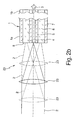
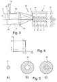
- FIGS. 1 to 3 show three different arrangements 10, 20, 30 for generating a laser beam with different beam profile characteristic, wherein the laser beam into the one fiber end 1a of a Mehrfachclad fiber 1, which is formed in the present case as Doppelclad fiber 1, coupled and from the other fiber end. 1 b of the double clad fiber 1 is decoupled.
- the incident laser beam is denoted by 2 and the decoupled laser beam is indicated schematically by 3 .
- the double-clad fiber 1 has an inner fiber core 4 (eg made of undoped quartz glass) with a refractive index n 1 and a thin first cladding 5 (eg made of doped quartz glass) surrounding the inner fiber core 4, whose refractive index n 2 is lower than n 1 .
- an outer ring core 6 eg made of undoped quartz glass
- the refractive index n 3 is likewise surrounded by a low-refractive second cladding 7 (for example made of doped quartz glass) with a refractive index n 4 .
- the refractive indices n 1 and n 3 may be the same or different; The same applies to the refractive indices n 2 and n 4 . It can be followed by another layer of glass (not shown), which defines the outer diameter of the fiber, but has no influence on their function in terms of beam guidance.
- the finish is typically a coating (not shown) of a plastic material, such as silicone and / or nylon, to protect the fiber.
- the incident on the coupling-side end face 8 of the Doppelclad fiber 1 laser beam 2 by means of a switchable device either in the inner fiber core 4 or in the outer ring core 6 or both in the inner fiber core 4 and the outer ring core 6 of the Doppelclad fiber 1 are coupled.
- the switchable device for selectively coupling the laser beam 2 is formed in the Doppelclad fiber 1 by an adjustable deflection optics 11 with two switching positions, which are shown in solid and dashed lines. In these two switching positions, the laser beam 2 focused on the coupling-in end face 8 is deflected differently in the direction 12 transversely to the axis of the coupling-in end face 8, in particular parallel-displaced to different extents. In one switch position, the laser beam 2 is eccentrically coupled eccentrically to the fiber axis only in the inner fiber core 4 and in the other switching position eccentrically to the fiber axis only in the outer ring core 6. In the first case, the decoupled laser beam 3, the in Fig.
- the decoupled laser beam 3 in the Fig. 5b shown wider beam profile, namely an outer ring core 6 corresponding annular profile 52, and a comparatively lower beam quality, as is desired in the material processing, for example, for a laser welding process.
- the decoupled laser beam 3 has a top hat ring beam profile, the quality of which is suitable for many applications.
- a deflection mirror can be used here. wherein the location of the coupling in the coupling-in end face of the double clad fiber 1 can be determined by the angular position of the deflection mirror or the deflection mirror can direct the radiation position dependent on different outputs, which in turn define different coupling regions.
- a partially transparent or only partially located in the beam path deflection mirror can also meet the described function of a beam splitter.
- the deflection optics 11 preferably include additional means for coupling the laser beam 2 into the coupling-in end face 8 of the double-clad fiber 1, such as a focusing lens, which may alternatively be arranged before or after the deflection optics 11.
- a sufficiently long Doppelclad fiber 1 allows even with eccentric coupling of the laser beam 2 to the fiber axis in the inner fiber core 4 or in the outer ring core 6 an angularly homogeneous intensity distribution in the decoupled laser beam.
- the switchable device for optional coupling of the laser beam 2 in the Doppelclad fiber 1 may also be formed by a motor-driven adjusting device 13 , for example, the transversely end face 8 of the Doppelclad fiber 1 in the direction 12 transversely to the incident laser beam 2 varies widely, causing the on the einkoppel broughte end face 8 focused laser beam 2 can be coupled either in the inner fiber core 4 or in the outer ring core 6.
- the switchable device for selectively coupling the laser beam 2 is formed in the Doppelclad fiber 1 by an adjustable telescope / expansion optics 21 shown here only schematically.
- the telescope / expansion optics 21 expands the incident laser beam 2 to respectively different beam diameters.
- the laser beam 2 is then imaged on the coupling-in end face 8 of the double-clad fiber 1 by a coupling-in optical system (eg lens) 22 , each having different beam diameters, in this case different focal diameters.
- a coupling-in optical system eg lens
- the laser beam 2 is centrally coupled, for example, in a switching position of the telescope / expansion optics 21 only in the inner fiber core 4 and coupled centrally in another switching position both in the inner fiber core 4 and in the outer ring core 6 ,
- the decoupled laser beam 3 has the beam profile 51 and in the second case the beam profile 53.
- the proportion of the coupled into the outer ring core 6 laser radiation and thus the power distribution to the inner fiber core 4 and the outer ring core 6, are continuously adjusted, whereby the beam profile of the decoupled laser beam 3 optimally adapted to the respective application can be.
- the switchable device for selectively coupling the laser beam 2 is formed in the Doppelclad fiber 1 by a focusing optics 23 shown here as a lens, which is displaceable along the laser beam axis in different switching positions, which are shown by solid, dashed and dash-dotted lines.
- the incident laser beam 2 is coupled by the focusing optics 23, each with different beam diameters, onto the coupling-in end face 8 of the double-clad fiber 1.
- the focused Laser beam 2 centrically coupled only in the inner fiber core 4; in the two other switching positions of the defocused laser beam 2 is coupled centrally both in the inner fiber core 4 and in the outer ring core 6.
- the decoupled laser beam 3 has the beam profile 51 and in the second case the beam profile 53.
- the arrangement shown 30 is the switchable device for selectively coupling the laser beam 2 in the Doppelclad fiber 1 formed by an example only as an optical wedge plate 31 beam splitter, which is continuously adjustable between two end positions, which are shown by solid and dashed lines.
- the optical wedge plate 31 In one end position, the optical wedge plate 31 is arranged outside the beam path of the incident laser beam 2, so that the entire incident laser beam 2 is coupled via an input optics (eg lens) 32 only in the inner fiber core 4, whereby the decoupled laser beam 3, the beam profile 51st having.
- the wedge plate 31 In its other end position shown in dashed lines, the wedge plate 31 is arranged in the entire beam path of the laser beam 2, so that the entire laser beam 2 is deflected by the wedge plate 31 and coupled via the coupling optics 32 only in the outer ring core 6, whereby the decoupled laser beam 3, the beam profile 52 has.
- a comparable effect causes the movement / displacement of the coupling optics 32 transversely to the optical axis of the laser beam 2.
- the coupling-in optical system 32 is located in the switchable states in each case in the beam path, 32 resulting in different beam deflections depending on the position of the coupling optics. Since in this case no beam splitting is carried out and thus a division of the intensities can not take place via partial beams, is preferably deflected either in the inner fiber core 4 or the outer ring core 6 and switched between at least two, these positions representing states.
- a partial introduction of the wedge plate 31 into the incident laser beam 2 leads to the formation of two partial beams 2a, 2b, so that here the optical wedge plate 31 serves as a beam splitter by way of example.
- the first partial beam 2a is not influenced by the wedge plate 31 and is therefore further coupled via the coupling optics 32 into the inner fiber core 4, while the second partial beam 2b is deflected by the wedge plate 31 relative to the first partial beam 2a and via the coupling optics 32 into the outer ring core 6 is coupled.
- the decoupled laser beam 3 has the beam profile 53.
- a partial introduction of the wedge plate 31 in the incident laser beam 2 thus leads to the formation of two partial beams 2a, 2b with a dependent on the degree of introduction division of the intensity between the inner fiber core 4 and the outer ring core 6, whereby the beam profile of the decoupled laser beam 3 optimally the respective application can be adapted.
- the two partial beams 2 a, 2 b offer the substantial advantage of eliminating the region of the first cladding 5 during coupling. It is important, in particular for applications in the high-power range, that no laser radiation is coupled into the inner or outer cladding 5, 7. This radiation propagates at a large angle in the inner core or outer ring core and also exits at the fiber end at a large angle, as a result of which the optics that follow can heat up. In addition, the radiation located in the outer cladding 7 can destroy the coating of the fiber 1.
- a diameter of the inner fiber core 4 of about 100 microns ensures in typical applications with high power in the kW range, the generation of a good beam profile quality when coupling the laser beam 2 in the inner fiber core 4.
- the first cladding 5 is already about 10 microns, preferably with about 5 microns, sufficiently thick to guide the laser radiation well.
Landscapes
- Physics & Mathematics (AREA)
- Optics & Photonics (AREA)
- General Physics & Mathematics (AREA)
- Engineering & Computer Science (AREA)
- Plasma & Fusion (AREA)
- Mechanical Engineering (AREA)
- Electromagnetism (AREA)
- Optical Couplings Of Light Guides (AREA)
- Laser Beam Processing (AREA)
Claims (14)
- Procédé pour générer un faisceau laser (3) présentant différentes caractéristiques de profil de faisceau,
lequel consiste
à coupler un faisceau laser (2) dans une extrémité de fibre (1a) d'une fibre à plusieurs gaines (1), en particulier d'une fibre à double gaine, et à le découpler de l'autre extrémité de fibre (1b) de la fibre à plusieurs gaines (1), et
pour générer différentes caractéristiques de profil de faisceau du faisceau laser découplé (3), à coupler le faisceau laser incident (2) au choix soit au moins dans le coeur de fibre interne (4) de la fibre à plusieurs gaines (1), soit au moins dans au moins un coeur annulaire externe (6) de la fibre à plusieurs gaines (1). - Procédé selon la revendication 1, caractérisé en ce que pour coupler au choix le faisceau laser (2) dans la fibre à plusieurs gaines (1), un mouvement relatif dans une direction (12) transversale au faisceau laser (2) est effectué entre le faisceau laser incident (2) et la face frontale côté couplage (8) de la fibre à plusieurs gaines (1).
- Procédé selon la revendication 1 ou la revendication 2, caractérisé en ce que pour coupler au choix le faisceau laser (2) dans la fibre à plusieurs gaines (1), le faisceau laser incident (2) est reproduit avec différentes sections transversales de faisceau, en particulier avec différents diamètres de faisceau, sur la face frontale côté couplage (8) de la fibre à plusieurs gaines (1).
- Procédé selon l'une des revendications précédentes, caractérisé en ce que pour coupler le faisceau laser (2) aussi bien dans le coeur de fibre interne (4) que dans ledit au moins un coeur annulaire externe (6), le faisceau laser incident (2) est divisé en au moins deux faisceaux partiels (2a, 2b) qui sont couplés chacun dans un des coeurs (4, 6) de la fibre à plusieurs gaines (1).
- Agencement (10 ; 20 ; 30) pour générer un faisceau laser (3) présentant différentes caractéristiques de profil de faisceau, avec :une fibre à plusieurs gaines (1), en particulier une fibre à double gaine, présentant un coeur de fibre interne (4) et au moins un coeur annulaire externe (6), ainsi que un dispositif commutable (11, 13 ; 21, 22 ; 23 ; 31, 32) présentant au moins deux position de commutation dans lesquelles un faisceau laser incident (2) est couplé au choix soit au moins dans le coeur de fibre interne (4) de la fibre à plusieurs gaines (1), soit au moins dans ledit au moins un coeur annulaire externe (6) de la fibre à plusieurs gaines (1).
- Agencement selon la revendication 5, caractérisé en ce que le dispositif commutable présente une optique de déviation réglable (11, 22, 31, 32) qui, dans ses au moins deux positions de commutation, dévie plus ou moins un faisceau laser incident (2) dans une direction (12) transversale à l'axe de la face frontale côté couplage (8), et/ou un dispositif de réglage (13) qui, dans ses au moins deux positions de commutation, déplace plus ou moins la face frontale côté couplage (8) de la fibre à plusieurs gaines (1) dans une direction (12) transversale au faisceau laser incident (2).
- Agencement selon la revendication 6, caractérisé en ce que l'optique de déviation présente un élément optique (22, 31, 32) positionnable dans au moins deux positions de commutation différentes transversalement à l'axe du laser.
- Agencement selon l'une des revendications 5 à 7, caractérisé en ce que le dispositif commutable présente une optique réglable (21 ; 23) ou un diaphragme qui, dans ses au moins deux positions de commutation, reproduit le faisceau laser incident (2) avec des sections transversales chaque fois différentes, en particulier avec des diamètres de faisceau chaque fois différents, sur la face frontale côté couplage (8) de la fibre à plusieurs gaines (1).
- Agencement selon la revendication 8, caractérisé en ce que l'optique réglable (23) peut aller et venir le long de l'axe du faisceau laser entre ses au moins deux positions de commutation.
- Agencement selon la revendication 7, caractérisé en ce que l'élément optique (31) ou un diaphragme est disposé à l'extérieur du chemin optique du faisceau laser (2) dans une position de commutation et au moins en partie dans le chemin optique du faisceau laser (2) dans au moins une autre position de commutation.
- Agencement selon la revendication 10, caractérisé en ce que l'élément optique est formé par un diviseur de faisceau, en particulier par une plaque optique cunéiforme (31) déplaçable dans le faisceau laser (2), pour diviser le faisceau laser incident (2) en au moins deux faisceaux partiels (2a, 2b), lesquels sont couplés chacun dans un des coeurs (4, 6) de la fibre à plusieurs gaines (1).
- Agencement selon l'une des revendications 5 à 11, caractérisé en ce que le diamètre (2 r 1) du coeur de fibre interne (4) de la fibre à plusieurs gaines (1) est au maximum d'environ 200 µm, en particulier au maximum d'environ 150 µm, de préférence au maximum d'environ 120 µm.
- Agencement selon l'une des revendications 5 à 12, caractérisé en ce que l'épaisseur d'anneau (r 3 - r 2) dudit au moins un coeur annulaire externe (6) de la fibre à plusieurs gaines (1) est supérieure ou égale au diamètre (2 r 1) du coeur de fibre interne (4).
- Agencement selon l'une des revendications 5 à 13, caractérisé en ce que dans la fibre à plusieurs gaines (1), l'ouverture numérique d'une première gaine (5) entourant le coeur de fibre interne (4) est supérieure à l'ouverture numérique d'une deuxième gaine (7) entourant ledit au moins un coeur annulaire externe (6).
Priority Applications (2)
| Application Number | Priority Date | Filing Date | Title |
|---|---|---|---|
| PL13165803T PL2624031T3 (pl) | 2010-04-08 | 2011-04-08 | Sposób i układ do generowania promienia laserowego o odmiennych charakterystykach profilu promienia za pomocą włókna wielowarstwowego |
| EP13165803.1A EP2624031B1 (fr) | 2010-04-08 | 2011-04-08 | Procédé et agencement pour générer un faisceau laser avec une caractéristique de profil de faisceau différente au moyen d'une fibre plusieurs fois chemisée |
Applications Claiming Priority (2)
| Application Number | Priority Date | Filing Date | Title |
|---|---|---|---|
| DE102010003750A DE102010003750A1 (de) | 2010-04-08 | 2010-04-08 | Verfahren und Anordnung zum Verändern der Strahlprofilcharakteristik eines Laserstrahls mittels einer Mehrfachclad-Faser |
| PCT/EP2011/055484 WO2011124671A1 (fr) | 2010-04-08 | 2011-04-08 | Procédé et système pour générer un faisceau laser présentant différentes caractéristiques de profil de faisceau au moyen d'une fibre à plusieurs gaines |
Related Child Applications (2)
| Application Number | Title | Priority Date | Filing Date |
|---|---|---|---|
| EP13165803.1A Division-Into EP2624031B1 (fr) | 2010-04-08 | 2011-04-08 | Procédé et agencement pour générer un faisceau laser avec une caractéristique de profil de faisceau différente au moyen d'une fibre plusieurs fois chemisée |
| EP13165803.1A Division EP2624031B1 (fr) | 2010-04-08 | 2011-04-08 | Procédé et agencement pour générer un faisceau laser avec une caractéristique de profil de faisceau différente au moyen d'une fibre plusieurs fois chemisée |
Publications (2)
| Publication Number | Publication Date |
|---|---|
| EP2556397A1 EP2556397A1 (fr) | 2013-02-13 |
| EP2556397B1 true EP2556397B1 (fr) | 2016-09-21 |
Family
ID=43875351
Family Applications (2)
| Application Number | Title | Priority Date | Filing Date |
|---|---|---|---|
| EP13165803.1A Active EP2624031B1 (fr) | 2010-04-08 | 2011-04-08 | Procédé et agencement pour générer un faisceau laser avec une caractéristique de profil de faisceau différente au moyen d'une fibre plusieurs fois chemisée |
| EP11712871.0A Active EP2556397B1 (fr) | 2010-04-08 | 2011-04-08 | Méthode et dispositif pour modifier la caractéristique du faisceau optique d'un laser utilisant une fibre multi-gaines |
Family Applications Before (1)
| Application Number | Title | Priority Date | Filing Date |
|---|---|---|---|
| EP13165803.1A Active EP2624031B1 (fr) | 2010-04-08 | 2011-04-08 | Procédé et agencement pour générer un faisceau laser avec une caractéristique de profil de faisceau différente au moyen d'une fibre plusieurs fois chemisée |
Country Status (7)
| Country | Link |
|---|---|
| US (6) | US8781269B2 (fr) |
| EP (2) | EP2624031B1 (fr) |
| KR (2) | KR101588544B1 (fr) |
| CN (2) | CN106918876B (fr) |
| DE (1) | DE102010003750A1 (fr) |
| PL (2) | PL2556397T3 (fr) |
| WO (1) | WO2011124671A1 (fr) |
Cited By (3)
| Publication number | Priority date | Publication date | Assignee | Title |
|---|---|---|---|---|
| DE102019218398A1 (de) * | 2019-11-27 | 2021-05-27 | Trumpf Laser- Und Systemtechnik Gmbh | Laserschweißen von Stromschienen mit Strahlformung |
| DE102021109622A1 (de) | 2021-04-16 | 2022-10-20 | Trumpf Laser- Und Systemtechnik Gmbh | Verfahren zum Verschweißen von metallhaltigen, gebogenen Stableitern, mit Intensitätsumverteilung in einer Anfangsphase und einer Endphase |
| WO2023061831A1 (fr) * | 2021-10-15 | 2023-04-20 | Trumpf Laser- Und Systemtechnik Gmbh | Procédé d'usinage laser d'une pièce présentant un écart d'intensité réduit |
Families Citing this family (139)
| Publication number | Priority date | Publication date | Assignee | Title |
|---|---|---|---|---|
| DE102010003750A1 (de) * | 2010-04-08 | 2011-10-13 | Trumpf Laser- Und Systemtechnik Gmbh | Verfahren und Anordnung zum Verändern der Strahlprofilcharakteristik eines Laserstrahls mittels einer Mehrfachclad-Faser |
| DE102011078173B4 (de) * | 2011-06-28 | 2020-06-18 | Trumpf Werkzeugmaschinen Gmbh + Co. Kg | Verfahren zum Laserschneiden eines mit einer Folie versehenen Werkstücks mittels zweier Laserstrahlen sowie dazugehörige Laserschneidmaschine |
| DE102011119319A1 (de) | 2011-11-24 | 2013-05-29 | Slm Solutions Gmbh | Optische Bestrahlungsvorrichtung für eine Anlage zur Herstellung von dreidimensionalen Werkstücken durch Bestrahlen von Pulverschichten eines Rohstoffpulvers mit Laserstrahlung |
| EP2788803B1 (fr) | 2011-12-09 | 2020-05-27 | Lumentum Operations LLC | Variation du produit des paramètres d'un faisceau laser |
| CN103246008A (zh) * | 2012-02-13 | 2013-08-14 | 无锡万润光子技术有限公司 | 基于阵列多芯的Airy光纤 |
| DE102012219074A1 (de) * | 2012-10-19 | 2014-04-24 | Trumpf Werkzeugmaschinen Gmbh + Co. Kg | Laserschneidmaschine und Verfahren zum Schneiden von Werkstücken unterschiedlicher Dicke |
| US11517978B2 (en) | 2012-10-19 | 2022-12-06 | Trumpf Werkzeugmaschinen Gmbh + Co. Kg | Laser cutting machine and method for cutting workpieces of different thicknesses |
| GB2510370A (en) | 2013-01-31 | 2014-08-06 | Gsi Group Ltd | Fibre Optical Laser Combiner |
| US10226837B2 (en) | 2013-03-15 | 2019-03-12 | Nlight, Inc. | Thermal processing with line beams |
| CN103252575B (zh) * | 2013-05-23 | 2016-06-08 | 纽敦光电科技(上海)有限公司 | 一种用于激光材料加工的光学传输方法及系统 |
| DE102013210857B3 (de) | 2013-06-11 | 2014-08-21 | Trumpf Werkzeugmaschinen Gmbh + Co. Kg | Verfahren zum Einstechen in metallische Werkstücke mittels eines Laserstrahls |
| US9458728B2 (en) | 2013-09-04 | 2016-10-04 | Siemens Energy, Inc. | Method for forming three-dimensional anchoring structures on a surface by propagating energy through a multi-core fiber |
| US10914902B2 (en) | 2014-02-26 | 2021-02-09 | TeraDiode, Inc. | Methods for altering properties of a radiation beam |
| US10069271B2 (en) | 2014-06-02 | 2018-09-04 | Nlight, Inc. | Scalable high power fiber laser |
| CN105720463B (zh) | 2014-08-01 | 2021-05-14 | 恩耐公司 | 光纤和光纤传输的激光器中的背向反射保护与监控 |
| EP3206830B1 (fr) | 2014-10-13 | 2019-08-07 | Trumpf Werkzeugmaschinen GmbH + Co. KG | Système optique muni d'un dispositif de couplage et d'un système de laser à fibre, ainsi que procédé d'usinage d'une pièce au moyen d'un tel système optique |
| US9837783B2 (en) | 2015-01-26 | 2017-12-05 | Nlight, Inc. | High-power, single-mode fiber sources |
| DE102015103127A1 (de) | 2015-03-04 | 2016-09-08 | Trumpf Laser- Und Systemtechnik Gmbh | Bestrahlungssystem für eine Vorrichtung zur generativen Fertigung |
| US10050404B2 (en) | 2015-03-26 | 2018-08-14 | Nlight, Inc. | Fiber source with cascaded gain stages and/or multimode delivery fiber with low splice loss |
| US9597749B2 (en) | 2015-05-26 | 2017-03-21 | Siemens Energy, Inc. | Laser waveguide with coaxial filler wire feed |
| EP3308202B1 (fr) | 2015-06-09 | 2021-09-08 | Corelase OY | Appareil et procédé de traitement au laser et composant optique destiné à ceux-ci |
| DE102015211403B4 (de) | 2015-06-22 | 2022-01-27 | Trumpf Werkzeugmaschinen Gmbh + Co. Kg | Verfahren zum Reduzieren von Ansatzmarken beim Laserschneiden von Werkstückteilen |
| WO2017008022A1 (fr) | 2015-07-08 | 2017-01-12 | Nlight, Inc. | Fibre dotée d'un indice central en creux destinée à un produit à paramètre augmenté |
| WO2017053985A1 (fr) | 2015-09-24 | 2017-03-30 | Nlight, Inc. | Contrôle du produit des paramètres de faisceau (bpp) en faisant varier un angle entre des fibres |
| US11179807B2 (en) | 2015-11-23 | 2021-11-23 | Nlight, Inc. | Fine-scale temporal control for laser material processing |
| CN108367389B (zh) | 2015-11-23 | 2020-07-28 | 恩耐公司 | 激光加工方法和装置 |
| US10466494B2 (en) * | 2015-12-18 | 2019-11-05 | Nlight, Inc. | Reverse interleaving for laser line generators |
| JP6662397B2 (ja) * | 2016-02-05 | 2020-03-11 | 村田機械株式会社 | レーザ加工機およびレーザ加工方法 |
| JP6796142B2 (ja) | 2016-04-06 | 2020-12-02 | テラダイオード, インコーポレーテッド | 可変レーザビームプロファイルのための光ファイバ構造および方法 |
| DE102016205930A1 (de) * | 2016-04-08 | 2017-10-12 | Siemens Aktiengesellschaft | Umschmelzen mit gleichzeitiger Erzeugung einer Druckringzone |
| US10598327B2 (en) * | 2016-04-27 | 2020-03-24 | Lumileds Llc | Laser-based light source |
| US9755739B1 (en) * | 2016-06-02 | 2017-09-05 | Google Inc. | WFOV and NFOV shared aperture beacon laser |
| JP6435290B2 (ja) | 2016-06-06 | 2018-12-05 | 株式会社フジクラ | 光学デバイス、レーザシステム及び光学デバイスの製造方法 |
| CN107848069B (zh) * | 2016-07-15 | 2019-10-08 | 可利雷斯股份有限公司 | 激光处理装置和方法 |
| DE102016118189B4 (de) | 2016-09-27 | 2018-08-30 | Trumpf Werkzeugmaschinen Gmbh + Co. Kg | Verfahren und Laserbearbeitungsmaschine zum Laserschweißen eines ersten und eines zweiten Werkstückabschnitts |
| US10739621B2 (en) * | 2016-09-29 | 2020-08-11 | Nlight, Inc. | Methods of and systems for materials processing using optical beams |
| US10690928B2 (en) * | 2016-09-29 | 2020-06-23 | Nlight, Inc. | Methods of and systems for heat deposition in additive manufacturing |
| US10673197B2 (en) | 2016-09-29 | 2020-06-02 | Nlight, Inc. | Fiber-based optical modulator |
| US10661342B2 (en) * | 2016-09-29 | 2020-05-26 | Nlight, Inc. | Additive manufacturing systems and methods for the same |
| US10730785B2 (en) | 2016-09-29 | 2020-08-04 | Nlight, Inc. | Optical fiber bending mechanisms |
| US10668567B2 (en) * | 2016-09-29 | 2020-06-02 | Nlight, Inc. | Multi-operation laser tooling for deposition and material processing operations |
| US10670872B2 (en) * | 2016-09-29 | 2020-06-02 | Nlight, Inc. | All-fiber optical beam switch |
| US10668535B2 (en) * | 2016-09-29 | 2020-06-02 | Nlight, Inc. | Method of forming three-dimensional objects |
| US10656440B2 (en) | 2016-09-29 | 2020-05-19 | Nlight, Inc. | Fiber optical beam delivery device producing output exhibiting intensity distribution profile having non-zero ellipticity |
| US10673199B2 (en) | 2016-09-29 | 2020-06-02 | Nlight, Inc. | Fiber-based saturable absorber |
| US10682726B2 (en) * | 2016-09-29 | 2020-06-16 | Nlight, Inc. | Beam modification structures and methods of modifying optical beam characteristics using the beam modification structures |
| US10684487B2 (en) * | 2016-09-29 | 2020-06-16 | Nlight, Inc. | Frequency-converted optical beams having adjustable beam characteristics |
| US10751834B2 (en) * | 2016-09-29 | 2020-08-25 | Nlight, Inc. | Optical beam delivery device formed of optical fibers configured for beam divergence or mode coupling control |
| US10705348B2 (en) * | 2016-09-29 | 2020-07-07 | Nlight, Inc. | Optical power density control in fiber-coupled laser |
| US10677984B2 (en) | 2016-09-29 | 2020-06-09 | Nlight, Inc. | Production of temporally apparent intensity distribution by rapid perturbation of variable beam characteristics optical fiber |
| US10673198B2 (en) | 2016-09-29 | 2020-06-02 | Nlight, Inc. | Fiber-coupled laser with time varying beam characteristics |
| US10656427B2 (en) * | 2016-09-29 | 2020-05-19 | Nlight, Inc. | Multicore fiber-coupled optical probing techniques |
| US10661391B2 (en) * | 2016-09-29 | 2020-05-26 | Nlight, Inc. | Method of forming pores in three-dimensional objects |
| US10663742B2 (en) * | 2016-09-29 | 2020-05-26 | Nlight, Inc. | Method and system for cutting a material using a laser having adjustable beam characteristics |
| US10668537B2 (en) * | 2016-09-29 | 2020-06-02 | Nlight, Inc. | Systems for and methods of temperature control in additive manufacturing |
| KR102498030B1 (ko) * | 2016-09-29 | 2023-02-08 | 엔라이트 인크. | 조정 가능한 빔 특성 |
| US10649241B2 (en) * | 2016-09-29 | 2020-05-12 | Nlight, Inc. | Multi-function semiconductor and electronics processing |
| US10663768B2 (en) * | 2016-09-29 | 2020-05-26 | Nlight, Inc. | Fiber optical beam delivery device producing selectable intensity profiles |
| US10646963B2 (en) * | 2016-09-29 | 2020-05-12 | Nlight, Inc. | Use of variable beam parameters to control a melt pool |
| US10732439B2 (en) | 2016-09-29 | 2020-08-04 | Nlight, Inc. | Fiber-coupled device for varying beam characteristics |
| US10224691B2 (en) | 2016-12-02 | 2019-03-05 | TeraDiode, Inc. | Laser systems utilizing fiber bundles for power delivery and beam switching |
| WO2018105453A1 (fr) * | 2016-12-06 | 2018-06-14 | パナソニックIpマネジメント株式会社 | Procédé d'alignement |
| JP6887502B2 (ja) * | 2016-12-08 | 2021-06-16 | コアレイズ オーワイ | レーザ加工装置および方法 |
| WO2018110016A1 (fr) * | 2016-12-12 | 2018-06-21 | パナソニックIpマネジメント株式会社 | Dispositif de couplage de fibres |
| WO2018140278A1 (fr) * | 2017-01-24 | 2018-08-02 | Corning Incorporated | Fibres optiques et systèmes optiques les comprenant |
| WO2018140543A1 (fr) * | 2017-01-26 | 2018-08-02 | TeraDiode, Inc. | Systèmes laser utilisant des fibres optiques à noyau cellulaire pour la mise en forme de faisceau |
| EP3412400A1 (fr) | 2017-06-09 | 2018-12-12 | Bystronic Laser AG | Conformateur de faisceau et son utilisation, dispositif de traitement par faisceau laser d'une pièce à usiner et son utilisation, procédé de traitement par faisceau laser d'une pièce à usiner |
| JP6419901B1 (ja) | 2017-06-20 | 2018-11-07 | 株式会社アマダホールディングス | レーザ加工機 |
| US10025052B1 (en) * | 2017-12-01 | 2018-07-17 | Shimadzu Corporation | Multiplexing laser light source and fiber adjustment method |
| JP2019101377A (ja) * | 2017-12-08 | 2019-06-24 | 株式会社島津製作所 | ファイバ出力型レーザ装置 |
| WO2019129917A1 (fr) * | 2017-12-29 | 2019-07-04 | Corelase Oy | Appareil et procédé de traitement au laser |
| EP3517241A1 (fr) | 2018-01-29 | 2019-07-31 | Bystronic Laser AG | Dispositif optique permettant de mettre en forme un faisceau d'ondes électromagnétiques et son utilisation, dispositif de traitement de faisceau et son utilisation et procédé de traitement de faisceau |
| GB201801560D0 (en) * | 2018-01-30 | 2018-03-14 | Spi Lasers Uk Ltd | Apparatus and method for controlling the spatial beam profile of laser radiation |
| WO2019240064A1 (fr) * | 2018-06-13 | 2019-12-19 | 古河電気工業株式会社 | Convertisseur de profil de faisceau, dispositif cathéter, et dispositif de cautérisation laser |
| CN108747053B (zh) * | 2018-07-13 | 2019-11-22 | 苏州福唐智能科技有限公司 | 一种自校准式激光切割设备 |
| CN112969943B (zh) * | 2018-11-12 | 2023-02-28 | 松下知识产权经营株式会社 | 用于光束成形的光学纤维结构和方法 |
| JP7186071B2 (ja) * | 2018-11-22 | 2022-12-08 | 株式会社アマダ | レーザ発振器及びレーザ加工機 |
| CN113169505A (zh) * | 2018-12-03 | 2021-07-23 | Ipg光子公司 | 具有可控输出光束强度分布曲线的超高光纤激光系统 |
| DE102018009524A1 (de) * | 2018-12-04 | 2020-06-04 | Lessmüller Lasertechnik GmbH | Verfahren und Vorrichtung zum Durchführen und Überwachen eines Bearbeitungsprozesses eines ersten Werkstücks und eines zweiten Werkstücks mittels eines hochenergetischen Bearbeitungsstrahls |
| IT201800021538A1 (it) * | 2018-12-31 | 2020-07-01 | Prima Electro S P A | Apparato per combinazione di fasci laser in fibre ottiche e procedimento corrispondente |
| CN109732796A (zh) * | 2019-01-30 | 2019-05-10 | 无锡中环应用材料有限公司 | 一种单晶硅片的切割方法 |
| EP3924136B1 (fr) | 2019-02-13 | 2023-04-26 | Coherent, Inc. | Procédé de soudage laser |
| CN113891777A (zh) * | 2019-03-28 | 2022-01-04 | 松下知识产权经营株式会社 | 利用高频光束整形的材料加工 |
| KR102279322B1 (ko) * | 2019-04-08 | 2021-07-21 | 한양대학교 산학협력단 | 다중 진단 및 치료 카테터와 이를 포함하는 카테터 시스템 |
| WO2020241136A1 (fr) | 2019-05-29 | 2020-12-03 | パナソニックIpマネジメント株式会社 | Dispositif d'usinage laser et procédé d'usinage laser faisant appel audit dispositif |
| WO2020241137A1 (fr) | 2019-05-29 | 2020-12-03 | パナソニックIpマネジメント株式会社 | Dispositif d'usinage au laser et procédé d'usinage au laser utilisant celui-ci |
| JP7382554B2 (ja) * | 2019-05-29 | 2023-11-17 | パナソニックIpマネジメント株式会社 | レーザ加工装置及びそれを用いたレーザ加工方法 |
| JP6764976B1 (ja) | 2019-06-06 | 2020-10-07 | 株式会社アマダ | レーザ加工機およびレーザ加工方法 |
| JP7333206B2 (ja) * | 2019-06-07 | 2023-08-24 | 京セラ株式会社 | 光学素子及び光伝送システム |
| DE102019115554A1 (de) | 2019-06-07 | 2020-12-10 | Bystronic Laser Ag | Bearbeitungsvorrichtung zur Laserbearbeitung eines Werkstücks und Verfahren zur Laserbearbeitung eines Werkstücks |
| DE102019210019B4 (de) | 2019-07-08 | 2021-06-10 | Trumpf Laser- Und Systemtechnik Gmbh | Optische Apparatur zum Laserschweißen eines Werkstücks, Verfahren zum Laserschweißen eines Werkstücks mittels mehrerer Teilstrahlen sowie Verwendung einer optischen Apparatur zum Laserschweißen |
| CN110320593B (zh) * | 2019-07-12 | 2020-06-23 | 武汉锐科光纤激光技术股份有限公司 | 一种光纤激光耦合器 |
| CN110412769B (zh) * | 2019-07-12 | 2020-06-23 | 武汉锐科光纤激光技术股份有限公司 | 一种光纤激光合束器 |
| US11583955B2 (en) * | 2019-08-06 | 2023-02-21 | Advalue Photonics, Inc. | Laser welding utilizing broadband pulsed laser sources |
| DE102019122064A1 (de) | 2019-08-16 | 2021-02-18 | Bystronic Laser Ag | Bearbeitungsvorrichtung zur Laserbearbeitung eines Werkstücks, Teilesatz für eine Bearbeitungsvorrichtung zur Laserbearbeitung eines Werkstücks und Verfahren zur Laserbearbeitung eines Werkstücks |
| DE102019212360A1 (de) | 2019-08-19 | 2021-02-25 | Trumpf Werkzeugmaschinen Gmbh + Co. Kg | Verfahren zum Brennschneiden mittels eines Laserstrahls |
| DE102019212403B4 (de) * | 2019-08-20 | 2022-04-07 | Trumpf Laser- Und Systemtechnik Gmbh | Verfahren zur Regelung mindestens eines Bearbeitungsparameters anhand mindestens eines Spritzermerkmals sowie zugehörige Bearbeitungsmaschine und Computerprogrammprodukt |
| JP7090056B2 (ja) * | 2019-09-06 | 2022-06-23 | 株式会社フジクラ | 光ファイバ、レーザ生成装置、レーザ加工装置、及び光ファイバの製造方法 |
| DE102019125103A1 (de) * | 2019-09-18 | 2021-03-18 | Bystronic Laser Ag | Bearbeitungsvorrichtung zur Laserbearbeitung eines Werkstücks, Verfahren zur Laserbearbeitung eines Werkstücks |
| DE102019215968A1 (de) | 2019-10-17 | 2021-04-22 | Trumpf Laser- Und Systemtechnik Gmbh | Laserschweißverfahren für Eckverbindungen von Werkstückteilen |
| DE102019217754A1 (de) * | 2019-11-18 | 2021-05-20 | Trumpf Laser- Und Systemtechnik Gmbh | Verfahren zum Laserschweißen eines Werkstücks, mit Strahlformung mittels eines Axicons, und optische Apparatur |
| JP2021086838A (ja) * | 2019-11-25 | 2021-06-03 | 株式会社フジクラ | レーザ装置 |
| JPWO2021111614A1 (fr) * | 2019-12-06 | 2021-06-10 | ||
| JP2021096370A (ja) * | 2019-12-17 | 2021-06-24 | 株式会社フジクラ | ビーム品質制御装置、及びこれを用いるレーザ装置 |
| WO2021125162A1 (fr) * | 2019-12-17 | 2021-06-24 | 株式会社フジクラ | Dispositif de commande de qualité de faisceau et dispositif laser le comprenant |
| DE102020200798A1 (de) | 2020-01-23 | 2021-07-29 | Trumpf Werkzeugmaschinen Gmbh + Co. Kg | Verfahren und Vorrichtung zur Lasermaterialbearbeitung mittels eines in seinem Leistungsprofil verstellbaren Bearbeitungslaserstrahls |
| DE102020201950B4 (de) | 2020-02-17 | 2023-09-21 | Trumpf Laser Gmbh | Laserlöten zum Verbinden von Elektronikbauteilen |
| DE102020105505A1 (de) | 2020-03-02 | 2021-09-02 | Trumpf Laser- Und Systemtechnik Gmbh | Verfahren zum Laserschweißen zweier beschichteter Werkstücke |
| JP2023058760A (ja) * | 2020-03-26 | 2023-04-26 | パナソニックIpマネジメント株式会社 | 光学装置、レーザ光出力システム、及びレーザ加工機 |
| CN111404611B (zh) * | 2020-04-01 | 2021-07-06 | 南京信息工程大学 | 双信号传输光纤及应用该光纤的传输装置和方法 |
| CN113649690A (zh) * | 2020-05-12 | 2021-11-16 | 深圳市联赢激光股份有限公司 | 一种具有圆形和环形光斑切变功能的光学系统 |
| DE102020205948A1 (de) | 2020-05-12 | 2021-11-18 | Trumpf Laser- Und Systemtechnik Gmbh | Laserschneidverfahren und Laserschneidanlage |
| CN113649689A (zh) * | 2020-05-12 | 2021-11-16 | 深圳市联赢激光股份有限公司 | 一种光学系统 |
| US11524361B2 (en) | 2020-05-22 | 2022-12-13 | Coherent, Inc. | Laser welding method |
| WO2021241545A1 (fr) * | 2020-05-26 | 2021-12-02 | 株式会社フジクラ | Combinateur optique et dispositif laser |
| DE102020116268A1 (de) * | 2020-06-19 | 2021-12-23 | Ii-Vi Delaware, Inc. | Fasergekoppelter laser mit variablem strahlparameterprodukt |
| DE112021003639T5 (de) * | 2020-07-07 | 2023-06-15 | Panasonic Intellectual Property Management Co., Ltd. | Stufen-kern-faserstrukturen und verfahren zur veränderung von strahlform und intensität |
| WO2022013144A1 (fr) * | 2020-07-14 | 2022-01-20 | El.En. S.P.A. | Équipement laser doté d'une source laser et d'un déflecteur de faisceau |
| DE102020128186A1 (de) | 2020-10-27 | 2022-04-28 | Trumpf Werkzeugmaschinen Gmbh + Co. Kg | Verfahren und Vorrichtung zum Laserschneiden mittels eines in einer Multikernfaser geführten Laserstrahls sowie zugehöriges Computerprogrammprodukt |
| CN112531452A (zh) * | 2020-11-11 | 2021-03-19 | 武汉锐科光纤激光技术股份有限公司 | 激光光束调节器件 |
| EP4056309A1 (fr) | 2021-03-09 | 2022-09-14 | Bystronic Laser AG | Dispositif et procédé de découpe laser d'une pièce et production de pièces |
| DE102021113834A1 (de) * | 2021-05-28 | 2022-12-01 | Trumpf Laser- Und Systemtechnik Gmbh | Bipolarplatte für eine Brennstoffzelle und Verfahren zum Schweißen einer Bipolarplatte |
| DE102021206488A1 (de) | 2021-06-23 | 2022-12-29 | Trumpf Laser- Und Systemtechnik Gmbh | Verfahren zum mehrfachen Abfahren einer Schweißkontur mit mehreren Laserspots |
| DE102021206490A1 (de) | 2021-06-23 | 2022-12-29 | Trumpf Laser- Und Systemtechnik Gmbh | Verfahren und Vorrichtung zum Erzeugen einer Schweißkontur mit mehreren Laserspots über eine Scanneroptik |
| DE102021206486A1 (de) | 2021-06-23 | 2022-12-29 | Trumpf Laser- Und Systemtechnik Gmbh | Verfahren zum mediendichten Verschweißen von aluminiumhaltigen Bauteilen |
| DE102021118390A1 (de) | 2021-07-15 | 2023-01-19 | Trumpf Laser- Und Systemtechnik Gmbh | Schweißoptik zum Laserschweißen von Werkstücken, mit flexibler Einstellung von Anzahl und Abstand von Laserspots über Zylinderlinsen |
| US11693176B2 (en) * | 2021-09-30 | 2023-07-04 | Lumentum Operations Llc | In-fiber beam scanning |
| DE102021126749A1 (de) | 2021-10-15 | 2023-04-20 | Trumpf Laser- Und Systemtechnik Gmbh | Laserschweißverfahren |
| DE102021126754A1 (de) | 2021-10-15 | 2023-04-20 | Trumpf Laser- Und Systemtechnik Gmbh | Verfahren zum Laserschweißen eines Werkstücks mit schnellem Wechsel zwischen Schweißzonen mit unterschiedlichen zu schweißenden Materialien |
| DE102022101092A1 (de) | 2022-01-18 | 2023-07-20 | Trumpf Laser- Und Systemtechnik Gmbh | Verfahren zur Laserbearbeitung eines Werkstücks mit verringerter Intensitätslücke |
| DE102021126755A1 (de) | 2021-10-15 | 2023-04-20 | Trumpf Laser- Und Systemtechnik Gmbh | Verfahren zur Laserbearbeitung eines Werkstücks, mit verringerter Intensitätslücke |
| DE102021130289A1 (de) | 2021-11-19 | 2023-05-25 | Trumpf Laser- Und Systemtechnik Gmbh | Verfahren zum Laserauftragschweißen |
| CN114043092B (zh) * | 2021-12-10 | 2022-05-27 | 哈尔滨工业大学 | 一种点环激光与电弧复合焊接方法 |
| DE102022110078A1 (de) | 2022-04-26 | 2023-10-26 | Trumpf Laser Gmbh | Vorrichtung und Verfahren zur Modifikation des Strahlprofils eines Laserstrahls |
| DE102022112212A1 (de) | 2022-05-16 | 2023-11-16 | TRUMPF Werkzeugmaschinen SE + Co. KG | Technik zum Erzeugen einer Kantenverrundung |
| US20230402807A1 (en) * | 2022-06-10 | 2023-12-14 | Panasonic Intellectual Property Management Co., Ltd. | Fiber-coupled laser systems with controllable beam shapes |
| WO2024003551A1 (fr) | 2022-06-29 | 2024-01-04 | Trumpf Laser Uk Limited | Appareil de traitement au laser d'un matériau |
| DE102022119556A1 (de) | 2022-08-04 | 2024-02-15 | Trumpf Laser Gmbh | Vorrichtung und Verfahren zum Einkoppeln eines Laserstrahls in eine Doppelclad-Faser |
| WO2024069758A1 (fr) * | 2022-09-27 | 2024-04-04 | ファナック株式会社 | Dispositif d'usinage au laser et procédé d'usinage au laser |
Citations (1)
| Publication number | Priority date | Publication date | Assignee | Title |
|---|---|---|---|---|
| EP0362466A2 (fr) * | 1988-10-06 | 1990-04-11 | Messerschmitt-Bölkow-Blohm Gesellschaft mit beschränkter Haftung | Dispositf de guides d'ondes lumineuses et d'irradiation |
Family Cites Families (43)
| Publication number | Priority date | Publication date | Assignee | Title |
|---|---|---|---|---|
| US3941670A (en) * | 1970-11-12 | 1976-03-02 | Massachusetts Institute Of Technology | Method of altering biological and chemical activity of molecular species |
| DE2443128A1 (de) * | 1974-09-09 | 1976-03-25 | Siemens Ag | Laserstrahl-koppelanordnung |
| FR2284892A1 (fr) * | 1974-09-13 | 1976-04-09 | Thomson Csf | Coupleur variable pour fibres optiques |
| IT1170643B (it) * | 1981-01-22 | 1987-06-03 | Selenia Ind Elettroniche | Dispositivo perfezionato per l'accoppiamento di un fascio laser ad una fibra ottica |
| US4575181A (en) * | 1983-04-26 | 1986-03-11 | Tokyo Shibaura Denki Kabushiki Kaisha | Optical fiber assembly with cladding light scattering means |
| DE3833992A1 (de) | 1988-10-06 | 1990-04-12 | Messerschmitt Boelkow Blohm | Bestrahlungseinrichtung |
| DE4200587C1 (en) * | 1992-01-11 | 1993-04-01 | Schott Glaswerke, 6500 Mainz, De | Light wave applicator for cutting and coagulating biological tissue - applies laser beam via flexible optical fibre having non-constant refractive index profile along its cross=section |
| JPH05298419A (ja) | 1992-04-20 | 1993-11-12 | Ricoh Co Ltd | 画像ファイリング装置 |
| RU2111520C1 (ru) * | 1993-07-21 | 1998-05-20 | Фирма "Самсунг Электроникс Ко., Лтд." | Оптический процессор с бустерным выходом |
| US5461692A (en) | 1993-11-30 | 1995-10-24 | Amoco Corporation | Multimode optical fiber coupling apparatus and method of transmitting laser radiation using same |
| JP3531199B2 (ja) * | 1994-02-22 | 2004-05-24 | 三菱電機株式会社 | 光伝送装置 |
| WO2001042819A2 (fr) * | 1999-12-08 | 2001-06-14 | Optigain, Inc. | Fibre optique a gaines multiples et amplificateur |
| US20020168139A1 (en) * | 2001-03-30 | 2002-11-14 | Clarkson William Andrew | Optical fiber terminations, optical couplers and optical coupling methods |
| US6563995B2 (en) * | 2001-04-02 | 2003-05-13 | Lightwave Electronics | Optical wavelength filtering apparatus with depressed-index claddings |
| US6819815B1 (en) * | 2001-12-12 | 2004-11-16 | Calient Networks | Method and apparatus for indirect adjustment of optical switch reflectors |
| JP4316840B2 (ja) * | 2002-06-21 | 2009-08-19 | 浜松ホトニクス株式会社 | ファイバレーザ装置 |
| US7245802B2 (en) * | 2003-08-04 | 2007-07-17 | Semiconductor Energy Laboratory Co., Ltd. | Beam homogenizer, laser irradiation apparatus and method for manufacturing semiconductor device |
| GB0328370D0 (en) | 2003-12-05 | 2004-01-14 | Southampton Photonics Ltd | Apparatus for providing optical radiation |
| JP4354338B2 (ja) * | 2004-06-07 | 2009-10-28 | タイコエレクトロニクスアンプ株式会社 | 多心光コネクタ組立体 |
| JP4995720B2 (ja) * | 2004-07-02 | 2012-08-08 | ザ ジェネラル ホスピタル コーポレイション | ダブルクラッドファイバを有する内視鏡撮像プローブ |
| US7412135B2 (en) * | 2005-01-21 | 2008-08-12 | Nufern | Fiber optic coupler, optical fiber useful with the coupler and/or a pump light source, and methods of coupling light |
| US7787729B2 (en) * | 2005-05-20 | 2010-08-31 | Imra America, Inc. | Single mode propagation in fibers and rods with large leakage channels |
| US7391561B2 (en) * | 2005-07-29 | 2008-06-24 | Aculight Corporation | Fiber- or rod-based optical source featuring a large-core, rare-earth-doped photonic-crystal device for generation of high-power pulsed radiation and method |
| CA2535472C (fr) * | 2006-02-07 | 2014-04-22 | Itf Technologies Optiques Inc./Itf Optical Technologies Inc. | Coupleur de revetement exterieur de fibres multimode pour fibres a multirevetements |
| KR100750511B1 (ko) | 2006-05-29 | 2007-08-20 | 주식회사 뉴하트바이오 | 나노 웹과 pdms 레이어를 이용한 인공 신장 칩 |
| JP4784406B2 (ja) | 2006-06-13 | 2011-10-05 | 住友電気工業株式会社 | ファイバレーザ装置およびレーザ加工方法 |
| GB2439345A (en) * | 2006-06-23 | 2007-12-27 | Gsi Group Ltd | Annular tapered fibre coupler for cladding pumping of an optical fibre |
| GB2444091A (en) * | 2006-11-24 | 2008-05-28 | Gsi Group Ltd | A Laser Amplifier |
| WO2007148127A2 (fr) * | 2006-06-23 | 2007-12-27 | Gsi Group Limited | Système laser à fibre |
| US7738166B2 (en) * | 2006-11-21 | 2010-06-15 | Pyrophotonics Lasers, Inc. | Fiber amplifier with integrated fiber laser pump |
| EP1935498A1 (fr) * | 2006-12-22 | 2008-06-25 | Universität Leipzig | Dispositif et procédé destinés à la manipulation et à l'alignement sans contact de petites parties d'échantillons dans un volume de mesure à l'aide d'un champ électrique alternatif non homogène |
| GB2449689B (en) * | 2007-05-31 | 2010-04-28 | Fujitsu Ltd | A method and apparatus relating to optical fibres |
| WO2009155536A2 (fr) | 2008-06-20 | 2009-12-23 | The General Hospital Corporation | Coupleur fondu de fibres optiques et procédé associé |
| EP2344916A4 (fr) | 2008-07-14 | 2014-12-31 | Chiral Photonics Inc | Réseau de coupleurs de fibres optiques |
| EP2456592B1 (fr) * | 2009-07-20 | 2013-04-03 | Precitec KG | Tête d'usinage au laser et procédé permettant de compenser la variation de position du foyer pour une tête d'usinage au laser |
| EP2335848B1 (fr) * | 2009-12-04 | 2014-08-20 | SLM Solutions GmbH | Unité de rayonnement optique pour une installation destinée à la fabrication de pièces à usiner par rayonnement de couches de pulvérisation avec un rayonnement laser |
| DE102010003750A1 (de) * | 2010-04-08 | 2011-10-13 | Trumpf Laser- Und Systemtechnik Gmbh | Verfahren und Anordnung zum Verändern der Strahlprofilcharakteristik eines Laserstrahls mittels einer Mehrfachclad-Faser |
| US8254417B2 (en) * | 2010-06-14 | 2012-08-28 | Ipg Photonics Corporation | Fiber laser system with controllably alignable optical components thereof |
| DE102012219074A1 (de) * | 2012-10-19 | 2014-04-24 | Trumpf Werkzeugmaschinen Gmbh + Co. Kg | Laserschneidmaschine und Verfahren zum Schneiden von Werkstücken unterschiedlicher Dicke |
| US9366887B2 (en) * | 2014-02-26 | 2016-06-14 | TeraDiode, Inc. | Systems and methods for laser systems with variable beam parameter product utilizing thermo-optic effects |
| US9755739B1 (en) * | 2016-06-02 | 2017-09-05 | Google Inc. | WFOV and NFOV shared aperture beacon laser |
| CN107848069B (zh) * | 2016-07-15 | 2019-10-08 | 可利雷斯股份有限公司 | 激光处理装置和方法 |
| WO2018195510A1 (fr) * | 2017-04-21 | 2018-10-25 | Nuburu, Inc. | Fibre optique à gaine multiple |
-
2010
- 2010-04-08 DE DE102010003750A patent/DE102010003750A1/de not_active Withdrawn
-
2011
- 2011-04-08 EP EP13165803.1A patent/EP2624031B1/fr active Active
- 2011-04-08 PL PL11712871T patent/PL2556397T3/pl unknown
- 2011-04-08 CN CN201610848362.5A patent/CN106918876B/zh active Active
- 2011-04-08 KR KR1020147021038A patent/KR101588544B1/ko active IP Right Grant
- 2011-04-08 US US13/639,401 patent/US8781269B2/en active Active
- 2011-04-08 PL PL13165803T patent/PL2624031T3/pl unknown
- 2011-04-08 WO PCT/EP2011/055484 patent/WO2011124671A1/fr active Application Filing
- 2011-04-08 EP EP11712871.0A patent/EP2556397B1/fr active Active
- 2011-04-08 KR KR1020127029127A patent/KR101456768B1/ko active IP Right Grant
- 2011-04-08 CN CN201180028439.XA patent/CN103097931B/zh active Active
-
2014
- 2014-06-09 US US14/300,138 patent/US9482821B2/en active Active
-
2016
- 2016-09-29 US US15/279,781 patent/US10281656B2/en active Active
-
2019
- 2019-04-30 US US16/398,362 patent/US11215761B2/en active Active
-
2021
- 2021-12-16 US US17/552,455 patent/US11806804B2/en active Active
-
2023
- 2023-11-06 US US18/387,089 patent/US20240139866A1/en active Pending
Patent Citations (1)
| Publication number | Priority date | Publication date | Assignee | Title |
|---|---|---|---|---|
| EP0362466A2 (fr) * | 1988-10-06 | 1990-04-11 | Messerschmitt-Bölkow-Blohm Gesellschaft mit beschränkter Haftung | Dispositf de guides d'ondes lumineuses et d'irradiation |
Cited By (4)
| Publication number | Priority date | Publication date | Assignee | Title |
|---|---|---|---|---|
| DE102019218398A1 (de) * | 2019-11-27 | 2021-05-27 | Trumpf Laser- Und Systemtechnik Gmbh | Laserschweißen von Stromschienen mit Strahlformung |
| DE102021109622A1 (de) | 2021-04-16 | 2022-10-20 | Trumpf Laser- Und Systemtechnik Gmbh | Verfahren zum Verschweißen von metallhaltigen, gebogenen Stableitern, mit Intensitätsumverteilung in einer Anfangsphase und einer Endphase |
| DE102021109622B4 (de) | 2021-04-16 | 2023-12-21 | Trumpf Laser- Und Systemtechnik Gmbh | Verfahren zum Verschweißen von metallhaltigen, gebogenen Stableitern, mit Intensitätsumverteilung in einer Anfangsphase und einer Endphase und Verwendung von Stableiteranordnungen |
| WO2023061831A1 (fr) * | 2021-10-15 | 2023-04-20 | Trumpf Laser- Und Systemtechnik Gmbh | Procédé d'usinage laser d'une pièce présentant un écart d'intensité réduit |
Also Published As
| Publication number | Publication date |
|---|---|
| EP2556397A1 (fr) | 2013-02-13 |
| KR101456768B1 (ko) | 2014-10-31 |
| KR20130037679A (ko) | 2013-04-16 |
| US20220179153A1 (en) | 2022-06-09 |
| US11806804B2 (en) | 2023-11-07 |
| CN103097931B (zh) | 2016-10-19 |
| US9482821B2 (en) | 2016-11-01 |
| US20130223792A1 (en) | 2013-08-29 |
| US8781269B2 (en) | 2014-07-15 |
| US20240139866A1 (en) | 2024-05-02 |
| EP2624031A1 (fr) | 2013-08-07 |
| US20150293306A1 (en) | 2015-10-15 |
| CN106918876A (zh) | 2017-07-04 |
| KR101588544B1 (ko) | 2016-01-25 |
| DE102010003750A1 (de) | 2011-10-13 |
| CN103097931A (zh) | 2013-05-08 |
| US10281656B2 (en) | 2019-05-07 |
| EP2624031B1 (fr) | 2017-12-13 |
| CN106918876B (zh) | 2019-04-19 |
| US20190258009A1 (en) | 2019-08-22 |
| WO2011124671A1 (fr) | 2011-10-13 |
| KR20140098268A (ko) | 2014-08-07 |
| PL2624031T3 (pl) | 2018-06-29 |
| US20170031105A1 (en) | 2017-02-02 |
| US11215761B2 (en) | 2022-01-04 |
| PL2556397T3 (pl) | 2017-02-28 |
Similar Documents
| Publication | Publication Date | Title |
|---|---|---|
| EP2556397B1 (fr) | Méthode et dispositif pour modifier la caractéristique du faisceau optique d'un laser utilisant une fibre multi-gaines | |
| EP2596901B1 (fr) | Dispositif de rayonnement optique pour une installation destinée à la fabrication de pièces à usiner tridimensionnelles par rayonnement de couches de pulvérisation d'une poudre de matière brute avec un rayonnement laser | |
| DE112007001944B4 (de) | Verfahren und Vorrichtung zur Lasermaterialbearbeitung | |
| DE102016005376A1 (de) | Abbildungsoptik für die Materialbearbeitung mittels Laserstrahlung und Laserbearbeitungskopf mit einer solchen | |
| WO2009068192A1 (fr) | Dispositif de mise en forme de faisceau | |
| DE102012007601A1 (de) | Optisches System für eine Anlage zur Bearbeitung von Dünnfilmschichten | |
| DE102006046313B3 (de) | Verfahren und Anordnung zum Strukturieren einer lichtleitenden Faser entlang deren Längsachse (longitudinale Strukturierung) basierend auf der nicht-linearen Absorption von Laserstrahlung | |
| DE19825092A1 (de) | Lasersystem zur Erzeugung eines fokussierten Laserstrahls mit variablem Fokusdurchmesser | |
| DE102020116268A1 (de) | Fasergekoppelter laser mit variablem strahlparameterprodukt | |
| DE102022110078A1 (de) | Vorrichtung und Verfahren zur Modifikation des Strahlprofils eines Laserstrahls | |
| WO2015091995A1 (fr) | Optique de pompage à passages plus nombreux | |
| DE102015205163B4 (de) | Optisches System für eine Laserbearbeitungsmaschine, mit einem optischen Element in einem Stecker eines Lichtleitkabels | |
| DE102019108084B4 (de) | Optisches System zur Abbildung von Laserstrahlung mit einstellbarem Abbildungsmaßstab und Verwendung desselben | |
| DE102016116410A1 (de) | Optisches system zur einkopplung von laserlicht in eine lichtleitfaser, insbesondere eine einmoden-faser und ein verfahren zur erhöhung einer einstellgenauigkeit eines fokus eines lichtstrahls | |
| EP3450083B1 (fr) | Dispositif et procédé de traitement de matériau | |
| WO2011134605A1 (fr) | Procédé permettant d'obtenir un mode exerçant une influence sur un rayonnement optique dans un milieu | |
| DE202015101457U1 (de) | Optisches System für eine Laserbearbeitungsmaschine, mit einem optischen Element in einem Stecker eines Lichtleitkabels | |
| DE19832647C1 (de) | Verfahren zur Erzeugung Gaußscher Intensitätsverteilungen im Strahlprofil einer durch Frequenzverdopplung erzeugten Strahlung | |
| EP1561138B1 (fr) | Dispositif pour le traitement thermique d'au moins une fibre optique | |
| DE10128827A1 (de) | Justierverfahren, insbesondere Laser-Justierverfahren und hierfür geeigneter Aktor | |
| DE10231969B4 (de) | Optisches Element zur Formung eines Lichtstrahls und Verfahren zum Bearbeiten von Objekten mittels Laserstrahlen | |
| WO2023186697A1 (fr) | Agencement optique comprenant un laser à fibre ou un amplificateur à fibre et un élément de couplage à faisceau libre | |
| DE102010029969A1 (de) | Lasereinrichtung und Betriebsverfahren für eine Lasereinrichtung | |
| EP3324499B1 (fr) | Dispositif laser ainsi que procédé de renforcement optique d'impulsions laser ultracourtes | |
| DE102015118790A1 (de) | Anordnung zur spektralselektiven Filterung oder Strahlteilung mit einem Verlaufsfarbfilter |
Legal Events
| Date | Code | Title | Description |
|---|---|---|---|
| PUAI | Public reference made under article 153(3) epc to a published international application that has entered the european phase |
Free format text: ORIGINAL CODE: 0009012 |
|
| 17P | Request for examination filed |
Effective date: 20121108 |
|
| AK | Designated contracting states |
Kind code of ref document: A1 Designated state(s): AL AT BE BG CH CY CZ DE DK EE ES FI FR GB GR HR HU IE IS IT LI LT LU LV MC MK MT NL NO PL PT RO RS SE SI SK SM TR |
|
| DAX | Request for extension of the european patent (deleted) | ||
| 17Q | First examination report despatched |
Effective date: 20150831 |
|
| RIC1 | Information provided on ipc code assigned before grant |
Ipc: B23K 26/073 20060101ALN20151223BHEP Ipc: B23K 26/064 20140101ALI20151223BHEP Ipc: G02B 6/35 20060101ALI20151223BHEP Ipc: G02B 6/42 20060101ALI20151223BHEP Ipc: G02B 6/26 20060101ALN20151223BHEP Ipc: G02B 6/036 20060101ALN20151223BHEP Ipc: G02B 6/02 20060101AFI20151223BHEP Ipc: B23K 103/06 20060101ALN20151223BHEP Ipc: G02B 6/28 20060101ALI20151223BHEP |
|
| GRAP | Despatch of communication of intention to grant a patent |
Free format text: ORIGINAL CODE: EPIDOSNIGR1 |
|
| RIC1 | Information provided on ipc code assigned before grant |
Ipc: G02B 6/35 20060101ALI20160113BHEP Ipc: G02B 6/26 20060101ALN20160113BHEP Ipc: G02B 6/036 20060101ALN20160113BHEP Ipc: G02B 6/42 20060101ALI20160113BHEP Ipc: B23K 26/073 20060101ALN20160113BHEP Ipc: G02B 6/02 20060101AFI20160113BHEP Ipc: B23K 26/064 20140101ALI20160113BHEP Ipc: G02B 6/28 20060101ALI20160113BHEP Ipc: B23K 103/06 20060101ALN20160113BHEP |
|
| REG | Reference to a national code |
Ref country code: DE Ref legal event code: R079 Ref document number: 502011010730 Country of ref document: DE Free format text: PREVIOUS MAIN CLASS: G02B0006280000 Ipc: G02B0006020000 |
|
| INTG | Intention to grant announced |
Effective date: 20160204 |
|
| GRAS | Grant fee paid |
Free format text: ORIGINAL CODE: EPIDOSNIGR3 |
|
| INTG | Intention to grant announced |
Effective date: 20160302 |
|
| RIC1 | Information provided on ipc code assigned before grant |
Ipc: G02B 6/28 20060101ALI20160222BHEP Ipc: G02B 6/036 20060101ALN20160222BHEP Ipc: G02B 6/35 20060101ALI20160222BHEP Ipc: B23K 103/06 20060101ALN20160222BHEP Ipc: G02B 6/42 20060101ALI20160222BHEP Ipc: G02B 6/02 20060101AFI20160222BHEP Ipc: B23K 26/064 20140101ALI20160222BHEP Ipc: G02B 6/26 20060101ALN20160222BHEP Ipc: B23K 26/073 20060101ALN20160222BHEP |
|
| RIN1 | Information on inventor provided before grant (corrected) |
Inventor name: HUONKER, MARTIN Inventor name: HUBER, RUDOLF Inventor name: ANDREASCH, WOLFGANG |
|
| GRAA | (expected) grant |
Free format text: ORIGINAL CODE: 0009210 |
|
| AK | Designated contracting states |
Kind code of ref document: B1 Designated state(s): AL AT BE BG CH CY CZ DE DK EE ES FI FR GB GR HR HU IE IS IT LI LT LU LV MC MK MT NL NO PL PT RO RS SE SI SK SM TR |
|
| REG | Reference to a national code |
Ref country code: GB Ref legal event code: FG4D Free format text: NOT ENGLISH |
|
| REG | Reference to a national code |
Ref country code: CH Ref legal event code: EP |
|
| REG | Reference to a national code |
Ref country code: AT Ref legal event code: REF Ref document number: 831501 Country of ref document: AT Kind code of ref document: T Effective date: 20161015 |
|
| REG | Reference to a national code |
Ref country code: IE Ref legal event code: FG4D Free format text: LANGUAGE OF EP DOCUMENT: GERMAN |
|
| REG | Reference to a national code |
Ref country code: DE Ref legal event code: R096 Ref document number: 502011010730 Country of ref document: DE |
|
| REG | Reference to a national code |
Ref country code: LT Ref legal event code: MG4D Ref country code: NL Ref legal event code: MP Effective date: 20160921 |
|
| PG25 | Lapsed in a contracting state [announced via postgrant information from national office to epo] |
Ref country code: NO Free format text: LAPSE BECAUSE OF FAILURE TO SUBMIT A TRANSLATION OF THE DESCRIPTION OR TO PAY THE FEE WITHIN THE PRESCRIBED TIME-LIMIT Effective date: 20161221 Ref country code: RS Free format text: LAPSE BECAUSE OF FAILURE TO SUBMIT A TRANSLATION OF THE DESCRIPTION OR TO PAY THE FEE WITHIN THE PRESCRIBED TIME-LIMIT Effective date: 20160921 Ref country code: LT Free format text: LAPSE BECAUSE OF FAILURE TO SUBMIT A TRANSLATION OF THE DESCRIPTION OR TO PAY THE FEE WITHIN THE PRESCRIBED TIME-LIMIT Effective date: 20160921 Ref country code: FI Free format text: LAPSE BECAUSE OF FAILURE TO SUBMIT A TRANSLATION OF THE DESCRIPTION OR TO PAY THE FEE WITHIN THE PRESCRIBED TIME-LIMIT Effective date: 20160921 |
|
| PG25 | Lapsed in a contracting state [announced via postgrant information from national office to epo] |
Ref country code: NL Free format text: LAPSE BECAUSE OF FAILURE TO SUBMIT A TRANSLATION OF THE DESCRIPTION OR TO PAY THE FEE WITHIN THE PRESCRIBED TIME-LIMIT Effective date: 20160921 Ref country code: GR Free format text: LAPSE BECAUSE OF FAILURE TO SUBMIT A TRANSLATION OF THE DESCRIPTION OR TO PAY THE FEE WITHIN THE PRESCRIBED TIME-LIMIT Effective date: 20161222 Ref country code: SE Free format text: LAPSE BECAUSE OF FAILURE TO SUBMIT A TRANSLATION OF THE DESCRIPTION OR TO PAY THE FEE WITHIN THE PRESCRIBED TIME-LIMIT Effective date: 20160921 Ref country code: LV Free format text: LAPSE BECAUSE OF FAILURE TO SUBMIT A TRANSLATION OF THE DESCRIPTION OR TO PAY THE FEE WITHIN THE PRESCRIBED TIME-LIMIT Effective date: 20160921 |
|
| REG | Reference to a national code |
Ref country code: FR Ref legal event code: PLFP Year of fee payment: 7 |
|
| PG25 | Lapsed in a contracting state [announced via postgrant information from national office to epo] |
Ref country code: EE Free format text: LAPSE BECAUSE OF FAILURE TO SUBMIT A TRANSLATION OF THE DESCRIPTION OR TO PAY THE FEE WITHIN THE PRESCRIBED TIME-LIMIT Effective date: 20160921 Ref country code: RO Free format text: LAPSE BECAUSE OF FAILURE TO SUBMIT A TRANSLATION OF THE DESCRIPTION OR TO PAY THE FEE WITHIN THE PRESCRIBED TIME-LIMIT Effective date: 20160921 |
|
| PG25 | Lapsed in a contracting state [announced via postgrant information from national office to epo] |
Ref country code: SM Free format text: LAPSE BECAUSE OF FAILURE TO SUBMIT A TRANSLATION OF THE DESCRIPTION OR TO PAY THE FEE WITHIN THE PRESCRIBED TIME-LIMIT Effective date: 20160921 Ref country code: BG Free format text: LAPSE BECAUSE OF FAILURE TO SUBMIT A TRANSLATION OF THE DESCRIPTION OR TO PAY THE FEE WITHIN THE PRESCRIBED TIME-LIMIT Effective date: 20161221 Ref country code: CZ Free format text: LAPSE BECAUSE OF FAILURE TO SUBMIT A TRANSLATION OF THE DESCRIPTION OR TO PAY THE FEE WITHIN THE PRESCRIBED TIME-LIMIT Effective date: 20160921 Ref country code: IS Free format text: LAPSE BECAUSE OF FAILURE TO SUBMIT A TRANSLATION OF THE DESCRIPTION OR TO PAY THE FEE WITHIN THE PRESCRIBED TIME-LIMIT Effective date: 20170121 Ref country code: SK Free format text: LAPSE BECAUSE OF FAILURE TO SUBMIT A TRANSLATION OF THE DESCRIPTION OR TO PAY THE FEE WITHIN THE PRESCRIBED TIME-LIMIT Effective date: 20160921 Ref country code: ES Free format text: LAPSE BECAUSE OF FAILURE TO SUBMIT A TRANSLATION OF THE DESCRIPTION OR TO PAY THE FEE WITHIN THE PRESCRIBED TIME-LIMIT Effective date: 20160921 Ref country code: PT Free format text: LAPSE BECAUSE OF FAILURE TO SUBMIT A TRANSLATION OF THE DESCRIPTION OR TO PAY THE FEE WITHIN THE PRESCRIBED TIME-LIMIT Effective date: 20170123 |
|
| REG | Reference to a national code |
Ref country code: DE Ref legal event code: R097 Ref document number: 502011010730 Country of ref document: DE |
|
| PLBE | No opposition filed within time limit |
Free format text: ORIGINAL CODE: 0009261 |
|
| STAA | Information on the status of an ep patent application or granted ep patent |
Free format text: STATUS: NO OPPOSITION FILED WITHIN TIME LIMIT |
|
| PG25 | Lapsed in a contracting state [announced via postgrant information from national office to epo] |
Ref country code: DK Free format text: LAPSE BECAUSE OF FAILURE TO SUBMIT A TRANSLATION OF THE DESCRIPTION OR TO PAY THE FEE WITHIN THE PRESCRIBED TIME-LIMIT Effective date: 20160921 |
|
| 26N | No opposition filed |
Effective date: 20170622 |
|
| PG25 | Lapsed in a contracting state [announced via postgrant information from national office to epo] |
Ref country code: SI Free format text: LAPSE BECAUSE OF FAILURE TO SUBMIT A TRANSLATION OF THE DESCRIPTION OR TO PAY THE FEE WITHIN THE PRESCRIBED TIME-LIMIT Effective date: 20160921 |
|
| REG | Reference to a national code |
Ref country code: IE Ref legal event code: MM4A |
|
| PG25 | Lapsed in a contracting state [announced via postgrant information from national office to epo] |
Ref country code: MC Free format text: LAPSE BECAUSE OF FAILURE TO SUBMIT A TRANSLATION OF THE DESCRIPTION OR TO PAY THE FEE WITHIN THE PRESCRIBED TIME-LIMIT Effective date: 20160921 |
|
| PG25 | Lapsed in a contracting state [announced via postgrant information from national office to epo] |
Ref country code: LU Free format text: LAPSE BECAUSE OF NON-PAYMENT OF DUE FEES Effective date: 20170408 |
|
| REG | Reference to a national code |
Ref country code: BE Ref legal event code: MM Effective date: 20170430 |
|
| REG | Reference to a national code |
Ref country code: FR Ref legal event code: PLFP Year of fee payment: 8 |
|
| PG25 | Lapsed in a contracting state [announced via postgrant information from national office to epo] |
Ref country code: IE Free format text: LAPSE BECAUSE OF NON-PAYMENT OF DUE FEES Effective date: 20170408 |
|
| PG25 | Lapsed in a contracting state [announced via postgrant information from national office to epo] |
Ref country code: BE Free format text: LAPSE BECAUSE OF NON-PAYMENT OF DUE FEES Effective date: 20170430 |
|
| REG | Reference to a national code |
Ref country code: AT Ref legal event code: MM01 Ref document number: 831501 Country of ref document: AT Kind code of ref document: T Effective date: 20170408 |
|
| PG25 | Lapsed in a contracting state [announced via postgrant information from national office to epo] |
Ref country code: AT Free format text: LAPSE BECAUSE OF NON-PAYMENT OF DUE FEES Effective date: 20170408 |
|
| PG25 | Lapsed in a contracting state [announced via postgrant information from national office to epo] |
Ref country code: MT Free format text: LAPSE BECAUSE OF FAILURE TO SUBMIT A TRANSLATION OF THE DESCRIPTION OR TO PAY THE FEE WITHIN THE PRESCRIBED TIME-LIMIT Effective date: 20160921 |
|
| PG25 | Lapsed in a contracting state [announced via postgrant information from national office to epo] |
Ref country code: AL Free format text: LAPSE BECAUSE OF FAILURE TO SUBMIT A TRANSLATION OF THE DESCRIPTION OR TO PAY THE FEE WITHIN THE PRESCRIBED TIME-LIMIT Effective date: 20160921 |
|
| PG25 | Lapsed in a contracting state [announced via postgrant information from national office to epo] |
Ref country code: HU Free format text: LAPSE BECAUSE OF FAILURE TO SUBMIT A TRANSLATION OF THE DESCRIPTION OR TO PAY THE FEE WITHIN THE PRESCRIBED TIME-LIMIT; INVALID AB INITIO Effective date: 20110408 |
|
| PG25 | Lapsed in a contracting state [announced via postgrant information from national office to epo] |
Ref country code: CY Free format text: LAPSE BECAUSE OF NON-PAYMENT OF DUE FEES Effective date: 20160921 |
|
| PG25 | Lapsed in a contracting state [announced via postgrant information from national office to epo] |
Ref country code: MK Free format text: LAPSE BECAUSE OF FAILURE TO SUBMIT A TRANSLATION OF THE DESCRIPTION OR TO PAY THE FEE WITHIN THE PRESCRIBED TIME-LIMIT Effective date: 20160921 |
|
| PG25 | Lapsed in a contracting state [announced via postgrant information from national office to epo] |
Ref country code: HR Free format text: LAPSE BECAUSE OF FAILURE TO SUBMIT A TRANSLATION OF THE DESCRIPTION OR TO PAY THE FEE WITHIN THE PRESCRIBED TIME-LIMIT Effective date: 20160921 |
|
| PGFP | Annual fee paid to national office [announced via postgrant information from national office to epo] |
Ref country code: PL Payment date: 20230324 Year of fee payment: 13 |
|
| PGFP | Annual fee paid to national office [announced via postgrant information from national office to epo] |
Ref country code: IT Payment date: 20230426 Year of fee payment: 13 Ref country code: FR Payment date: 20230420 Year of fee payment: 13 Ref country code: DE Payment date: 20230420 Year of fee payment: 13 Ref country code: CH Payment date: 20230502 Year of fee payment: 13 |
|
| PGFP | Annual fee paid to national office [announced via postgrant information from national office to epo] |
Ref country code: TR Payment date: 20230412 Year of fee payment: 13 |
|
| PGFP | Annual fee paid to national office [announced via postgrant information from national office to epo] |
Ref country code: GB Payment date: 20230419 Year of fee payment: 13 |