WO2020241137A1 - Dispositif d'usinage au laser et procédé d'usinage au laser utilisant celui-ci - Google Patents
Dispositif d'usinage au laser et procédé d'usinage au laser utilisant celui-ci Download PDFInfo
- Publication number
- WO2020241137A1 WO2020241137A1 PCT/JP2020/017620 JP2020017620W WO2020241137A1 WO 2020241137 A1 WO2020241137 A1 WO 2020241137A1 JP 2020017620 W JP2020017620 W JP 2020017620W WO 2020241137 A1 WO2020241137 A1 WO 2020241137A1
- Authority
- WO
- WIPO (PCT)
- Prior art keywords
- laser
- optical
- laser beam
- laser processing
- laser light
- Prior art date
Links
Images


Classifications
-
- B—PERFORMING OPERATIONS; TRANSPORTING
- B23—MACHINE TOOLS; METAL-WORKING NOT OTHERWISE PROVIDED FOR
- B23K—SOLDERING OR UNSOLDERING; WELDING; CLADDING OR PLATING BY SOLDERING OR WELDING; CUTTING BY APPLYING HEAT LOCALLY, e.g. FLAME CUTTING; WORKING BY LASER BEAM
- B23K26/00—Working by laser beam, e.g. welding, cutting or boring
- B23K26/02—Positioning or observing the workpiece, e.g. with respect to the point of impact; Aligning, aiming or focusing the laser beam
- B23K26/06—Shaping the laser beam, e.g. by masks or multi-focusing
- B23K26/064—Shaping the laser beam, e.g. by masks or multi-focusing by means of optical elements, e.g. lenses, mirrors or prisms
- B23K26/0648—Shaping the laser beam, e.g. by masks or multi-focusing by means of optical elements, e.g. lenses, mirrors or prisms comprising lenses
-
- B—PERFORMING OPERATIONS; TRANSPORTING
- B23—MACHINE TOOLS; METAL-WORKING NOT OTHERWISE PROVIDED FOR
- B23K—SOLDERING OR UNSOLDERING; WELDING; CLADDING OR PLATING BY SOLDERING OR WELDING; CUTTING BY APPLYING HEAT LOCALLY, e.g. FLAME CUTTING; WORKING BY LASER BEAM
- B23K26/00—Working by laser beam, e.g. welding, cutting or boring
- B23K26/02—Positioning or observing the workpiece, e.g. with respect to the point of impact; Aligning, aiming or focusing the laser beam
- B23K26/06—Shaping the laser beam, e.g. by masks or multi-focusing
- B23K26/064—Shaping the laser beam, e.g. by masks or multi-focusing by means of optical elements, e.g. lenses, mirrors or prisms
- B23K26/0643—Shaping the laser beam, e.g. by masks or multi-focusing by means of optical elements, e.g. lenses, mirrors or prisms comprising mirrors
-
- B—PERFORMING OPERATIONS; TRANSPORTING
- B23—MACHINE TOOLS; METAL-WORKING NOT OTHERWISE PROVIDED FOR
- B23K—SOLDERING OR UNSOLDERING; WELDING; CLADDING OR PLATING BY SOLDERING OR WELDING; CUTTING BY APPLYING HEAT LOCALLY, e.g. FLAME CUTTING; WORKING BY LASER BEAM
- B23K26/00—Working by laser beam, e.g. welding, cutting or boring
- B23K26/02—Positioning or observing the workpiece, e.g. with respect to the point of impact; Aligning, aiming or focusing the laser beam
- B23K26/06—Shaping the laser beam, e.g. by masks or multi-focusing
- B23K26/067—Dividing the beam into multiple beams, e.g. multifocusing
- B23K26/0673—Dividing the beam into multiple beams, e.g. multifocusing into independently operating sub-beams, e.g. beam multiplexing to provide laser beams for several stations
-
- B—PERFORMING OPERATIONS; TRANSPORTING
- B23—MACHINE TOOLS; METAL-WORKING NOT OTHERWISE PROVIDED FOR
- B23K—SOLDERING OR UNSOLDERING; WELDING; CLADDING OR PLATING BY SOLDERING OR WELDING; CUTTING BY APPLYING HEAT LOCALLY, e.g. FLAME CUTTING; WORKING BY LASER BEAM
- B23K26/00—Working by laser beam, e.g. welding, cutting or boring
- B23K26/08—Devices involving relative movement between laser beam and workpiece
- B23K26/0869—Devices involving movement of the laser head in at least one axial direction
- B23K26/0876—Devices involving movement of the laser head in at least one axial direction in at least two axial directions
- B23K26/0884—Devices involving movement of the laser head in at least one axial direction in at least two axial directions in at least in three axial directions, e.g. manipulators, robots
-
- B—PERFORMING OPERATIONS; TRANSPORTING
- B23—MACHINE TOOLS; METAL-WORKING NOT OTHERWISE PROVIDED FOR
- B23K—SOLDERING OR UNSOLDERING; WELDING; CLADDING OR PLATING BY SOLDERING OR WELDING; CUTTING BY APPLYING HEAT LOCALLY, e.g. FLAME CUTTING; WORKING BY LASER BEAM
- B23K26/00—Working by laser beam, e.g. welding, cutting or boring
- B23K26/20—Bonding
- B23K26/21—Bonding by welding
Definitions
- the present invention relates to a laser processing apparatus and a laser processing method using the laser processing apparatus.
- Such a laser processing apparatus includes a plurality of optical fibers connected to one laser oscillator, and a laser light emitting head attached to each of the plurality of optical fibers. Further, this laser processing apparatus appropriately switches the optical fiber to which the laser light is transmitted, and transmits the laser light to the selected laser light emitting head.
- Patent Document 1 discloses a laser system in which a laser beam is incident on a plurality of bundled optical fibers that can be optically coupled to the laser beam.
- the laser system includes a reflector or condenser lens located on the optical path of the laser beam and a piezo actuator to move them.
- the piezo actuator causes the laser beam to be incident on a selected optical fiber among the plurality of optical fibers by changing the incident position of the laser beam on the plurality of bundled optical fibers.
- the optical fiber is made of a multi-clad fiber.
- the laser system changes the beam profile of the laser beam by adjusting the incident position of the laser beam.
- Patent Document 2 by moving the position of the condenser lens or inserting a wedge-shaped optical element on the optical path of the laser beam, the incident position of the laser beam at the incident end of the multi-clad fiber can be determined.
- a variable configuration has been proposed.
- Patent Document 2 in order to move the position of the condenser lens and change the incident position of the laser beam, it is necessary to move the condenser lens in a straight line by an actuator, so that the position accuracy is correct. There was a problem in achieving both responsiveness and responsiveness.
- the present invention has been made in view of this point, and an object of the present invention is to easily and quickly switch the laser beam emitting head into which the laser beam is incident in a laser processing apparatus provided with a plurality of laser beam emitting heads. It is an object of the present invention to provide a laser processing apparatus capable of the above and a laser processing method using the same.
- the laser processing apparatus includes a laser oscillator that generates laser light, a fiber bundle in which a plurality of optical fibers are bundled so as to have a predetermined arrangement relationship, and the laser oscillator.
- the beam control mechanism is provided with at least a beam control mechanism provided in the above and a plurality of laser light emitting heads attached to each emission end of the plurality of optical fibers and irradiating the laser light toward the work.
- a condensing lens that receives the laser light and condenses it at a predetermined magnification, and a condensing lens that travels between the condensing lens and the incident end face of the fiber bundle, and is provided on the optical path of the laser light.
- the beam control mechanism has at least a plurality of optical path changing mechanisms for changing the optical path and a controller for controlling the operation of the plurality of optical path changing mechanisms, and the beam control mechanism is one optical fiber selected from the plurality of optical fibers. It is characterized in that the laser beam is incident on the laser beam and the laser beam is emitted from the laser beam emitting head attached to the one optical fiber.
- the laser processing method according to the present invention is a laser processing method using the laser processing apparatus, which comprises a first irradiation step of irradiating the work with the laser beam having a first power distribution, followed by the above-mentioned. It is characterized by including at least a second irradiation step of irradiating the laser beam having a second power distribution different from the first power distribution toward the work.
- a molten pool and a keyhole can be surely formed in the work at the initial stage of welding, and the welding quality of the work can be improved.
- the laser processing apparatus of the present invention it is possible to easily and quickly switch the laser light emitting head from which the laser light is emitted. According to the laser processing method of the present invention, the welding quality of the workpiece can be improved.
- FIG. 5 is a schematic cross-sectional view of yet another fiber bundle. It is a schematic diagram which looked at the beam control mechanism from the Z direction.
- FIG. This is a welding sequence of the work according to the second embodiment. It is a figure which shows the periodic change of the beam profile of a laser beam. It is a welding sequence of the work which concerns on the modification 3.
- FIG. 1 shows a schematic diagram of the configuration of the laser processing apparatus according to the present embodiment, and the laser processing apparatus 1000 includes a laser oscillator 10, a beam control mechanism 20, a controller 80, a fiber bundle 90, and first to third laser light emission.
- the heads 121 to 123 and the first to third manipulators 131 to 133 are provided.
- the laser oscillator 10 is a laser light source that generates laser light LB by receiving electric power from a power source (not shown).
- the laser oscillator 10 may be composed of a single laser light source or a plurality of laser modules. In the latter case, the laser light emitted from each of the plurality of laser modules is combined and emitted as the laser light LB.
- the beam control mechanism 20 is provided in the laser oscillator 10 and transmits the laser light LB to the selected optical fiber in the fiber bundle 90.
- the configuration and operation of the beam control mechanism 20 will be described later.
- the beam control mechanism 20 can also control the power distribution of the laser beam LB emitted from the exit end of the optical fiber, which will also be described later.
- the fiber bundle 90 is an optical component in which the first to third optical fibers 91 to 93 are bundled.
- the first optical fiber 91 has a core 91a and a first clad 91b provided coaxially with the core 91a on the outer peripheral side of the core 91a (see FIG. 5).
- the second and third optical fibers 92 and 93 also have a core and a first cladding (neither shown).
- a film or a resin-based protective layer that mechanically protects the optical fiber is provided on the outer peripheral surface of the first clad 91b.
- the first to third optical fibers 91 to 93 are covered with a protective member 110 made of resin or the like in a bundled state, and the arrangement relationship with each other is fixed (see FIGS. 4A and 4B).
- Each of the first to third laser light emitting heads 121 to 123 is attached to the emitting end of the corresponding optical fiber, and irradiates the laser light LB transmitted by the optical fiber toward the workpieces 201 to 203.
- the works 201 to 203 are laser-machined by the laser beam LB.
- Optical components such as a collimator lens, a condenser lens, and a protective glass are arranged inside the first to third laser light emitting heads 121 to 123, respectively.
- the controller 80 controls the laser oscillation of the laser oscillator 10. Specifically, laser oscillation control is performed by supplying control signals such as an output current and an on / off time to a power source (not shown) connected to the laser oscillator 10.
- the controller 80 is a first motor 71 (see FIGS. 3A and 3B) or a second motor 72 and a third motor 73 (FIG. 8) provided in the beam control mechanism 20 according to the content of the selected laser machining program. Refer to) for drive control. Further, the controller 80 controls the operation of the first to third manipulators 131 to 133.
- the laser machining program is stored in a storage unit (not shown). The storage unit may be provided inside the controller 80, or may be provided outside the controller 80 so that data can be exchanged with the controller 80.
- the controller 80 constitutes a part of the beam control mechanism 20.
- Each of the first to third manipulators 131 to 133 is connected to the controller 80, and the first to third laser light emitting heads 121 to 123 are moved so as to draw a predetermined trajectory according to the above-mentioned laser processing program.
- a controller for controlling the operation of the first to third manipulators 131 to 133 may be provided separately.
- FIG. 2 is a schematic view of the beam control mechanism viewed from the X direction
- FIG. 3A is a schematic view of the main part of the beam control mechanism viewed from the Y direction
- FIG. 3B is a schematic view of the main part of the beam control mechanism in the Z direction.
- the schematic diagram seen from each is shown.
- FIG. 2 shows only the first optical fiber 91 of the first to third optical fibers 91 to 93.
- the traveling direction of the laser beam LB until it is incident on the condenser lens 30 is defined as the Z direction
- the extending direction of the output shaft 71a of the first motor 71 is defined as the X direction
- X direction and Z direction are referred to as Y direction, respectively.
- the Z direction is the same direction as the direction in which the optical axis of the laser beam LB extends.
- the X direction is substantially orthogonal to the Z direction.
- the axis of the output shaft 71a of the first motor 71 may be referred to as an X axis (first axis).
- substantially orthogonal means that the parts are orthogonal to each other including the assembly tolerance, and does not require that the parts are strictly orthogonal.
- substantially the same or substantially equal means the same or equal, including the manufacturing tolerances and assembly tolerances of each part, up to the fact that the two to be strictly compared are the same or equal. Not what you want.
- substantially equal also means that they are equal in comparison with the estimated value, but does not require that the estimated value and the comparison target are exactly equal.
- the beam control mechanism 20 includes a condenser lens 30, a first optical member 51, and a first motor 71. Further, as described above, the beam control mechanism 20 has a controller 80. As will be described later, the first motor 71 and the first optical member 51 function as a first optical path changing mechanism 41 that changes the optical path of the laser beam LB after being focused by the condenser lens 30.
- the laser light LB is incident on the condenser lens 30 in a state of being converted into parallel light by an optical component (not shown), for example, a collimated lens or the like.
- the condenser lens 30 collects the laser beam LB at a predetermined magnification and directs it toward the fiber bundle 90.
- the first optical member 51 is a parallel flat plate-shaped member made of a material transparent to the laser beam LB.
- the first optical member 51 is made of, for example, quartz and has a refractive index larger than 1 with respect to the wavelength of the laser beam LB.
- the first optical member 51 may be provided with double-sided antireflection coating in order to reduce the reflectance with respect to the incident laser light as much as possible. It is desirable that the reflectance with the antireflection coating is much less than 1%.
- the first optical member 51 is provided on the optical path of the laser beam LB traveling between the condenser lens 30 and the fiber bundle 90.
- the first optical member 51 is movable between a predetermined position (first position) on the optical path of the laser beam LB traveling between the condenser lens 30 and the incident end surface of the fiber bundle 90 and the outside of the optical path. .. Specifically, when the first optical member 51 is arranged on the optical path of the laser beam LB traveling between the condenser lens 30 and the incident end surface of the fiber bundle 90, the direction orthogonal to the optical axis of the laser beam LB. For example, the first optical member 51 is arranged at the first position when viewed from the X direction or the Y direction. The laser beam LB after being focused by the condenser lens 30 is incident on the first optical member 51 arranged at the first position. On the other hand, when the first optical member 51 is moved out of the optical path, the laser beam LB is arranged so as not to be incident on any part of the first optical member 51.
- the first motor 71 has an output shaft 71a and is connected to the first optical member 51 via a holder 60a. For example, by driving the first motor 71 and rotating its output shaft 71a around the X axis, the first optical member 51 rotates in the YZ plane about the holder 60a. Further, the first motor 71 is configured to be rotatable not only in one direction but also in the opposite direction. For example, the first motor 71 can rotate in only one direction, that is, the direction A shown in FIG. 2, or can rotate in both forward and reverse directions, that is, in both the forward and reverse directions, that is, the direction A and the direction B shown in FIG. You can also.
- the rotation frequency is variable and can be changed in the range of several Hz to several kHz when welding is performed.
- the first motor 71 does not continuously rotate in one direction, but rotates in a predetermined angle range. In other words, the first optical member 51 tilts at a predetermined angle about the holder 60a.
- the first motor 71 can reciprocate the first optical member 51 at a high speed within a set angle range.
- the axis of the output shaft 71a of the first motor 71 corresponds to the tilting shaft on which the first optical member 51 is tilted.
- the first motor 71 is connected to the controller 80 and is driven by a control signal from the controller 80.
- the first motor 71 is configured to move between the above-mentioned first position and the outside of the optical path by a moving mechanism (not shown).
- the first optical member 51 connected to the first motor 71 moves between the first position and the outside of the optical path.
- the thickness of the first optical member 51 in the Z direction is about 1 mm to several mm, respectively, but is not particularly limited to this, and the moving distance of the laser beam LB and the rotation of the first motor 71 on the end face of the fiber bundle 90. It can be changed to another value as appropriate in relation to the angle. If the thickness is about several mm, and because it is installed in a narrow position between the condenser lens 30 and the incident end face of the fiber bundle 90 through which the focused laser light LB passes, the required size is required. It is small, and the first motor 71 facilitates reciprocating rotation at high speed, for example, at a rotation frequency of several kHz.
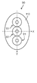
- FIG. 4A and 4B show a schematic cross-sectional view of the fiber bundle
- FIG. 5 shows the cross-sectional structure and the refractive index distribution of the first optical fiber.
- FIG. 4A shows a case where the outer shape of the cross section of the fiber bundle is circular
- FIG. 4B shows a case where the outer shape of the cross section of the fiber bundle is elliptical.
- the second optical fiber and the third optical fibers 92 and 93 also have the same structure as shown in FIG.
- the first to third fibers 91 to 93 are arranged so that their optical axes coincide with the Y axis.
- the first optical member 51 When performing welding, for example, when the laser light LB is incident on the first optical fiber 91, the first optical member 51 is first arranged at the above-mentioned first position in a state where the laser oscillation is not performed.
- the first motor 71 When laser oscillation is performed and the laser light LB is emitted from the laser resonator, the first motor 71 is rotated by a control signal from the controller 80 in the direction A shown in FIG. 2 at a predetermined angle, and the first motor 71 is rotated.
- the first optical member 51 tilts at a predetermined angle in the YZ plane about the holder 60a in response to the rotation of the 71.
- the angle between the light incident surface of the first optical member 51 and the optical axis of the laser light LB changes, and the optical path of the laser light LB is changed inside the first optical member 51.
- the laser beam LB whose optical axis has been changed is incident on the incident end face of the first optical fiber 91.
- the tilt angle of the first optical member 51 is adjusted so that the laser beam LB is incident on the core 91a of the first optical fiber 91.
- the refractive index of the core 91a is higher than that of the first clad 91b, and the incident laser beam LB is confined in the core 91a and propagates in the first optical fiber 91.
- the first motor 71 rotates the first optical member 51 at a different angle. By doing so, the laser beam LB moves in the Y direction by a predetermined distance at the incident end face of the bundle fiber 90 and is incident on the core of the second optical fiber 92. Further, when the laser beam LB is incident on the third optical fiber 93, the first motor 71 rotates the first optical member 51 at a different angle. By doing so, the laser beam LB moves in the Y direction by a predetermined distance at the incident end face of the bundle fiber 90 and is incident on the core of the third optical fiber 93.
- the first to third optical fibers 91 included in the fiber bundle 90 are tilted. From 93 to 93, an optical fiber to which the laser beam LB is incident can be selected. Further, this makes it possible to select the laser light emitting head from which the laser light LB is emitted.
- the selection of the optical fiber into which the laser beam LB is incident, the switching timing of the laser beam LB incident, and the like are performed according to the control signal from the controller 80 based on the laser processing program.
- the first optical member 51 may be moved out of the optical path. Needless to say, it can be left as it is.
- the laser light LB is inserted into the first to third optical fibers 91 to 93 in order has been described, but this is for convenience and does not have to be in this order. Further, when the position of the fiber bundle 90 is determined in advance so that the laser beam LB enters the core of the second fiber 92 located at the center position of the fiber bundle 90 while the first optical member 51 is moved out of the optical path, the second When the laser beam LB is inserted only into the fiber 92, it is possible to keep the first optical member 51 moved out of the optical path.
- the laser oscillator 10 that generates the laser light LB and the first to third optical fibers 91 to 93 are bundled so as to have a predetermined arrangement relationship.
- the fiber bundle 90, the beam control mechanism 20 provided in the laser oscillator 10, and the first to third optical fibers are attached to the respective emission ends and irradiate the laser beam LB toward the workpieces 201 to 203, respectively.
- the first to third laser light emitting heads 121 to 123 are provided at least.
- the beam control mechanism 20 is provided on the optical path of the condensing lens 30 that receives the laser light LB and condenses it at a predetermined magnification, and the laser light LB that travels between the condensing lens 30 and the incident end face of the fiber bundle 90. It has at least a first optical path changing mechanism 41 for changing the optical path of the laser beam LB and a controller 80 for controlling the operation of the first optical path changing mechanism 41.
- the beam control mechanism 20 causes a laser beam LB to be incident on an optical fiber selected from the first to third optical fibers 91 to 93, for example, the first optical fiber, and the first laser attached to the first optical fiber 91.
- the laser light LB is emitted from the light emitting head 121.
- the laser processing apparatus 1000 By using the laser processing apparatus 1000 as shown in FIG. 1 and appropriately switching the laser light emitting head from which the laser light LB is emitted, a large amount of workpieces are often laser-processed in factories and the like. In this case, by sharing the laser oscillator 10 connected to the plurality of laser light emitting heads, the laser processing apparatus 1000 can be miniaturized and the area can be reduced.
- Such a laser processing device 1000 by providing the above-mentioned beam control mechanism 20 in the laser oscillator 10, it is possible to easily and quickly switch the laser light emitting head from which the laser light LB is emitted. Further, this can reduce the man-hours and time required for switching the laser light emitting head, and can reduce the cost of laser processing.
- the first optical member 51 includes a predetermined position (first position) on the optical path of the laser beam LB traveling between the condenser lens 30 and the incident end faces of the first to third optical fibers 91 to 93 and the outside of the optical path. It is provided so that it can be moved between.
- the optical path of the laser beam LB can be easily changed. It can.
- Patent Document 2 even if the optical member is arranged in front of the condenser lens 30, the laser beam LB after passing through the condenser lens 30 is imaged at the focal position. The optical path cannot be changed.
- the laser beam LB is emitted by arranging the parallel flat plate-shaped first optical member 51 at the above-mentioned first position and tilting the first optical member 51 by the first motor 71.
- the optical fiber and, by extension, the laser light emitting head can be switched easily and at high speed.
- the thickness of the first optical member 51 is about 1 mm to several mm, and because it is installed in a narrow position between the condenser lens 30 and the fiber bundle 90 through which the focused laser light LB passes.
- the required size is small, and the first motor 71 makes it easy to tilt at high speed. In addition, it becomes easy to reciprocate within a predetermined angle range. As a result, the laser light emitting head from which the laser light LB is emitted can be switched at high speed.
- the laser beam LB is converted into parallel light before being incident on the condenser lens 30.
- the optical path and the optical axis of the laser beam LB emitted from the condenser lens 30 become constant, so that the optical path of the laser beam LB can be easily changed by the first optical path changing mechanism 41.
- a configuration in which three optical fibers 91 to 93 are bundled in a fiber bundle 90 is shown, but the present invention is not particularly limited to this.
- they may be provided adjacent to the optical fiber 93 or the optical fiber 91 in the Y-axis direction.
- FIG. 6 shows a schematic cross-sectional view of another fiber bundle
- FIG. 7 shows a schematic cross-sectional view of yet another fiber bundle.
- the number of optical members and motors connected thereto is increased according to the number of optical fibers included in the fiber bundle 90, so that the configuration shown in FIGS. 6 and 7 is configured.
- the laser light LB generated by the laser oscillator 10 can be incident on any of the optical fibers 91 to 103 included in each.
- the number of laser light emitting heads connected to one laser oscillator 10 can be increased, and the laser processing apparatus 1000 can be further miniaturized and the area can be reduced.
- the man-hours and time required to switch the laser light emitting head, and eventually the cost of laser processing can be further reduced.
- the first optical fiber 91 is arranged at the center as shown in FIGS. 6 and 7, and other light is used. It is preferable to arrange the fibers concentrically from the center. Further, in this case, it is preferable that the angles formed by the centers of the optical fibers adjacent to each other on the concentric circumference and the centers of the first optical fibers 91 are substantially the same. As shown in FIG. 7, there may be a plurality of concentric circles in which the optical fibers are arranged. Further, in this case, it is preferable to arrange the optical fibers at positions facing each other with the first optical fiber 91 interposed therebetween. As shown in FIGS.
- each optical fiber can be arranged at symmetrical positions around the first optical fiber 91, so that the operation of the optical path changing mechanism can be simplified and the optical fiber to which the laser light LB is incident can be switched. It can be done easily.
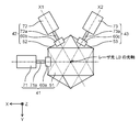
- ⁇ Modification example 1> 8 to 9 show a schematic view of the beam control mechanism according to this modification as viewed from the Z direction.
- FIGS. 8 to 9 the same parts as those in the first embodiment are designated by the same reference numerals, and detailed description thereof will be omitted.
- the second to third optical path changing mechanisms 42 to 43 are added in addition to the first optical path changing mechanism 41 to the configuration examples shown in FIGS. 2 to 3.
- the extending direction of the output shaft 71a of the first motor 71 of the first optical path changing mechanism 41 coincides with the X direction, but the output shafts 72a of the second to third motors 72 to 73 of the second to third optical path changing mechanisms 42 to 43
- the extending direction of ⁇ 73a coincides with the X1 axis and the X2 axis forming 60 degrees with the clockwise direction or the counterclockwise direction in the X direction in the XY plane.
- the second to third optical members are at the same position (first position) on the optical path of the laser beam LB traveling between the condenser lens 30 and the incident end surface of the fiber bundle 90. ) And the outside of the optical path are movable.
- FIG. 8 is a schematic view when the first optical member 51 is on the optical path of the laser beam LB and the second to third optical members 52 to 53 are outside the optical path.
- FIG. 9 is a schematic view when the first to third optical members 51 to 53 are all on the optical path of the laser light LB, but in reality, the first to third optical members 51 to 53 are Not all are on the optical path of the laser beam LB.
- the controller 80 selects any one of the first to third optical members 51 to 53, and arranges the selected one on the optical path of the laser beam LB.
- the controller 80 arranges the two unselected ones outside the optical path.
- the first optical member 51 When the laser beam LB is incident on the optical fiber on the Y-axis during the welding process, the first optical member 51 is first arranged at the above-mentioned first position in a state where the laser oscillation is not performed.
- the first motor 71 is controlled so that the laser beam LB is incident on the optical fiber on the Y axis, and the laser resonator is oscillated to perform welding.
- the laser oscillation is stopped and the first optical member 51 is moved out of the optical path.
- the third optical member 53 is arranged at the above-mentioned first position, and the laser beam LB is incident on the optical fiber on the X1 axis.
- the third motor 73 may be controlled.
- the second optical member 52 When welding is performed by incidenting the laser beam LB on the optical fiber on the X2 axis, the second optical member 52 is arranged at the above-mentioned first position, and the laser beam LB is incident on the optical fiber on the X2 axis.
- the second motor 72 may be controlled.
- the first to third optical members 51 to 53 are provided at the same position (first position) on the optical path of the laser beam LB traveling between the condenser lens 30 and the incident end surface of the fiber bundle 90. However, they may be provided at different positions. An example thereof will be described with reference to FIG.
- FIG. 10 shows a schematic view of the beam control mechanism according to the second modification as viewed from the X direction.
- the same parts as those in the first embodiment or the first modification are designated by the same reference numerals, and detailed description thereof will be omitted.
- the configuration according to the present modification is different from the configuration shown in the modification 1 in that the first to third optical members 51 to 53 are arranged at different positions on the optical path of the laser beam LB. Specifically, when the first optical member 51 is arranged on the optical path of the laser beam LB, it is arranged at the same position as in the first embodiment, and the second optical member 52 is arranged at a condenser lens 30 rather than the first position. The third optical member 53 is arranged at a position closer to the condenser lens 30 than the second optical member 52.
- the first to third motors 71 to 73 are also arranged at positions at predetermined intervals along the optical axis of the laser light LB.
- the beam control mechanism 20 may be configured in this way.
- the second optical member 52 or the third optical member 53 is placed at the first position of the laser beam LB. Can be moved.
- the second optical material 52 or the third optical material 53 can be moved to a predetermined position of the laser light LB while moving the first optical member 51 out of the optical path of the laser light LB. .. Therefore, the switching time before irradiating another optical fiber with the laser beam LB can be shortened.
- FIG. 11 shows the cross-sectional structure and the refractive index distribution of the first optical fiber according to the present embodiment.
- each of the optical fibers included in the fiber bundle 90 is a so-called multi-clad fiber.
- the first optical fiber 91 includes a core 91a, a first clad 91b provided coaxially with the core 91a on the outer peripheral side of the core 91a, and a core 91a on the outer peripheral side of the first clad 91b. It has a second clad 91c provided coaxially with the cable.
- the core 91a, the first clad 91b, and the second clad 91c are mainly composed of quartz, and as shown in FIG. 11, the core 91a has the highest refractive index, and the first clad 91b and the second clad 91c are refracted in this order. The rate is low.
- the refractive index of the first clad 91b and the second clad 91c may be adjusted by doping different types or concentrations of substances that can both reduce the refractive index.
- the index of refraction of the core 91a may also be adjusted by doping different types or concentrations of substances that can increase the index of refraction.
- the laser beam LB incident on the core 91a at a predetermined angle can propagate in the core 91a without entering the first clad 91b.
- the laser beam LB incident on the first clad 91b at a predetermined angle can propagate in the first clad 91b without entering the second clad 91c.
- the structure shown in FIG. 10 is merely an example, and the refractive indexes of the core 91a, the first clad 91b, and the second clad 91c are necessarily different. It is not necessary to have.
- the core 91a, the first clad 91b, and the second clad 91c have the same refractive index N1, and between the core 91a and the first clad 91b, and between the first clad 91b and the second clad 91c.
- a thin layer having a refractive index N2 (N2 ⁇ N1) may be provided.
- the laser beam LB incident on the core 91a at a predetermined angle can propagate in the core 91a without entering the first clad 91b, but is incident on the first clad 91b at a predetermined angle.
- the resulting laser beam LB can propagate in the first clad 91b without entering the second clad 91c.
- the main component of the layer having a refractive index N2 is quartz, but a substance capable of lowering the refractive index may be doped.
- the laser beam LB incident on the first optical fiber 91 propagates through the core 91a and / or the first clad 91b and reaches the exit end of the first optical fiber 91.
- a film or a resin-based protective layer that mechanically protects the first optical fiber 91 is provided on the outer peripheral surface of the second clad 91c.
- the laser light LB at the incident end face of the first optical fiber 91 The incident position can be changed. This will be described further.
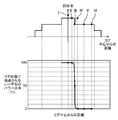
- FIG. 12 shows the relationship between the incident position of the laser light on the incident end face of the first optical fiber and the power ratio of the laser light transmitted inside the core
- FIG. 13 shows the relationship between the laser light on the incident end face of the first optical fiber.
- the relationship between the incident position and the beam profile of the laser beam emitted from the first laser beam emitting head is shown.
- the beam profile shown in FIG. 13 corresponds to the power distribution of the laser light LB emitted from the first laser light emitting head 121 and imaged at the focal position.
- the beam profile shown in FIG. 13 also corresponds to the power distribution of the laser beam LB emitted from the emission end of the first optical fiber 91.
- the laser light LB When the incident position of the laser light LB is I shown in FIG. 12, the laser light LB is 100% incident in the core 91a, and the beam profile of the laser light LB has a single peak shape with a narrow half-value width as shown in FIG. (Incident position of laser beam LB: I).
- 100% of the laser beam LB is incident on the core 91a until the incident position of the laser beam LB approaches the position II shown in FIG. 12 from the core 91a, and the beam profile is single peak. Maintained in shape.
- the beam profile changes so as to include a single peak-shaped portion and a terrace-shaped portion having a wide half-value width formed on both sides thereof (incident position of laser beam LB: ⁇ III). ).
- the former corresponds to the laser beam LB incident in the core 91a
- the latter corresponds to the laser beam LB transmitted in the first clad 91b.
- the peak value of the single peak-shaped portion decreases.
- the power ratio of the laser light LB incident in the core 91a becomes equal to the power ratio of the laser light LB incident in the first clad 91b.
- the cross-sectional area of the core 91a is equal to the cross-sectional area of the first clad 91b, the peak value of the single peak-shaped portion and the peak value of the terrace-shaped portion of the beam profile coincide with each other, which is shown in FIG.
- the beam profile of the entire laser beam LB has a single peak shape, its peak value is lower and the half-value width is larger than that in the case where the laser beam LB is incident only in the core 91a (laser beam).
- Incident position of LB III
- the beam profile has a single-peaked portion and a terrace-like shape having a wide half-value width formed on both sides thereof, as shown in FIG. The shape is such that it includes the portion of (incident position of laser beam LB: ⁇ III).
- the beam profile becomes bimodal as shown in FIG. 13 (incident position of the laser beam LB: ⁇ IV).
- the incident position of the laser beam LB moves away from the core 91a (between III and IV shown in FIG. 12), the power of the laser beam LB incident in the core 91a decreases and is incident in the first clad 91b.
- the power ratio of the laser beam LB to be generated becomes high.
- the peak value of the portion of the beam profile corresponding to the component transmitted in the core 91a decreases, and the peak value of the portion corresponding to the component transmitted in the first clad 91b decreases.
- the value increases and the beam profile becomes bimodal (incident position of laser beam LB: ⁇ IV).
- the peak value in the bimodal beam profile is lower than the peak value in the monomodal beam profile obtained when the incident position of the laser beam LB is I shown in FIG.
- the incident position of the laser is further separated from the core 91a (between IV and V shown in FIG. 12)
- the power of the laser light LB incident in the core 91a becomes 0%
- the laser The light LB is 100% incident in the first clad 91b.
- the incident position of the laser beam LB When the incident position of the laser beam LB is completely within the second clad 91c (positions V to VI shown in FIG. 12), as shown in FIG. 13, it corresponds to the component transmitted into the core 91a of the beam profile.
- the peak value of the portion is reduced to 0%, the peak value of the portion corresponding to the component transmitted in the first clad 91b is maximized, and the beam profile is bimodal with the highest peak value (laser light LB).
- Incident position In the case of V to VI).
- the peak value in the bimodal beam profile is lower than the peak value in the monomodal beam profile obtained when the incident position of the laser beam LB is I shown in FIG.
- the beam control mechanism 20 is configured to switch the power distribution of the laser light LB emitted from the first laser light emitting head 121 during the laser processing of the work 201.
- the processed shape of the work 201 for example, the welded shape can be made good. This will be described further.
- FIG. 14 shows a schematic cross-sectional view of the welded portion of the work for comparison
- FIG. 15 shows a schematic cross-sectional view of the welded portion of the work according to the present embodiment.
- the portion irradiated with the laser beam is heated to cause melting, and a molten pool is formed. Further, in the portion irradiated with the laser beam, the material constituting the work evaporates on the surface, and the reaction force forms a keyhole inside the work.
- the laser light LB is transmitted only into the core 91a of the first optical fiber 91 and is irradiated from the first laser light emitting head 121 toward the work 201, and the laser light LB at the welded portion
- the power density is high, and the spot diameter of the irradiated laser beam LB is small.
- the work 201 is likely to be blended and the keyhole 220 is deepened, while the opening 221 of the keyhole 220 is not so widened, and as shown in FIG. 14, the constricted portion 222 is inside the keyhole 220. May occur. Further, when the constricted portion 222 is closed, air bubbles 223 remain inside the work 201. Further, when the closed constricted portion 222 becomes the keyhole 220 again, if the molten metal suddenly ejects from the inside of the keyhole 220 toward the surface, the spatter 212 adheres to the surface of the work 201 or the molten pool 210 The surface of the surface is rippling.
- the molten pool 210 is rapidly cooled and solidified after passing through the laser beam LB, when such a wave is generated, the unevenness 211 (on the surface of the work 201 behind the molten pool 210 along the traveling direction of laser welding) The rear vibrating portion 211) is generated.
- this wave is reflected and bounces off at the boundary between the molten pool 210 and the solidified part.
- this reflected wave reaches the keyhole 220, it flows so as to fill the keyhole 220.
- the molten metal that has flowed in is rapidly heated by the laser beam LB, and suddenly generates metal vapor, so that the columnar shape of the keyhole 220 is disturbed.
- the irregular shape of the keyhole 220, the generation of air bubbles 223, and the spatter 212 and unevenness 211 generated on the surface of the work 201, which have been described above, have been factors that deteriorate the welding quality.
- the power distribution of the laser beam LB emitted from the first laser beam emitting head 121 toward the work 201 can be changed by using the beam control mechanism 20. Therefore, for example, by adjusting the tilt angle of the first optical member 51, the power of the laser light LB transmitted in the core 91a of the first optical fiber 91 and the laser light LB transmitted in the first clad 91b By changing the ratio, the laser beam LB having a beam profile as shown in FIG. 15 can be irradiated toward the work 201.
- the desired penetration depth D can be obtained by the laser beam LB emitted from the core 91a.
- the laser beam LB emitted from the first clad 91b can widen the opening 221 of the keyhole 220 as compared with the case shown in FIG.
- the inner wall surface of the keyhole 220 is also irradiated with the laser beam LB, and the laser beam LB is absorbed by the work 201 in the process of the laser beam LB reaching the inside of the keyhole 220 by multiple reflection.
- the welding quality can be improved by switching the power distribution of the laser beam LB emitted from the first laser beam emitting head 121 during laser welding.
- FIG. 16 shows the welding sequence of the work, and the molten pool 210 is not formed in the work 201 immediately after the start of welding.
- the controller 80 drives the first motor 71 to incident the laser beam LB only on the core 91a.
- the spot diameter of the laser beam LB irradiated to the work 201 is reduced, and the power density of the laser beam LB at the welded portion is increased (first irradiation step).
- the molten pool 210 and the keyhole 220 it is desired to suppress the formation of the constricted portion 222 and the like as described above.
- the controller 80 drives the first motor 71 to inject the laser beam LB into the core 91a and the first clad 91b.
- the opening 221 of the keyhole 220 is widened, and the desired penetration depth D is obtained (second irradiation step).
- the second laser light irradiation head 122 and the third laser light irradiation head 123 are also used, the workpieces 202 and 203 are laser welded in the same sequence, respectively.
- the notation of switching the laser light LB to the second to third laser light irradiation heads 122 to 123 is omitted.
- the molten pool 210 and the keyhole 220 can be reliably formed in the workpieces 201 to 203, and the generation of air bubbles 223 inside the workpieces 201 to 203 and surface irregularities 211 and the like can be suppressed. Therefore, the welding quality can be improved.
- the beam control mechanism 20 is operated according to the material of the works 201 to 203 and / or the shape of the laser processing target portion in the works 201 to 203, and the laser light emitting head is used from any of the plurality of laser light emitting heads.
- the workpieces 201 to 203 having various materials and shapes can be laser-machined, and the processing quality thereof can be improved.
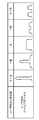
- FIG. 17 shows a periodic change in the beam profile of the laser beam.
- the first optical fiber 91 in the present embodiment is a multi-clad fiber as shown in the second embodiment.
- the first optical member 51 by reciprocating the first motor 71 within a predetermined angle range, the first optical member 51 also reciprocates within a predetermined angle range accordingly. That is, the beam control mechanism 20 is configured to periodically switch the power distribution of the laser light LB emitted from the first laser light emitting head 121 during the laser processing of the work 201.
- the rotation frequency of the first optical member 51 is set to about several Hz to several kHz.
- the second motor 72 and the third motor 73 can also reciprocate within an angle range, and accordingly, the second optical member 52 and the third optical member 53 are also predetermined. It reciprocates within an angular range.
- the power distribution of the laser light LB emitted from the emission end of the first laser light emission head 121 changes periodically. Specifically, the beam profile having a single peak-like peak is continuously changed to a beam profile having a bimodal peak, and the change is periodically repeated. Further, the rotation frequency of the first optical member 51 corresponds to the frequency at which the power distribution of the laser beam LB changes.
- the molten pool 210 and the keyhole 220 are surely formed in the work 201, the keyhole 220 is prevented from becoming too narrow, and the generation of air bubbles 223 and spatter 212 is suppressed.
- Laser welding can be performed.
- the power distribution of the laser beam LB at a predetermined frequency, in this case, a frequency substantially equal to the natural vibration frequency of the keyhole 220 formed in the work 201, behind the molten pool 210 described above.
- the unevenness 211 to be formed can be reduced, and the shape disorder of the keyhole 220 can be effectively suppressed. This will be described further.
- the keyhole 220 In the process of sequentially forming the molten pool 210 along the direction of laser welding, the keyhole 220 also moves along the direction of laser welding. At this time, the keyhole 220 vibrates repeatedly in the radial direction and / or the depth direction in the radial direction and / or the depth direction at a natural vibration frequency (hereinafter, simply referred to as a natural vibration frequency). ..
- the natural vibration frequency is a value determined by the size of the molten pool 210, the viscosity of the constituent metal of the molten work at the time of melting, and the like, and is estimated to be about several Hz to several kHz in many cases.
- the shape of the keyhole 220 is stabilized and the constricted portion 222 is generated inside the work 201.
- the generation of bubble 223 can be suppressed.
- the unevenness 211 formed behind the molten pool 210 can be reduced.
- the method of changing the power distribution of the laser beam LB periodically and continuously as described above is particularly effective for thick plate welding. This is because the thicker the plate, the deeper the required penetration, and the deeper the keyhole 220 to achieve it, so there is a probability that welding defects will occur due to the instability of the keyhole 220 (for example, constriction). This is because it becomes expensive.
- the first optical fiber 91 in this modification is a multi-clad fiber as shown in the second embodiment.
- FIG. 18 shows a welding sequence of the work according to the present modification, and the work 201 has a shape having a thin plate portion and a thick plate portion continuous thereto.
- the thickness of the thick plate portion is thicker than that of the thin plate portion.
- the work 201 is irradiated with the laser beam LB in the sequence shown in FIG.
- the penetration depth D does not have to be too deep. Therefore, after the work 201 is irradiated with the laser beam LB with a beam profile having a single peak at the start of welding to form the molten pool 210 and the keyhole 220, the power distribution of the laser beam LB becomes broad. To prevent the formation of the constricted portion 222 in the keyhole 220.
- the work 201 is irradiated with the laser beam LB in the sequence shown in FIG. That is, the laser beam LB is irradiated toward the work 201 while periodically changing the power distribution of the laser beam LB at the natural vibration frequency.
- the thin plate portion may be welded while the power distribution of the laser beam LB is fixed so as to be broad from the beginning.
- the first optical member 51 is configured to be movable inside and outside the optical path of the laser beam LB, but the present invention is not particularly limited to this, and the first optical member 51 may be fixedly arranged in the optical path of the laser beam LB. .. However, even in that case, the first optical member 51 can rotate around the axis of the output shaft 71a. In this case, the second optical member 52 or the third optical member 53 is placed outside the optical path of the laser beam LB. Similarly, the second optical member 52 and the third optical member 53 may be fixed in the optical path of the laser beam LB.
- the second optical member 52 and the third optical member 53 can rotate around the axis of the output shaft 72a and the axis of the output shaft 73a, respectively.
- the remaining two optical members are placed outside the optical path of the laser beam LB.
- the multi-clad fiber having the structure shown in FIG. 11 has been described as an example in the second and third embodiments including the third modification, other structures may be used.
- one or more clads may be provided on the outer peripheral side of the second clad 91c.
- the refractive index of the clad provided on the outside of the second clad 91c may be gradually lowered.
- the clad to which the laser beam LB can be incident may be up to the clad excluding the outermost clad.
- a film or a resin-based protective layer that mechanically protects the fiber is provided outside the outermost clad.
- the output and wavelength of the laser beam LB can be appropriately changed depending on the material and shape of the work or the processing content.
- actuators other than the first to third motors 71 to 73 for example, a piezoelectric actuator or the like may be used.
- the so-called keyhole type laser welding in which the keyhole 220 is formed in the molten pool 210 has been described as an example, but the material and shape of the work, the required penetration depth D, and the like.
- the type of laser welding can be appropriately selected depending on the width of the welding bead and the like.
- the above-mentioned laser processing apparatus 1000 and welding sequence can be applied not only to laser welding but also to laser cutting.
- the laser processing device of the present invention can easily switch the laser light emitting head from which the laser light is emitted, and is useful as a laser processing device capable of processing a large amount of workpieces.
- Laser oscillator 20 Beam control mechanism 30 Condensing lens 41 to 43 First to third optical path changing mechanisms 51 to 53 First to third optical members 60a, 60b, 60c Holders 71 to 73 First to third motor 80 Controller 90 Fiber bundles 91 to 93 1st to 3rd optical fibers 91a Core 91b 1st clad 91c 2nd clad 121 to 123 1st to 3rd laser light emitting heads 131 to 133 1st to 3rd manipulators 201 to 203 Work 210 Molten pond 220 Keyhole 221 Opening 1000 Laser processing equipment LB Laser light
Landscapes
- Physics & Mathematics (AREA)
- Optics & Photonics (AREA)
- Engineering & Computer Science (AREA)
- Plasma & Fusion (AREA)
- Mechanical Engineering (AREA)
- Robotics (AREA)
- Laser Beam Processing (AREA)
Abstract
L'invention concerne un dispositif d'usinage au laser comprenant un oscillateur laser, des fibres optiques 1ère-3ème, un mécanisme de commande de faisceau, et des têtes de projection de faisceau laser 1ère-3ème qui sont respectivement fixées aux fibres optiques 1ère-3ème. Le mécanisme de commande de faisceau comprend : une lentille de focalisation ; des mécanismes de changement du trajet lumineux 1er-3ème qui sont disposés sur le trajet lumineux d'un faisceau laser LB après que celui-ci a traversé la lentille de focalisation ; et un contrôleur qui commande le fonctionnement des mécanismes de changement du trajet lumineux 1er-3ème. Le mécanisme de commande de faisceau amène un faisceau laser à être projeté depuis la première tête de projection laser par le biais de la première fibre optique, qui a été sélectionnée.
Priority Applications (3)
| Application Number | Priority Date | Filing Date | Title |
|---|---|---|---|
| JP2021522717A JP7382553B2 (ja) | 2019-05-29 | 2020-04-24 | レーザ加工装置及びそれを用いたレーザ加工方法 |
| EP20814581.3A EP3978182A4 (fr) | 2019-05-29 | 2020-04-24 | Dispositif d'usinage au laser et procédé d'usinage au laser utilisant celui-ci |
| US17/529,911 US20220072655A1 (en) | 2019-05-29 | 2021-11-18 | Laser processing device and laser processing method using same |
Applications Claiming Priority (2)
| Application Number | Priority Date | Filing Date | Title |
|---|---|---|---|
| JP2019-100183 | 2019-05-29 | ||
| JP2019100183 | 2019-05-29 |
Related Child Applications (1)
| Application Number | Title | Priority Date | Filing Date |
|---|---|---|---|
| US17/529,911 Continuation US20220072655A1 (en) | 2019-05-29 | 2021-11-18 | Laser processing device and laser processing method using same |
Publications (1)
| Publication Number | Publication Date |
|---|---|
| WO2020241137A1 true WO2020241137A1 (fr) | 2020-12-03 |
Family
ID=73554054
Family Applications (1)
| Application Number | Title | Priority Date | Filing Date |
|---|---|---|---|
| PCT/JP2020/017620 WO2020241137A1 (fr) | 2019-05-29 | 2020-04-24 | Dispositif d'usinage au laser et procédé d'usinage au laser utilisant celui-ci |
Country Status (4)
| Country | Link |
|---|---|
| US (1) | US20220072655A1 (fr) |
| EP (1) | EP3978182A4 (fr) |
| JP (1) | JP7382553B2 (fr) |
| WO (1) | WO2020241137A1 (fr) |
Citations (6)
| Publication number | Priority date | Publication date | Assignee | Title |
|---|---|---|---|---|
| JPS5942502A (ja) * | 1982-08-31 | 1984-03-09 | Matsushita Electric Ind Co Ltd | 赤外光導光路 |
| JPS6116938Y2 (fr) * | 1981-10-16 | 1986-05-24 | ||
| JP2002273586A (ja) * | 2001-03-16 | 2002-09-25 | National Institute For Materials Science | レーザ溶接方法 |
| JP2003001464A (ja) * | 2001-06-22 | 2003-01-08 | Nippei Toyama Corp | レーザ加工装置及びレーザ加工方法 |
| US8781269B2 (en) | 2010-04-08 | 2014-07-15 | Trumpf Laser- Und Systemtechnik Gmbh | Method and arrangement for generating a laser beam having a differing beam profile characteristic by means of a multi-clad fiber |
| US20180159299A1 (en) * | 2016-12-02 | 2018-06-07 | Wang-Long Zhou | Laser systems utilizing fiber bundles for power delivery and beam switching |
Family Cites Families (6)
| Publication number | Priority date | Publication date | Assignee | Title |
|---|---|---|---|---|
| JP2777138B2 (ja) | 1988-03-16 | 1998-07-16 | 株式会社ニデック | 医用レーザ装置3 |
| US4927226A (en) * | 1989-03-27 | 1990-05-22 | General Electric Company | Multiplexer for high power CW lasers |
| US6515257B1 (en) * | 2001-03-26 | 2003-02-04 | Anvik Corporation | High-speed maskless via generation system |
| US8803029B2 (en) * | 2006-08-03 | 2014-08-12 | Chrysler Group Llc | Dual beam laser welding head |
| DE102011003686A1 (de) * | 2011-02-07 | 2012-08-09 | Trumpf Laser- Und Systemtechnik Gmbh | Laserbearbeitungsvorrichtung |
| JP6384786B2 (ja) | 2014-08-19 | 2018-09-05 | パナソニックIpマネジメント株式会社 | 照明装置 |
-
2020
- 2020-04-24 WO PCT/JP2020/017620 patent/WO2020241137A1/fr unknown
- 2020-04-24 JP JP2021522717A patent/JP7382553B2/ja active Active
- 2020-04-24 EP EP20814581.3A patent/EP3978182A4/fr active Pending
-
2021
- 2021-11-18 US US17/529,911 patent/US20220072655A1/en active Pending
Patent Citations (6)
| Publication number | Priority date | Publication date | Assignee | Title |
|---|---|---|---|---|
| JPS6116938Y2 (fr) * | 1981-10-16 | 1986-05-24 | ||
| JPS5942502A (ja) * | 1982-08-31 | 1984-03-09 | Matsushita Electric Ind Co Ltd | 赤外光導光路 |
| JP2002273586A (ja) * | 2001-03-16 | 2002-09-25 | National Institute For Materials Science | レーザ溶接方法 |
| JP2003001464A (ja) * | 2001-06-22 | 2003-01-08 | Nippei Toyama Corp | レーザ加工装置及びレーザ加工方法 |
| US8781269B2 (en) | 2010-04-08 | 2014-07-15 | Trumpf Laser- Und Systemtechnik Gmbh | Method and arrangement for generating a laser beam having a differing beam profile characteristic by means of a multi-clad fiber |
| US20180159299A1 (en) * | 2016-12-02 | 2018-06-07 | Wang-Long Zhou | Laser systems utilizing fiber bundles for power delivery and beam switching |
Non-Patent Citations (1)
| Title |
|---|
| See also references of EP3978182A4 |
Also Published As
| Publication number | Publication date |
|---|---|
| US20220072655A1 (en) | 2022-03-10 |
| EP3978182A1 (fr) | 2022-04-06 |
| JPWO2020241137A1 (fr) | 2020-12-03 |
| JP7382553B2 (ja) | 2023-11-17 |
| EP3978182A4 (fr) | 2022-08-24 |
Similar Documents
| Publication | Publication Date | Title |
|---|---|---|
| JP6602860B2 (ja) | レーザ加工装置及びレーザ加工方法 | |
| KR100745295B1 (ko) | 레이저 용접 장치, 레이저 용접 기기 및 레이저 용접 방법 | |
| JP5114874B2 (ja) | レーザ溶接方法およびレーザ溶接装置 | |
| US20210162539A1 (en) | Welding method and welding apparatus | |
| JP2001276988A (ja) | レーザ加工装置 | |
| JP2008503355A (ja) | 基板材料の切断、分断または分割装置、システムおよび方法 | |
| JP4792740B2 (ja) | レーザ溶接の制御装置および制御方法 | |
| TW201815502A (zh) | 利用控制相對於輔助氣流作光軸定位進行金屬材料雷射加工的方法以及實施該方法的機器及電腦程式 | |
| JPWO2019176502A1 (ja) | レーザ発振器、それを用いたレーザ加工装置及びレーザ発振方法 | |
| WO2020241138A1 (fr) | Dispositif d'usinage au laser et procédé d'usinage au laser l'utilisant | |
| JP7445879B2 (ja) | デュアル波長レーザシステム及びそのシステムを用いた材料加工 | |
| JPH10314973A (ja) | 複合レーザビームによるレーザ加工装置および加工法 | |
| KR20110129791A (ko) | 레이저 가공 시스템 및 이를 이용한 레이저 가공 방법 | |
| WO2020241136A1 (fr) | Dispositif d'usinage laser et procédé d'usinage laser faisant appel audit dispositif | |
| WO2020241137A1 (fr) | Dispositif d'usinage au laser et procédé d'usinage au laser utilisant celui-ci | |
| JP2005254618A (ja) | 樹脂溶着装置 | |
| JP7369915B2 (ja) | レーザ溶接装置及びそれを用いたレーザ溶接方法 | |
| CN115815806A (zh) | 激光焊接装置 | |
| JP2006281304A (ja) | レーザ溶接装置、レーザ溶接システム、およびレーザ溶接方法 | |
| WO2021166037A1 (fr) | Machine de traitement au laser | |
| JP2018176229A (ja) | 溶接装置および溶接方法 | |
| WO2021095253A1 (fr) | Procédé de découpage au laser et dispositif de découpage au laser | |
| WO2023190933A1 (fr) | Appareil et procédé d'usinage laser | |
| JP2003048095A (ja) | レーザ加工ヘッド及びこれを用いる加工方法 | |
| WO2023149458A1 (fr) | Procédé de soudage au laser et dispositif de soudage au laser |
Legal Events
| Date | Code | Title | Description |
|---|---|---|---|
| 121 | Ep: the epo has been informed by wipo that ep was designated in this application |
Ref document number: 20814581 Country of ref document: EP Kind code of ref document: A1 |
|
| ENP | Entry into the national phase |
Ref document number: 2021522717 Country of ref document: JP Kind code of ref document: A |
|
| NENP | Non-entry into the national phase |
Ref country code: DE |
|
| ENP | Entry into the national phase |
Ref document number: 2020814581 Country of ref document: EP Effective date: 20220103 |