WO2020241137A1 - Laser machining device and laser machining method using same - Google Patents
Laser machining device and laser machining method using same Download PDFInfo
- Publication number
- WO2020241137A1 WO2020241137A1 PCT/JP2020/017620 JP2020017620W WO2020241137A1 WO 2020241137 A1 WO2020241137 A1 WO 2020241137A1 JP 2020017620 W JP2020017620 W JP 2020017620W WO 2020241137 A1 WO2020241137 A1 WO 2020241137A1
- Authority
- WO
- WIPO (PCT)
- Prior art keywords
- laser
- optical
- laser beam
- laser processing
- laser light
- Prior art date
Links
Images


Classifications
-
- B—PERFORMING OPERATIONS; TRANSPORTING
- B23—MACHINE TOOLS; METAL-WORKING NOT OTHERWISE PROVIDED FOR
- B23K—SOLDERING OR UNSOLDERING; WELDING; CLADDING OR PLATING BY SOLDERING OR WELDING; CUTTING BY APPLYING HEAT LOCALLY, e.g. FLAME CUTTING; WORKING BY LASER BEAM
- B23K26/00—Working by laser beam, e.g. welding, cutting or boring
- B23K26/02—Positioning or observing the workpiece, e.g. with respect to the point of impact; Aligning, aiming or focusing the laser beam
- B23K26/06—Shaping the laser beam, e.g. by masks or multi-focusing
- B23K26/064—Shaping the laser beam, e.g. by masks or multi-focusing by means of optical elements, e.g. lenses, mirrors or prisms
- B23K26/0648—Shaping the laser beam, e.g. by masks or multi-focusing by means of optical elements, e.g. lenses, mirrors or prisms comprising lenses
-
- B—PERFORMING OPERATIONS; TRANSPORTING
- B23—MACHINE TOOLS; METAL-WORKING NOT OTHERWISE PROVIDED FOR
- B23K—SOLDERING OR UNSOLDERING; WELDING; CLADDING OR PLATING BY SOLDERING OR WELDING; CUTTING BY APPLYING HEAT LOCALLY, e.g. FLAME CUTTING; WORKING BY LASER BEAM
- B23K26/00—Working by laser beam, e.g. welding, cutting or boring
- B23K26/02—Positioning or observing the workpiece, e.g. with respect to the point of impact; Aligning, aiming or focusing the laser beam
- B23K26/06—Shaping the laser beam, e.g. by masks or multi-focusing
- B23K26/064—Shaping the laser beam, e.g. by masks or multi-focusing by means of optical elements, e.g. lenses, mirrors or prisms
- B23K26/0643—Shaping the laser beam, e.g. by masks or multi-focusing by means of optical elements, e.g. lenses, mirrors or prisms comprising mirrors
-
- B—PERFORMING OPERATIONS; TRANSPORTING
- B23—MACHINE TOOLS; METAL-WORKING NOT OTHERWISE PROVIDED FOR
- B23K—SOLDERING OR UNSOLDERING; WELDING; CLADDING OR PLATING BY SOLDERING OR WELDING; CUTTING BY APPLYING HEAT LOCALLY, e.g. FLAME CUTTING; WORKING BY LASER BEAM
- B23K26/00—Working by laser beam, e.g. welding, cutting or boring
- B23K26/02—Positioning or observing the workpiece, e.g. with respect to the point of impact; Aligning, aiming or focusing the laser beam
- B23K26/06—Shaping the laser beam, e.g. by masks or multi-focusing
- B23K26/067—Dividing the beam into multiple beams, e.g. multifocusing
- B23K26/0673—Dividing the beam into multiple beams, e.g. multifocusing into independently operating sub-beams, e.g. beam multiplexing to provide laser beams for several stations
-
- B—PERFORMING OPERATIONS; TRANSPORTING
- B23—MACHINE TOOLS; METAL-WORKING NOT OTHERWISE PROVIDED FOR
- B23K—SOLDERING OR UNSOLDERING; WELDING; CLADDING OR PLATING BY SOLDERING OR WELDING; CUTTING BY APPLYING HEAT LOCALLY, e.g. FLAME CUTTING; WORKING BY LASER BEAM
- B23K26/00—Working by laser beam, e.g. welding, cutting or boring
- B23K26/08—Devices involving relative movement between laser beam and workpiece
- B23K26/0869—Devices involving movement of the laser head in at least one axial direction
- B23K26/0876—Devices involving movement of the laser head in at least one axial direction in at least two axial directions
- B23K26/0884—Devices involving movement of the laser head in at least one axial direction in at least two axial directions in at least in three axial directions, e.g. manipulators, robots
-
- B—PERFORMING OPERATIONS; TRANSPORTING
- B23—MACHINE TOOLS; METAL-WORKING NOT OTHERWISE PROVIDED FOR
- B23K—SOLDERING OR UNSOLDERING; WELDING; CLADDING OR PLATING BY SOLDERING OR WELDING; CUTTING BY APPLYING HEAT LOCALLY, e.g. FLAME CUTTING; WORKING BY LASER BEAM
- B23K26/00—Working by laser beam, e.g. welding, cutting or boring
- B23K26/20—Bonding
- B23K26/21—Bonding by welding
Definitions
- the present invention relates to a laser processing apparatus and a laser processing method using the laser processing apparatus.
- Such a laser processing apparatus includes a plurality of optical fibers connected to one laser oscillator, and a laser light emitting head attached to each of the plurality of optical fibers. Further, this laser processing apparatus appropriately switches the optical fiber to which the laser light is transmitted, and transmits the laser light to the selected laser light emitting head.
- Patent Document 1 discloses a laser system in which a laser beam is incident on a plurality of bundled optical fibers that can be optically coupled to the laser beam.
- the laser system includes a reflector or condenser lens located on the optical path of the laser beam and a piezo actuator to move them.
- the piezo actuator causes the laser beam to be incident on a selected optical fiber among the plurality of optical fibers by changing the incident position of the laser beam on the plurality of bundled optical fibers.
- the optical fiber is made of a multi-clad fiber.
- the laser system changes the beam profile of the laser beam by adjusting the incident position of the laser beam.
- Patent Document 2 by moving the position of the condenser lens or inserting a wedge-shaped optical element on the optical path of the laser beam, the incident position of the laser beam at the incident end of the multi-clad fiber can be determined.
- a variable configuration has been proposed.
- Patent Document 2 in order to move the position of the condenser lens and change the incident position of the laser beam, it is necessary to move the condenser lens in a straight line by an actuator, so that the position accuracy is correct. There was a problem in achieving both responsiveness and responsiveness.
- the present invention has been made in view of this point, and an object of the present invention is to easily and quickly switch the laser beam emitting head into which the laser beam is incident in a laser processing apparatus provided with a plurality of laser beam emitting heads. It is an object of the present invention to provide a laser processing apparatus capable of the above and a laser processing method using the same.
- the laser processing apparatus includes a laser oscillator that generates laser light, a fiber bundle in which a plurality of optical fibers are bundled so as to have a predetermined arrangement relationship, and the laser oscillator.
- the beam control mechanism is provided with at least a beam control mechanism provided in the above and a plurality of laser light emitting heads attached to each emission end of the plurality of optical fibers and irradiating the laser light toward the work.
- a condensing lens that receives the laser light and condenses it at a predetermined magnification, and a condensing lens that travels between the condensing lens and the incident end face of the fiber bundle, and is provided on the optical path of the laser light.
- the beam control mechanism has at least a plurality of optical path changing mechanisms for changing the optical path and a controller for controlling the operation of the plurality of optical path changing mechanisms, and the beam control mechanism is one optical fiber selected from the plurality of optical fibers. It is characterized in that the laser beam is incident on the laser beam and the laser beam is emitted from the laser beam emitting head attached to the one optical fiber.
- the laser processing method according to the present invention is a laser processing method using the laser processing apparatus, which comprises a first irradiation step of irradiating the work with the laser beam having a first power distribution, followed by the above-mentioned. It is characterized by including at least a second irradiation step of irradiating the laser beam having a second power distribution different from the first power distribution toward the work.
- a molten pool and a keyhole can be surely formed in the work at the initial stage of welding, and the welding quality of the work can be improved.
- the laser processing apparatus of the present invention it is possible to easily and quickly switch the laser light emitting head from which the laser light is emitted. According to the laser processing method of the present invention, the welding quality of the workpiece can be improved.
- FIG. 5 is a schematic cross-sectional view of yet another fiber bundle. It is a schematic diagram which looked at the beam control mechanism from the Z direction.
- FIG. This is a welding sequence of the work according to the second embodiment. It is a figure which shows the periodic change of the beam profile of a laser beam. It is a welding sequence of the work which concerns on the modification 3.
- FIG. 1 shows a schematic diagram of the configuration of the laser processing apparatus according to the present embodiment, and the laser processing apparatus 1000 includes a laser oscillator 10, a beam control mechanism 20, a controller 80, a fiber bundle 90, and first to third laser light emission.
- the heads 121 to 123 and the first to third manipulators 131 to 133 are provided.
- the laser oscillator 10 is a laser light source that generates laser light LB by receiving electric power from a power source (not shown).
- the laser oscillator 10 may be composed of a single laser light source or a plurality of laser modules. In the latter case, the laser light emitted from each of the plurality of laser modules is combined and emitted as the laser light LB.
- the beam control mechanism 20 is provided in the laser oscillator 10 and transmits the laser light LB to the selected optical fiber in the fiber bundle 90.
- the configuration and operation of the beam control mechanism 20 will be described later.
- the beam control mechanism 20 can also control the power distribution of the laser beam LB emitted from the exit end of the optical fiber, which will also be described later.
- the fiber bundle 90 is an optical component in which the first to third optical fibers 91 to 93 are bundled.
- the first optical fiber 91 has a core 91a and a first clad 91b provided coaxially with the core 91a on the outer peripheral side of the core 91a (see FIG. 5).
- the second and third optical fibers 92 and 93 also have a core and a first cladding (neither shown).
- a film or a resin-based protective layer that mechanically protects the optical fiber is provided on the outer peripheral surface of the first clad 91b.
- the first to third optical fibers 91 to 93 are covered with a protective member 110 made of resin or the like in a bundled state, and the arrangement relationship with each other is fixed (see FIGS. 4A and 4B).
- Each of the first to third laser light emitting heads 121 to 123 is attached to the emitting end of the corresponding optical fiber, and irradiates the laser light LB transmitted by the optical fiber toward the workpieces 201 to 203.
- the works 201 to 203 are laser-machined by the laser beam LB.
- Optical components such as a collimator lens, a condenser lens, and a protective glass are arranged inside the first to third laser light emitting heads 121 to 123, respectively.
- the controller 80 controls the laser oscillation of the laser oscillator 10. Specifically, laser oscillation control is performed by supplying control signals such as an output current and an on / off time to a power source (not shown) connected to the laser oscillator 10.
- the controller 80 is a first motor 71 (see FIGS. 3A and 3B) or a second motor 72 and a third motor 73 (FIG. 8) provided in the beam control mechanism 20 according to the content of the selected laser machining program. Refer to) for drive control. Further, the controller 80 controls the operation of the first to third manipulators 131 to 133.
- the laser machining program is stored in a storage unit (not shown). The storage unit may be provided inside the controller 80, or may be provided outside the controller 80 so that data can be exchanged with the controller 80.
- the controller 80 constitutes a part of the beam control mechanism 20.
- Each of the first to third manipulators 131 to 133 is connected to the controller 80, and the first to third laser light emitting heads 121 to 123 are moved so as to draw a predetermined trajectory according to the above-mentioned laser processing program.
- a controller for controlling the operation of the first to third manipulators 131 to 133 may be provided separately.
- FIG. 2 is a schematic view of the beam control mechanism viewed from the X direction
- FIG. 3A is a schematic view of the main part of the beam control mechanism viewed from the Y direction
- FIG. 3B is a schematic view of the main part of the beam control mechanism in the Z direction.
- the schematic diagram seen from each is shown.
- FIG. 2 shows only the first optical fiber 91 of the first to third optical fibers 91 to 93.
- the traveling direction of the laser beam LB until it is incident on the condenser lens 30 is defined as the Z direction
- the extending direction of the output shaft 71a of the first motor 71 is defined as the X direction
- X direction and Z direction are referred to as Y direction, respectively.
- the Z direction is the same direction as the direction in which the optical axis of the laser beam LB extends.
- the X direction is substantially orthogonal to the Z direction.
- the axis of the output shaft 71a of the first motor 71 may be referred to as an X axis (first axis).
- substantially orthogonal means that the parts are orthogonal to each other including the assembly tolerance, and does not require that the parts are strictly orthogonal.
- substantially the same or substantially equal means the same or equal, including the manufacturing tolerances and assembly tolerances of each part, up to the fact that the two to be strictly compared are the same or equal. Not what you want.
- substantially equal also means that they are equal in comparison with the estimated value, but does not require that the estimated value and the comparison target are exactly equal.
- the beam control mechanism 20 includes a condenser lens 30, a first optical member 51, and a first motor 71. Further, as described above, the beam control mechanism 20 has a controller 80. As will be described later, the first motor 71 and the first optical member 51 function as a first optical path changing mechanism 41 that changes the optical path of the laser beam LB after being focused by the condenser lens 30.
- the laser light LB is incident on the condenser lens 30 in a state of being converted into parallel light by an optical component (not shown), for example, a collimated lens or the like.
- the condenser lens 30 collects the laser beam LB at a predetermined magnification and directs it toward the fiber bundle 90.
- the first optical member 51 is a parallel flat plate-shaped member made of a material transparent to the laser beam LB.
- the first optical member 51 is made of, for example, quartz and has a refractive index larger than 1 with respect to the wavelength of the laser beam LB.
- the first optical member 51 may be provided with double-sided antireflection coating in order to reduce the reflectance with respect to the incident laser light as much as possible. It is desirable that the reflectance with the antireflection coating is much less than 1%.
- the first optical member 51 is provided on the optical path of the laser beam LB traveling between the condenser lens 30 and the fiber bundle 90.
- the first optical member 51 is movable between a predetermined position (first position) on the optical path of the laser beam LB traveling between the condenser lens 30 and the incident end surface of the fiber bundle 90 and the outside of the optical path. .. Specifically, when the first optical member 51 is arranged on the optical path of the laser beam LB traveling between the condenser lens 30 and the incident end surface of the fiber bundle 90, the direction orthogonal to the optical axis of the laser beam LB. For example, the first optical member 51 is arranged at the first position when viewed from the X direction or the Y direction. The laser beam LB after being focused by the condenser lens 30 is incident on the first optical member 51 arranged at the first position. On the other hand, when the first optical member 51 is moved out of the optical path, the laser beam LB is arranged so as not to be incident on any part of the first optical member 51.
- the first motor 71 has an output shaft 71a and is connected to the first optical member 51 via a holder 60a. For example, by driving the first motor 71 and rotating its output shaft 71a around the X axis, the first optical member 51 rotates in the YZ plane about the holder 60a. Further, the first motor 71 is configured to be rotatable not only in one direction but also in the opposite direction. For example, the first motor 71 can rotate in only one direction, that is, the direction A shown in FIG. 2, or can rotate in both forward and reverse directions, that is, in both the forward and reverse directions, that is, the direction A and the direction B shown in FIG. You can also.
- the rotation frequency is variable and can be changed in the range of several Hz to several kHz when welding is performed.
- the first motor 71 does not continuously rotate in one direction, but rotates in a predetermined angle range. In other words, the first optical member 51 tilts at a predetermined angle about the holder 60a.
- the first motor 71 can reciprocate the first optical member 51 at a high speed within a set angle range.
- the axis of the output shaft 71a of the first motor 71 corresponds to the tilting shaft on which the first optical member 51 is tilted.
- the first motor 71 is connected to the controller 80 and is driven by a control signal from the controller 80.
- the first motor 71 is configured to move between the above-mentioned first position and the outside of the optical path by a moving mechanism (not shown).
- the first optical member 51 connected to the first motor 71 moves between the first position and the outside of the optical path.
- the thickness of the first optical member 51 in the Z direction is about 1 mm to several mm, respectively, but is not particularly limited to this, and the moving distance of the laser beam LB and the rotation of the first motor 71 on the end face of the fiber bundle 90. It can be changed to another value as appropriate in relation to the angle. If the thickness is about several mm, and because it is installed in a narrow position between the condenser lens 30 and the incident end face of the fiber bundle 90 through which the focused laser light LB passes, the required size is required. It is small, and the first motor 71 facilitates reciprocating rotation at high speed, for example, at a rotation frequency of several kHz.
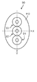
- FIG. 4A and 4B show a schematic cross-sectional view of the fiber bundle
- FIG. 5 shows the cross-sectional structure and the refractive index distribution of the first optical fiber.
- FIG. 4A shows a case where the outer shape of the cross section of the fiber bundle is circular
- FIG. 4B shows a case where the outer shape of the cross section of the fiber bundle is elliptical.
- the second optical fiber and the third optical fibers 92 and 93 also have the same structure as shown in FIG.
- the first to third fibers 91 to 93 are arranged so that their optical axes coincide with the Y axis.
- the first optical member 51 When performing welding, for example, when the laser light LB is incident on the first optical fiber 91, the first optical member 51 is first arranged at the above-mentioned first position in a state where the laser oscillation is not performed.
- the first motor 71 When laser oscillation is performed and the laser light LB is emitted from the laser resonator, the first motor 71 is rotated by a control signal from the controller 80 in the direction A shown in FIG. 2 at a predetermined angle, and the first motor 71 is rotated.
- the first optical member 51 tilts at a predetermined angle in the YZ plane about the holder 60a in response to the rotation of the 71.
- the angle between the light incident surface of the first optical member 51 and the optical axis of the laser light LB changes, and the optical path of the laser light LB is changed inside the first optical member 51.
- the laser beam LB whose optical axis has been changed is incident on the incident end face of the first optical fiber 91.
- the tilt angle of the first optical member 51 is adjusted so that the laser beam LB is incident on the core 91a of the first optical fiber 91.
- the refractive index of the core 91a is higher than that of the first clad 91b, and the incident laser beam LB is confined in the core 91a and propagates in the first optical fiber 91.
- the first motor 71 rotates the first optical member 51 at a different angle. By doing so, the laser beam LB moves in the Y direction by a predetermined distance at the incident end face of the bundle fiber 90 and is incident on the core of the second optical fiber 92. Further, when the laser beam LB is incident on the third optical fiber 93, the first motor 71 rotates the first optical member 51 at a different angle. By doing so, the laser beam LB moves in the Y direction by a predetermined distance at the incident end face of the bundle fiber 90 and is incident on the core of the third optical fiber 93.
- the first to third optical fibers 91 included in the fiber bundle 90 are tilted. From 93 to 93, an optical fiber to which the laser beam LB is incident can be selected. Further, this makes it possible to select the laser light emitting head from which the laser light LB is emitted.
- the selection of the optical fiber into which the laser beam LB is incident, the switching timing of the laser beam LB incident, and the like are performed according to the control signal from the controller 80 based on the laser processing program.
- the first optical member 51 may be moved out of the optical path. Needless to say, it can be left as it is.
- the laser light LB is inserted into the first to third optical fibers 91 to 93 in order has been described, but this is for convenience and does not have to be in this order. Further, when the position of the fiber bundle 90 is determined in advance so that the laser beam LB enters the core of the second fiber 92 located at the center position of the fiber bundle 90 while the first optical member 51 is moved out of the optical path, the second When the laser beam LB is inserted only into the fiber 92, it is possible to keep the first optical member 51 moved out of the optical path.
- the laser oscillator 10 that generates the laser light LB and the first to third optical fibers 91 to 93 are bundled so as to have a predetermined arrangement relationship.
- the fiber bundle 90, the beam control mechanism 20 provided in the laser oscillator 10, and the first to third optical fibers are attached to the respective emission ends and irradiate the laser beam LB toward the workpieces 201 to 203, respectively.
- the first to third laser light emitting heads 121 to 123 are provided at least.
- the beam control mechanism 20 is provided on the optical path of the condensing lens 30 that receives the laser light LB and condenses it at a predetermined magnification, and the laser light LB that travels between the condensing lens 30 and the incident end face of the fiber bundle 90. It has at least a first optical path changing mechanism 41 for changing the optical path of the laser beam LB and a controller 80 for controlling the operation of the first optical path changing mechanism 41.
- the beam control mechanism 20 causes a laser beam LB to be incident on an optical fiber selected from the first to third optical fibers 91 to 93, for example, the first optical fiber, and the first laser attached to the first optical fiber 91.
- the laser light LB is emitted from the light emitting head 121.
- the laser processing apparatus 1000 By using the laser processing apparatus 1000 as shown in FIG. 1 and appropriately switching the laser light emitting head from which the laser light LB is emitted, a large amount of workpieces are often laser-processed in factories and the like. In this case, by sharing the laser oscillator 10 connected to the plurality of laser light emitting heads, the laser processing apparatus 1000 can be miniaturized and the area can be reduced.
- Such a laser processing device 1000 by providing the above-mentioned beam control mechanism 20 in the laser oscillator 10, it is possible to easily and quickly switch the laser light emitting head from which the laser light LB is emitted. Further, this can reduce the man-hours and time required for switching the laser light emitting head, and can reduce the cost of laser processing.
- the first optical member 51 includes a predetermined position (first position) on the optical path of the laser beam LB traveling between the condenser lens 30 and the incident end faces of the first to third optical fibers 91 to 93 and the outside of the optical path. It is provided so that it can be moved between.
- the optical path of the laser beam LB can be easily changed. It can.
- Patent Document 2 even if the optical member is arranged in front of the condenser lens 30, the laser beam LB after passing through the condenser lens 30 is imaged at the focal position. The optical path cannot be changed.
- the laser beam LB is emitted by arranging the parallel flat plate-shaped first optical member 51 at the above-mentioned first position and tilting the first optical member 51 by the first motor 71.
- the optical fiber and, by extension, the laser light emitting head can be switched easily and at high speed.
- the thickness of the first optical member 51 is about 1 mm to several mm, and because it is installed in a narrow position between the condenser lens 30 and the fiber bundle 90 through which the focused laser light LB passes.
- the required size is small, and the first motor 71 makes it easy to tilt at high speed. In addition, it becomes easy to reciprocate within a predetermined angle range. As a result, the laser light emitting head from which the laser light LB is emitted can be switched at high speed.
- the laser beam LB is converted into parallel light before being incident on the condenser lens 30.
- the optical path and the optical axis of the laser beam LB emitted from the condenser lens 30 become constant, so that the optical path of the laser beam LB can be easily changed by the first optical path changing mechanism 41.
- a configuration in which three optical fibers 91 to 93 are bundled in a fiber bundle 90 is shown, but the present invention is not particularly limited to this.
- they may be provided adjacent to the optical fiber 93 or the optical fiber 91 in the Y-axis direction.
- FIG. 6 shows a schematic cross-sectional view of another fiber bundle
- FIG. 7 shows a schematic cross-sectional view of yet another fiber bundle.
- the number of optical members and motors connected thereto is increased according to the number of optical fibers included in the fiber bundle 90, so that the configuration shown in FIGS. 6 and 7 is configured.
- the laser light LB generated by the laser oscillator 10 can be incident on any of the optical fibers 91 to 103 included in each.
- the number of laser light emitting heads connected to one laser oscillator 10 can be increased, and the laser processing apparatus 1000 can be further miniaturized and the area can be reduced.
- the man-hours and time required to switch the laser light emitting head, and eventually the cost of laser processing can be further reduced.
- the first optical fiber 91 is arranged at the center as shown in FIGS. 6 and 7, and other light is used. It is preferable to arrange the fibers concentrically from the center. Further, in this case, it is preferable that the angles formed by the centers of the optical fibers adjacent to each other on the concentric circumference and the centers of the first optical fibers 91 are substantially the same. As shown in FIG. 7, there may be a plurality of concentric circles in which the optical fibers are arranged. Further, in this case, it is preferable to arrange the optical fibers at positions facing each other with the first optical fiber 91 interposed therebetween. As shown in FIGS.
- each optical fiber can be arranged at symmetrical positions around the first optical fiber 91, so that the operation of the optical path changing mechanism can be simplified and the optical fiber to which the laser light LB is incident can be switched. It can be done easily.
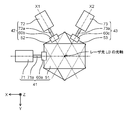
- ⁇ Modification example 1> 8 to 9 show a schematic view of the beam control mechanism according to this modification as viewed from the Z direction.
- FIGS. 8 to 9 the same parts as those in the first embodiment are designated by the same reference numerals, and detailed description thereof will be omitted.
- the second to third optical path changing mechanisms 42 to 43 are added in addition to the first optical path changing mechanism 41 to the configuration examples shown in FIGS. 2 to 3.
- the extending direction of the output shaft 71a of the first motor 71 of the first optical path changing mechanism 41 coincides with the X direction, but the output shafts 72a of the second to third motors 72 to 73 of the second to third optical path changing mechanisms 42 to 43
- the extending direction of ⁇ 73a coincides with the X1 axis and the X2 axis forming 60 degrees with the clockwise direction or the counterclockwise direction in the X direction in the XY plane.
- the second to third optical members are at the same position (first position) on the optical path of the laser beam LB traveling between the condenser lens 30 and the incident end surface of the fiber bundle 90. ) And the outside of the optical path are movable.
- FIG. 8 is a schematic view when the first optical member 51 is on the optical path of the laser beam LB and the second to third optical members 52 to 53 are outside the optical path.
- FIG. 9 is a schematic view when the first to third optical members 51 to 53 are all on the optical path of the laser light LB, but in reality, the first to third optical members 51 to 53 are Not all are on the optical path of the laser beam LB.
- the controller 80 selects any one of the first to third optical members 51 to 53, and arranges the selected one on the optical path of the laser beam LB.
- the controller 80 arranges the two unselected ones outside the optical path.
- the first optical member 51 When the laser beam LB is incident on the optical fiber on the Y-axis during the welding process, the first optical member 51 is first arranged at the above-mentioned first position in a state where the laser oscillation is not performed.
- the first motor 71 is controlled so that the laser beam LB is incident on the optical fiber on the Y axis, and the laser resonator is oscillated to perform welding.
- the laser oscillation is stopped and the first optical member 51 is moved out of the optical path.
- the third optical member 53 is arranged at the above-mentioned first position, and the laser beam LB is incident on the optical fiber on the X1 axis.
- the third motor 73 may be controlled.
- the second optical member 52 When welding is performed by incidenting the laser beam LB on the optical fiber on the X2 axis, the second optical member 52 is arranged at the above-mentioned first position, and the laser beam LB is incident on the optical fiber on the X2 axis.
- the second motor 72 may be controlled.
- the first to third optical members 51 to 53 are provided at the same position (first position) on the optical path of the laser beam LB traveling between the condenser lens 30 and the incident end surface of the fiber bundle 90. However, they may be provided at different positions. An example thereof will be described with reference to FIG.
- FIG. 10 shows a schematic view of the beam control mechanism according to the second modification as viewed from the X direction.
- the same parts as those in the first embodiment or the first modification are designated by the same reference numerals, and detailed description thereof will be omitted.
- the configuration according to the present modification is different from the configuration shown in the modification 1 in that the first to third optical members 51 to 53 are arranged at different positions on the optical path of the laser beam LB. Specifically, when the first optical member 51 is arranged on the optical path of the laser beam LB, it is arranged at the same position as in the first embodiment, and the second optical member 52 is arranged at a condenser lens 30 rather than the first position. The third optical member 53 is arranged at a position closer to the condenser lens 30 than the second optical member 52.
- the first to third motors 71 to 73 are also arranged at positions at predetermined intervals along the optical axis of the laser light LB.
- the beam control mechanism 20 may be configured in this way.
- the second optical member 52 or the third optical member 53 is placed at the first position of the laser beam LB. Can be moved.
- the second optical material 52 or the third optical material 53 can be moved to a predetermined position of the laser light LB while moving the first optical member 51 out of the optical path of the laser light LB. .. Therefore, the switching time before irradiating another optical fiber with the laser beam LB can be shortened.
- FIG. 11 shows the cross-sectional structure and the refractive index distribution of the first optical fiber according to the present embodiment.
- each of the optical fibers included in the fiber bundle 90 is a so-called multi-clad fiber.
- the first optical fiber 91 includes a core 91a, a first clad 91b provided coaxially with the core 91a on the outer peripheral side of the core 91a, and a core 91a on the outer peripheral side of the first clad 91b. It has a second clad 91c provided coaxially with the cable.
- the core 91a, the first clad 91b, and the second clad 91c are mainly composed of quartz, and as shown in FIG. 11, the core 91a has the highest refractive index, and the first clad 91b and the second clad 91c are refracted in this order. The rate is low.
- the refractive index of the first clad 91b and the second clad 91c may be adjusted by doping different types or concentrations of substances that can both reduce the refractive index.
- the index of refraction of the core 91a may also be adjusted by doping different types or concentrations of substances that can increase the index of refraction.
- the laser beam LB incident on the core 91a at a predetermined angle can propagate in the core 91a without entering the first clad 91b.
- the laser beam LB incident on the first clad 91b at a predetermined angle can propagate in the first clad 91b without entering the second clad 91c.
- the structure shown in FIG. 10 is merely an example, and the refractive indexes of the core 91a, the first clad 91b, and the second clad 91c are necessarily different. It is not necessary to have.
- the core 91a, the first clad 91b, and the second clad 91c have the same refractive index N1, and between the core 91a and the first clad 91b, and between the first clad 91b and the second clad 91c.
- a thin layer having a refractive index N2 (N2 ⁇ N1) may be provided.
- the laser beam LB incident on the core 91a at a predetermined angle can propagate in the core 91a without entering the first clad 91b, but is incident on the first clad 91b at a predetermined angle.
- the resulting laser beam LB can propagate in the first clad 91b without entering the second clad 91c.
- the main component of the layer having a refractive index N2 is quartz, but a substance capable of lowering the refractive index may be doped.
- the laser beam LB incident on the first optical fiber 91 propagates through the core 91a and / or the first clad 91b and reaches the exit end of the first optical fiber 91.
- a film or a resin-based protective layer that mechanically protects the first optical fiber 91 is provided on the outer peripheral surface of the second clad 91c.
- the laser light LB at the incident end face of the first optical fiber 91 The incident position can be changed. This will be described further.
- FIG. 12 shows the relationship between the incident position of the laser light on the incident end face of the first optical fiber and the power ratio of the laser light transmitted inside the core
- FIG. 13 shows the relationship between the laser light on the incident end face of the first optical fiber.
- the relationship between the incident position and the beam profile of the laser beam emitted from the first laser beam emitting head is shown.
- the beam profile shown in FIG. 13 corresponds to the power distribution of the laser light LB emitted from the first laser light emitting head 121 and imaged at the focal position.
- the beam profile shown in FIG. 13 also corresponds to the power distribution of the laser beam LB emitted from the emission end of the first optical fiber 91.
- the laser light LB When the incident position of the laser light LB is I shown in FIG. 12, the laser light LB is 100% incident in the core 91a, and the beam profile of the laser light LB has a single peak shape with a narrow half-value width as shown in FIG. (Incident position of laser beam LB: I).
- 100% of the laser beam LB is incident on the core 91a until the incident position of the laser beam LB approaches the position II shown in FIG. 12 from the core 91a, and the beam profile is single peak. Maintained in shape.
- the beam profile changes so as to include a single peak-shaped portion and a terrace-shaped portion having a wide half-value width formed on both sides thereof (incident position of laser beam LB: ⁇ III). ).
- the former corresponds to the laser beam LB incident in the core 91a
- the latter corresponds to the laser beam LB transmitted in the first clad 91b.
- the peak value of the single peak-shaped portion decreases.
- the power ratio of the laser light LB incident in the core 91a becomes equal to the power ratio of the laser light LB incident in the first clad 91b.
- the cross-sectional area of the core 91a is equal to the cross-sectional area of the first clad 91b, the peak value of the single peak-shaped portion and the peak value of the terrace-shaped portion of the beam profile coincide with each other, which is shown in FIG.
- the beam profile of the entire laser beam LB has a single peak shape, its peak value is lower and the half-value width is larger than that in the case where the laser beam LB is incident only in the core 91a (laser beam).
- Incident position of LB III
- the beam profile has a single-peaked portion and a terrace-like shape having a wide half-value width formed on both sides thereof, as shown in FIG. The shape is such that it includes the portion of (incident position of laser beam LB: ⁇ III).
- the beam profile becomes bimodal as shown in FIG. 13 (incident position of the laser beam LB: ⁇ IV).
- the incident position of the laser beam LB moves away from the core 91a (between III and IV shown in FIG. 12), the power of the laser beam LB incident in the core 91a decreases and is incident in the first clad 91b.
- the power ratio of the laser beam LB to be generated becomes high.
- the peak value of the portion of the beam profile corresponding to the component transmitted in the core 91a decreases, and the peak value of the portion corresponding to the component transmitted in the first clad 91b decreases.
- the value increases and the beam profile becomes bimodal (incident position of laser beam LB: ⁇ IV).
- the peak value in the bimodal beam profile is lower than the peak value in the monomodal beam profile obtained when the incident position of the laser beam LB is I shown in FIG.
- the incident position of the laser is further separated from the core 91a (between IV and V shown in FIG. 12)
- the power of the laser light LB incident in the core 91a becomes 0%
- the laser The light LB is 100% incident in the first clad 91b.
- the incident position of the laser beam LB When the incident position of the laser beam LB is completely within the second clad 91c (positions V to VI shown in FIG. 12), as shown in FIG. 13, it corresponds to the component transmitted into the core 91a of the beam profile.
- the peak value of the portion is reduced to 0%, the peak value of the portion corresponding to the component transmitted in the first clad 91b is maximized, and the beam profile is bimodal with the highest peak value (laser light LB).
- Incident position In the case of V to VI).
- the peak value in the bimodal beam profile is lower than the peak value in the monomodal beam profile obtained when the incident position of the laser beam LB is I shown in FIG.
- the beam control mechanism 20 is configured to switch the power distribution of the laser light LB emitted from the first laser light emitting head 121 during the laser processing of the work 201.
- the processed shape of the work 201 for example, the welded shape can be made good. This will be described further.
- FIG. 14 shows a schematic cross-sectional view of the welded portion of the work for comparison
- FIG. 15 shows a schematic cross-sectional view of the welded portion of the work according to the present embodiment.
- the portion irradiated with the laser beam is heated to cause melting, and a molten pool is formed. Further, in the portion irradiated with the laser beam, the material constituting the work evaporates on the surface, and the reaction force forms a keyhole inside the work.
- the laser light LB is transmitted only into the core 91a of the first optical fiber 91 and is irradiated from the first laser light emitting head 121 toward the work 201, and the laser light LB at the welded portion
- the power density is high, and the spot diameter of the irradiated laser beam LB is small.
- the work 201 is likely to be blended and the keyhole 220 is deepened, while the opening 221 of the keyhole 220 is not so widened, and as shown in FIG. 14, the constricted portion 222 is inside the keyhole 220. May occur. Further, when the constricted portion 222 is closed, air bubbles 223 remain inside the work 201. Further, when the closed constricted portion 222 becomes the keyhole 220 again, if the molten metal suddenly ejects from the inside of the keyhole 220 toward the surface, the spatter 212 adheres to the surface of the work 201 or the molten pool 210 The surface of the surface is rippling.
- the molten pool 210 is rapidly cooled and solidified after passing through the laser beam LB, when such a wave is generated, the unevenness 211 (on the surface of the work 201 behind the molten pool 210 along the traveling direction of laser welding) The rear vibrating portion 211) is generated.
- this wave is reflected and bounces off at the boundary between the molten pool 210 and the solidified part.
- this reflected wave reaches the keyhole 220, it flows so as to fill the keyhole 220.
- the molten metal that has flowed in is rapidly heated by the laser beam LB, and suddenly generates metal vapor, so that the columnar shape of the keyhole 220 is disturbed.
- the irregular shape of the keyhole 220, the generation of air bubbles 223, and the spatter 212 and unevenness 211 generated on the surface of the work 201, which have been described above, have been factors that deteriorate the welding quality.
- the power distribution of the laser beam LB emitted from the first laser beam emitting head 121 toward the work 201 can be changed by using the beam control mechanism 20. Therefore, for example, by adjusting the tilt angle of the first optical member 51, the power of the laser light LB transmitted in the core 91a of the first optical fiber 91 and the laser light LB transmitted in the first clad 91b By changing the ratio, the laser beam LB having a beam profile as shown in FIG. 15 can be irradiated toward the work 201.
- the desired penetration depth D can be obtained by the laser beam LB emitted from the core 91a.
- the laser beam LB emitted from the first clad 91b can widen the opening 221 of the keyhole 220 as compared with the case shown in FIG.
- the inner wall surface of the keyhole 220 is also irradiated with the laser beam LB, and the laser beam LB is absorbed by the work 201 in the process of the laser beam LB reaching the inside of the keyhole 220 by multiple reflection.
- the welding quality can be improved by switching the power distribution of the laser beam LB emitted from the first laser beam emitting head 121 during laser welding.
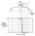
- FIG. 16 shows the welding sequence of the work, and the molten pool 210 is not formed in the work 201 immediately after the start of welding.
- the controller 80 drives the first motor 71 to incident the laser beam LB only on the core 91a.
- the spot diameter of the laser beam LB irradiated to the work 201 is reduced, and the power density of the laser beam LB at the welded portion is increased (first irradiation step).
- the molten pool 210 and the keyhole 220 it is desired to suppress the formation of the constricted portion 222 and the like as described above.
- the controller 80 drives the first motor 71 to inject the laser beam LB into the core 91a and the first clad 91b.
- the opening 221 of the keyhole 220 is widened, and the desired penetration depth D is obtained (second irradiation step).
- the second laser light irradiation head 122 and the third laser light irradiation head 123 are also used, the workpieces 202 and 203 are laser welded in the same sequence, respectively.
- the notation of switching the laser light LB to the second to third laser light irradiation heads 122 to 123 is omitted.
- the molten pool 210 and the keyhole 220 can be reliably formed in the workpieces 201 to 203, and the generation of air bubbles 223 inside the workpieces 201 to 203 and surface irregularities 211 and the like can be suppressed. Therefore, the welding quality can be improved.
- the beam control mechanism 20 is operated according to the material of the works 201 to 203 and / or the shape of the laser processing target portion in the works 201 to 203, and the laser light emitting head is used from any of the plurality of laser light emitting heads.
- the workpieces 201 to 203 having various materials and shapes can be laser-machined, and the processing quality thereof can be improved.
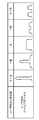
- FIG. 17 shows a periodic change in the beam profile of the laser beam.
- the first optical fiber 91 in the present embodiment is a multi-clad fiber as shown in the second embodiment.
- the first optical member 51 by reciprocating the first motor 71 within a predetermined angle range, the first optical member 51 also reciprocates within a predetermined angle range accordingly. That is, the beam control mechanism 20 is configured to periodically switch the power distribution of the laser light LB emitted from the first laser light emitting head 121 during the laser processing of the work 201.
- the rotation frequency of the first optical member 51 is set to about several Hz to several kHz.
- the second motor 72 and the third motor 73 can also reciprocate within an angle range, and accordingly, the second optical member 52 and the third optical member 53 are also predetermined. It reciprocates within an angular range.
- the power distribution of the laser light LB emitted from the emission end of the first laser light emission head 121 changes periodically. Specifically, the beam profile having a single peak-like peak is continuously changed to a beam profile having a bimodal peak, and the change is periodically repeated. Further, the rotation frequency of the first optical member 51 corresponds to the frequency at which the power distribution of the laser beam LB changes.
- the molten pool 210 and the keyhole 220 are surely formed in the work 201, the keyhole 220 is prevented from becoming too narrow, and the generation of air bubbles 223 and spatter 212 is suppressed.
- Laser welding can be performed.
- the power distribution of the laser beam LB at a predetermined frequency, in this case, a frequency substantially equal to the natural vibration frequency of the keyhole 220 formed in the work 201, behind the molten pool 210 described above.
- the unevenness 211 to be formed can be reduced, and the shape disorder of the keyhole 220 can be effectively suppressed. This will be described further.
- the keyhole 220 In the process of sequentially forming the molten pool 210 along the direction of laser welding, the keyhole 220 also moves along the direction of laser welding. At this time, the keyhole 220 vibrates repeatedly in the radial direction and / or the depth direction in the radial direction and / or the depth direction at a natural vibration frequency (hereinafter, simply referred to as a natural vibration frequency). ..
- the natural vibration frequency is a value determined by the size of the molten pool 210, the viscosity of the constituent metal of the molten work at the time of melting, and the like, and is estimated to be about several Hz to several kHz in many cases.
- the shape of the keyhole 220 is stabilized and the constricted portion 222 is generated inside the work 201.
- the generation of bubble 223 can be suppressed.
- the unevenness 211 formed behind the molten pool 210 can be reduced.
- the method of changing the power distribution of the laser beam LB periodically and continuously as described above is particularly effective for thick plate welding. This is because the thicker the plate, the deeper the required penetration, and the deeper the keyhole 220 to achieve it, so there is a probability that welding defects will occur due to the instability of the keyhole 220 (for example, constriction). This is because it becomes expensive.
- the first optical fiber 91 in this modification is a multi-clad fiber as shown in the second embodiment.
- FIG. 18 shows a welding sequence of the work according to the present modification, and the work 201 has a shape having a thin plate portion and a thick plate portion continuous thereto.
- the thickness of the thick plate portion is thicker than that of the thin plate portion.
- the work 201 is irradiated with the laser beam LB in the sequence shown in FIG.
- the penetration depth D does not have to be too deep. Therefore, after the work 201 is irradiated with the laser beam LB with a beam profile having a single peak at the start of welding to form the molten pool 210 and the keyhole 220, the power distribution of the laser beam LB becomes broad. To prevent the formation of the constricted portion 222 in the keyhole 220.
- the work 201 is irradiated with the laser beam LB in the sequence shown in FIG. That is, the laser beam LB is irradiated toward the work 201 while periodically changing the power distribution of the laser beam LB at the natural vibration frequency.
- the thin plate portion may be welded while the power distribution of the laser beam LB is fixed so as to be broad from the beginning.
- the first optical member 51 is configured to be movable inside and outside the optical path of the laser beam LB, but the present invention is not particularly limited to this, and the first optical member 51 may be fixedly arranged in the optical path of the laser beam LB. .. However, even in that case, the first optical member 51 can rotate around the axis of the output shaft 71a. In this case, the second optical member 52 or the third optical member 53 is placed outside the optical path of the laser beam LB. Similarly, the second optical member 52 and the third optical member 53 may be fixed in the optical path of the laser beam LB.
- the second optical member 52 and the third optical member 53 can rotate around the axis of the output shaft 72a and the axis of the output shaft 73a, respectively.
- the remaining two optical members are placed outside the optical path of the laser beam LB.
- the multi-clad fiber having the structure shown in FIG. 11 has been described as an example in the second and third embodiments including the third modification, other structures may be used.
- one or more clads may be provided on the outer peripheral side of the second clad 91c.
- the refractive index of the clad provided on the outside of the second clad 91c may be gradually lowered.
- the clad to which the laser beam LB can be incident may be up to the clad excluding the outermost clad.
- a film or a resin-based protective layer that mechanically protects the fiber is provided outside the outermost clad.
- the output and wavelength of the laser beam LB can be appropriately changed depending on the material and shape of the work or the processing content.
- actuators other than the first to third motors 71 to 73 for example, a piezoelectric actuator or the like may be used.
- the so-called keyhole type laser welding in which the keyhole 220 is formed in the molten pool 210 has been described as an example, but the material and shape of the work, the required penetration depth D, and the like.
- the type of laser welding can be appropriately selected depending on the width of the welding bead and the like.
- the above-mentioned laser processing apparatus 1000 and welding sequence can be applied not only to laser welding but also to laser cutting.
- the laser processing device of the present invention can easily switch the laser light emitting head from which the laser light is emitted, and is useful as a laser processing device capable of processing a large amount of workpieces.
- Laser oscillator 20 Beam control mechanism 30 Condensing lens 41 to 43 First to third optical path changing mechanisms 51 to 53 First to third optical members 60a, 60b, 60c Holders 71 to 73 First to third motor 80 Controller 90 Fiber bundles 91 to 93 1st to 3rd optical fibers 91a Core 91b 1st clad 91c 2nd clad 121 to 123 1st to 3rd laser light emitting heads 131 to 133 1st to 3rd manipulators 201 to 203 Work 210 Molten pond 220 Keyhole 221 Opening 1000 Laser processing equipment LB Laser light
Landscapes
- Physics & Mathematics (AREA)
- Optics & Photonics (AREA)
- Engineering & Computer Science (AREA)
- Plasma & Fusion (AREA)
- Mechanical Engineering (AREA)
- Robotics (AREA)
- Laser Beam Processing (AREA)
Abstract
This laser machining device comprises a laser oscillator, 1st-3rd optical fibers, a beam control mechanism, and 1st-3rd laser beam projection heads that are respectively attached to the 1st-3rd optical fibers. The beam control mechanism includes: a focusing lens; 1st-3rd light path changing mechanisms that are provided on the light path of a laser beam LB after the same has passed through the focusing lens; and a controller that controls the operation of the 1st-3rd light path changing mechanisms. The beam control mechanism causes a laser beam to be projected from the first laser projection head via the first optical fiber, which was selected.
Description
本発明はレーザ加工装置及びそれを用いたレーザ加工方法に関する。
The present invention relates to a laser processing apparatus and a laser processing method using the laser processing apparatus.
近年、複数のレーザ光出射ヘッドを有するレーザ加工装置が提案されている。このようなレーザ加工装置は、1つのレーザ発振器に接続された複数の光ファイバと、複数の光ファイバのそれぞれに取り付けられたレーザ光出射ヘッドとを備える。また、このレーザ加工装置は、レーザ光が伝送される光ファイバを適宜切り替えて、レーザ光を、選択されたレーザ光出射ヘッドに伝送する。
In recent years, a laser processing device having a plurality of laser light emitting heads has been proposed. Such a laser processing apparatus includes a plurality of optical fibers connected to one laser oscillator, and a laser light emitting head attached to each of the plurality of optical fibers. Further, this laser processing apparatus appropriately switches the optical fiber to which the laser light is transmitted, and transmits the laser light to the selected laser light emitting head.
例えば、特許文献1は、レーザ光と光学的に結合可能な束状の複数の光ファイバにレーザ光を入射するレーザシステムを開示している。このレーザシステムは、レーザ光の光路上に配置されたリフレクタ又は集光レンズと、それらを動かすピエゾアクチュエータとを含む。ピエゾアクチュエータは、束状の複数の光ファイバにおけるレーザ光の入射位置を変化させることで、複数の光ファイバのうち、選択された光ファイバにレーザ光を入射させる。
For example, Patent Document 1 discloses a laser system in which a laser beam is incident on a plurality of bundled optical fibers that can be optically coupled to the laser beam. The laser system includes a reflector or condenser lens located on the optical path of the laser beam and a piezo actuator to move them. The piezo actuator causes the laser beam to be incident on a selected optical fiber among the plurality of optical fibers by changing the incident position of the laser beam on the plurality of bundled optical fibers.
一方、ワークの材質や形状に応じて、レーザ光のビーム品質を変化させてレーザ加工を行う技術が提案されてきている。
On the other hand, a technique for performing laser processing by changing the beam quality of the laser beam according to the material and shape of the work has been proposed.
特許文献1では、光ファイバはマルチクラッドファイバからなる。レーザシステムは、レーザ光の入射位置を調整することでレーザ光のビームプロファイルを変化させている。
In Patent Document 1, the optical fiber is made of a multi-clad fiber. The laser system changes the beam profile of the laser beam by adjusting the incident position of the laser beam.
また、特許文献2には、集光レンズの位置を移動させたり、レーザ光の光路上にくさび状の光学素子を挿入したりすることで、マルチクラッドファイバの入射端におけるレーザ光の入射位置を変化させる構成が提案されている。
Further, in Patent Document 2, by moving the position of the condenser lens or inserting a wedge-shaped optical element on the optical path of the laser beam, the incident position of the laser beam at the incident end of the multi-clad fiber can be determined. A variable configuration has been proposed.
しかし、特許文献1に開示された構成では、比較的大型の光学部品であるリフレクタや集光レンズをアクチュエータで動かすため、その応答性に問題があり、レーザ光の光路を高速に変更し、複数の光ファイバのうち選択された光ファイバに速やかにレーザ光を入射させることが難しかった。
However, in the configuration disclosed in Patent Document 1, since a reflector and a condenser lens, which are relatively large optical components, are moved by an actuator, there is a problem in their responsiveness, and the optical path of the laser beam is changed at high speed to obtain a plurality of laser beams. It was difficult to quickly inject the laser beam into the selected optical fiber among the optical fibers of the above.
また、特許文献2に開示されるように、集光レンズの位置を移動させてレーザ光の入射位置を変化させるのには、集光レンズを直線上にアクチュエータで動かす必要があるため、位置精度と応答性を両立させる上で問題があった。
Further, as disclosed in Patent Document 2, in order to move the position of the condenser lens and change the incident position of the laser beam, it is necessary to move the condenser lens in a straight line by an actuator, so that the position accuracy is correct. There was a problem in achieving both responsiveness and responsiveness.
本発明はかかる点に鑑みてなされたもので、その目的は、複数のレーザ光出射ヘッドが設けられたレーザ加工装置において、レーザ光が入射されるレーザ光出射ヘッドの切替えを簡便かつ高速で行うことのできるレーザ加工装置及びそれを用いたレーザ加工方法を提供することにある。
The present invention has been made in view of this point, and an object of the present invention is to easily and quickly switch the laser beam emitting head into which the laser beam is incident in a laser processing apparatus provided with a plurality of laser beam emitting heads. It is an object of the present invention to provide a laser processing apparatus capable of the above and a laser processing method using the same.
上記の目的を達成するため、本発明に係るレーザ加工装置は、レーザ光を発生させるレーザ発振器と、複数の光ファイバが所定の配置関係となるように束ねられてなるファイババンドルと、前記レーザ発振器に設けられたビーム制御機構と、前記複数の光ファイバのそれぞれの出射端に取付けられ、前記レーザ光をワークに向けて照射する複数のレーザ光出射ヘッドと、を少なくとも備え、前記ビーム制御機構は、前記レーザ光を受け取って所定の倍率で集光する集光レンズと、前記集光レンズと前記ファイババンドルの入射端面との間を進行する前記レーザ光の光路上に設けられ、前記レーザ光の光路を変更する複数の光路変更機構と、前記複数の光路変更機構の動作を制御するコントローラと、を少なくとも有し、前記ビーム制御機構は、前記複数の光ファイバのうち選択された一の光ファイバに前記レーザ光を入射させ、前記一の光ファイバに取付けられた前記レーザ光出射ヘッドから前記レーザ光を出射させることを特徴とする。
In order to achieve the above object, the laser processing apparatus according to the present invention includes a laser oscillator that generates laser light, a fiber bundle in which a plurality of optical fibers are bundled so as to have a predetermined arrangement relationship, and the laser oscillator. The beam control mechanism is provided with at least a beam control mechanism provided in the above and a plurality of laser light emitting heads attached to each emission end of the plurality of optical fibers and irradiating the laser light toward the work. A condensing lens that receives the laser light and condenses it at a predetermined magnification, and a condensing lens that travels between the condensing lens and the incident end face of the fiber bundle, and is provided on the optical path of the laser light. The beam control mechanism has at least a plurality of optical path changing mechanisms for changing the optical path and a controller for controlling the operation of the plurality of optical path changing mechanisms, and the beam control mechanism is one optical fiber selected from the plurality of optical fibers. It is characterized in that the laser beam is incident on the laser beam and the laser beam is emitted from the laser beam emitting head attached to the one optical fiber.
この構成によれば、レーザ光が出射されるレーザ光出射ヘッドの切り替えを簡便かつ高速に行うことができる。また、レーザ光出射ヘッドを切り替えるために要する工数や時間を低減でき、レーザ加工のコストを低減できる。
According to this configuration, it is possible to easily and quickly switch the laser light emitting head from which the laser light is emitted. Further, the man-hours and time required for switching the laser light emitting head can be reduced, and the cost of laser processing can be reduced.
本発明に係るレーザ加工方法は、前記レーザ加工装置を用いたレーザ加工方法であって、前記ワークに向けて第1のパワー分布を有する前記レーザ光を照射する第1照射ステップと、引き続き、前記ワークに向けて前記第1のパワー分布とは異なる第2のパワー分布を有する前記レーザ光を照射する第2照射ステップと、を少なくとも備えたことを特徴とする。
The laser processing method according to the present invention is a laser processing method using the laser processing apparatus, which comprises a first irradiation step of irradiating the work with the laser beam having a first power distribution, followed by the above-mentioned. It is characterized by including at least a second irradiation step of irradiating the laser beam having a second power distribution different from the first power distribution toward the work.
この方法によれば、溶接開始初期にワークに溶融池及びキーホールを確実に形成できるとともに、ワークの溶接品質を高められる。
According to this method, a molten pool and a keyhole can be surely formed in the work at the initial stage of welding, and the welding quality of the work can be improved.
本発明のレーザ加工装置によれば、レーザ光が出射されるレーザ光出射ヘッドの切り替えを簡便かつ高速に行うことができる。本発明のレーザ加工方法によれば、ワークの溶接品質を高められる。
According to the laser processing apparatus of the present invention, it is possible to easily and quickly switch the laser light emitting head from which the laser light is emitted. According to the laser processing method of the present invention, the welding quality of the workpiece can be improved.
以下、本発明の実施形態を図面に基づいて詳細に説明する。以下の好ましい実施形態の説明は、本質的に例示に過ぎず、本発明、その適用物或いはその用途を制限することを意図するものでは全くない。
Hereinafter, embodiments of the present invention will be described in detail with reference to the drawings. The following description of preferred embodiments is merely exemplary and is not intended to limit the present invention, its applications or its uses.
(実施形態1)
[レーザ加工装置の構成]
図1は、本実施形態に係るレーザ加工装置の構成の模式図を示し、レーザ加工装置1000は、レーザ発振器10とビーム制御機構20とコントローラ80とファイババンドル90と第1~第3レーザ光出射ヘッド121~123と第1~第3マニピュレータ131~133とを備えている。 (Embodiment 1)
[Construction of laser processing equipment]
FIG. 1 shows a schematic diagram of the configuration of the laser processing apparatus according to the present embodiment, and thelaser processing apparatus 1000 includes a laser oscillator 10, a beam control mechanism 20, a controller 80, a fiber bundle 90, and first to third laser light emission. The heads 121 to 123 and the first to third manipulators 131 to 133 are provided.
[レーザ加工装置の構成]
図1は、本実施形態に係るレーザ加工装置の構成の模式図を示し、レーザ加工装置1000は、レーザ発振器10とビーム制御機構20とコントローラ80とファイババンドル90と第1~第3レーザ光出射ヘッド121~123と第1~第3マニピュレータ131~133とを備えている。 (Embodiment 1)
[Construction of laser processing equipment]
FIG. 1 shows a schematic diagram of the configuration of the laser processing apparatus according to the present embodiment, and the
レーザ発振器10は、図示しない電源から電力の供給を受けてレーザ光LBを発生させるレーザ光源である。なお、レーザ発振器10は、単一のレーザ光源で構成されていてもよいし、複数のレーザモジュールで構成されていてもよい。後者の場合は、複数のレーザモジュールからそれぞれ出射されたレーザ光を結合してレーザ光LBとして出射する。
The laser oscillator 10 is a laser light source that generates laser light LB by receiving electric power from a power source (not shown). The laser oscillator 10 may be composed of a single laser light source or a plurality of laser modules. In the latter case, the laser light emitted from each of the plurality of laser modules is combined and emitted as the laser light LB.
ビーム制御機構20は、レーザ発振器10に設けられており、レーザ光LBをファイババンドル90のうちの選択された光ファイバに伝送する。ビーム制御機構20の構成及び動作については後で述べる。なお、ビーム制御機構20は、光ファイバの出射端から出射されるレーザ光LBのパワー分布を制御することも可能であるが、これについても後で述べる。
The beam control mechanism 20 is provided in the laser oscillator 10 and transmits the laser light LB to the selected optical fiber in the fiber bundle 90. The configuration and operation of the beam control mechanism 20 will be described later. The beam control mechanism 20 can also control the power distribution of the laser beam LB emitted from the exit end of the optical fiber, which will also be described later.
ファイババンドル90は、第1~第3光ファイバ91~93が束ねられてなる光学部品である。第1光ファイバ91は、コア91aと、コア91aの外周側にコア91aと同軸に設けられた第1クラッド91bとを有している(図5参照)。第2及び第3光ファイバ92,93も同様に、コアと第1クラッド(いずれも図示せず)を有している。なお、図示しないが、第1クラッド91bの外周面には光ファイバを機械的に保護する皮膜または樹脂系の保護層が設けられている。また、第1~第3光ファイバ91~93は、束ねられた状態で樹脂等からなる保護部材110によって覆われ、互いの配置関係が固定されている(図4A,4B参照)。
The fiber bundle 90 is an optical component in which the first to third optical fibers 91 to 93 are bundled. The first optical fiber 91 has a core 91a and a first clad 91b provided coaxially with the core 91a on the outer peripheral side of the core 91a (see FIG. 5). The second and third optical fibers 92 and 93 also have a core and a first cladding (neither shown). Although not shown, a film or a resin-based protective layer that mechanically protects the optical fiber is provided on the outer peripheral surface of the first clad 91b. Further, the first to third optical fibers 91 to 93 are covered with a protective member 110 made of resin or the like in a bundled state, and the arrangement relationship with each other is fixed (see FIGS. 4A and 4B).
第1~第3レーザ光出射ヘッド121~123のそれぞれは、対応する光ファイバの出射端に取付けられており、光ファイバで伝送されたレーザ光LBをワーク201~203に向けて照射する。ワーク201~203がレーザ光LBによりレーザ加工される。なお、第1~第3レーザ光出射ヘッド121~123の内部には、それぞれ図示しない光学部品、例えば、コリメータレンズや集光レンズや保護ガラス等が配設されている。
Each of the first to third laser light emitting heads 121 to 123 is attached to the emitting end of the corresponding optical fiber, and irradiates the laser light LB transmitted by the optical fiber toward the workpieces 201 to 203. The works 201 to 203 are laser-machined by the laser beam LB. Optical components (not shown) such as a collimator lens, a condenser lens, and a protective glass are arranged inside the first to third laser light emitting heads 121 to 123, respectively.
コントローラ80は、レーザ発振器10のレーザ発振を制御する。具体的には、レーザ発振器10に接続された図示しない電源に対して出力電流やオン・オフ時間等の制御信号を供給することにより、レーザ発振制御を行う。
The controller 80 controls the laser oscillation of the laser oscillator 10. Specifically, laser oscillation control is performed by supplying control signals such as an output current and an on / off time to a power source (not shown) connected to the laser oscillator 10.
また、コントローラ80は、選択されたレーザ加工プログラムの内容に応じて、ビーム制御機構20に設けられた第1モータ71(図3A,3B参照)あるいは第2モータ72及び第3モータ73(図8参照)の駆動制御を行う。さらに、コントローラ80は、第1~第3マニピュレータ131~133の動作を制御する。なお、レーザ加工プログラムは、図示しない記憶部に保存されている。記憶部はコントローラ80の内部に設けられていてもよいし、コントローラ80の外部に設けられ、コントローラ80とデータのやり取りを可能に構成されていてもよい。なお、コントローラ80はビーム制御機構20の一部を構成している。
Further, the controller 80 is a first motor 71 (see FIGS. 3A and 3B) or a second motor 72 and a third motor 73 (FIG. 8) provided in the beam control mechanism 20 according to the content of the selected laser machining program. Refer to) for drive control. Further, the controller 80 controls the operation of the first to third manipulators 131 to 133. The laser machining program is stored in a storage unit (not shown). The storage unit may be provided inside the controller 80, or may be provided outside the controller 80 so that data can be exchanged with the controller 80. The controller 80 constitutes a part of the beam control mechanism 20.
第1~第3マニピュレータ131~133のそれぞれはコントローラ80に接続され、前述のレーザ加工プログラムに応じて所定の軌跡を描くように第1~第3レーザ光出射ヘッド121~123をそれぞれ移動させる。なお、第1~第3マニピュレータ131~133の動作を制御するコントローラを別に設けるようにしてもよい。
Each of the first to third manipulators 131 to 133 is connected to the controller 80, and the first to third laser light emitting heads 121 to 123 are moved so as to draw a predetermined trajectory according to the above-mentioned laser processing program. A controller for controlling the operation of the first to third manipulators 131 to 133 may be provided separately.
[ビーム制御機構の構成]
図2は、ビーム制御機構をX方向から見た模式図を、図3Aは、ビーム制御機構の要部をY方向から見た模式図を、図3Bは、ビーム制御機構の要部をZ方向から見た模式図をそれぞれ示す。なお、説明の便宜上、図2において、第1~第3光ファイバ91~93のうち第1光ファイバ91のみを示している。 [Structure of beam control mechanism]
FIG. 2 is a schematic view of the beam control mechanism viewed from the X direction, FIG. 3A is a schematic view of the main part of the beam control mechanism viewed from the Y direction, and FIG. 3B is a schematic view of the main part of the beam control mechanism in the Z direction. The schematic diagram seen from each is shown. For convenience of explanation, FIG. 2 shows only the firstoptical fiber 91 of the first to third optical fibers 91 to 93.
図2は、ビーム制御機構をX方向から見た模式図を、図3Aは、ビーム制御機構の要部をY方向から見た模式図を、図3Bは、ビーム制御機構の要部をZ方向から見た模式図をそれぞれ示す。なお、説明の便宜上、図2において、第1~第3光ファイバ91~93のうち第1光ファイバ91のみを示している。 [Structure of beam control mechanism]
FIG. 2 is a schematic view of the beam control mechanism viewed from the X direction, FIG. 3A is a schematic view of the main part of the beam control mechanism viewed from the Y direction, and FIG. 3B is a schematic view of the main part of the beam control mechanism in the Z direction. The schematic diagram seen from each is shown. For convenience of explanation, FIG. 2 shows only the first
また、本願明細書において、ビーム制御機構20の内部において、集光レンズ30に入射するまでのレーザ光LBの進行方向をZ方向と、第1モータ71の出力軸71aの延びる方向をX方向と、X方向及びZ方向をそれぞれ略直交する方向をY方向とそれぞれ呼ぶことがある。Z方向は、レーザ光LBの光軸の延びる方向と同方向である。X方向はZ方向と略直交している。また、第1モータ71の出力軸71aの軸線をX軸(第1軸)と呼ぶことがある。
Further, in the specification of the present application, inside the beam control mechanism 20, the traveling direction of the laser beam LB until it is incident on the condenser lens 30 is defined as the Z direction, and the extending direction of the output shaft 71a of the first motor 71 is defined as the X direction. , X direction and Z direction are referred to as Y direction, respectively. The Z direction is the same direction as the direction in which the optical axis of the laser beam LB extends. The X direction is substantially orthogonal to the Z direction. Further, the axis of the output shaft 71a of the first motor 71 may be referred to as an X axis (first axis).
なお、本願明細書において、「略直交」とは、各部品の組立公差を含んで直交しているという意味であり、厳密に直交していることまでを要求するものではない。同様に、「略同じ」または「略等しい」とは、各部品の製造公差や組立公差を含んで同じまたは等しいという意味であり、厳密に比較対象となる両者が同じか、または等しいことまでを要求するものではない。また、「略等しい」とは、推定値との比較において等しいことも意味するが、厳密に推定値と比較対象とが等しいことまでを要求するものではない。
In the specification of the present application, "substantially orthogonal" means that the parts are orthogonal to each other including the assembly tolerance, and does not require that the parts are strictly orthogonal. Similarly, "substantially the same" or "substantially equal" means the same or equal, including the manufacturing tolerances and assembly tolerances of each part, up to the fact that the two to be strictly compared are the same or equal. Not what you want. Further, "substantially equal" also means that they are equal in comparison with the estimated value, but does not require that the estimated value and the comparison target are exactly equal.
図2,3A,3Bに示すように、ビーム制御機構20は、集光レンズ30と第1光学部材51と第1モータ71とを有している。また、前述したように、ビーム制御機構20は、コントローラ80を有している。後で述べるように、第1モータ71と第1光学部材51とは、集光レンズ30で集光された後のレーザ光LBの光路を変更する第1光路変更機構41として機能する。
As shown in FIGS. 2, 3A and 3B, the beam control mechanism 20 includes a condenser lens 30, a first optical member 51, and a first motor 71. Further, as described above, the beam control mechanism 20 has a controller 80. As will be described later, the first motor 71 and the first optical member 51 function as a first optical path changing mechanism 41 that changes the optical path of the laser beam LB after being focused by the condenser lens 30.
レーザ光LBは、図示しない光学部品、例えば、コリメートレンズ等により平行光に変換された状態で集光レンズ30に入射される。集光レンズ30は所定の倍率でレーザ光LBを集光し、ファイババンドル90に向かわせる。
The laser light LB is incident on the condenser lens 30 in a state of being converted into parallel light by an optical component (not shown), for example, a collimated lens or the like. The condenser lens 30 collects the laser beam LB at a predetermined magnification and directs it toward the fiber bundle 90.
第1光学部材51は、レーザ光LBに対して透明な材質からなる平行平板状の部材である。第1光学部材51は、例えば、石英からなり、レーザ光LBの波長に対して1よりも大きい屈折率を有する。第1光学部材51は、入射したレーザ光に対する反射率をできるだけ下げるために、両面反射防止コーティイングを施されたものを使用してよい。反射防止コーティングを施した場合の反射率は、1%よりはるかに小さいことが望ましい。第1光学部材51は、集光レンズ30とファイババンドル90との間を進行するレーザ光LBの光路上に設けられている。第1光学部材51は、集光レンズ30とファイババンドル90の入射端面との間を進行するレーザ光LBの光路上の所定の位置(第1位置)と光路外との間を移動可能である。具体的には、集光レンズ30とファイババンドル90の入射端面との間を進行するレーザ光LBの光路上に第1光学部材51が配置される場合、レーザ光LBの光軸と直交する方向、例えば、X方向やY方向から見て、第1光学部材51が第1位置に配置される。第1位置に配置された第1光学部材51に、集光レンズ30で集光された後のレーザ光LBが入射される。一方、第1光学部材51が光路外に移動された場合、レーザ光LBが第1光学部材51のいかなる部分にも入射されないよう配置される。
The first optical member 51 is a parallel flat plate-shaped member made of a material transparent to the laser beam LB. The first optical member 51 is made of, for example, quartz and has a refractive index larger than 1 with respect to the wavelength of the laser beam LB. The first optical member 51 may be provided with double-sided antireflection coating in order to reduce the reflectance with respect to the incident laser light as much as possible. It is desirable that the reflectance with the antireflection coating is much less than 1%. The first optical member 51 is provided on the optical path of the laser beam LB traveling between the condenser lens 30 and the fiber bundle 90. The first optical member 51 is movable between a predetermined position (first position) on the optical path of the laser beam LB traveling between the condenser lens 30 and the incident end surface of the fiber bundle 90 and the outside of the optical path. .. Specifically, when the first optical member 51 is arranged on the optical path of the laser beam LB traveling between the condenser lens 30 and the incident end surface of the fiber bundle 90, the direction orthogonal to the optical axis of the laser beam LB. For example, the first optical member 51 is arranged at the first position when viewed from the X direction or the Y direction. The laser beam LB after being focused by the condenser lens 30 is incident on the first optical member 51 arranged at the first position. On the other hand, when the first optical member 51 is moved out of the optical path, the laser beam LB is arranged so as not to be incident on any part of the first optical member 51.
第1モータ71は出力軸71aを有しており、ホルダ60aを介して第1光学部材51に連結されている。例えば、第1モータ71を駆動させて、その出力軸71aがX軸回りに回転することで、第1光学部材51はホルダ60aを中心としてYZ平面内に回転する。また、第1モータ71は一方向のみに回転するのではなく、逆方向にも回転可能に構成されている。例えば、第1モータ71は、一方向、つまり、図2に示す方向Aのみに回転することもできるし、正逆両方向、つまり、図2に示す方向A及び方向Bのどちらにも回転することもできる。また、回転周波数は可変であり、溶接加工を行う際には、数Hz~数kHz程度の範囲で変化させることができる。また、後述するように、ビーム制御機構20を動作させる場合、第1モータ71は一方向に連続して回転動作を行うのではなく、所定の角度範囲を回転する。言い換えると、第1光学部材51はホルダ60aを中心として所定の角度で傾動する。また、第1モータ71は、第1光学部材51を設定された角度範囲で高速に往復回転させることができる。
The first motor 71 has an output shaft 71a and is connected to the first optical member 51 via a holder 60a. For example, by driving the first motor 71 and rotating its output shaft 71a around the X axis, the first optical member 51 rotates in the YZ plane about the holder 60a. Further, the first motor 71 is configured to be rotatable not only in one direction but also in the opposite direction. For example, the first motor 71 can rotate in only one direction, that is, the direction A shown in FIG. 2, or can rotate in both forward and reverse directions, that is, in both the forward and reverse directions, that is, the direction A and the direction B shown in FIG. You can also. Further, the rotation frequency is variable and can be changed in the range of several Hz to several kHz when welding is performed. Further, as will be described later, when the beam control mechanism 20 is operated, the first motor 71 does not continuously rotate in one direction, but rotates in a predetermined angle range. In other words, the first optical member 51 tilts at a predetermined angle about the holder 60a. In addition, the first motor 71 can reciprocate the first optical member 51 at a high speed within a set angle range.
なお、第1モータ71の出力軸71aの軸線は第1光学部材51が傾動される傾動軸に相当する。
The axis of the output shaft 71a of the first motor 71 corresponds to the tilting shaft on which the first optical member 51 is tilted.
また、第1モータ71はコントローラ80に接続され、コントローラ80からの制御信号によって駆動される。なお、第1モータ71は、図示しない移動機構によって、前述の第1位置と光路外との間を移動するように構成されている。第1モータ71に連結された第1光学部材51も同様に、第1位置と光路外との間を移動する。
Further, the first motor 71 is connected to the controller 80 and is driven by a control signal from the controller 80. The first motor 71 is configured to move between the above-mentioned first position and the outside of the optical path by a moving mechanism (not shown). Similarly, the first optical member 51 connected to the first motor 71 moves between the first position and the outside of the optical path.
なお、第1光学部材51のZ方向の厚さはそれぞれ1mmから数mm程度であるが、特にこれに限定されず、ファイババンドル90の端面におけるレーザ光LBの移動距離と第1モータ71の回転角度との関係で適宜別の値に変更しうる。当該厚さが数mm程度であると、また、集光レンズ30とファイババンドル90の入射端面との間の、集光されたレーザ光LBが通過する狭い位置に設置するため、その必要サイズが小さく、第1モータ71によって高速、例えば、数kHzの回転周波数で往復回転させることが容易となる。
The thickness of the first optical member 51 in the Z direction is about 1 mm to several mm, respectively, but is not particularly limited to this, and the moving distance of the laser beam LB and the rotation of the first motor 71 on the end face of the fiber bundle 90. It can be changed to another value as appropriate in relation to the angle. If the thickness is about several mm, and because it is installed in a narrow position between the condenser lens 30 and the incident end face of the fiber bundle 90 through which the focused laser light LB passes, the required size is required. It is small, and the first motor 71 facilitates reciprocating rotation at high speed, for example, at a rotation frequency of several kHz.
[選択された光ファイバへのレーザ光入射制御について]
次に、第1~第3光ファイバ91~93のうち選択された光ファイバにレーザ光LBを入射させる手順について説明する。 [Regarding the control of laser beam incident on the selected optical fiber]
Next, a procedure for injecting the laser beam LB into the optical fiber selected from the first to thirdoptical fibers 91 to 93 will be described.
次に、第1~第3光ファイバ91~93のうち選択された光ファイバにレーザ光LBを入射させる手順について説明する。 [Regarding the control of laser beam incident on the selected optical fiber]
Next, a procedure for injecting the laser beam LB into the optical fiber selected from the first to third
図4A,4Bは、ファイババンドルの断面模式図を、図5は、第1光ファイバの断面構造及び屈折率分布をそれぞれ示す。なお、図4Aは、ファイババンドルの断面の外形が円形である場合を、図4Bは、ファイババンドルの断面の外形が楕円形である場合をそれぞれ示している。図示しないが、第2光ファイバ及び第3光ファイバ92,93も図5に示すのと同様の構造を有している。なお、第1~3ファイバ91~93は、そのいずれの光軸もY軸に一致するように配置される。
4A and 4B show a schematic cross-sectional view of the fiber bundle, and FIG. 5 shows the cross-sectional structure and the refractive index distribution of the first optical fiber. Note that FIG. 4A shows a case where the outer shape of the cross section of the fiber bundle is circular, and FIG. 4B shows a case where the outer shape of the cross section of the fiber bundle is elliptical. Although not shown, the second optical fiber and the third optical fibers 92 and 93 also have the same structure as shown in FIG. The first to third fibers 91 to 93 are arranged so that their optical axes coincide with the Y axis.
溶接加工を行う際に、例えば、第1光ファイバ91にレーザ光LBを入射させる場合、レーザ発振が行われていない状態で、まず、第1光学部材51を前述の第1位置に配置する。レーザ発振が行われ、レーザ光LBがレーザ共振器から出射されると、第1モータ71は、コントローラ80からの制御信号によって、図2に示す方向Aに所定の角度で回転され、第1モータ71の回転に応じて第1光学部材51はホルダ60aを中心としてYZ平面内を所定の角度で傾動する。この角度に応じて、第1光学部材51の光入射面とレーザ光LBの光軸との角度が変化し、第1光学部材51の内部でレーザ光LBの光路が変更される。光軸が変更されたレーザ光LBが第1光ファイバ91の入射端面に入射される。また、この場合、レーザ光LBが第1光ファイバ91のコア91aに入射されるように第1光学部材51の傾動角度が調整される。コア91aの屈折率は第1クラッド91bの屈折率よりも高く、入射されたレーザ光LBはコア91a内に閉じ込められて第1光ファイバ91内を伝搬する。
When performing welding, for example, when the laser light LB is incident on the first optical fiber 91, the first optical member 51 is first arranged at the above-mentioned first position in a state where the laser oscillation is not performed. When laser oscillation is performed and the laser light LB is emitted from the laser resonator, the first motor 71 is rotated by a control signal from the controller 80 in the direction A shown in FIG. 2 at a predetermined angle, and the first motor 71 is rotated. The first optical member 51 tilts at a predetermined angle in the YZ plane about the holder 60a in response to the rotation of the 71. Depending on this angle, the angle between the light incident surface of the first optical member 51 and the optical axis of the laser light LB changes, and the optical path of the laser light LB is changed inside the first optical member 51. The laser beam LB whose optical axis has been changed is incident on the incident end face of the first optical fiber 91. Further, in this case, the tilt angle of the first optical member 51 is adjusted so that the laser beam LB is incident on the core 91a of the first optical fiber 91. The refractive index of the core 91a is higher than that of the first clad 91b, and the incident laser beam LB is confined in the core 91a and propagates in the first optical fiber 91.
同様に、第2光ファイバ92にレーザ光LBを入射させる場合は、第1モータ71によって第1光学部材51を別の角度で回転させる。そうすることによってレーザ光LBがバンドルファイバ90の入射端面においてY方向に所定の距離移動し、第2光ファイバ92のコアに入射される。また、第3光ファイバ93にレーザ光LBを入射させる場合は、第1モータ71によって第1光学部材51を更に別の角度で回転させる。そうすることによってレーザ光LBがバンドルファイバ90の入射端面においてY方向に所定の距離移動し、第3光ファイバ93のコアに入射される。
Similarly, when the laser beam LB is incident on the second optical fiber 92, the first motor 71 rotates the first optical member 51 at a different angle. By doing so, the laser beam LB moves in the Y direction by a predetermined distance at the incident end face of the bundle fiber 90 and is incident on the core of the second optical fiber 92. Further, when the laser beam LB is incident on the third optical fiber 93, the first motor 71 rotates the first optical member 51 at a different angle. By doing so, the laser beam LB moves in the Y direction by a predetermined distance at the incident end face of the bundle fiber 90 and is incident on the core of the third optical fiber 93.
このように、第1モータ71を駆動してレーザ光LBの光路上に配置された第1光学部材51を異なる角度で傾動させることで、ファイババンドル90に含まれる第1~第3光ファイバ91~93のうち、レーザ光LBを入射させる光ファイバを選択することができる。また、このことにより、レーザ光LBが出射されるレーザ光出射ヘッドを選択することができる。
In this way, by driving the first motor 71 and tilting the first optical member 51 arranged on the optical path of the laser beam LB at different angles, the first to third optical fibers 91 included in the fiber bundle 90 are tilted. From 93 to 93, an optical fiber to which the laser beam LB is incident can be selected. Further, this makes it possible to select the laser light emitting head from which the laser light LB is emitted.
なお、レーザ光LBが入射される光ファイバの選択や、レーザ光LB入射の切り替えタイミング等は、レーザ加工プログラムに基づいてコントローラ80からの制御信号に従って行われる。溶接を終了すると、第1光学部材51を光路外に移動してよい。言うまでもなく、そのままでもよい。
The selection of the optical fiber into which the laser beam LB is incident, the switching timing of the laser beam LB incident, and the like are performed according to the control signal from the controller 80 based on the laser processing program. When the welding is completed, the first optical member 51 may be moved out of the optical path. Needless to say, it can be left as it is.
以上の説明では、レーザ光LBを第1~3光ファイバ91~93へ順番に入れる場合を説明したが、これは便宜上に行ったものであり、この順番でなくてもよい。また、第1光学部材51を光路外に移動した状態で、ファイババンドル90の中心位置にある第2ファイバ92のコアにレーザ光LBが入るようにファイババンドル90の位置を予め決めると、第2ファイバ92にのみレーザ光LBを入れる場合、第1光学部材51を光路外に移動した状態のままでも可能である。
In the above description, the case where the laser light LB is inserted into the first to third optical fibers 91 to 93 in order has been described, but this is for convenience and does not have to be in this order. Further, when the position of the fiber bundle 90 is determined in advance so that the laser beam LB enters the core of the second fiber 92 located at the center position of the fiber bundle 90 while the first optical member 51 is moved out of the optical path, the second When the laser beam LB is inserted only into the fiber 92, it is possible to keep the first optical member 51 moved out of the optical path.
[効果等]
以上説明したように、本実施形態に係るレーザ加工装置1000は、レーザ光LBを発生させるレーザ発振器10と、第1~第3光ファイバ91~93が所定の配置関係となるように束ねられてなるファイババンドル90と、レーザ発振器10に設けられたビーム制御機構20と、第1~第3光ファイバのそれぞれの出射端に取付けられ、レーザ光LBをワーク201~203に向けてそれぞれ照射する第1~第3レーザ光出射ヘッド121~123と、を少なくとも備えている。 [Effects, etc.]
As described above, in thelaser processing apparatus 1000 according to the present embodiment, the laser oscillator 10 that generates the laser light LB and the first to third optical fibers 91 to 93 are bundled so as to have a predetermined arrangement relationship. The fiber bundle 90, the beam control mechanism 20 provided in the laser oscillator 10, and the first to third optical fibers are attached to the respective emission ends and irradiate the laser beam LB toward the workpieces 201 to 203, respectively. The first to third laser light emitting heads 121 to 123 are provided at least.
以上説明したように、本実施形態に係るレーザ加工装置1000は、レーザ光LBを発生させるレーザ発振器10と、第1~第3光ファイバ91~93が所定の配置関係となるように束ねられてなるファイババンドル90と、レーザ発振器10に設けられたビーム制御機構20と、第1~第3光ファイバのそれぞれの出射端に取付けられ、レーザ光LBをワーク201~203に向けてそれぞれ照射する第1~第3レーザ光出射ヘッド121~123と、を少なくとも備えている。 [Effects, etc.]
As described above, in the
ビーム制御機構20は、レーザ光LBを受け取って所定の倍率で集光する集光レンズ30と、集光レンズ30とファイババンドル90の入射端面との間を進行するレーザ光LBの光路上に設けられ、レーザ光LBの光路を変更する第1光路変更機構41と、第1光路変更機構41の動作を制御するコントローラ80と、を少なくとも有している。
The beam control mechanism 20 is provided on the optical path of the condensing lens 30 that receives the laser light LB and condenses it at a predetermined magnification, and the laser light LB that travels between the condensing lens 30 and the incident end face of the fiber bundle 90. It has at least a first optical path changing mechanism 41 for changing the optical path of the laser beam LB and a controller 80 for controlling the operation of the first optical path changing mechanism 41.
ビーム制御機構20は、第1~第3光ファイバ91~93のうち選択された光ファイバ、例えば、第1光ファイバにレーザ光LBを入射させ、第1光ファイバ91に取付けられた第1レーザ光出射ヘッド121からレーザ光LBを出射させる。
The beam control mechanism 20 causes a laser beam LB to be incident on an optical fiber selected from the first to third optical fibers 91 to 93, for example, the first optical fiber, and the first laser attached to the first optical fiber 91. The laser light LB is emitted from the light emitting head 121.
図1に示したようなレーザ加工装置1000を用いて、レーザ光LBが出射されるレーザ光出射ヘッドを適宜切り替えることで、工場等で大量のワークをレーザ加工することが多く行われる。この場合、複数のレーザ光出射ヘッドに接続されるレーザ発振器10を共用することで、レーザ加工装置1000の小型化及び小面積化が図れる。
By using the laser processing apparatus 1000 as shown in FIG. 1 and appropriately switching the laser light emitting head from which the laser light LB is emitted, a large amount of workpieces are often laser-processed in factories and the like. In this case, by sharing the laser oscillator 10 connected to the plurality of laser light emitting heads, the laser processing apparatus 1000 can be miniaturized and the area can be reduced.
このようなレーザ加工装置1000において、前述したビーム制御機構20をレーザ発振器10に設けることで、レーザ光LBが出射されるレーザ光出射ヘッドの切り替えを簡便かつ高速に行うことができる。また、このことにより、レーザ光出射ヘッドを切り替えるために要する工数や時間を低減でき、レーザ加工のコストを低減できる。
In such a laser processing device 1000, by providing the above-mentioned beam control mechanism 20 in the laser oscillator 10, it is possible to easily and quickly switch the laser light emitting head from which the laser light LB is emitted. Further, this can reduce the man-hours and time required for switching the laser light emitting head, and can reduce the cost of laser processing.
第1光学部材51は、集光レンズ30と第1~第3光ファイバ91~93の入射端面との間を進行するレーザ光LBの光路上の所定の位置(第1位置)と光路外との間を移動可能に設けられている。
The first optical member 51 includes a predetermined position (first position) on the optical path of the laser beam LB traveling between the condenser lens 30 and the incident end faces of the first to third optical fibers 91 to 93 and the outside of the optical path. It is provided so that it can be moved between.
このように、集光レンズ30とファイババンドル90の入射端面との間のレーザ光LBの光路上に第1光路変更機構41を配置することで、レーザ光LBの光路を容易に変更することができる。例えば、特許文献2に示されるように、光学部材を集光レンズ30の手前に配置しても、集光レンズ30を通過した後のレーザ光LBは焦点位置に結像されてしまうため、その光路を変更することはできない。
In this way, by arranging the first optical path changing mechanism 41 on the optical path of the laser beam LB between the condenser lens 30 and the incident end surface of the fiber bundle 90, the optical path of the laser beam LB can be easily changed. it can. For example, as shown in Patent Document 2, even if the optical member is arranged in front of the condenser lens 30, the laser beam LB after passing through the condenser lens 30 is imaged at the focal position. The optical path cannot be changed.
一方、本実施形態によれば、前述の第1位置に平行平板状の第1光学部材51を配置させ、第1モータ71により第1光学部材51を傾動させることで、レーザ光LBが出射される光ファイバ、ひいてはレーザ光出射ヘッドの切り替えを簡便かつ高速に行うことができる。特に第1光学部材51の厚さが1mmから数mm程度であると、また、集光レンズ30とファイババンドル90との間の、集光されたレーザ光LBが通過する狭い位置に設置するため、その必要サイズが小さく、第1モータ71によって高速に傾動させることが容易となる。また所定の角度範囲で往復回転させることが容易となる。このことにより、レーザ光LBが出射されるレーザ光出射ヘッドの切り替えを高速に行うことができる。
On the other hand, according to the present embodiment, the laser beam LB is emitted by arranging the parallel flat plate-shaped first optical member 51 at the above-mentioned first position and tilting the first optical member 51 by the first motor 71. The optical fiber and, by extension, the laser light emitting head can be switched easily and at high speed. In particular, when the thickness of the first optical member 51 is about 1 mm to several mm, and because it is installed in a narrow position between the condenser lens 30 and the fiber bundle 90 through which the focused laser light LB passes. The required size is small, and the first motor 71 makes it easy to tilt at high speed. In addition, it becomes easy to reciprocate within a predetermined angle range. As a result, the laser light emitting head from which the laser light LB is emitted can be switched at high speed.
なお、集光レンズ30に入射される前に、レーザ光LBは平行光に変換されているのが好ましい。
It is preferable that the laser beam LB is converted into parallel light before being incident on the condenser lens 30.
このようにすることで、集光レンズ30から出射されるレーザ光LBの光路及び光軸が一定となるため、第1光路変更機構41によってレーザ光LBの光路を容易に変更することができる。
By doing so, the optical path and the optical axis of the laser beam LB emitted from the condenser lens 30 become constant, so that the optical path of the laser beam LB can be easily changed by the first optical path changing mechanism 41.
本実施形態では、ファイババンドル90に3本の光ファイバ91~93が束ねられている構成を示しているが、特にこれに限定されない。光ファイバの数を増やす場合、光ファイバ93または光ファイバ91に隣接してY軸方向に設けてよい。
In the present embodiment, a configuration in which three optical fibers 91 to 93 are bundled in a fiber bundle 90 is shown, but the present invention is not particularly limited to this. When increasing the number of optical fibers, they may be provided adjacent to the optical fiber 93 or the optical fiber 91 in the Y-axis direction.
図6は、別のファイババンドルの断面模式図を、図7は、さらなる別のファイババンドルの断面模式図をそれぞれ示す。
FIG. 6 shows a schematic cross-sectional view of another fiber bundle, and FIG. 7 shows a schematic cross-sectional view of yet another fiber bundle.
本実施形態のレーザ加工装置1000によれば、光学部材及びこれに連結されたモータの個数をファイババンドル90に含まれる光ファイバの本数に応じて増やすことで、図6や図7に示す構成のファイババンドル90において、それぞれに含まれる光ファイバ91~103のいずれかに対してレーザ発振器10で生成されたレーザ光LBを入射させることができる。このことにより、1台のレーザ発振器10に接続されるレーザ光出射ヘッドの個数を増加させることができ、レーザ加工装置1000のさらなる小型化及び小面積化が図れる。また、レーザ光出射ヘッドを切り替えるために要する工数や時間、ひいてはレーザ加工のコストをさらに低減できる。
According to the laser processing apparatus 1000 of the present embodiment, the number of optical members and motors connected thereto is increased according to the number of optical fibers included in the fiber bundle 90, so that the configuration shown in FIGS. 6 and 7 is configured. In the fiber bundle 90, the laser light LB generated by the laser oscillator 10 can be incident on any of the optical fibers 91 to 103 included in each. As a result, the number of laser light emitting heads connected to one laser oscillator 10 can be increased, and the laser processing apparatus 1000 can be further miniaturized and the area can be reduced. In addition, the man-hours and time required to switch the laser light emitting head, and eventually the cost of laser processing can be further reduced.
なお、光路変更機構によって、レーザ光LBが入射される光ファイバの切替えを簡便に行うためには、図6,7に示すように、第1光ファイバ91を中心に配置し、それ以外の光ファイバを中心から同心円周上に配置するのが好ましい。また、この場合、同心円周上で互いに隣り合う光ファイバの中心と第1光ファイバ91の中心とがなす角度がそれぞれ略同じであることが好ましい。図7に示すように、光ファイバが配置される同心円は複数あってもよい。また、この場合、第1光ファイバ91を挟んで対向する位置に光ファイバをそれぞれ配置するのが好ましい。図6,7に示す通り、光ファイバの数を増やす場合、Y軸方向以外に、Y軸方向の時計回り方向または反時計回り方向において60度をなすX1またはX2方向に設けてよい。この時のレーザ光LBの制御については後述する。
In order to easily switch the optical fiber into which the laser beam LB is incident by the optical path changing mechanism, the first optical fiber 91 is arranged at the center as shown in FIGS. 6 and 7, and other light is used. It is preferable to arrange the fibers concentrically from the center. Further, in this case, it is preferable that the angles formed by the centers of the optical fibers adjacent to each other on the concentric circumference and the centers of the first optical fibers 91 are substantially the same. As shown in FIG. 7, there may be a plurality of concentric circles in which the optical fibers are arranged. Further, in this case, it is preferable to arrange the optical fibers at positions facing each other with the first optical fiber 91 interposed therebetween. As shown in FIGS. 6 and 7, when increasing the number of optical fibers, they may be provided in the X1 or X2 direction forming 60 degrees in the clockwise direction or the counterclockwise direction in the Y-axis direction in addition to the Y-axis direction. The control of the laser beam LB at this time will be described later.
このようにすることで、第1光ファイバ91を中心として各光ファイバを対称な位置にそれぞれ配置できるため、光路変更機構の動作を単純化でき、レーザ光LBが入射される光ファイバの切替えを簡便に行うことができる。
By doing so, each optical fiber can be arranged at symmetrical positions around the first optical fiber 91, so that the operation of the optical path changing mechanism can be simplified and the optical fiber to which the laser light LB is incident can be switched. It can be done easily.
<変形例1>
図8~9は、本変形例に係るビーム制御機構をZ方向から見た模式図を示す。なお、図8~9において、実施形態1と同様の箇所は同一の符号を付して詳細な説明を省略する。 <Modification example 1>
8 to 9 show a schematic view of the beam control mechanism according to this modification as viewed from the Z direction. In FIGS. 8 to 9, the same parts as those in the first embodiment are designated by the same reference numerals, and detailed description thereof will be omitted.
本変形例に係る構成では、図2~図3に示した構成例に対して、第1光路変更機構41以外に第2~第3光路変更機構42~43が追加される。
In the configuration according to this modification, the second to third optical path changing mechanisms 42 to 43 are added in addition to the first optical path changing mechanism 41 to the configuration examples shown in FIGS. 2 to 3.
第1光路変更機構41の第1モータ71の出力軸71aの延びる方向をX方向と一致させるが、第2~3光路変更機構42~43の第2~第3モータ72~73の出力軸72a~73aの延びる方向は、XY平面においてX方向の時計回り方向または反時計回り方向と60度をなすX1軸とX2軸に一致させる。なお、第1光学部材51と同様に、第2~第3光学部材は、集光レンズ30とファイババンドル90の入射端面との間を進行するレーザ光LBの光路上の同じ位置(第1位置)と光路外との間を移動可能に設けられている。図8は、第1光学部材51がレーザ光LBの光路上にあり、第2~第3光学部材52~53が光路外にあった時の模式図である。一方、図9は、第1~第3光学部材51~53がすべてレーザ光LBの光路上にあった時の模式図であるが、実際には、第1~第3光学部材51~53がすべてレーザ光LBの光路上にあることがない。コントローラ80は、第1~第3光学部材51~53のいずれか一つを選択し、選択された一つをレーザ光LBの光路上に配置する。コントローラ80は、選択されない二つを光路外に配置する。
The extending direction of the output shaft 71a of the first motor 71 of the first optical path changing mechanism 41 coincides with the X direction, but the output shafts 72a of the second to third motors 72 to 73 of the second to third optical path changing mechanisms 42 to 43 The extending direction of ~ 73a coincides with the X1 axis and the X2 axis forming 60 degrees with the clockwise direction or the counterclockwise direction in the X direction in the XY plane. Similar to the first optical member 51, the second to third optical members are at the same position (first position) on the optical path of the laser beam LB traveling between the condenser lens 30 and the incident end surface of the fiber bundle 90. ) And the outside of the optical path are movable. FIG. 8 is a schematic view when the first optical member 51 is on the optical path of the laser beam LB and the second to third optical members 52 to 53 are outside the optical path. On the other hand, FIG. 9 is a schematic view when the first to third optical members 51 to 53 are all on the optical path of the laser light LB, but in reality, the first to third optical members 51 to 53 are Not all are on the optical path of the laser beam LB. The controller 80 selects any one of the first to third optical members 51 to 53, and arranges the selected one on the optical path of the laser beam LB. The controller 80 arranges the two unselected ones outside the optical path.
本変形例の動作について説明する。第1光路変更機構41の基本動作は、実施形態1に示すのと同様なので、その詳細説明を省略する。また、第2~第3光路変更機構42~43の動作も第1光路変更機構41と同様である。つまり、第2モータ72が駆動されると、第2光学部材52は出力軸72aの回りに回転し、第2光学部材52を通過する光の光路を変更させる。第3モータ73が駆動されると、第3光学部材53は出力軸73aの回りに回転し、第3光学部材53を通過する光の光路を変更させる。
The operation of this modified example will be explained. Since the basic operation of the first optical path changing mechanism 41 is the same as that shown in the first embodiment, detailed description thereof will be omitted. Further, the operations of the second to third optical path changing mechanisms 42 to 43 are the same as those of the first optical path changing mechanism 41. That is, when the second motor 72 is driven, the second optical member 52 rotates around the output shaft 72a and changes the optical path of the light passing through the second optical member 52. When the third motor 73 is driven, the third optical member 53 rotates around the output shaft 73a, changing the optical path of light passing through the third optical member 53.
溶接加工を行う際に、Y軸上にある光ファイバにレーザ光LBを入射する場合、レーザ発振が行われていない状態で、まず、第1光学部材51を前述の第1位置に配置し、Y軸上にある光ファイバにレーザ光LBが入射させるよう第1モータ71を制御すると共に、レーザ共振器を発振させて溶接加工を行う。溶接を終了すると、レーザ発振を止め、第1光学部材51を光路外に移動させる。また、X1軸にある光ファイバにレーザ光LBを入射して溶接を行う場合、第3光学部材53を前述の第1位置に配置し、X1軸上にある光ファイバにレーザ光LBが入射させるよう第3モータ73を制御してよい。なお、X2軸にある光ファイバにレーザ光LBを入射して溶接を行う場合、第2光学部材52を前述の第1位置に配置し、X2軸上にある光ファイバにレーザ光LBが入射させるよう第2モータ72を制御してよい。
When the laser beam LB is incident on the optical fiber on the Y-axis during the welding process, the first optical member 51 is first arranged at the above-mentioned first position in a state where the laser oscillation is not performed. The first motor 71 is controlled so that the laser beam LB is incident on the optical fiber on the Y axis, and the laser resonator is oscillated to perform welding. When the welding is completed, the laser oscillation is stopped and the first optical member 51 is moved out of the optical path. Further, when welding is performed by incidenting the laser beam LB on the optical fiber on the X1 axis, the third optical member 53 is arranged at the above-mentioned first position, and the laser beam LB is incident on the optical fiber on the X1 axis. The third motor 73 may be controlled. When welding is performed by incidenting the laser beam LB on the optical fiber on the X2 axis, the second optical member 52 is arranged at the above-mentioned first position, and the laser beam LB is incident on the optical fiber on the X2 axis. The second motor 72 may be controlled.
<変形例2>
変形例1では、第1~第3光学部材51~53を集光レンズ30とファイババンドル90の入射端面との間を進行するレーザ光LBの光路上の同じ位置(第1位置)と設けていたが、異なる位置に設けてもよい。その例について、図10をもって説明する。 <Modification 2>
In the first modification, the first to thirdoptical members 51 to 53 are provided at the same position (first position) on the optical path of the laser beam LB traveling between the condenser lens 30 and the incident end surface of the fiber bundle 90. However, they may be provided at different positions. An example thereof will be described with reference to FIG.
変形例1では、第1~第3光学部材51~53を集光レンズ30とファイババンドル90の入射端面との間を進行するレーザ光LBの光路上の同じ位置(第1位置)と設けていたが、異なる位置に設けてもよい。その例について、図10をもって説明する。 <Modification 2>
In the first modification, the first to third
図10は、変形例2に係るビーム制御機構をX方向から見た模式図を示す。実施形態1または変形例1と同様の箇所は同一の符号を付して詳細な説明を省略する。
FIG. 10 shows a schematic view of the beam control mechanism according to the second modification as viewed from the X direction. The same parts as those in the first embodiment or the first modification are designated by the same reference numerals, and detailed description thereof will be omitted.
本変形例に係る構成は、第1~第3光学部材51~53がそれぞれレーザ光LBの光路上の互いに異なる位置に配置されている点で変形例1に示す構成と異なる。具体的には、第1光学部材51がレーザ光LBの光路上に配置される場合は、実施形態1と同様の位置に配置され、第2光学部材52は第1位置よりも集光レンズ30に近い位置に配置され、第3光学部材53は第2光学部材52よりも集光レンズ30に近い位置に配置される。また、これに応じて、第1~第3モータ71~73もレーザ光LBの光軸に沿って所定の間隔をあけた位置にそれぞれ配置される。
The configuration according to the present modification is different from the configuration shown in the modification 1 in that the first to third optical members 51 to 53 are arranged at different positions on the optical path of the laser beam LB. Specifically, when the first optical member 51 is arranged on the optical path of the laser beam LB, it is arranged at the same position as in the first embodiment, and the second optical member 52 is arranged at a condenser lens 30 rather than the first position. The third optical member 53 is arranged at a position closer to the condenser lens 30 than the second optical member 52. In addition, correspondingly, the first to third motors 71 to 73 are also arranged at positions at predetermined intervals along the optical axis of the laser light LB.
ビーム制御機構20をこのように構成してもよい。変形例1に示す構成では、例えば、第1光学部材51を完全にレーザ光LBの光路外へ移動させてから、第2光学材52または第3光学材53をレーザ光LBの第1位置に移動させることができる。一方、変形例2では、例えば、第1光学部材51をレーザ光LBの光路外へ移動させながら、第2光学材52または第3光学材53をレーザ光LBの所定位置に移動させることができる。そのため、別の光ファイバへレーザ光LBを照射する前の切り替え時間を短くすることができる。
The beam control mechanism 20 may be configured in this way. In the configuration shown in the first modification, for example, after the first optical member 51 is completely moved out of the optical path of the laser beam LB, the second optical member 52 or the third optical member 53 is placed at the first position of the laser beam LB. Can be moved. On the other hand, in the second modification, for example, the second optical material 52 or the third optical material 53 can be moved to a predetermined position of the laser light LB while moving the first optical member 51 out of the optical path of the laser light LB. .. Therefore, the switching time before irradiating another optical fiber with the laser beam LB can be shortened.
(実施形態2)
図11は、本実施形態に係る第1光ファイバの断面構造及び屈折率分布を示す。 (Embodiment 2)
FIG. 11 shows the cross-sectional structure and the refractive index distribution of the first optical fiber according to the present embodiment.
図11は、本実施形態に係る第1光ファイバの断面構造及び屈折率分布を示す。 (Embodiment 2)
FIG. 11 shows the cross-sectional structure and the refractive index distribution of the first optical fiber according to the present embodiment.
本実施形態では、ファイババンドル90に含まれる光ファイバのそれぞれが、いわゆるマルチクラッドファイバである点で実施形態1と異なる。
The present embodiment is different from the first embodiment in that each of the optical fibers included in the fiber bundle 90 is a so-called multi-clad fiber.
例えば、図11に示すように、第1光ファイバ91は、コア91aと、コア91aの外周側にコア91aと同軸に設けられた第1クラッド91bと、第1クラッド91bの外周側にコア91aと同軸に設けられた第2クラッド91cとを有する。コア91aと第1クラッド91bと第2クラッド91cとはその主成分が石英からなり、図11に示すように、コア91aの屈折率が最も高く、第1クラッド91b、第2クラッド91cの順に屈折率が低くなる。第1クラッド91bと第2クラッド91cとの屈折率は、共に屈折率を下げることのできる、異なった種類または濃度の物質をドーピングすることによって調整されてもよい。また、コア91aの屈折率は、屈折率を上げることのできる、異なった種類または濃度の物質をドーピングすることによって調整されてもよい。このような屈折率分布を持った第1光ファイバ91では、所定の角度でコア91aに入射されたレーザ光LBは第1クラッド91bに入ることなく、コア91aの中を伝搬することができるが、所定の角度で第1クラッド91bに入射されたレーザ光LBは第2クラッド91cに入ることなく、第1クラッド91bの中を伝搬することができる。このようなレーザ光LBの伝搬方法を実現するための光ファイバの構造として、図10に示す構造はあくまでも一例であり、必ずしもコア91aと第1クラッド91bと第2クラッド91cとで異なった屈折率を持たせる必要はない。例えば、コア91aと第1クラッド91bと第2クラッド91cとを同じ屈折率N1にすると共に、コア91aと第1クラッド91bとの間に、また第1クラッド91bと第2クラッド91cとの間に、屈折率N2(N2<N1)を有する薄い層を設けてもよい。そうすることによって、所定の角度でコア91aに入射されたレーザ光LBは第1クラッド91bに入ることなく、コア91aの中を伝搬することができるが、所定の角度で第1クラッド91bに入射されたレーザ光LBは第2クラッド91cに入ることなく、第1クラッド91bの中を伝搬することができる。屈折率N2を有する層は、その主成分が石英であるが、屈折率を下げることのできる物質をドーピングすればよい。第1光ファイバ91に入射されたレーザ光LBは、コア91a及び/または第1クラッド91bを伝搬し、第1光ファイバ91の出射端に到達する。また、図示しないが、第2クラッド91cの外周面には第1光ファイバ91を機械的に保護する皮膜または樹脂系の保護層が設けられている。
For example, as shown in FIG. 11, the first optical fiber 91 includes a core 91a, a first clad 91b provided coaxially with the core 91a on the outer peripheral side of the core 91a, and a core 91a on the outer peripheral side of the first clad 91b. It has a second clad 91c provided coaxially with the cable. The core 91a, the first clad 91b, and the second clad 91c are mainly composed of quartz, and as shown in FIG. 11, the core 91a has the highest refractive index, and the first clad 91b and the second clad 91c are refracted in this order. The rate is low. The refractive index of the first clad 91b and the second clad 91c may be adjusted by doping different types or concentrations of substances that can both reduce the refractive index. The index of refraction of the core 91a may also be adjusted by doping different types or concentrations of substances that can increase the index of refraction. In the first optical fiber 91 having such a refractive index distribution, the laser beam LB incident on the core 91a at a predetermined angle can propagate in the core 91a without entering the first clad 91b. The laser beam LB incident on the first clad 91b at a predetermined angle can propagate in the first clad 91b without entering the second clad 91c. As the structure of the optical fiber for realizing such a method of propagating the laser beam LB, the structure shown in FIG. 10 is merely an example, and the refractive indexes of the core 91a, the first clad 91b, and the second clad 91c are necessarily different. It is not necessary to have. For example, the core 91a, the first clad 91b, and the second clad 91c have the same refractive index N1, and between the core 91a and the first clad 91b, and between the first clad 91b and the second clad 91c. , A thin layer having a refractive index N2 (N2 <N1) may be provided. By doing so, the laser beam LB incident on the core 91a at a predetermined angle can propagate in the core 91a without entering the first clad 91b, but is incident on the first clad 91b at a predetermined angle. The resulting laser beam LB can propagate in the first clad 91b without entering the second clad 91c. The main component of the layer having a refractive index N2 is quartz, but a substance capable of lowering the refractive index may be doped. The laser beam LB incident on the first optical fiber 91 propagates through the core 91a and / or the first clad 91b and reaches the exit end of the first optical fiber 91. Further, although not shown, a film or a resin-based protective layer that mechanically protects the first optical fiber 91 is provided on the outer peripheral surface of the second clad 91c.
このような第1光ファイバ91を用いるとともにレーザ光LBの光路上に配置される第1光学部材51の傾動角度を精密に調整することで、第1光ファイバ91の入射端面におけるレーザ光LBの入射位置を変化させることができる。このことについてさらに説明する。
By using such a first optical fiber 91 and precisely adjusting the tilt angle of the first optical member 51 arranged on the optical path of the laser light LB, the laser light LB at the incident end face of the first optical fiber 91 The incident position can be changed. This will be described further.
図12は、第1光ファイバの入射端面におけるレーザ光の入射位置とコアの内部に伝送されるレーザ光のパワー比率との関係を、図13は、第1光ファイバの入射端面におけるレーザ光の入射位置と第1レーザ光出射ヘッドから出射されるレーザ光のビームプロファイルとの関係をそれぞれ示す。なお、図13に示すビームプロファイルは、第1レーザ光出射ヘッド121から出射され、焦点位置に結像されたレーザ光LBのパワー分布に相当する。また、図13に示すビームプロファイルは、第1光ファイバ91の出射端から出射されたレーザ光LBのパワー分布にも相当する。
FIG. 12 shows the relationship between the incident position of the laser light on the incident end face of the first optical fiber and the power ratio of the laser light transmitted inside the core, and FIG. 13 shows the relationship between the laser light on the incident end face of the first optical fiber. The relationship between the incident position and the beam profile of the laser beam emitted from the first laser beam emitting head is shown. The beam profile shown in FIG. 13 corresponds to the power distribution of the laser light LB emitted from the first laser light emitting head 121 and imaged at the focal position. The beam profile shown in FIG. 13 also corresponds to the power distribution of the laser beam LB emitted from the emission end of the first optical fiber 91.
レーザ光LBの入射位置が図12に示すIの場合、レーザ光LBはコア91a内に100%入射され、レーザ光LBのビームプロファイルは、図13に示すように半値幅の狭い単峰状となる(レーザ光LBの入射位置:I)。
When the incident position of the laser light LB is I shown in FIG. 12, the laser light LB is 100% incident in the core 91a, and the beam profile of the laser light LB has a single peak shape with a narrow half-value width as shown in FIG. (Incident position of laser beam LB: I).
レーザ光LBの入射位置がコア91aから第1クラッド91bに近づいて、図12に示すIIの位置に来るまでは同様に、レーザ光LBの100%がコア91aに入射され、ビームプロファイルは単峰状に維持される。
Similarly, 100% of the laser beam LB is incident on the core 91a until the incident position of the laser beam LB approaches the position II shown in FIG. 12 from the core 91a, and the beam profile is single peak. Maintained in shape.
一方、レーザ光LBの入射位置が図12に示すIIとIIIとの間の場合、つまり、コア91aと第1クラッド91bとの境界部分付近までにレーザ光LBが入射される場合、レーザ光LBのうち数%から50%以下までが第1クラッド91bに入射される。このため、図13に示すように、ビームプロファイルは単峰状の部分とその両側に形成された半値幅の広いテラス状の部分とを含むように変化する(レーザ光LBの入射位置:~III)。前者がコア91a内に入射されるレーザ光LBに対応し、後者が第1クラッド91b内に伝送されるレーザ光LBに対応する。また、コア91a内に伝送されるレーザ光LBのパワー比率が低下するのに伴い、単峰状の部分のピーク値は低下する。
On the other hand, when the incident position of the laser light LB is between II and III shown in FIG. 12, that is, when the laser light LB is incident near the boundary between the core 91a and the first clad 91b, the laser light LB is incident. A few percent to 50% or less of this is incident on the first clad 91b. Therefore, as shown in FIG. 13, the beam profile changes so as to include a single peak-shaped portion and a terrace-shaped portion having a wide half-value width formed on both sides thereof (incident position of laser beam LB: ~ III). ). The former corresponds to the laser beam LB incident in the core 91a, and the latter corresponds to the laser beam LB transmitted in the first clad 91b. Further, as the power ratio of the laser beam LB transmitted in the core 91a decreases, the peak value of the single peak-shaped portion decreases.
レーザ光LBの入射位置を図12に示すIIIの位置になると、コア91a内に入射されるレーザ光LBのパワー比率が第1クラッド91b内に入射されるレーザ光LBのパワー比率と等しくなる。コア91aの断面積が第1クラッド91bの断面積と等しい場合には、ビームプロファイルのうち単峰状の部分のピーク値とテラス状の部分のピーク値が一致するようになり、図13に示すように、レーザ光LB全体のビームプロファイルは単峰状となるものの、コア91a内にのみレーザ光LBが入射される場合に比べて、そのピーク値は低く、かつ半値幅は大きくなる(レーザ光LBの入射位置:III)。一方、コア91aの断面積が第1クラッド91bの断面積より小さい場合には、ビームプロファイルは、図13に示すように、単峰状の部分とその両側に形成される半値幅の広いテラス状の部分とを含むような形となる(レーザ光LBの入射位置:~III)。また、コア91aの断面積が第1クラッド91bの断面積より大きい場合には、ビームプロファイルは、図13に示すように、双峰状となる(レーザ光LBの入射位置:~IV)。
When the incident position of the laser light LB is the position III shown in FIG. 12, the power ratio of the laser light LB incident in the core 91a becomes equal to the power ratio of the laser light LB incident in the first clad 91b. When the cross-sectional area of the core 91a is equal to the cross-sectional area of the first clad 91b, the peak value of the single peak-shaped portion and the peak value of the terrace-shaped portion of the beam profile coincide with each other, which is shown in FIG. As described above, although the beam profile of the entire laser beam LB has a single peak shape, its peak value is lower and the half-value width is larger than that in the case where the laser beam LB is incident only in the core 91a (laser beam). Incident position of LB: III). On the other hand, when the cross-sectional area of the core 91a is smaller than the cross-sectional area of the first clad 91b, the beam profile has a single-peaked portion and a terrace-like shape having a wide half-value width formed on both sides thereof, as shown in FIG. The shape is such that it includes the portion of (incident position of laser beam LB: ~ III). When the cross-sectional area of the core 91a is larger than the cross-sectional area of the first clad 91b, the beam profile becomes bimodal as shown in FIG. 13 (incident position of the laser beam LB: ~ IV).
レーザ光LBの入射位置がコア91aから離れていくと(図12に示すIIIとIVとの間)、コア91a内に入射されるレーザ光LBのパワーが減少し、第1クラッド91b内に入射されるレーザ光LBのパワー比率は高くなる。その結果、図13に示すように、ビームプロファイルのうち、コア91a内に伝送される成分に対応する部分のピーク値が低下し、第1クラッド91b内に伝送される成分に対応する部分のピーク値が高くなり、ビームプロファイルは双峰状となる(レーザ光LBの入射位置:~IV)。なお、双峰状のビームプロファイルにおけるピーク値は、レーザ光LBの入射位置が図12に示すIの場合に得られる単峰状のビームプロファイルのピーク値よりも低い。図示していないが、レーザの入射位置をコア91aから更に離れていくと(図12に示すIVとVとの間)、コア91a内に入射されるレーザ光LBのパワーが0%となり、レーザ光LBが100%第1クラッド91b内に入射される。
As the incident position of the laser beam LB moves away from the core 91a (between III and IV shown in FIG. 12), the power of the laser beam LB incident in the core 91a decreases and is incident in the first clad 91b. The power ratio of the laser beam LB to be generated becomes high. As a result, as shown in FIG. 13, the peak value of the portion of the beam profile corresponding to the component transmitted in the core 91a decreases, and the peak value of the portion corresponding to the component transmitted in the first clad 91b decreases. The value increases and the beam profile becomes bimodal (incident position of laser beam LB: ~ IV). The peak value in the bimodal beam profile is lower than the peak value in the monomodal beam profile obtained when the incident position of the laser beam LB is I shown in FIG. Although not shown, when the incident position of the laser is further separated from the core 91a (between IV and V shown in FIG. 12), the power of the laser light LB incident in the core 91a becomes 0%, and the laser The light LB is 100% incident in the first clad 91b.
レーザ光LBの入射位置を完全に第2クラッド91c内にすると(図12に示すV~VIの位置)、図13に示すように、ビームプロファイルのうち、コア91a内に伝送される成分に対応する部分のピーク値が0%まで低下し、第1クラッド91b内に伝送される成分に対応する部分のピーク値が最大となり、ビームプロファイルはピーク値の最も高い双峰状となる(レーザ光LBの入射位置:V~VIの場合)。なお、双峰状のビームプロファイルにおけるピーク値は、レーザ光LBの入射位置が図13に示すIの場合に得られる単峰状のビームプロファイルのピーク値よりも低い。
When the incident position of the laser beam LB is completely within the second clad 91c (positions V to VI shown in FIG. 12), as shown in FIG. 13, it corresponds to the component transmitted into the core 91a of the beam profile. The peak value of the portion is reduced to 0%, the peak value of the portion corresponding to the component transmitted in the first clad 91b is maximized, and the beam profile is bimodal with the highest peak value (laser light LB). Incident position: In the case of V to VI). The peak value in the bimodal beam profile is lower than the peak value in the monomodal beam profile obtained when the incident position of the laser beam LB is I shown in FIG.
このように、レーザ光LBの入射位置を変化させることで、第1レーザ光出射ヘッド121から出射されるレーザ光LBのビームプロファイル、つまり、パワー分布を変化させることができる。つまり、ビーム制御機構20は、第1レーザ光出射ヘッド121から出射されるレーザ光LBのパワー分布をワーク201のレーザ加工中に切り替えるように構成されている。
By changing the incident position of the laser light LB in this way, the beam profile of the laser light LB emitted from the first laser light emitting head 121, that is, the power distribution can be changed. That is, the beam control mechanism 20 is configured to switch the power distribution of the laser light LB emitted from the first laser light emitting head 121 during the laser processing of the work 201.
また、第1レーザ光出射ヘッド121から出射されるレーザ光LBのビームプロファイルを変化させることで、ワーク201の加工形状、例えば、溶接形状を良好なものとすることができる。このことについてさらに説明する。
Further, by changing the beam profile of the laser beam LB emitted from the first laser beam emitting head 121, the processed shape of the work 201, for example, the welded shape can be made good. This will be described further.
図14は、比較のためのワークの溶接箇所の断面模式図を、図15は、本実施形態に係るワークの溶接箇所の断面模式図をそれぞれ示す。
FIG. 14 shows a schematic cross-sectional view of the welded portion of the work for comparison, and FIG. 15 shows a schematic cross-sectional view of the welded portion of the work according to the present embodiment.
一般に、金属からなるワークをレーザ溶接する際、レーザ光が照射された部分が加熱されて溶け込みを生じ、溶融池が形成される。また、レーザ光が照射された部分では表面でワークを構成する材料の蒸発が起こり、その反力でワークの内部にキーホールが形成される。
Generally, when a workpiece made of metal is laser welded, the portion irradiated with the laser beam is heated to cause melting, and a molten pool is formed. Further, in the portion irradiated with the laser beam, the material constituting the work evaporates on the surface, and the reaction force forms a keyhole inside the work.
図14に示す例では、レーザ光LBは第1光ファイバ91のコア91a内にのみ伝送されて第1レーザ光出射ヘッド121からワーク201に向けて照射されており、溶接箇所におけるレーザ光LBのパワー密度は高く、かつ照射されるレーザ光LBのスポット径は小さくなっている。
In the example shown in FIG. 14, the laser light LB is transmitted only into the core 91a of the first optical fiber 91 and is irradiated from the first laser light emitting head 121 toward the work 201, and the laser light LB at the welded portion The power density is high, and the spot diameter of the irradiated laser beam LB is small.
このような場合、ワーク201の溶け込みが形成しやすくなりキーホール220が深くなる一方、キーホール220の開口221があまり拡がらず、図14に示すように、キーホール220の内部でくびれ部222を生じてしまうことがある。また、くびれ部222が閉じてしまうことによりワーク201の内部に気泡223が残存してしまう。さらに、閉じたくびれ部222が再度キーホール220になる際に、キーホール220の内部から表面に向かって溶融金属が急激に噴出すると、ワーク201の表面にスパッタ212が付着したり、溶融池210の表面が波立ったりする。溶融池210はレーザ光LBの通過後に急速に冷却されて固化するため、このような波が生じると、レーザ溶接の進行方向に沿って、溶融池210の後方でワーク201の表面に凹凸211(後方振動部211ともいう)が生じてしまう。
In such a case, the work 201 is likely to be blended and the keyhole 220 is deepened, while the opening 221 of the keyhole 220 is not so widened, and as shown in FIG. 14, the constricted portion 222 is inside the keyhole 220. May occur. Further, when the constricted portion 222 is closed, air bubbles 223 remain inside the work 201. Further, when the closed constricted portion 222 becomes the keyhole 220 again, if the molten metal suddenly ejects from the inside of the keyhole 220 toward the surface, the spatter 212 adheres to the surface of the work 201 or the molten pool 210 The surface of the surface is rippling. Since the molten pool 210 is rapidly cooled and solidified after passing through the laser beam LB, when such a wave is generated, the unevenness 211 (on the surface of the work 201 behind the molten pool 210 along the traveling direction of laser welding) The rear vibrating portion 211) is generated.
また、この波は溶融池210と凝固部分の境界で反射して跳ね返ってくる。この反射波がキーホール220まで到達すると、キーホール220を埋めるように流れ込んでしまう。流れ込んだ溶融金属はレーザ光LBに急速加熱されて、金属蒸気を急に発生させるために、キーホール220の円柱状形状が乱れる。以上説明した、キーホール220の形状乱れや気泡223の発生やワーク201の表面に生じるスパッタ212や凹凸211は,溶接品質を低下させる要因となっていた。
Also, this wave is reflected and bounces off at the boundary between the molten pool 210 and the solidified part. When this reflected wave reaches the keyhole 220, it flows so as to fill the keyhole 220. The molten metal that has flowed in is rapidly heated by the laser beam LB, and suddenly generates metal vapor, so that the columnar shape of the keyhole 220 is disturbed. The irregular shape of the keyhole 220, the generation of air bubbles 223, and the spatter 212 and unevenness 211 generated on the surface of the work 201, which have been described above, have been factors that deteriorate the welding quality.
一方、本実施形態によれば、ビーム制御機構20を用いて第1レーザ光出射ヘッド121からワーク201に向けて照射されるレーザ光LBのパワー分布を変化させることができる。このため、例えば、第1光学部材51の傾動角度を調整して、第1光ファイバ91のコア91a内に伝送されるレーザ光LBと第1クラッド91b内に伝送されるレーザ光LBとのパワー比率を変更することで、図15に示すようなビームプロファイルのレーザ光LBをワーク201に向けて照射することができる。
On the other hand, according to the present embodiment, the power distribution of the laser beam LB emitted from the first laser beam emitting head 121 toward the work 201 can be changed by using the beam control mechanism 20. Therefore, for example, by adjusting the tilt angle of the first optical member 51, the power of the laser light LB transmitted in the core 91a of the first optical fiber 91 and the laser light LB transmitted in the first clad 91b By changing the ratio, the laser beam LB having a beam profile as shown in FIG. 15 can be irradiated toward the work 201.
このような場合、図14に示す場合よりも溶け込み深さDは若干浅くなるものの、コア91aから出射されたレーザ光LBにより所望の溶け込み深さDが得られる。一方、第1クラッド91bから出射されたレーザ光LBによりキーホール220の開口221を図14に示す場合に比べて拡げることができる。さらに、キーホール220の内壁面にもレーザ光LBが照射され、かつ多重反射によりレーザ光LBがキーホール220の内部に到達する過程でレーザ光LBがワーク201に吸収される。このことにより、くびれ部222が形成されるのを抑制でき、ひいてはキーホール220の内壁面同士がくっついてワーク201の内部に気泡223が発生するのを抑制できる。また、キーホール220の内部から表面に向かって急激に溶融金属が噴出するのを抑えられ、溶融池210の後方でワーク201の表面に形成される凹凸211を小さくできる。また、キーホール220の形状乱れを抑制できる。以上のことから、レーザ溶接における溶接品質を高めることができる。
In such a case, although the penetration depth D is slightly shallower than in the case shown in FIG. 14, the desired penetration depth D can be obtained by the laser beam LB emitted from the core 91a. On the other hand, the laser beam LB emitted from the first clad 91b can widen the opening 221 of the keyhole 220 as compared with the case shown in FIG. Further, the inner wall surface of the keyhole 220 is also irradiated with the laser beam LB, and the laser beam LB is absorbed by the work 201 in the process of the laser beam LB reaching the inside of the keyhole 220 by multiple reflection. As a result, it is possible to suppress the formation of the constricted portion 222, and it is possible to suppress the formation of air bubbles 223 inside the work 201 due to the inner wall surfaces of the keyhole 220 sticking to each other. Further, it is possible to suppress the sudden ejection of molten metal from the inside of the keyhole 220 toward the surface, and to reduce the unevenness 211 formed on the surface of the work 201 behind the molten pool 210. Moreover, the shape disorder of the keyhole 220 can be suppressed. From the above, the welding quality in laser welding can be improved.
また、第1レーザ光出射ヘッド121から出射されるレーザ光LBのパワー分布をレーザ溶接中に切り替えることによって、溶接品質を高めることができる。
Further, the welding quality can be improved by switching the power distribution of the laser beam LB emitted from the first laser beam emitting head 121 during laser welding.
図16は、ワークの溶接シーケンスを示し、溶接開始直後では、ワーク201に溶融池210は形成されていない。溶接開始直後では、所望の溶け込み深さDを得ることが望まれる。そのために、コントローラ80は、第1モータ71を駆動して、コア91aのみにレーザ光LBを入射させる。これにより、ワーク201に照射されるレーザ光LBのスポット径を小さくし、溶接箇所におけるレーザ光LBのパワー密度を高めている(第1照射ステップ)。一方、溶融池210及びキーホール220が形成された後には、前述したようなくびれ部222等の形成を抑制することが望まれる。そのために、コントローラ80は、第1モータ71を駆動して、コア91a及び第1クラッド91bにレーザ光LBを入射させる。これにより、キーホール220の開口221が拡がるようにし、かつ所望の溶け込み深さDが得られるようにする(第2照射ステップ)。また、第2レーザ光照射ヘッド122及び第3レーザ光照射ヘッド123を用いる場合にも、同様のシーケンスでワーク202,203がそれぞれレーザ溶接される。なお、図16において、第2~第3レーザ光照射ヘッド122~123へのレーザ光LBの切り替えの表記を省略している。
FIG. 16 shows the welding sequence of the work, and the molten pool 210 is not formed in the work 201 immediately after the start of welding. Immediately after the start of welding, it is desired to obtain a desired penetration depth D. Therefore, the controller 80 drives the first motor 71 to incident the laser beam LB only on the core 91a. As a result, the spot diameter of the laser beam LB irradiated to the work 201 is reduced, and the power density of the laser beam LB at the welded portion is increased (first irradiation step). On the other hand, after the molten pool 210 and the keyhole 220 are formed, it is desired to suppress the formation of the constricted portion 222 and the like as described above. Therefore, the controller 80 drives the first motor 71 to inject the laser beam LB into the core 91a and the first clad 91b. As a result, the opening 221 of the keyhole 220 is widened, and the desired penetration depth D is obtained (second irradiation step). Further, when the second laser light irradiation head 122 and the third laser light irradiation head 123 are also used, the workpieces 202 and 203 are laser welded in the same sequence, respectively. In FIG. 16, the notation of switching the laser light LB to the second to third laser light irradiation heads 122 to 123 is omitted.
このようにすることで、レーザ溶接において、ワーク201~203に確実に溶融池210及びキーホール220を形成できるとともに、ワーク201~203の内部の気泡223や表面の凹凸211等の発生を抑制して、溶接品質を高めることができる。
By doing so, in laser welding, the molten pool 210 and the keyhole 220 can be reliably formed in the workpieces 201 to 203, and the generation of air bubbles 223 inside the workpieces 201 to 203 and surface irregularities 211 and the like can be suppressed. Therefore, the welding quality can be improved.
また、これらに限られず、ワーク201~203の材質及び/またはワーク201~203におけるレーザ加工対象部位の形状に応じて、ビーム制御機構20を動作させて、複数のレーザ光出射ヘッドのいずれかから出射されるレーザ光LBのパワー分布を制御することで、種々の材質や形状を有するワーク201~203をレーザ加工することができ、かつその加工品質を高められる。
Further, not limited to these, the beam control mechanism 20 is operated according to the material of the works 201 to 203 and / or the shape of the laser processing target portion in the works 201 to 203, and the laser light emitting head is used from any of the plurality of laser light emitting heads. By controlling the power distribution of the emitted laser beam LB, the workpieces 201 to 203 having various materials and shapes can be laser-machined, and the processing quality thereof can be improved.
(実施形態3)
図17は、レーザ光のビームプロファイルの周期的変化を示す。なお、本実施形態における第1光ファイバ91は、実施形態2に示したのと同様にマルチクラッドファイバである。 (Embodiment 3)
FIG. 17 shows a periodic change in the beam profile of the laser beam. The firstoptical fiber 91 in the present embodiment is a multi-clad fiber as shown in the second embodiment.
図17は、レーザ光のビームプロファイルの周期的変化を示す。なお、本実施形態における第1光ファイバ91は、実施形態2に示したのと同様にマルチクラッドファイバである。 (Embodiment 3)
FIG. 17 shows a periodic change in the beam profile of the laser beam. The first
本実施形態では、第1モータ71を所定の角度範囲内で往復回転させることで、これに応じて第1光学部材51も所定の角度範囲内で往復回転する。つまり、ビーム制御機構20は、第1レーザ光出射ヘッド121から出射されるレーザ光LBのパワー分布をワーク201のレーザ加工中に周期的に切り替えるように構成されている。なお、本実施形態において、第1光学部材51の回転周波数は数Hz~数kHz程度に設定されている。また、図示しないが、第2モータ72及び第3モータ73も同様に、角度範囲内で往復回転可能であり、これに応じて、第2光学部材52及び第3光学部材53もそれぞれ、所定の角度範囲内で往復回転する。
In the present embodiment, by reciprocating the first motor 71 within a predetermined angle range, the first optical member 51 also reciprocates within a predetermined angle range accordingly. That is, the beam control mechanism 20 is configured to periodically switch the power distribution of the laser light LB emitted from the first laser light emitting head 121 during the laser processing of the work 201. In the present embodiment, the rotation frequency of the first optical member 51 is set to about several Hz to several kHz. Further, although not shown, the second motor 72 and the third motor 73 can also reciprocate within an angle range, and accordingly, the second optical member 52 and the third optical member 53 are also predetermined. It reciprocates within an angular range.
この場合、図17に示すように、第1レーザ光出射ヘッド121の出射端から出射されるレーザ光LBのパワー分布は周期的に変化する。具体的には、単峰状のピークを有するビームプロファイルから、双峰状のピークを有するビームプロファイルに連続的に変化し、かつその変化は周期的に繰り返される。また、第1光学部材51の回転周波数が、レーザ光LBのパワー分布が変化する周波数に相当する。
In this case, as shown in FIG. 17, the power distribution of the laser light LB emitted from the emission end of the first laser light emission head 121 changes periodically. Specifically, the beam profile having a single peak-like peak is continuously changed to a beam profile having a bimodal peak, and the change is periodically repeated. Further, the rotation frequency of the first optical member 51 corresponds to the frequency at which the power distribution of the laser beam LB changes.
このようにすることで、例えば、ワーク201に溶融池210とキーホール220とを確実に形成しつつ、キーホール220が狭まりすぎるのを防止して、気泡223やスパッタ212の発生が抑制されたレーザ溶接を行うことができる。
By doing so, for example, the molten pool 210 and the keyhole 220 are surely formed in the work 201, the keyhole 220 is prevented from becoming too narrow, and the generation of air bubbles 223 and spatter 212 is suppressed. Laser welding can be performed.
また、レーザ光LBのパワー分布を所定の周波数、この場合は、ワーク201に形成されたキーホール220の固有振動周波数に略等しい周波数で周期的に切り替えることにより、前述した溶融池210の後方に形成される凹凸211を小さくし、キーホール220の形状乱れを効果的に抑制することができる。このことについてさらに説明する。
Further, by periodically switching the power distribution of the laser beam LB at a predetermined frequency, in this case, a frequency substantially equal to the natural vibration frequency of the keyhole 220 formed in the work 201, behind the molten pool 210 described above. The unevenness 211 to be formed can be reduced, and the shape disorder of the keyhole 220 can be effectively suppressed. This will be described further.
レーザ溶接の進行方向に沿って溶融池210が順次形成されていく過程で、キーホール220もまた、レーザ溶接の進行方向に沿って移動していく。このとき、キーホール220は、固有の振動周波数(以下、単に固有振動周波数という)で直径方向及び/または深さ方向に直径方向及び/または深さ方向に伸長及び収縮を繰り返して振動している。固有振動周波数は、溶融池210のサイズや溶融したワークの構成金属の溶融時の粘性等によって定まる値であり、多くの場合、数Hzから数kHz程度と推定されている。
In the process of sequentially forming the molten pool 210 along the direction of laser welding, the keyhole 220 also moves along the direction of laser welding. At this time, the keyhole 220 vibrates repeatedly in the radial direction and / or the depth direction in the radial direction and / or the depth direction at a natural vibration frequency (hereinafter, simply referred to as a natural vibration frequency). .. The natural vibration frequency is a value determined by the size of the molten pool 210, the viscosity of the constituent metal of the molten work at the time of melting, and the like, and is estimated to be about several Hz to several kHz in many cases.
この固有振動周波数に略等しい周波数でワーク201に照射されるレーザ光LBのパワー分布を周期的に変化させることで、キーホール220の形状が安定し、ワーク201の内部でのくびれ部222の発生、ひいては気泡223の発生を抑制することができる。また、溶融池210の後方に形成される凹凸211を小さくすることができる。
By periodically changing the power distribution of the laser beam LB that irradiates the work 201 at a frequency substantially equal to the natural vibration frequency, the shape of the keyhole 220 is stabilized and the constricted portion 222 is generated inside the work 201. As a result, the generation of bubble 223 can be suppressed. Further, the unevenness 211 formed behind the molten pool 210 can be reduced.
以上に示した、レーザ光LBのパワー分布を周期的、かつ連続的に変化させる方法は、特に厚板溶接に有効である。これは、板厚が厚くなると必要な溶け込みが深くなり、それを実現するためにキーホール220も深くなるので、キーホール220の不安定性(例えば、くびれ)に起因する溶接欠陥が発生する確率が高くなるためである。
The method of changing the power distribution of the laser beam LB periodically and continuously as described above is particularly effective for thick plate welding. This is because the thicker the plate, the deeper the required penetration, and the deeper the keyhole 220 to achieve it, so there is a probability that welding defects will occur due to the instability of the keyhole 220 (for example, constriction). This is because it becomes expensive.
<変形例3>
ワークにおけるレーザ溶接対象部位の形状がレーザ溶接の進行方向に沿って変化している場合、溶接対象部位の形状に応じて、ワークに照射されるレーザ光LBのパワー分布を適切に切り替えることで、良好なレーザ溶接を行うことができる。図18を用いてさらに説明する。なお、本変形例における第1光ファイバ91は、実施形態2に示したのと同様にマルチクラッドファイバである。 <Modification example 3>
When the shape of the laser welding target part in the work changes along the traveling direction of laser welding, the power distribution of the laser beam LB irradiated to the work is appropriately switched according to the shape of the welding target part. Good laser welding can be performed. This will be further described with reference to FIG. The firstoptical fiber 91 in this modification is a multi-clad fiber as shown in the second embodiment.
ワークにおけるレーザ溶接対象部位の形状がレーザ溶接の進行方向に沿って変化している場合、溶接対象部位の形状に応じて、ワークに照射されるレーザ光LBのパワー分布を適切に切り替えることで、良好なレーザ溶接を行うことができる。図18を用いてさらに説明する。なお、本変形例における第1光ファイバ91は、実施形態2に示したのと同様にマルチクラッドファイバである。 <Modification example 3>
When the shape of the laser welding target part in the work changes along the traveling direction of laser welding, the power distribution of the laser beam LB irradiated to the work is appropriately switched according to the shape of the welding target part. Good laser welding can be performed. This will be further described with reference to FIG. The first
図18は、本変形例に係るワークの溶接シーケンスを示し、ワーク201は、薄板部とそれに連続した厚板部とを有する形状となっている。厚板部の厚さは薄板部よりも厚くなっている。
FIG. 18 shows a welding sequence of the work according to the present modification, and the work 201 has a shape having a thin plate portion and a thick plate portion continuous thereto. The thickness of the thick plate portion is thicker than that of the thin plate portion.
まず、薄板部をレーザ溶接するにあたって、図16に示すシーケンスでワーク201にレーザ光LBを照射する。所定以下の厚さの薄板部では、溶け込み深さDをあまり深くしなくてよい。このため、溶接開始時に単峰状のピークを有するビームプロファイルでレーザ光LBをワーク201に照射し、溶融池210とキーホール220を形成した後は、レーザ光LBのパワー分布がブロードとなるように変化させて、キーホール220にくびれ部222が形成されるのを抑制する。
First, when laser welding the thin plate portion, the work 201 is irradiated with the laser beam LB in the sequence shown in FIG. In a thin plate portion having a thickness of a predetermined value or less, the penetration depth D does not have to be too deep. Therefore, after the work 201 is irradiated with the laser beam LB with a beam profile having a single peak at the start of welding to form the molten pool 210 and the keyhole 220, the power distribution of the laser beam LB becomes broad. To prevent the formation of the constricted portion 222 in the keyhole 220.
次に、薄板部の溶接が終了して厚板部の溶接が開始される時点で、図17に示すシーケンスでワーク201にレーザ光LBを照射する。つまり、固有振動周波数でレーザ光LBのパワー分布を周期的に変化させつつ、ワーク201に向けてレーザ光LBを照射する。
Next, when the welding of the thin plate portion is completed and the welding of the thick plate portion is started, the work 201 is irradiated with the laser beam LB in the sequence shown in FIG. That is, the laser beam LB is irradiated toward the work 201 while periodically changing the power distribution of the laser beam LB at the natural vibration frequency.
このようにすることで、溶け込み深さDを深くしつつ、前述したように、厚板溶接にて発生しがちな、ワーク201の内部の気泡223やワーク201の表面の凹凸211やスパッタ212などの溶接欠陥を抑制して溶接品質を高めることができる。
By doing so, while deepening the penetration depth D, as described above, air bubbles 223 inside the work 201, irregularities 211 on the surface of the work 201, spatter 212, etc., which tend to occur in thick plate welding, etc. Welding defects can be suppressed and welding quality can be improved.
なお、ワーク201の材質や薄板部の厚さによっては、レーザ光LBのパワー分布が最初からブロードとなるように固定した状態で薄板部の溶接を行うようにしてもよい。
Depending on the material of the work 201 and the thickness of the thin plate portion, the thin plate portion may be welded while the power distribution of the laser beam LB is fixed so as to be broad from the beginning.
(その他の実施形態)
実施形態1において、第1光学部材51がレーザ光LBの光路内と光路外とを移動可能な構成としたが、特にこれに限られず、レーザ光LBの光路内に固定配置されていてもよい。ただし、その場合にも、第1光学部材51は出力軸71aの軸線回りに回転可能である。なお、この場合、第2光学部材52または第3光学部材53をレーザ光LBの光路外にする。同様に、第2光学部材52や第3光学部材53がレーザ光LBの光路内に固定されていてもよい。ただし、その場合にも、第2光学部材52及び第3光学部材53は出力軸72aの軸線及び出力軸73aの軸線回りにそれぞれ回転可能である。なお、この場合、残りの二つの光学部材をレーザ光LBの光路外にする。 (Other embodiments)
In the first embodiment, the firstoptical member 51 is configured to be movable inside and outside the optical path of the laser beam LB, but the present invention is not particularly limited to this, and the first optical member 51 may be fixedly arranged in the optical path of the laser beam LB. .. However, even in that case, the first optical member 51 can rotate around the axis of the output shaft 71a. In this case, the second optical member 52 or the third optical member 53 is placed outside the optical path of the laser beam LB. Similarly, the second optical member 52 and the third optical member 53 may be fixed in the optical path of the laser beam LB. However, even in that case, the second optical member 52 and the third optical member 53 can rotate around the axis of the output shaft 72a and the axis of the output shaft 73a, respectively. In this case, the remaining two optical members are placed outside the optical path of the laser beam LB.
実施形態1において、第1光学部材51がレーザ光LBの光路内と光路外とを移動可能な構成としたが、特にこれに限られず、レーザ光LBの光路内に固定配置されていてもよい。ただし、その場合にも、第1光学部材51は出力軸71aの軸線回りに回転可能である。なお、この場合、第2光学部材52または第3光学部材53をレーザ光LBの光路外にする。同様に、第2光学部材52や第3光学部材53がレーザ光LBの光路内に固定されていてもよい。ただし、その場合にも、第2光学部材52及び第3光学部材53は出力軸72aの軸線及び出力軸73aの軸線回りにそれぞれ回転可能である。なお、この場合、残りの二つの光学部材をレーザ光LBの光路外にする。 (Other embodiments)
In the first embodiment, the first
変形例3を含む実施形態2,3において、図11に示す構造のマルチクラッドファイバを例に取って説明したが、他の構造であってもよい。例えば、第2クラッド91cの外周側に1または複数のクラッドを設けてもよい。この場合、第2クラッド91cの外側に設けたクラッドは、その屈折率を順次に低めにすればよい。なお、レーザ光LBの入射できるクラッドは、最も外側のクラッドを除いたクラッドまでとしてよい。言うまでもなく、最も外側のクラッドの外にはファイバを機械的に保護する皮膜または樹脂系の保護層が設けられている。
Although the multi-clad fiber having the structure shown in FIG. 11 has been described as an example in the second and third embodiments including the third modification, other structures may be used. For example, one or more clads may be provided on the outer peripheral side of the second clad 91c. In this case, the refractive index of the clad provided on the outside of the second clad 91c may be gradually lowered. The clad to which the laser beam LB can be incident may be up to the clad excluding the outermost clad. Needless to say, a film or a resin-based protective layer that mechanically protects the fiber is provided outside the outermost clad.
また、ワークの材質や形状、あるいは加工内容によって、レーザ光LBの出力や波長は適宜変更されうる。
Further, the output and wavelength of the laser beam LB can be appropriately changed depending on the material and shape of the work or the processing content.
また、第1~第3光学部材51~53を傾動させるために、第1~第3モータ71~73以外のアクチュエータ、例えば、圧電式アクチュエータ等を用いてもよい。
Further, in order to tilt the first to third optical members 51 to 53, actuators other than the first to third motors 71 to 73, for example, a piezoelectric actuator or the like may be used.
なお、本願明細書では、溶融池210にキーホール220が形成される、いわゆるキーホール型レーザ溶接を例に取って説明したが、ワークの材質や形状、また、要求される溶け込み深さDや溶接ビードの幅等によってレーザ溶接のタイプは適宜選択しうる。また、レーザ溶接に限らず、レーザ切断に対して、前述したレーザ加工装置1000及び溶接シーケンスが適用可能であることは言うまでもない。
In the specification of the present application, the so-called keyhole type laser welding in which the keyhole 220 is formed in the molten pool 210 has been described as an example, but the material and shape of the work, the required penetration depth D, and the like. The type of laser welding can be appropriately selected depending on the width of the welding bead and the like. Needless to say, the above-mentioned laser processing apparatus 1000 and welding sequence can be applied not only to laser welding but also to laser cutting.
本発明のレーザ加工装置は、レーザ光が出射されるレーザ光出射ヘッドの切り替えを簡便かに行うことができ、大量のワークを加工可能なレーザ加工装置として有用である。
The laser processing device of the present invention can easily switch the laser light emitting head from which the laser light is emitted, and is useful as a laser processing device capable of processing a large amount of workpieces.
10 レーザ発振器
20 ビーム制御機構
30 集光レンズ
41~43 第1~第3光路変更機構
51~53 第1~第3光学部材
60a、60b、60c ホルダ
71~73 第1~第3モータ
80 コントローラ
90 ファイババンドル
91~93 第1~第3光ファイバ
91a コア
91b 第1クラッド
91c 第2クラッド
121~123 第1~第3レーザ光出射ヘッド
131~133 第1~第3マニピュレータ
201~203 ワーク
210 溶融池
220 キーホール
221 開口
1000 レーザ加工装置
LB レーザ光 10Laser oscillator 20 Beam control mechanism 30 Condensing lens 41 to 43 First to third optical path changing mechanisms 51 to 53 First to third optical members 60a, 60b, 60c Holders 71 to 73 First to third motor 80 Controller 90 Fiber bundles 91 to 93 1st to 3rd optical fibers 91a Core 91b 1st clad 91c 2nd clad 121 to 123 1st to 3rd laser light emitting heads 131 to 133 1st to 3rd manipulators 201 to 203 Work 210 Molten pond 220 Keyhole 221 Opening 1000 Laser processing equipment LB Laser light
20 ビーム制御機構
30 集光レンズ
41~43 第1~第3光路変更機構
51~53 第1~第3光学部材
60a、60b、60c ホルダ
71~73 第1~第3モータ
80 コントローラ
90 ファイババンドル
91~93 第1~第3光ファイバ
91a コア
91b 第1クラッド
91c 第2クラッド
121~123 第1~第3レーザ光出射ヘッド
131~133 第1~第3マニピュレータ
201~203 ワーク
210 溶融池
220 キーホール
221 開口
1000 レーザ加工装置
LB レーザ光 10
Claims (14)
- レーザ光を発生させるレーザ発振器と、
複数の光ファイバが所定の配置関係となるように束ねられてなるファイババンドルと、
前記レーザ発振器に設けられたビーム制御機構と、
前記複数の光ファイバのそれぞれの出射端に取付けられ、前記レーザ光をワークに向けて照射する複数のレーザ光出射ヘッドと、を少なくとも備え、
前記ビーム制御機構は、
前記レーザ光を受け取って所定の倍率で集光する集光レンズと、
前記集光レンズと前記ファイババンドルの入射端面との間を進行する前記レーザ光の光路上に設けられ、前記レーザ光の光路を変更する複数の光路変更機構と、
前記複数の光路変更機構の動作を制御するコントローラと、を少なくとも有し、
前記ビーム制御機構は、前記複数の光ファイバのうち選択された一の光ファイバに前記レーザ光を入射させ、前記一の光ファイバに取付けられた前記レーザ光出射ヘッドから前記レーザ光を出射させることを特徴とするレーザ加工装置。 A laser oscillator that generates laser light and
A fiber bundle in which a plurality of optical fibers are bundled so as to have a predetermined arrangement relationship,
The beam control mechanism provided in the laser oscillator and
A plurality of laser light emitting heads, which are attached to the respective emitting ends of the plurality of optical fibers and emit the laser light toward the work, are provided at least.
The beam control mechanism
A condenser lens that receives the laser beam and condenses it at a predetermined magnification.
A plurality of optical path changing mechanisms provided on the optical path of the laser beam traveling between the condenser lens and the incident end face of the fiber bundle, and changing the optical path of the laser beam.
It has at least a controller that controls the operation of the plurality of optical path changing mechanisms.
The beam control mechanism causes the laser beam to be incident on one optical fiber selected from the plurality of optical fibers, and emits the laser beam from the laser beam emitting head attached to the one optical fiber. A laser processing device characterized by. - 請求項1に記載のレーザ加工装置において、
前記複数の光路変更機構のそれぞれは、前記複数の光ファイバのそれぞれに対応しており、
前記複数の前記光路変更機構のそれぞれは、
前記レーザ光を透過させるとともに、前記レーザ光の光軸と交差する傾動軸回りに傾動可能に設けられた平行平板状の光学部材と、
前記光学部材に連結されたアクチュエータと、を有し、
前記コントローラが前記複数の光路変更機構のうちの一の光路変更機構に含まれる一の光学部材を所定の位置に移動させるとともに、前記一の前記光路変更機構に含まれる一のアクチュエータを駆動して、前記一のアクチュエータに連結された前記一の光学部材を前記傾動軸回りに傾動させることで、前記一の光路変更機構に対応する一の光ファイバに前記レーザ光を入射させることを特徴とするレーザ加工装置。 In the laser processing apparatus according to claim 1,
Each of the plurality of optical path changing mechanisms corresponds to each of the plurality of optical fibers.
Each of the plurality of optical path changing mechanisms
A parallel flat plate-shaped optical member that allows the laser beam to pass through and is tiltable around a tilting axis that intersects the optical axis of the laser beam.
It has an actuator connected to the optical member and
The controller moves one optical member included in one of the plurality of optical path changing mechanisms to a predetermined position, and drives one actuator included in the one optical path changing mechanism. By tilting the one optical member connected to the one actuator around the tilt axis, the laser beam is incident on one optical fiber corresponding to the one optical path changing mechanism. Laser processing equipment. - 請求項2に記載のレーザ加工装置において、
複数の前記光学部材は、前記集光レンズと前記ファイババンドルの入射端面との間を進行する前記レーザ光の光路上の前記所定の位置と光路外との間を移動可能に設けられていることを特徴とするレーザ加工装置。 In the laser processing apparatus according to claim 2,
The plurality of optical members are provided so as to be movable between the predetermined position on the optical path of the laser beam traveling between the condensing lens and the incident end surface of the fiber bundle and the outside of the optical path. A laser processing device characterized by. - 請求項2に記載のレーザ加工装置において、
複数の前記光学部材は、前記集光レンズと前記ファイババンドルの入射端面との間を進行する前記レーザ光の光路上の互いに異なる複数の位置にそれぞれ配置され、前記所定の位置は、前記複数の位置の一つであることを特徴とするレーザ加工装置。 In the laser processing apparatus according to claim 2,
The plurality of optical members are respectively arranged at a plurality of different positions on the optical path of the laser beam traveling between the condenser lens and the incident end surface of the fiber bundle, and the predetermined positions are the plurality of positions. A laser processing device characterized by being one of the positions. - 請求項1ないし4のいずれか1項に記載のレーザ加工装置において、
前記ビーム制御機構は、前記一の光ファイバの入射端面における前記レーザ光の入射位置を変化させることで、前記一の光ファイバに取付けられた前記レーザ光出射ヘッドから出射される前記レーザ光のパワー分布を制御することを特徴とするレーザ加工装置。 In the laser processing apparatus according to any one of claims 1 to 4.
The beam control mechanism changes the incident position of the laser light on the incident end face of the one optical fiber, so that the power of the laser light emitted from the laser light emitting head attached to the one optical fiber. A laser processing device characterized by controlling the distribution. - 請求項5に記載のレーザ加工装置において、
前記一の光ファイバは、コアと、前記コアの外周側に前記コアと同軸に設けられた第1クラッドと、前記第1クラッドの外周側に前記コアと同軸に設けられた第2クラッドと、を少なくとも有し、
前記ビーム制御機構は、前記コア及び前記第1クラッドの少なくとも一方に前記レーザ光を入射させることを特徴とするレーザ加工装置。 In the laser processing apparatus according to claim 5,
The one optical fiber includes a core, a first clad provided coaxially with the core on the outer peripheral side of the core, and a second clad provided coaxially with the core on the outer peripheral side of the first clad. Have at least
The beam control mechanism is a laser processing apparatus characterized in that the laser beam is incident on at least one of the core and the first clad. - 請求項5または6に記載のレーザ加工装置において、
前記ビーム制御機構は、前記ワークの材質及び前記ワークにおけるレーザ加工対象部位の形状のうち少なくとも一方に応じて、前記一の光ファイバに取付けられた前記レーザ光出射ヘッドから出射される前記レーザ光のパワー分布を制御することを特徴とするレーザ加工装置。 In the laser processing apparatus according to claim 5 or 6.
The beam control mechanism receives the laser light emitted from the laser light emitting head attached to the one optical fiber according to at least one of the material of the work and the shape of the laser processing target portion in the work. A laser processing device characterized by controlling the power distribution. - 請求項7に記載のレーザ加工装置において、
前記ビーム制御機構は、前記一の光ファイバに取付けられた前記レーザ光出射ヘッドから出射される前記レーザ光のパワー分布を前記ワークのレーザ加工中に切り替えるように構成されていることを特徴とするレーザ加工装置。 In the laser processing apparatus according to claim 7,
The beam control mechanism is characterized in that the power distribution of the laser light emitted from the laser light emitting head attached to the one optical fiber is switched during laser processing of the work. Laser processing equipment. - 請求項8に記載のレーザ加工装置において、
前記ビーム制御機構は、前記一の光ファイバに取付けられた前記レーザ光出射ヘッドから出射される前記レーザ光のパワー分布を前記ワークのレーザ加工中に周期的に切り替えるように構成されていることを特徴とするレーザ加工装置。 In the laser processing apparatus according to claim 8,
The beam control mechanism is configured to periodically switch the power distribution of the laser light emitted from the laser light emitting head attached to the one optical fiber during laser processing of the work. A characteristic laser processing device. - 請求項5ないし9のいずれか1項に記載のレーザ加工装置を用いたレーザ加工方法であって、
前記ワークに向けて第1のパワー分布を有する前記レーザ光を照射する第1照射ステップと、
引き続き、前記ワークに向けて前記第1のパワー分布とは異なる第2のパワー分布を有する前記レーザ光を照射する第2照射ステップと、を少なくとも備えたことを特徴とするレーザ加工方法。 A laser processing method using the laser processing apparatus according to any one of claims 5 to 9.
A first irradiation step of irradiating the laser beam having the first power distribution toward the work,
Subsequently, a laser processing method comprising at least a second irradiation step of irradiating the work with the laser beam having a second power distribution different from the first power distribution. - 請求項10に記載のレーザ加工方法において、
前記第1照射ステップでは、前記ワークの表面に溶融池及びキーホールを形成し、
前記第2照射ステップでは、前記キーホールの開口を拡げるとともに、所望の溶け込み深さとなるように前記溶融池を成長させることを特徴とするレーザ加工方法。 In the laser processing method according to claim 10,
In the first irradiation step, a molten pool and a keyhole are formed on the surface of the work.
The second irradiation step is a laser machining method characterized in that the opening of the keyhole is widened and the molten pool is grown so as to have a desired penetration depth. - 請求項10に記載のレーザ加工方法において、
前記第1照射ステップでは、第1の厚さを有する前記ワークの第1の部分に向けて前記レーザ光を照射し、前記第2照射ステップでは、前記第1の厚さとは異なる第2の厚さを有する前記ワークの第2の部分に向けて前記レーザ光を照射することを特徴とするレーザ加工方法。 In the laser processing method according to claim 10,
In the first irradiation step, the laser beam is irradiated toward the first portion of the work having the first thickness, and in the second irradiation step, the second thickness is different from the first thickness. A laser processing method characterized by irradiating the laser beam toward a second portion of the work having a laser beam. - 請求項11または12に記載のレーザ加工方法において、
前記第2照射ステップでは、前記レーザ光のパワー分布を所定の周波数で周期的に切り替えることを特徴とするレーザ加工方法。 In the laser processing method according to claim 11 or 12,
The second irradiation step is a laser processing method characterized in that the power distribution of the laser beam is periodically switched at a predetermined frequency. - 請求項13に記載のレーザ加工方法において、
前記所定の周波数は、前記ワークに形成されたキーホールの固有振動周波数に略等しいことを特徴とするレーザ加工方法。 In the laser processing method according to claim 13,
A laser processing method characterized in that the predetermined frequency is substantially equal to the natural vibration frequency of a keyhole formed on the work.
Priority Applications (3)
| Application Number | Priority Date | Filing Date | Title |
|---|---|---|---|
| EP20814581.3A EP3978182A4 (en) | 2019-05-29 | 2020-04-24 | Laser machining device and laser machining method using same |
| JP2021522717A JP7382553B2 (en) | 2019-05-29 | 2020-04-24 | Laser processing equipment and laser processing method using the same |
| US17/529,911 US20220072655A1 (en) | 2019-05-29 | 2021-11-18 | Laser processing device and laser processing method using same |
Applications Claiming Priority (2)
| Application Number | Priority Date | Filing Date | Title |
|---|---|---|---|
| JP2019-100183 | 2019-05-29 | ||
| JP2019100183 | 2019-05-29 |
Related Child Applications (1)
| Application Number | Title | Priority Date | Filing Date |
|---|---|---|---|
| US17/529,911 Continuation US20220072655A1 (en) | 2019-05-29 | 2021-11-18 | Laser processing device and laser processing method using same |
Publications (1)
| Publication Number | Publication Date |
|---|---|
| WO2020241137A1 true WO2020241137A1 (en) | 2020-12-03 |
Family
ID=73554054
Family Applications (1)
| Application Number | Title | Priority Date | Filing Date |
|---|---|---|---|
| PCT/JP2020/017620 WO2020241137A1 (en) | 2019-05-29 | 2020-04-24 | Laser machining device and laser machining method using same |
Country Status (4)
| Country | Link |
|---|---|
| US (1) | US20220072655A1 (en) |
| EP (1) | EP3978182A4 (en) |
| JP (1) | JP7382553B2 (en) |
| WO (1) | WO2020241137A1 (en) |
Citations (6)
| Publication number | Priority date | Publication date | Assignee | Title |
|---|---|---|---|---|
| JPS5942502A (en) * | 1982-08-31 | 1984-03-09 | Matsushita Electric Ind Co Ltd | Infrared light waveguide |
| JPS6116938Y2 (en) * | 1981-10-16 | 1986-05-24 | ||
| JP2002273586A (en) * | 2001-03-16 | 2002-09-25 | National Institute For Materials Science | Laser beam welding method |
| JP2003001464A (en) * | 2001-06-22 | 2003-01-08 | Nippei Toyama Corp | Laser beam machining device and laser beam machining method |
| US8781269B2 (en) | 2010-04-08 | 2014-07-15 | Trumpf Laser- Und Systemtechnik Gmbh | Method and arrangement for generating a laser beam having a differing beam profile characteristic by means of a multi-clad fiber |
| US20180159299A1 (en) * | 2016-12-02 | 2018-06-07 | Wang-Long Zhou | Laser systems utilizing fiber bundles for power delivery and beam switching |
Family Cites Families (6)
| Publication number | Priority date | Publication date | Assignee | Title |
|---|---|---|---|---|
| JP2777138B2 (en) | 1988-03-16 | 1998-07-16 | 株式会社ニデック | Medical laser device 3 |
| US4927226A (en) * | 1989-03-27 | 1990-05-22 | General Electric Company | Multiplexer for high power CW lasers |
| US6515257B1 (en) * | 2001-03-26 | 2003-02-04 | Anvik Corporation | High-speed maskless via generation system |
| US8803029B2 (en) * | 2006-08-03 | 2014-08-12 | Chrysler Group Llc | Dual beam laser welding head |
| DE102011003686A1 (en) * | 2011-02-07 | 2012-08-09 | Trumpf Laser- Und Systemtechnik Gmbh | Laser processing device |
| JP6384786B2 (en) | 2014-08-19 | 2018-09-05 | パナソニックIpマネジメント株式会社 | Lighting device |
-
2020
- 2020-04-24 JP JP2021522717A patent/JP7382553B2/en active Active
- 2020-04-24 EP EP20814581.3A patent/EP3978182A4/en active Pending
- 2020-04-24 WO PCT/JP2020/017620 patent/WO2020241137A1/en unknown
-
2021
- 2021-11-18 US US17/529,911 patent/US20220072655A1/en active Pending
Patent Citations (6)
| Publication number | Priority date | Publication date | Assignee | Title |
|---|---|---|---|---|
| JPS6116938Y2 (en) * | 1981-10-16 | 1986-05-24 | ||
| JPS5942502A (en) * | 1982-08-31 | 1984-03-09 | Matsushita Electric Ind Co Ltd | Infrared light waveguide |
| JP2002273586A (en) * | 2001-03-16 | 2002-09-25 | National Institute For Materials Science | Laser beam welding method |
| JP2003001464A (en) * | 2001-06-22 | 2003-01-08 | Nippei Toyama Corp | Laser beam machining device and laser beam machining method |
| US8781269B2 (en) | 2010-04-08 | 2014-07-15 | Trumpf Laser- Und Systemtechnik Gmbh | Method and arrangement for generating a laser beam having a differing beam profile characteristic by means of a multi-clad fiber |
| US20180159299A1 (en) * | 2016-12-02 | 2018-06-07 | Wang-Long Zhou | Laser systems utilizing fiber bundles for power delivery and beam switching |
Non-Patent Citations (1)
| Title |
|---|
| See also references of EP3978182A4 |
Also Published As
| Publication number | Publication date |
|---|---|
| JP7382553B2 (en) | 2023-11-17 |
| JPWO2020241137A1 (en) | 2020-12-03 |
| US20220072655A1 (en) | 2022-03-10 |
| EP3978182A4 (en) | 2022-08-24 |
| EP3978182A1 (en) | 2022-04-06 |
Similar Documents
| Publication | Publication Date | Title |
|---|---|---|
| JP6602860B2 (en) | Laser processing apparatus and laser processing method | |
| KR100745295B1 (en) | Laser welding apparatus, machine and method | |
| JP2001276988A (en) | Laser processing apparatus | |
| US20210162539A1 (en) | Welding method and welding apparatus | |
| JP2008503355A (en) | Substrate material cutting, dividing or dividing apparatus, system and method | |
| JP4792740B2 (en) | Laser welding control device and control method | |
| TW201815502A (en) | A method of laser processing of a metallic material with optical axis position control of the laser relative to an assist gas flow, and a machine and computer program for the implementation of said method | |
| JPWO2019176502A1 (en) | Laser oscillator, laser processing equipment using it, and laser oscillation method | |
| US20220072662A1 (en) | Laser processing device and laser processing method using same | |
| JP5446334B2 (en) | Laser welding apparatus and laser welding method | |
| JP2022543152A (en) | Dual wavelength laser system and material processing using the system | |
| JPH10314973A (en) | Device and method for laser beam machining by composite laser beam | |
| KR20110129791A (en) | Laser processing system and laser processing method using the same | |
| CN111515526A (en) | Multi-beam processing device and method | |
| WO2020241136A1 (en) | Laser machining device and laser machining method using same | |
| WO2020241137A1 (en) | Laser machining device and laser machining method using same | |
| JP2005254618A (en) | Resin welding apparatus | |
| JP7369915B2 (en) | Laser welding device and laser welding method using the same | |
| WO2021095253A1 (en) | Laser cutting method and laser cutting device | |
| CN115815806A (en) | Laser welding device | |
| WO2021166037A1 (en) | Laser processing machine | |
| JP7194588B2 (en) | Laser processing method | |
| WO2023190933A1 (en) | Laser machining apparatus and laser machining method | |
| JP2003048095A (en) | Laser beam machining head and method for machining using the head | |
| WO2023149458A1 (en) | Laser welding method and laser welding device |
Legal Events
| Date | Code | Title | Description |
|---|---|---|---|
| 121 | Ep: the epo has been informed by wipo that ep was designated in this application |
Ref document number: 20814581 Country of ref document: EP Kind code of ref document: A1 |
|
| ENP | Entry into the national phase |
Ref document number: 2021522717 Country of ref document: JP Kind code of ref document: A |
|
| NENP | Non-entry into the national phase |
Ref country code: DE |
|
| ENP | Entry into the national phase |
Ref document number: 2020814581 Country of ref document: EP Effective date: 20220103 |