EP2554928A2 - Vorrichtung und Verfahren zur Beurteilung der Leistung eines Zentrifugalkühlgerätes - Google Patents
Vorrichtung und Verfahren zur Beurteilung der Leistung eines Zentrifugalkühlgerätes Download PDFInfo
- Publication number
- EP2554928A2 EP2554928A2 EP12178839A EP12178839A EP2554928A2 EP 2554928 A2 EP2554928 A2 EP 2554928A2 EP 12178839 A EP12178839 A EP 12178839A EP 12178839 A EP12178839 A EP 12178839A EP 2554928 A2 EP2554928 A2 EP 2554928A2
- Authority
- EP
- European Patent Office
- Prior art keywords
- evaporator
- heat exchange
- cop
- loss
- centrifugal chiller
- Prior art date
- Legal status (The legal status is an assumption and is not a legal conclusion. Google has not performed a legal analysis and makes no representation as to the accuracy of the status listed.)
- Withdrawn
Links
Images


Classifications
-
- F—MECHANICAL ENGINEERING; LIGHTING; HEATING; WEAPONS; BLASTING
- F25—REFRIGERATION OR COOLING; COMBINED HEATING AND REFRIGERATION SYSTEMS; HEAT PUMP SYSTEMS; MANUFACTURE OR STORAGE OF ICE; LIQUEFACTION SOLIDIFICATION OF GASES
- F25B—REFRIGERATION MACHINES, PLANTS OR SYSTEMS; COMBINED HEATING AND REFRIGERATION SYSTEMS; HEAT PUMP SYSTEMS
- F25B1/00—Compression machines, plants or systems with non-reversible cycle
- F25B1/04—Compression machines, plants or systems with non-reversible cycle with compressor of rotary type
- F25B1/053—Compression machines, plants or systems with non-reversible cycle with compressor of rotary type of turbine type
-
- F—MECHANICAL ENGINEERING; LIGHTING; HEATING; WEAPONS; BLASTING
- F25—REFRIGERATION OR COOLING; COMBINED HEATING AND REFRIGERATION SYSTEMS; HEAT PUMP SYSTEMS; MANUFACTURE OR STORAGE OF ICE; LIQUEFACTION SOLIDIFICATION OF GASES
- F25B—REFRIGERATION MACHINES, PLANTS OR SYSTEMS; COMBINED HEATING AND REFRIGERATION SYSTEMS; HEAT PUMP SYSTEMS
- F25B49/00—Arrangement or mounting of control or safety devices
- F25B49/02—Arrangement or mounting of control or safety devices for compression type machines, plants or systems
-
- F—MECHANICAL ENGINEERING; LIGHTING; HEATING; WEAPONS; BLASTING
- F25—REFRIGERATION OR COOLING; COMBINED HEATING AND REFRIGERATION SYSTEMS; HEAT PUMP SYSTEMS; MANUFACTURE OR STORAGE OF ICE; LIQUEFACTION SOLIDIFICATION OF GASES
- F25B—REFRIGERATION MACHINES, PLANTS OR SYSTEMS; COMBINED HEATING AND REFRIGERATION SYSTEMS; HEAT PUMP SYSTEMS
- F25B41/00—Fluid-circulation arrangements
- F25B41/30—Expansion means; Dispositions thereof
- F25B41/39—Dispositions with two or more expansion means arranged in series, i.e. multi-stage expansion, on a refrigerant line leading to the same evaporator
-
- F—MECHANICAL ENGINEERING; LIGHTING; HEATING; WEAPONS; BLASTING
- F25—REFRIGERATION OR COOLING; COMBINED HEATING AND REFRIGERATION SYSTEMS; HEAT PUMP SYSTEMS; MANUFACTURE OR STORAGE OF ICE; LIQUEFACTION SOLIDIFICATION OF GASES
- F25B—REFRIGERATION MACHINES, PLANTS OR SYSTEMS; COMBINED HEATING AND REFRIGERATION SYSTEMS; HEAT PUMP SYSTEMS
- F25B49/00—Arrangement or mounting of control or safety devices
- F25B49/02—Arrangement or mounting of control or safety devices for compression type machines, plants or systems
- F25B49/025—Motor control arrangements
-
- F—MECHANICAL ENGINEERING; LIGHTING; HEATING; WEAPONS; BLASTING
- F25—REFRIGERATION OR COOLING; COMBINED HEATING AND REFRIGERATION SYSTEMS; HEAT PUMP SYSTEMS; MANUFACTURE OR STORAGE OF ICE; LIQUEFACTION SOLIDIFICATION OF GASES
- F25B—REFRIGERATION MACHINES, PLANTS OR SYSTEMS; COMBINED HEATING AND REFRIGERATION SYSTEMS; HEAT PUMP SYSTEMS
- F25B1/00—Compression machines, plants or systems with non-reversible cycle
- F25B1/10—Compression machines, plants or systems with non-reversible cycle with multi-stage compression
-
- F—MECHANICAL ENGINEERING; LIGHTING; HEATING; WEAPONS; BLASTING
- F25—REFRIGERATION OR COOLING; COMBINED HEATING AND REFRIGERATION SYSTEMS; HEAT PUMP SYSTEMS; MANUFACTURE OR STORAGE OF ICE; LIQUEFACTION SOLIDIFICATION OF GASES
- F25B—REFRIGERATION MACHINES, PLANTS OR SYSTEMS; COMBINED HEATING AND REFRIGERATION SYSTEMS; HEAT PUMP SYSTEMS
- F25B2339/00—Details of evaporators; Details of condensers
- F25B2339/04—Details of condensers
- F25B2339/047—Water-cooled condensers
-
- F—MECHANICAL ENGINEERING; LIGHTING; HEATING; WEAPONS; BLASTING
- F25—REFRIGERATION OR COOLING; COMBINED HEATING AND REFRIGERATION SYSTEMS; HEAT PUMP SYSTEMS; MANUFACTURE OR STORAGE OF ICE; LIQUEFACTION SOLIDIFICATION OF GASES
- F25B—REFRIGERATION MACHINES, PLANTS OR SYSTEMS; COMBINED HEATING AND REFRIGERATION SYSTEMS; HEAT PUMP SYSTEMS
- F25B2400/00—Component parts or details not otherwise provided for in this subclass
- F25B2400/07—Details of compressors or related parts
- F25B2400/072—Intercoolers therefor
-
- F—MECHANICAL ENGINEERING; LIGHTING; HEATING; WEAPONS; BLASTING
- F25—REFRIGERATION OR COOLING; COMBINED HEATING AND REFRIGERATION SYSTEMS; HEAT PUMP SYSTEMS; MANUFACTURE OR STORAGE OF ICE; LIQUEFACTION SOLIDIFICATION OF GASES
- F25B—REFRIGERATION MACHINES, PLANTS OR SYSTEMS; COMBINED HEATING AND REFRIGERATION SYSTEMS; HEAT PUMP SYSTEMS
- F25B2400/00—Component parts or details not otherwise provided for in this subclass
- F25B2400/13—Economisers
-
- F—MECHANICAL ENGINEERING; LIGHTING; HEATING; WEAPONS; BLASTING
- F25—REFRIGERATION OR COOLING; COMBINED HEATING AND REFRIGERATION SYSTEMS; HEAT PUMP SYSTEMS; MANUFACTURE OR STORAGE OF ICE; LIQUEFACTION SOLIDIFICATION OF GASES
- F25B—REFRIGERATION MACHINES, PLANTS OR SYSTEMS; COMBINED HEATING AND REFRIGERATION SYSTEMS; HEAT PUMP SYSTEMS
- F25B2400/00—Component parts or details not otherwise provided for in this subclass
- F25B2400/23—Separators
-
- F—MECHANICAL ENGINEERING; LIGHTING; HEATING; WEAPONS; BLASTING
- F25—REFRIGERATION OR COOLING; COMBINED HEATING AND REFRIGERATION SYSTEMS; HEAT PUMP SYSTEMS; MANUFACTURE OR STORAGE OF ICE; LIQUEFACTION SOLIDIFICATION OF GASES
- F25B—REFRIGERATION MACHINES, PLANTS OR SYSTEMS; COMBINED HEATING AND REFRIGERATION SYSTEMS; HEAT PUMP SYSTEMS
- F25B25/00—Machines, plants or systems, using a combination of modes of operation covered by two or more of the groups F25B1/00 - F25B23/00
- F25B25/005—Machines, plants or systems, using a combination of modes of operation covered by two or more of the groups F25B1/00 - F25B23/00 using primary and secondary systems
-
- F—MECHANICAL ENGINEERING; LIGHTING; HEATING; WEAPONS; BLASTING
- F25—REFRIGERATION OR COOLING; COMBINED HEATING AND REFRIGERATION SYSTEMS; HEAT PUMP SYSTEMS; MANUFACTURE OR STORAGE OF ICE; LIQUEFACTION SOLIDIFICATION OF GASES
- F25B—REFRIGERATION MACHINES, PLANTS OR SYSTEMS; COMBINED HEATING AND REFRIGERATION SYSTEMS; HEAT PUMP SYSTEMS
- F25B2500/00—Problems to be solved
- F25B2500/19—Calculation of parameters
-
- F—MECHANICAL ENGINEERING; LIGHTING; HEATING; WEAPONS; BLASTING
- F25—REFRIGERATION OR COOLING; COMBINED HEATING AND REFRIGERATION SYSTEMS; HEAT PUMP SYSTEMS; MANUFACTURE OR STORAGE OF ICE; LIQUEFACTION SOLIDIFICATION OF GASES
- F25B—REFRIGERATION MACHINES, PLANTS OR SYSTEMS; COMBINED HEATING AND REFRIGERATION SYSTEMS; HEAT PUMP SYSTEMS
- F25B2600/00—Control issues
- F25B2600/02—Compressor control
- F25B2600/021—Inverters therefor
-
- F—MECHANICAL ENGINEERING; LIGHTING; HEATING; WEAPONS; BLASTING
- F25—REFRIGERATION OR COOLING; COMBINED HEATING AND REFRIGERATION SYSTEMS; HEAT PUMP SYSTEMS; MANUFACTURE OR STORAGE OF ICE; LIQUEFACTION SOLIDIFICATION OF GASES
- F25B—REFRIGERATION MACHINES, PLANTS OR SYSTEMS; COMBINED HEATING AND REFRIGERATION SYSTEMS; HEAT PUMP SYSTEMS
- F25B2700/00—Sensing or detecting of parameters; Sensors therefor
- F25B2700/19—Pressures
- F25B2700/195—Pressures of the condenser
-
- F—MECHANICAL ENGINEERING; LIGHTING; HEATING; WEAPONS; BLASTING
- F25—REFRIGERATION OR COOLING; COMBINED HEATING AND REFRIGERATION SYSTEMS; HEAT PUMP SYSTEMS; MANUFACTURE OR STORAGE OF ICE; LIQUEFACTION SOLIDIFICATION OF GASES
- F25B—REFRIGERATION MACHINES, PLANTS OR SYSTEMS; COMBINED HEATING AND REFRIGERATION SYSTEMS; HEAT PUMP SYSTEMS
- F25B2700/00—Sensing or detecting of parameters; Sensors therefor
- F25B2700/19—Pressures
- F25B2700/197—Pressures of the evaporator
-
- F—MECHANICAL ENGINEERING; LIGHTING; HEATING; WEAPONS; BLASTING
- F25—REFRIGERATION OR COOLING; COMBINED HEATING AND REFRIGERATION SYSTEMS; HEAT PUMP SYSTEMS; MANUFACTURE OR STORAGE OF ICE; LIQUEFACTION SOLIDIFICATION OF GASES
- F25B—REFRIGERATION MACHINES, PLANTS OR SYSTEMS; COMBINED HEATING AND REFRIGERATION SYSTEMS; HEAT PUMP SYSTEMS
- F25B2700/00—Sensing or detecting of parameters; Sensors therefor
- F25B2700/21—Temperatures
- F25B2700/2116—Temperatures of a condenser
- F25B2700/21161—Temperatures of a condenser of the fluid heated by the condenser
-
- F—MECHANICAL ENGINEERING; LIGHTING; HEATING; WEAPONS; BLASTING
- F25—REFRIGERATION OR COOLING; COMBINED HEATING AND REFRIGERATION SYSTEMS; HEAT PUMP SYSTEMS; MANUFACTURE OR STORAGE OF ICE; LIQUEFACTION SOLIDIFICATION OF GASES
- F25B—REFRIGERATION MACHINES, PLANTS OR SYSTEMS; COMBINED HEATING AND REFRIGERATION SYSTEMS; HEAT PUMP SYSTEMS
- F25B2700/00—Sensing or detecting of parameters; Sensors therefor
- F25B2700/21—Temperatures
- F25B2700/2116—Temperatures of a condenser
- F25B2700/21163—Temperatures of a condenser of the refrigerant at the outlet of the condenser
-
- F—MECHANICAL ENGINEERING; LIGHTING; HEATING; WEAPONS; BLASTING
- F25—REFRIGERATION OR COOLING; COMBINED HEATING AND REFRIGERATION SYSTEMS; HEAT PUMP SYSTEMS; MANUFACTURE OR STORAGE OF ICE; LIQUEFACTION SOLIDIFICATION OF GASES
- F25B—REFRIGERATION MACHINES, PLANTS OR SYSTEMS; COMBINED HEATING AND REFRIGERATION SYSTEMS; HEAT PUMP SYSTEMS
- F25B2700/00—Sensing or detecting of parameters; Sensors therefor
- F25B2700/21—Temperatures
- F25B2700/2117—Temperatures of an evaporator
- F25B2700/21171—Temperatures of an evaporator of the fluid cooled by the evaporator
-
- F—MECHANICAL ENGINEERING; LIGHTING; HEATING; WEAPONS; BLASTING
- F25—REFRIGERATION OR COOLING; COMBINED HEATING AND REFRIGERATION SYSTEMS; HEAT PUMP SYSTEMS; MANUFACTURE OR STORAGE OF ICE; LIQUEFACTION SOLIDIFICATION OF GASES
- F25B—REFRIGERATION MACHINES, PLANTS OR SYSTEMS; COMBINED HEATING AND REFRIGERATION SYSTEMS; HEAT PUMP SYSTEMS
- F25B40/00—Subcoolers, desuperheaters or superheaters
- F25B40/02—Subcoolers
-
- Y—GENERAL TAGGING OF NEW TECHNOLOGICAL DEVELOPMENTS; GENERAL TAGGING OF CROSS-SECTIONAL TECHNOLOGIES SPANNING OVER SEVERAL SECTIONS OF THE IPC; TECHNICAL SUBJECTS COVERED BY FORMER USPC CROSS-REFERENCE ART COLLECTIONS [XRACs] AND DIGESTS
- Y02—TECHNOLOGIES OR APPLICATIONS FOR MITIGATION OR ADAPTATION AGAINST CLIMATE CHANGE
- Y02B—CLIMATE CHANGE MITIGATION TECHNOLOGIES RELATED TO BUILDINGS, e.g. HOUSING, HOUSE APPLIANCES OR RELATED END-USER APPLICATIONS
- Y02B30/00—Energy efficient heating, ventilation or air conditioning [HVAC]
- Y02B30/70—Efficient control or regulation technologies, e.g. for control of refrigerant flow, motor or heating
Definitions
- the present invention relates to an apparatus and method for evaluating the performance of a centrifugal chiller.
- PTL 1 discloses a method for calculating a maximum COP (hereinafter referred to as "target COP") that a centrifugal chiller can achieve by adding a correction factor that represents the compressor characteristics to an expression that represents the reverse Carnot cycle in view of the fact that a COP characteristic under an ideal lossless environment approximates the reverse Carnot cycle.
- target COP a maximum COP
- the method for calculating a target COP disclosed in PTL 1 is based on the technical idea that an actual device loss is given as a correction term to a COP characteristic under an ideal lossless environment expressed by the expression for the reverse Carnot cycle.
- the method disclosed in PTL 1 gives a device loss due to the compressor as a correction factor Cf with a relative load factor as a parameter
- losses due to devices that constitute the centrifugal chiller, other than the compressor, for example, heat exchangers, such as an evaporator and a condenser, are given as a constant value by a term for loss-equivalent temperature difference Td.
- An object of the present invention is to provide an apparatus and method for evaluating the performance of a centrifugal chiller, in which, when calculating a target COP by giving an actual device loss as a correction term to a COP characteristic under an ideal lossless environment, a loss-equivalent temperature difference depending on the performance of the evaporator is given so that the accuracy of calculation of the target COP is improved.
- the present invention provides an apparatus for evaluating the performance of a centrifugal chiller equipped with a compressor and an evaporator serving as a heat exchanger, the apparatus comprising calculation means for calculating a target COP that is a maximum COP that the centrifugal chiller can achieve by using an arithmetic expression in which an actual device loss is given as a correction term to an expression that represents a COP characteristic under an ideal lossless environment, wherein the arithmetic expression includes heat exchange loss of the evaporator as the correction term, and wherein the heat exchange loss of the evaporator is calculated using a function having a load factor as a parameter.
- COP stands for "Coefficient of Performance".
- a target COP that is a maximum COP that the centrifugal chiller can achieve is calculated by using an arithmetic expression in which an actual device loss is given as a correction term to an expression that represents a COP characteristic under an ideal lossless environment.
- the arithmetic expression includes the heat exchange loss of the evaporator as the correction term, and the heat exchange loss of the evaporator is expressed as a function having a load factor as a parameter, the calculation of the target COP can reflect the heat exchange loss of the evaporator that depends on the load factor. This can improve the accuracy of calculation of the target COP.
- the function for calculating the heat exchange loss of the evaporator is derived from relationships between the load factor and the heat exchange loss of the evaporator obtained at individual cooling-water inlet temperatures.
- the heat exchange loss of the evaporator can be obtained with high reliability.
- the function may be given by a function approximating a plurality of characteristics showing the relationships between the load factor and the heat exchange loss of the evaporator at the individual cooling-water inlet temperatures to a single characteristic.
- the above function is a function such that, for example, the higher the load factor, the larger the heat exchange loss of the evaporator.
- the COP characteristic under the ideal lossless environment may be expressed by an expression that represents a reverse Carnot cycle.
- the use of the expression that represents the reverse Carnot cycle as an expression that represents the COP characteristic under the ideal lossless environment can simplify the expression for calculating the target COP, thus shortening the time necessary for calculating the target COP and reducing the processing load.
- the arithmetic expression may be given a mechanical loss due to the performance of the compressor as the correction term.
- the arithmetic expression includes a mechanical loss of the compressor as the correction term.
- the mechanical loss of the compressor may be calculated using a function derived on the basis of the device characteristics of the compressor. Since the arithmetic expression for calculating the target COP is given a mechanical loss due to the performance of the compressor as a correction term, the mechanical loss due to the compressor can be reflected in the target COP. This allows the accuracy of calculation of the target COP to be further improved.
- the present invention provides a method for evaluating the performance of a centrifugal chiller equipped with a compressor and an evaporator serving as a heat exchanger, the method comprising a calculation step of calculating a target COP that is a maximum COP that the centrifugal chiller can achieve by using an arithmetic expression in which an actual device loss is given as a correction term to an expression that represents a COP characteristic under an ideal lossless environment, wherein the arithmetic expression includes heat exchange loss of the evaporator as the correction term, and wherein the heat exchange loss of the evaporator is calculated using a function having a load factor as a parameter.
- the present invention provides an advantage in that the accuracy of calculation of a target COP can be improved.
- an embodiment of an apparatus for evaluating the performance of a centrifugal chiller according to the present invention will be described hereinbelow with reference to the drawings.
- a description is given of a case where the apparatus for evaluating the performance of a centrifugal chiller is provided in a control unit that controls the centrifugal chiller.
- the apparatus for evaluating the performance of a centrifugal chiller according to the present invention can be applied not only to the variable-speed centrifugal chiller but also to a fixed-speed centrifugal chiller.
- Fig. 1 is a diagram showing, in outline, the configuration of a variable-speed centrifugal chiller 1.
- the variable-speed centrifugal chiller 1 is equipped with a turbo-compressor 11 that compresses refrigerant, a condenser 12 that condenses a high-temperature, high-pressure gas refrigerant compressed by the turbo-compressor 11, an evaporator 13 that evaporates liquid refrigerant that has passed through the condenser 12, and a control unit 14 that controls the variable-speed centrifugal chiller 1.
- the variable-speed centrifugal chiller 1 is further provided with a temperature sensor 30 that measures a chilled water inlet temperature Tin, a temperature sensor 31 that measures a chilled water outlet temperature Tout, a flow rate sensor 32 that measures a chilled water flow rate F1, a temperature sensor 33 that measures a cooling-water inlet temperature Tcin, a temperature sensor 34 that measures a cooling-water outlet temperature Tcout, a flow rate sensor 35 that measures a cooling-water flow rate F2, and so on. Measured values from the sensors 30 to 35 are transmitted to the control unit 14.
- variable-speed centrifugal chiller 1 shown in Fig. 1 is merely an example, and the present invention is not limited to this configuration.
- it may be configured such that an air heat exchanger is disposed instead of the condenser 12, so that heat is exchanged between cooled outside air and the refrigerant.
- the variable-speed centrifugal chiller 1 is not limited to the case where only the cooling function is provided; for example, it may have only a heating function or both the cooling function and the heating function.
- the control unit 14 has a function for controlling the rotational speed of the turbo-compressor 11 on the basis of the measured values received from the sensors, a load factor sent from a host system, and so on, as well as a function for evaluating the performance of the centrifugal chiller 1.
- the control unit 14 is constituted by, for example, a central processing unit (CPU), a random access memory (RAM), and a computer-readable recording medium (not shown).
- CPU central processing unit
- RAM random access memory
- the CPU reads the program into the RAM or the like and executes information processing and calculation processes to implement the various functions described later.
- Fig. 2 is a functional block diagram showing, in expanded form, functions related to performance evaluation of the functions of the control unit 14.
- the control unit 14 is equipped with a data acquisition section 101, a storage section 102, and a calculating section 103.
- the data acquisition section 101 acquires operating data of the variable-speed centrifugal chiller 1 as input data.
- the operating data include the chilled water inlet temperature Tin measured by the temperature sensor 30, the chilled water outlet temperature Tout measured by the temperature sensor 31, the cooling-water inlet temperature Tcin measured by the temperature sensor 33, the cooling-water outlet temperature Tcout measured by the temperature sensor 34, and the present load factor.
- the storage section 102 stores arithmetic expressions for calculating a target COP, which is the maximum COP that the variable-speed centrifugal chiller 1 can achieve, at each operating point, and so on.
- the arithmetic expressions stored in the storage section 102 are described below.
- Equation (1) is a arithmetic expression in which an actual device loss is given as correction terms Cf and Td to a COP characteristic (hereinafter referred to as "actual-device ideal COP") under an ideal lossless environment represented by the expression for the reverse Carnot cycle.
- the use of Equation (1) allows a target COP ct to be calculated.
- the correction term Cf is a correction term for reflecting a device loss due to the device characteristics of the turbo-compressor 11 in the actual-device ideal COP
- Td is a correction term for reflecting a loss-equivalent temperature difference due to the evaporator 13 and the condenser 12 in the actual-device ideal COP.
- Tout is the chilled water outlet temperature
- Tcout is the cooling-water outlet temperature, for which the measured values from the temperature sensors 31 and 34 are substituted.
- Equation (3) above is an arithmetic expression derived on the basis of the device characteristics of the turbo-compressor 11, which is an arithmetic expression for calculating a relative load factor Qfr that expresses, as a relative value, the present load factor at the difference between the present cooling-water outlet temperature and the present chilled water outlet temperature relative to a predetermined load factor, set as an operating reference, at the difference between a predetermined cooling-water outlet temperature and a predetermined chilled water outlet temperature.
- Qf is the present load factor
- Qr is given by the following Equation (4):
- Equation (4) ⁇ is a flow rate coefficient while ⁇ ad is a pressure coefficient.
- Pc is the saturated pressure [MPa] of the condenser 12
- Pe is the saturated pressure [MPa] of the evaporator 13
- Tout is a chilled water outlet temperature [°C].
- Td Tde + Tdc
- Tde is a loss-equivalent temperature difference in which the heat exchange loss of the evaporator 13 is considered
- Tdc is a loss-equivalent temperature difference in which the heat exchange loss of the condenser 12 is considered.
- the loss-equivalent temperature difference Tde in which the heat exchange loss of the evaporator 13 is considered is one of the main features of the present invention, and a method for deriving it will be described later in detail.
- an appropriate value is set from the relationship between the load factor and the loss-equivalent temperature difference, and the value may be employed as a constant, or alternatively, it may be calculated using a predetermined function having the load factor and so on as parameters.
- the storage section 102 stores accompanying arithmetic expressions for calculating various parameters used in these arithmetic expressions, in addition to the arithmetic expressions that mainly function to calculate a target COP.
- the calculating section 103 When input data is acquired by the data acquisition section 101, the calculating section 103 reads various arithmetic expressions from the storage section 102 and calculates a target COP at the present operating point by using the arithmetic expressions. Specifically, the calculating section 103 obtains a correction term Cf corresponding to the present operating point by using Equations (2) to (5) and obtains a correction term Td corresponding to the present operating point by using Equation (6). By substituting the obtained correction terms Cf and Td into Equation (1), a target COP corresponding to the present operating point is obtained.
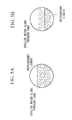
- the evaporator 13 is a flooded evaporator, into which refrigerant liquid that is reduced in pressure by an expansion valve flows, and in which heat is exchanged between the refrigerant liquid and chilled water or brine passing through a tube.
- the heat exchange causes the refrigerant liquid to evaporate, and the latent heat of evaporation thereof causes the chilled water or brine passing through the tube to be cooled.
- Equation (7) a general equation for the heat exchange in the evaporator 13 will be expressed as Equation (7).
- Equation (8) Q is the quantity of heat exchanged (kW)
- K is an average heat-transfer coefficient (kW/m 2 ⁇ K)
- A is an effective heat-transfer area (m 2 )
- ⁇ Tm is an average temperature difference (K), which is given by the following Equation (8).
- ⁇ Tm ⁇ T ⁇ 1 + ⁇ T ⁇ 2 / 2
- the average heat-transfer coefficient K and the effective heat-transfer area A are constant in the above Equation (7), if the chilled water inlet temperature Tw1 and the chilled water outlet temperature Tw2 are given, the evaporation temperature Te is uniquely determined relative to the heat exchange rate Q.
- the heat-transfer driving force that drives heat exchange is the temperature difference between the refrigerant liquid and the chilled water or brine flowing through the tube. Therefore, the larger the heat exchange rate Q is, the larger heat-transfer driving force, in other words, the larger temperature difference, that is needed.
- Fig. 3 is a diagram showing the state of heat transfer of the flooded evaporator 13.
- the evaporation temperature is constant at a predetermined value Te.
- Fig. 3 shows that chilled water at a temperature Tw1 at the inlet of the evaporator 13 (point A in Fig. 3 ) is gradually cooled by exchanging heat with cooling water in the evaporator 13 (region B in Fig. 3 ) and is cooled to a temperature Tw2 at the outlet of the evaporator 13 (point C in Fig. 3 ).
- Tw1 at the inlet of the evaporator 13
- region B in Fig. 3 region B in Fig. 3
- Tw2 the outlet of the evaporator 13
- Fig. 4 is a diagram showing the relationships between the load factor and the heat exchange loss of the evaporator 13 at various cooling-water inlet temperatures. In Fig.
- the horizontal axis indicates the load factor
- the vertical axis indicates the heat exchange loss of the evaporator 13, which is expressed as the difference between the chilled water outlet temperature and the evaporation temperature.
- Fig. 4 shows the individual relationships when the cooling-water inlet temperature was set at 13 °C, 15 °C, 20 °C, 25 °C, 29 °C, and 32 °C.
- the froth surface of the refrigerant rises due to the volume of the refrigerant that evaporates into gas, so that heat exchange is performed, with the entire tube in contact with the refrigerant liquid.
- the amount of circulating refrigerant and the amount of refrigerant that evaporates into gas are reduced, so that the level of the refrigerant liquid in the evaporator 13 falls, and thus, the effective heat-transfer area of the tube, in terms of an area in contact with the refrigerant liquid, decreases.
- the inventors conducted an experiment on the heat exchange performance of the evaporator 13 at the individual operating points, focusing on changes in effective heat-transfer area.
- the results showed that a 20% decrease in effective heat-transfer area relative to a given effective heat-transfer area causes the average temperature difference ⁇ Tm necessary for ensuring the heat exchange rate Q to increase by 1.2 times, in other words, causes the heat exchange performance to decrease.
- the characteristics that show the relationships between the load factor and the heat exchange loss of the evaporator 13 at the individual cooling-water inlet temperatures are expressed as an approximate curve, and the loss-equivalent temperature difference Tde of the evaporator 13 in Equation (6) is calculated using this characteristic.
- the mean value of heat exchange losses at the individual cooling-water inlet temperatures at the individual load factors is calculated, and an approximate expression passing through the calculated mean value is created.
- the approximate expression is given by, for example, the following Equation (9).
- Tde a ⁇ Qf + b
- Equation (9) Tde is the loss-equivalent temperature difference of the evaporator 13
- Qf is the present load factor
- a and b are constants.
- Equation (9) is expressed as a linear function having the load factor as a parameter, it may be expressed as a polynomial.
- the data acquisition section 101 acquires operating data of the variable-speed centrifugal chiller 1 as input data and outputs the acquired input data to the calculating section 103.
- the calculating section 103 calculates a target COP at the present operating point by using the foregoing arithmetic expressions stored in the storage section 102 and the operating data input from the data acquisition section 101.
- a correction term Cf corresponding to the present operating point is obtained by using the foregoing Equations (2) to (5), and the heat exchange loss Td of the heat exchangers is calculated by using Equations (6) and (9). More specifically, the present load factor is substituted for Qf in Equation (9) to calculate the loss-equivalent temperature difference Tde of the evaporator 13, and the calculated loss-equivalent temperature difference Tde of the evaporator 13 is substituted into Equation (6) to obtain the loss-equivalent temperature difference Td due to the evaporator 13 and the condenser 12. After the correction terms Cf and Td are obtained, the correction terms are substituted into Equation (1) to calculate a target COP corresponding to the present operating point.
- the calculated COP is transmitted to a monitoring unit (not shown) via a communication medium.
- the control unit 14 calculates, for example, the amount of heat output, an actual measured COP (a value obtained by dividing the amount of heat output [kW] by the amount of power consumed [kW]) at the present operating point, and so on, and these calculation results are also transmitted to the monitoring unit via a communication medium.
- the monitoring unit displays the target COP, the actual measured COP, the amount of heat output, etc. on a monitor, and these items of information are provided to the user.
- the apparatus and method for evaluating the performance of a centrifugal chiller employ the heat exchange loss of the evaporator 13 in which the load factor is considered, as compared with the heat exchange loss of the heat exchanger, which was conventionally given as a constant, the accuracy of calculation of the target COP can be improved. This allows the accuracy of evaluation of the performance of a centrifugal chiller to be improved.
- the apparatus for evaluating the performance of a centrifugal chiller may be a standalone system.
- the apparatus for evaluating the performance of a centrifugal chiller receives operating data of the centrifugal chiller from the control unit 14 via a predetermined communication medium and calculates the target COP and so on by using these items of information.
- the apparatus for evaluating the performance of a centrifugal chiller of the present invention may have this function in the monitoring unit that monitors the operation control of the centrifugal chiller.
Landscapes
- Engineering & Computer Science (AREA)
- Physics & Mathematics (AREA)
- Mechanical Engineering (AREA)
- Thermal Sciences (AREA)
- General Engineering & Computer Science (AREA)
- Air Conditioning Control Device (AREA)
- Testing Of Devices, Machine Parts, Or Other Structures Thereof (AREA)
Applications Claiming Priority (1)
| Application Number | Priority Date | Filing Date | Title |
|---|---|---|---|
| JP2011171152A JP5738116B2 (ja) | 2011-08-04 | 2011-08-04 | ターボ冷凍機の性能評価装置およびその方法 |
Publications (2)
| Publication Number | Publication Date |
|---|---|
| EP2554928A2 true EP2554928A2 (de) | 2013-02-06 |
| EP2554928A3 EP2554928A3 (de) | 2014-04-09 |
Family
ID=46982386
Family Applications (1)
| Application Number | Title | Priority Date | Filing Date |
|---|---|---|---|
| EP12178839.2A Withdrawn EP2554928A3 (de) | 2011-08-04 | 2012-08-01 | Vorrichtung und Verfahren zur Beurteilung der Leistung eines Zentrifugalkühlgerätes |
Country Status (5)
| Country | Link |
|---|---|
| US (1) | US10378794B2 (de) |
| EP (1) | EP2554928A3 (de) |
| JP (1) | JP5738116B2 (de) |
| KR (1) | KR20130016055A (de) |
| CN (1) | CN102914108B (de) |
Cited By (1)
| Publication number | Priority date | Publication date | Assignee | Title |
|---|---|---|---|---|
| CN111507009A (zh) * | 2020-04-23 | 2020-08-07 | 西安西热节能技术有限公司 | 一种基于x-比修正的回转式空气预热器换热效率计算方法 |
Families Citing this family (9)
| Publication number | Priority date | Publication date | Assignee | Title |
|---|---|---|---|---|
| CN103528835B (zh) * | 2013-05-15 | 2016-08-10 | 陈则韶 | 一种等价热力变换分析法 |
| KR20160043402A (ko) * | 2014-10-13 | 2016-04-21 | 엘지전자 주식회사 | 칠러용 컨트롤러 및 칠러의 제어방법 |
| CN107036319B (zh) * | 2016-02-04 | 2020-10-02 | 松下知识产权经营株式会社 | 制冷循环装置 |
| US10161834B1 (en) | 2016-02-05 | 2018-12-25 | William R Henry | Method to determine performance of a chiller and chiller plant |
| CN107560258A (zh) * | 2017-08-28 | 2018-01-09 | 珠海格力电器股份有限公司 | 冷水机组的性能评估方法及冷水机组 |
| US11092954B2 (en) | 2019-01-10 | 2021-08-17 | Johnson Controls Technology Company | Time varying performance indication system for connected equipment |
| US12399490B2 (en) | 2019-01-10 | 2025-08-26 | Tyco Fire & Security Gmbh | Performance monitoring and control system for connected building equipment with stability index |
| US11519620B2 (en) | 2020-09-22 | 2022-12-06 | Johnson Controls Tyco IP Holdings LLP | Stability index for connected equipment |
| CN110501377B (zh) * | 2019-09-21 | 2021-09-17 | 张家港市恒强冷却设备有限公司 | 空气换热器中换热翅片面积的校核方法 |
Citations (1)
| Publication number | Priority date | Publication date | Assignee | Title |
|---|---|---|---|---|
| JP2011106792A (ja) | 2009-11-20 | 2011-06-02 | Mitsubishi Heavy Ind Ltd | インバータターボ冷凍機の性能評価装置 |
Family Cites Families (13)
| Publication number | Priority date | Publication date | Assignee | Title |
|---|---|---|---|---|
| JP2527446B2 (ja) * | 1987-10-14 | 1996-08-21 | 株式会社神戸製鋼所 | ヒ―トポンプ |
| JPH1123113A (ja) | 1997-07-01 | 1999-01-26 | Mitsubishi Heavy Ind Ltd | 冷凍機遠隔性能診断装置 |
| KR100466433B1 (ko) | 2002-11-15 | 2005-01-14 | 삼성에스디에스 주식회사 | 터보 냉동기의 성능분석방법 및 장치 |
| ES2652023T3 (es) * | 2003-11-28 | 2018-01-31 | Mitsubishi Denki Kabushiki Kaisha | Congelador y acondicionador de aire |
| JP2006283998A (ja) * | 2005-03-31 | 2006-10-19 | Mitsubishi Electric Corp | 冷凍サイクル |
| EP2147265B8 (de) | 2007-05-22 | 2012-04-25 | Angelantoni Life Science S.r.l. | Kühlvorrichtung und -verfahren zum zirkulieren eines ihr/ihm zugeordneten kühlfluids |
| JP4930214B2 (ja) * | 2007-06-21 | 2012-05-16 | 株式会社デンソー | 冷凍サイクル装置 |
| JP5244420B2 (ja) | 2008-02-28 | 2013-07-24 | 三菱重工業株式会社 | ターボ冷凍機および熱源システムならびにこれらの制御方法 |
| JP2010127563A (ja) * | 2008-11-28 | 2010-06-10 | Sanden Corp | 冷凍システム |
| JP5404333B2 (ja) * | 2009-11-13 | 2014-01-29 | 三菱重工業株式会社 | 熱源システム |
| JP5669402B2 (ja) * | 2010-01-08 | 2015-02-12 | 三菱重工業株式会社 | ヒートポンプ及びヒートポンプの熱媒流量演算方法 |
| JP5523972B2 (ja) * | 2010-07-29 | 2014-06-18 | 三菱重工業株式会社 | ターボ冷凍機の性能評価装置 |
| JP2012052733A (ja) * | 2010-09-01 | 2012-03-15 | Mitsubishi Heavy Ind Ltd | ターボ冷凍機の性能評価装置 |
-
2011
- 2011-08-04 JP JP2011171152A patent/JP5738116B2/ja active Active
-
2012
- 2012-07-18 KR KR1020120078160A patent/KR20130016055A/ko not_active Ceased
- 2012-07-24 CN CN201210258170.0A patent/CN102914108B/zh active Active
- 2012-07-25 US US13/557,874 patent/US10378794B2/en active Active
- 2012-08-01 EP EP12178839.2A patent/EP2554928A3/de not_active Withdrawn
Patent Citations (1)
| Publication number | Priority date | Publication date | Assignee | Title |
|---|---|---|---|---|
| JP2011106792A (ja) | 2009-11-20 | 2011-06-02 | Mitsubishi Heavy Ind Ltd | インバータターボ冷凍機の性能評価装置 |
Cited By (2)
| Publication number | Priority date | Publication date | Assignee | Title |
|---|---|---|---|---|
| CN111507009A (zh) * | 2020-04-23 | 2020-08-07 | 西安西热节能技术有限公司 | 一种基于x-比修正的回转式空气预热器换热效率计算方法 |
| CN111507009B (zh) * | 2020-04-23 | 2023-04-28 | 西安西热节能技术有限公司 | 一种基于x-比修正的回转式空气预热器换热效率计算方法 |
Also Published As
| Publication number | Publication date |
|---|---|
| US20130031920A1 (en) | 2013-02-07 |
| EP2554928A3 (de) | 2014-04-09 |
| CN102914108B (zh) | 2014-12-03 |
| KR20130016055A (ko) | 2013-02-14 |
| JP2013036638A (ja) | 2013-02-21 |
| US10378794B2 (en) | 2019-08-13 |
| JP5738116B2 (ja) | 2015-06-17 |
| CN102914108A (zh) | 2013-02-06 |
Similar Documents
| Publication | Publication Date | Title |
|---|---|---|
| US10378794B2 (en) | Apparatus and method for evaluating performance of centrifugal chiller | |
| EP2330365B1 (de) | Leistungsbeurteilungsvorrichtung für ein Zentrifugalkühlgerät mit verstellbarer Geschwindigkeit | |
| EP2420759B1 (de) | System zur Beurteilung der Leistung eines Zentrifugalwasserkühlgerätes | |
| JP6324707B2 (ja) | 熱源機及びその制御方法 | |
| JP5761960B2 (ja) | 熱源装置 | |
| US9689730B2 (en) | Estimation apparatus of heat transfer medium flow rate, heat source machine, and estimation method of heat transfer medium flow rate | |
| EP2343490A2 (de) | Wärmepumpe und Verfahren zur Berechnung der Flussrate des Heizmediums in der Wärmepumpe | |
| US10139815B2 (en) | Chiller control device, chiller, and chiller diagnostic method | |
| CN101646911A (zh) | 风冷式冷却器系统运行的优化 | |
| JP5289475B2 (ja) | 冷凍サイクル装置、流量算定方法及びプログラム | |
| Velasco et al. | Energy efficiency evaluation of the use of R513A as a drop-in replacement for R134a in a water chiller with a minichannel condenser for air-conditioning applications | |
| JP6219160B2 (ja) | ターボ冷凍機の最大負荷率算出装置及びその方法並びに熱源システム及びその台数制御方法 | |
| Dabas et al. | Experimental investigation of a refrigeration system working under transient conditions | |
| JP5901191B2 (ja) | ターボ冷凍機の性能評価装置およびその方法 | |
| JP2013133957A (ja) | 流量監視装置及び流量監視システム | |
| JP2793074B2 (ja) | タービン式膨張機の運転制御方法及び装置 |
Legal Events
| Date | Code | Title | Description |
|---|---|---|---|
| PUAI | Public reference made under article 153(3) epc to a published international application that has entered the european phase |
Free format text: ORIGINAL CODE: 0009012 |
|
| AK | Designated contracting states |
Kind code of ref document: A2 Designated state(s): AL AT BE BG CH CY CZ DE DK EE ES FI FR GB GR HR HU IE IS IT LI LT LU LV MC MK MT NL NO PL PT RO RS SE SI SK SM TR |
|
| AX | Request for extension of the european patent |
Extension state: BA ME |
|
| PUAL | Search report despatched |
Free format text: ORIGINAL CODE: 0009013 |
|
| AK | Designated contracting states |
Kind code of ref document: A3 Designated state(s): AL AT BE BG CH CY CZ DE DK EE ES FI FR GB GR HR HU IE IS IT LI LT LU LV MC MK MT NL NO PL PT RO RS SE SI SK SM TR |
|
| AX | Request for extension of the european patent |
Extension state: BA ME |
|
| RIC1 | Information provided on ipc code assigned before grant |
Ipc: F25B 49/02 20060101ALI20140305BHEP Ipc: F25B 1/053 20060101AFI20140305BHEP Ipc: F25B 40/02 20060101ALN20140305BHEP Ipc: F25B 25/00 20060101ALN20140305BHEP Ipc: F25B 1/10 20060101ALN20140305BHEP |
|
| 17P | Request for examination filed |
Effective date: 20141007 |
|
| RBV | Designated contracting states (corrected) |
Designated state(s): AL AT BE BG CH CY CZ DE DK EE ES FI FR GB GR HR HU IE IS IT LI LT LU LV MC MK MT NL NO PL PT RO RS SE SI SK SM TR |
|
| RAP1 | Party data changed (applicant data changed or rights of an application transferred) |
Owner name: MITSUBISHI HEAVY INDUSTRIES THERMAL SYSTEMS, LTD. |
|
| STAA | Information on the status of an ep patent application or granted ep patent |
Free format text: STATUS: EXAMINATION IS IN PROGRESS |
|
| 17Q | First examination report despatched |
Effective date: 20190326 |
|
| GRAP | Despatch of communication of intention to grant a patent |
Free format text: ORIGINAL CODE: EPIDOSNIGR1 |
|
| STAA | Information on the status of an ep patent application or granted ep patent |
Free format text: STATUS: GRANT OF PATENT IS INTENDED |
|
| RIC1 | Information provided on ipc code assigned before grant |
Ipc: F25B 1/053 20060101AFI20200116BHEP Ipc: F25B 1/10 20060101ALN20200116BHEP Ipc: F25B 49/02 20060101ALI20200116BHEP Ipc: F25B 25/00 20060101ALN20200116BHEP Ipc: F25B 40/02 20060101ALN20200116BHEP |
|
| INTG | Intention to grant announced |
Effective date: 20200131 |
|
| STAA | Information on the status of an ep patent application or granted ep patent |
Free format text: STATUS: THE APPLICATION IS DEEMED TO BE WITHDRAWN |
|
| 18D | Application deemed to be withdrawn |
Effective date: 20200611 |