EP2551995B1 - Fahrzeug mit antriebsmotor - Google Patents
Fahrzeug mit antriebsmotor Download PDFInfo
- Publication number
- EP2551995B1 EP2551995B1 EP10848429.6A EP10848429A EP2551995B1 EP 2551995 B1 EP2551995 B1 EP 2551995B1 EP 10848429 A EP10848429 A EP 10848429A EP 2551995 B1 EP2551995 B1 EP 2551995B1
- Authority
- EP
- European Patent Office
- Prior art keywords
- side member
- rotative
- fixed
- rotor
- axle
- Prior art date
- Legal status (The legal status is an assumption and is not a legal conclusion. Google has not performed a legal analysis and makes no representation as to the accuracy of the status listed.)
- Not-in-force
Links
- 235000012489 doughnuts Nutrition 0.000 claims description 5
- 230000010354 integration Effects 0.000 description 6
- 230000007246 mechanism Effects 0.000 description 5
- XLYOFNOQVPJJNP-UHFFFAOYSA-N water Substances O XLYOFNOQVPJJNP-UHFFFAOYSA-N 0.000 description 5
- 238000003780 insertion Methods 0.000 description 4
- 230000037431 insertion Effects 0.000 description 4
- 230000004048 modification Effects 0.000 description 3
- 238000012986 modification Methods 0.000 description 3
- 230000008901 benefit Effects 0.000 description 2
- 230000000694 effects Effects 0.000 description 2
- 238000005549 size reduction Methods 0.000 description 2
- 239000003086 colorant Substances 0.000 description 1
- 238000001514 detection method Methods 0.000 description 1
- 239000000428 dust Substances 0.000 description 1
- 238000010348 incorporation Methods 0.000 description 1
- 238000004519 manufacturing process Methods 0.000 description 1
- 238000003825 pressing Methods 0.000 description 1
Images


Classifications
-
- H—ELECTRICITY
- H02—GENERATION; CONVERSION OR DISTRIBUTION OF ELECTRIC POWER
- H02K—DYNAMO-ELECTRIC MACHINES
- H02K7/00—Arrangements for handling mechanical energy structurally associated with dynamo-electric machines, e.g. structural association with mechanical driving motors or auxiliary dynamo-electric machines
- H02K7/10—Structural association with clutches, brakes, gears, pulleys or mechanical starters
- H02K7/116—Structural association with clutches, brakes, gears, pulleys or mechanical starters with gears
-
- H—ELECTRICITY
- H02—GENERATION; CONVERSION OR DISTRIBUTION OF ELECTRIC POWER
- H02K—DYNAMO-ELECTRIC MACHINES
- H02K15/00—Processes or apparatus specially adapted for manufacturing, assembling, maintaining or repairing of dynamo-electric machines
- H02K15/16—Centring rotors within the stators
-
- B—PERFORMING OPERATIONS; TRANSPORTING
- B60—VEHICLES IN GENERAL
- B60K—ARRANGEMENT OR MOUNTING OF PROPULSION UNITS OR OF TRANSMISSIONS IN VEHICLES; ARRANGEMENT OR MOUNTING OF PLURAL DIVERSE PRIME-MOVERS IN VEHICLES; AUXILIARY DRIVES FOR VEHICLES; INSTRUMENTATION OR DASHBOARDS FOR VEHICLES; ARRANGEMENTS IN CONNECTION WITH COOLING, AIR INTAKE, GAS EXHAUST OR FUEL SUPPLY OF PROPULSION UNITS IN VEHICLES
- B60K7/00—Disposition of motor in, or adjacent to, traction wheel
-
- B—PERFORMING OPERATIONS; TRANSPORTING
- B62—LAND VEHICLES FOR TRAVELLING OTHERWISE THAN ON RAILS
- B62K—CYCLES; CYCLE FRAMES; CYCLE STEERING DEVICES; RIDER-OPERATED TERMINAL CONTROLS SPECIALLY ADAPTED FOR CYCLES; CYCLE AXLE SUSPENSIONS; CYCLE SIDE-CARS, FORECARS, OR THE LIKE
- B62K11/00—Motorcycles, engine-assisted cycles or motor scooters with one or two wheels
- B62K11/02—Frames
- B62K11/04—Frames characterised by the engine being between front and rear wheels
-
- H—ELECTRICITY
- H02—GENERATION; CONVERSION OR DISTRIBUTION OF ELECTRIC POWER
- H02K—DYNAMO-ELECTRIC MACHINES
- H02K5/00—Casings; Enclosures; Supports
- H02K5/04—Casings or enclosures characterised by the shape, form or construction thereof
- H02K5/16—Means for supporting bearings, e.g. insulating supports or means for fitting bearings in the bearing-shields
- H02K5/173—Means for supporting bearings, e.g. insulating supports or means for fitting bearings in the bearing-shields using bearings with rolling contact, e.g. ball bearings
- H02K5/1737—Means for supporting bearings, e.g. insulating supports or means for fitting bearings in the bearing-shields using bearings with rolling contact, e.g. ball bearings radially supporting the rotor around a fixed spindle; radially supporting the rotor directly
-
- H—ELECTRICITY
- H02—GENERATION; CONVERSION OR DISTRIBUTION OF ELECTRIC POWER
- H02K—DYNAMO-ELECTRIC MACHINES
- H02K7/00—Arrangements for handling mechanical energy structurally associated with dynamo-electric machines, e.g. structural association with mechanical driving motors or auxiliary dynamo-electric machines
- H02K7/14—Structural association with mechanical loads, e.g. with hand-held machine tools or fans
-
- B—PERFORMING OPERATIONS; TRANSPORTING
- B60—VEHICLES IN GENERAL
- B60L—PROPULSION OF ELECTRICALLY-PROPELLED VEHICLES; SUPPLYING ELECTRIC POWER FOR AUXILIARY EQUIPMENT OF ELECTRICALLY-PROPELLED VEHICLES; ELECTRODYNAMIC BRAKE SYSTEMS FOR VEHICLES IN GENERAL; MAGNETIC SUSPENSION OR LEVITATION FOR VEHICLES; MONITORING OPERATING VARIABLES OF ELECTRICALLY-PROPELLED VEHICLES; ELECTRIC SAFETY DEVICES FOR ELECTRICALLY-PROPELLED VEHICLES
- B60L2200/00—Type of vehicles
- B60L2200/12—Bikes
-
- B—PERFORMING OPERATIONS; TRANSPORTING
- B60—VEHICLES IN GENERAL
- B60L—PROPULSION OF ELECTRICALLY-PROPELLED VEHICLES; SUPPLYING ELECTRIC POWER FOR AUXILIARY EQUIPMENT OF ELECTRICALLY-PROPELLED VEHICLES; ELECTRODYNAMIC BRAKE SYSTEMS FOR VEHICLES IN GENERAL; MAGNETIC SUSPENSION OR LEVITATION FOR VEHICLES; MONITORING OPERATING VARIABLES OF ELECTRICALLY-PROPELLED VEHICLES; ELECTRIC SAFETY DEVICES FOR ELECTRICALLY-PROPELLED VEHICLES
- B60L2220/00—Electrical machine types; Structures or applications thereof
- B60L2220/40—Electrical machine applications
- B60L2220/44—Wheel Hub motors, i.e. integrated in the wheel hub
-
- B—PERFORMING OPERATIONS; TRANSPORTING
- B60—VEHICLES IN GENERAL
- B60L—PROPULSION OF ELECTRICALLY-PROPELLED VEHICLES; SUPPLYING ELECTRIC POWER FOR AUXILIARY EQUIPMENT OF ELECTRICALLY-PROPELLED VEHICLES; ELECTRODYNAMIC BRAKE SYSTEMS FOR VEHICLES IN GENERAL; MAGNETIC SUSPENSION OR LEVITATION FOR VEHICLES; MONITORING OPERATING VARIABLES OF ELECTRICALLY-PROPELLED VEHICLES; ELECTRIC SAFETY DEVICES FOR ELECTRICALLY-PROPELLED VEHICLES
- B60L2220/00—Electrical machine types; Structures or applications thereof
- B60L2220/40—Electrical machine applications
- B60L2220/46—Wheel motors, i.e. motor connected to only one wheel
-
- H—ELECTRICITY
- H02—GENERATION; CONVERSION OR DISTRIBUTION OF ELECTRIC POWER
- H02K—DYNAMO-ELECTRIC MACHINES
- H02K21/00—Synchronous motors having permanent magnets; Synchronous generators having permanent magnets
- H02K21/12—Synchronous motors having permanent magnets; Synchronous generators having permanent magnets with stationary armatures and rotating magnets
- H02K21/22—Synchronous motors having permanent magnets; Synchronous generators having permanent magnets with stationary armatures and rotating magnets with magnets rotating around the armatures, e.g. flywheel magnetos
-
- H—ELECTRICITY
- H02—GENERATION; CONVERSION OR DISTRIBUTION OF ELECTRIC POWER
- H02K—DYNAMO-ELECTRIC MACHINES
- H02K2201/00—Specific aspects not provided for in the other groups of this subclass relating to the magnetic circuits
- H02K2201/03—Machines characterised by aspects of the air-gap between rotor and stator
-
- H—ELECTRICITY
- H02—GENERATION; CONVERSION OR DISTRIBUTION OF ELECTRIC POWER
- H02K—DYNAMO-ELECTRIC MACHINES
- H02K5/00—Casings; Enclosures; Supports
- H02K5/04—Casings or enclosures characterised by the shape, form or construction thereof
- H02K5/10—Casings or enclosures characterised by the shape, form or construction thereof with arrangements for protection from ingress, e.g. water or fingers
-
- Y—GENERAL TAGGING OF NEW TECHNOLOGICAL DEVELOPMENTS; GENERAL TAGGING OF CROSS-SECTIONAL TECHNOLOGIES SPANNING OVER SEVERAL SECTIONS OF THE IPC; TECHNICAL SUBJECTS COVERED BY FORMER USPC CROSS-REFERENCE ART COLLECTIONS [XRACs] AND DIGESTS
- Y02—TECHNOLOGIES OR APPLICATIONS FOR MITIGATION OR ADAPTATION AGAINST CLIMATE CHANGE
- Y02T—CLIMATE CHANGE MITIGATION TECHNOLOGIES RELATED TO TRANSPORTATION
- Y02T10/00—Road transport of goods or passengers
- Y02T10/60—Other road transportation technologies with climate change mitigation effect
- Y02T10/64—Electric machine technologies in electromobility
Definitions
- This invention relates to a vehicle equipped with a driving motor. More particularly, it relates to a vehicle with a driving motor incorporated in a wheel.
- the vehicle equipped with the driving motor as described is such that a wheel (40) provided therein with a motor (20) having a stator (21) and a rotor (22) and equipped with a fixed-side member (11) supporting the stator (21) and a rotative-side member (42) receiving rotation transmitted from the rotor (22) is supported between a pair of front forks (5) and (5) with a wheel axle (49).
- the fixed-side member (11) supporting the stator (21) is supported with the wheel axle (49)
- the rotor (22) is supported with the wheel axle (49) through an axle (24)
- the rotative-side member (42) receiving rotation transmitted from the rotor (22) is supported with the wheel axle (49) through a bearing (47)
- the axle (24) has no engaging part for engagement with the fixed-side member (11) .
- the above prior art involves the occurrence of mutual misalignment of insertion holes in the fixed-side member (11) and the axle (24) when inserting the wheel axle (49) into the fixed-side member (11) and the axle (24).
- Such situation when occurred, meets with the difficulty of inserting the wheel axle (49), and as a result, incorporation of the wheel in between the front forks (5) and (5) becomes hard to be effected.
- An object of the present invention for solving the above problems is to provide a vehicle equipped with a driving motor, in which it is less likely that water or the like can enter.
- a vehicle equipped with a driving motor of the present invention more specifically, a vehicle equipped with a driving motor, in which a wheel provided therein with a motor having a stator and a rotor and equipped with a fixed-side member supporting the above stator and a rotative-side member receiving rotation transmitted from the above rotor is supported between a pair of arms with a wheel axle, wherein on an axle are rotatively supported the above rotor and the rotative-side member, and there is provided at the above axle an engaging part for engagement with the above fixed-side member to position the center of rotation of the rotative-side member with respect to the above fixed-side member, wherein the above rotative-side member and the fixed-side member are integrated into a unit by engagement of the engaging part of the axle with the above fixed-side member, the unit of which is supported between the above pair of arms with the above wheel axle.
- the above fixed-side member has a disk fixed to one of the above pair of arms and a cylindrical part so extending from the circumference of the disk to the rotative-side member side as to cover the above stator and the rotor, wherein an annular end of the cylindrical part and the above rotative-side member are brought into an overlap on the center line of the vehicle, an overlap portion of which is adapted to form a labyrinth seal.
- the above rotor is supported with the above rotative-side member.
- the above rotative-side member has a sleeve rotatively supported on the above axle and a flange provided on the outer circumference of the sleeve, wherein to the flange is fastened the above rotor, and the above sleeve is formed more projecting with respect to an axial direction thereof than a part where the above rotor is fastened, a projection of which is supported on the above axle through a bearing.
- the above rotor is of the form of an outer rotor located on the outer circumference of the above stator, and the above stator is of a doughnut form having a space in the center of the stator, wherein in the above space is disposed the projection of the sleeve included in the above rotative-side member.
- the engaging part of the above axle is more projecting with respect to the axial direction toward the above fixed-side member than the projection of the sleeve included in the rotative-side member, wherein engagement of the above engaging part with the fixed-side member is provided before the above rotor and the stator are overlapped when bringing axially closer to each other the rotative-side member supporting the above rotor and the f ixed-side member supporting the above stator.
- the above labyrinth seal is formed in such a manner that there is provided at an annular end of the above cylindrical part a step having a diameter increasing toward the rotative-side member side, while there are provided on the above rotative-side member an axially-extending irregularity and a radially-extending irregularity.
- the engaging part for engagement with the fixed-side member to position the center of rotation of the rotative-side member with respect to the fixed-side member, so that integration of the fixed-side member and the rotative-side member into the unit by engagement of the engaging part with the fixed-side member is adapted to allow the axle to be positioned with respect to the fixed-side member, resulting in that the centers of the holes in the axle and the fixed-side member for insertion of the wheel axle will be in alignment.
- the above fixed-side member is of the form having the disk fixed to one of the above pair of arms and the cylindrical part so extending from the circumference of the disk to the rotative-side member side as to cover the rotor and the stator, wherein the annular end of the cylindrical part and the above rotative-side member are brought into the overlap on the center line of the vehicle, so that it becomes possible to form the labyrinth seal in such a position that water or the like is hard to enter.
- the above rotor is supported with the above rotative-side member, so that it is possible to position also the center of rotation of the rotor with respect to the stator supported on the fixed-side member at the same time as positioning of the center of rotation of the rotative-side member with respect to the fixed-side member.
- the above rotative-side member is of the form having the sleeve rotatively supported on the above axle and the flange provided on the outer circumference of the sleeve, wherein to the flange is fastened the above rotor, and the above sleeve is formed more projecting with respect to the axial direction thereof than the part where the above rotor is fastened, the projection of which is supported on the above axle through the bearing, so that it is possible to support in a stable state the rotative-side member holding a tire and the above rotor.
- the above rotor is of the form of the outer rotor located on the outer circumference of the above stator, and the above stator is of the doughnut form having the space in the center of the stator, wherein in the above space is disposed the projectionof the sleeve included in the above rotative-side member, so that it is possible to provide a wheel size reduction by effectively taking advantage of the space in the center of the stator.
- the engaging part of the above axle is formed more projecting with respect to the axial direction thereof toward the above fixed-side member than the projection of the sleeve included in the above rotative-side member, wherein engagement of the above engaging part with the fixed-side member is provided before the above rotor and the stator are overlapped when bringing axially closer to each other the rotative-side member supporting the above rotor and the fixed-side member supporting the above stator, so that it is possible to bring the engaging part into engagement with the fixed-side member before magnetic attraction produced between the rotor and the stator becomes increased, and consequently, integration into the above unit will be effected easily.
- the above labyrinth seal is formed in such a manner that there is provided at the annular end of the above cylindrical part the step having the diameter increasing toward the above rotative-side member side, while there are provided on the rotative-side member the axially-extending irregularity and the radially-extending irregularity, so that it is possible to provide an increased seal property.
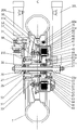
- a vehicle 10 equipped with a driving motor is of the form of a motorcycle and has a frame 11 forming a vehicle body.
- a head pipe 12 forming the front end of the frame 11 is attached a pair of front forks 20 as a pair of arms so that they may be free to steer.
- a bar handle 14 To the tops of the front forks 20 is attached a bar handle 14.
- a front wheel 30 To the bottoms of the front forks 20 is attached a front wheel 30 as a wheel.
- To the inside of the frame 11 is fixed an engine 15.
- To the engine 15 are connected an intake system 15i and an exhaust system 15o.
- To the rear of the frame 11 is attached a pair of left and right swing arms 16 with a pivot shaft 17 so that they may be free to swing upward and downward.
- a rear wheel 17 To the rear ends of the swing arms 16 is attached a rear wheel 17.
- the rear wheel 17 may be driven with the engine 15 through non-illustrated driving force transmitting means such as chain and drive shaft.
- Reference numeral 18 indicates a rear cushion unit, an upper end of which being connected to the top of the rear of the frame 11, and a lower end of which being connected to the bottom of the swing arm 16 and to the bottom of the rear of the vehicle body frame 11.
- the motorcycle of this type is such that in addition to the rear wheel 17, the front wheel 30 is also formed as a drive wheel. There is further provided a braking device for the front wheel 30.
- the front wheel 30 is driven with a motor incorporated in the front wheel 30.
- reference numeral 40 indicates the motor.
- the motor 40 has a stator 41 and a rotor 42 and forms a drive source of the front wheel 30.
- On a wheel axle 21 is rotatively supported the front wheel 30 between the pair of left and right arms, or the left and right front forks 20L and 20R for this embodiment.
- the motor 40 is disposed inside a hub of the front wheel 30.
- the front wheel 30 is provided with a braking mechanism 50.
- the braking mechanism 50 is disposed on one side (on the left in FIG. 2 ) away from a vehicle body center C, as seen from the front of the vehicle body as shown in FIG. 2 .
- the motor 40 is disposed on the other side (on the right in FIG. 2 ) away from the vehicle body center C.
- the braking mechanism 50 more specifically, a braking part 52 generating a braking force and a braked unit 51 receiving the thus generated braking force, as described later, are disposed on one side away from the vehicle body center C in between the front forks 20L and 20R, and the motor 40 is disposed on the other side away from the vehicle body center C in between the front forks 20L and 20R, as seen from the front of the vehicle body.
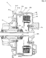
- the front wheel 30 has a fixed-side member 60 supporting the stator 41 of the motor 40 and a wheel hub 31 as a rotative-side member receiving rotation transmitted from the rotor 42.
- the front wheel 30 is driven by means of driving of the motor 40 through the wheel hub 31.
- the front wheel 30 is fixed to the wheel hub 31 with a stud bolt 33.
- axle 22 is of the form of a cylindrical axle collar 22 into which the wheel axle 21 is inserted.
- axle 22 will be hereinafter also referred to as the axle collar 22.
- an engaging part 22p for engagement with the fixed-side member 60 to position the center of rotation of the rotative-side member 31 with respect to the fixed-side member 60.
- the engaging part 22p may be of the form of a small-diameter part formed through a step 22d (see FIG. 3 ) .
- a fixed-side member 60-side engaging part may be of the form of a hole 60h into which the above small-diameter part 22p is inserted.
- the rotative-side member 31 and the fixed-side member 60 may be integrated into a unit by engagement of the engaging part 22p of the axle collar 22 with the fixed-side member 60 (or by fitting the small-diameter part 22p into the hole 60h of the fixed-side member 60 for this embodiment).
- a unit U of which will be supported between the pair of arms 20L and 20R with the wheel axle 21 inserted into the axle collar 22, as shown in FIG. 2 .
- the rotative-side member 31 has a sleeve 31b rotatively supported on the axle collar 22 and a flange 31f provided on the outer circumference of the sleeve 31b. To the flange 31f is fastened the rotor 42 with a socket bolt 42b. Thus, the rotor 42 is supported with the rotative-side member 31.
- the sleeve 31b of the rotative-side member 31 is more projecting with respect to the axial direction thereof (leftward and rightward in FIGS. 2 and 3 ) toward the fixed-side member 60 than a part where the rotor 42 is fastened, a projection 31c of which is supported on the axle 22 through a bearing 25. It is noted that the other end side of the sleeve 31b is rotatively supported on the wheel axle 21 through a bearing 26.
- the rotor 42 is of the form of an outer rotor located on the outer circumference of the stator 41.
- the rotor 42 is comprised of a member having an approximately channel-shaped section as a whole and has on its inside surface facing the stator 41 a magnet 46.
- To the flange 31f of the rotative-side member 31 is fixed a center portion of the rotor 42 with the above socket bolt 42b.
- the stator 41 is of a doughnut form having a space 41s (see FIG. 3 ) in the center of the stator, wherein in the space 41s is disposed the projection 31c of the sleeve 31b included in the rotative-side member 31.
- FIG. 4 is a view showing the state in which the engaging part 22p of the axle collar 22 has started making engagement with the engaging part 60h of the fixed-side member 60 in the course of integration into the unit U.
- the engaging part 22p of the axle collar 22 is more proj ecting with respect to the axial direction thereof toward the fixed-side member 60 than the projection 31c of the sleeve 31b included in the rotation-side member 31.
- Engagement of the engaging part 22p with the engaging part 60h of the fixed-side member 60 is provided before the rotor 42 and the stator 41 are overlapped (more exactly, before attraction force caused by magnetic attraction produced between the rotor 42 and the stator 41 becomes so increased that operation of engagement of the engaging part 22p of the axle collar 22 with the engaging part 60h of the fixed-side member 60 is hard to be effected) when bringing axially closer to each other the rotative-side member 31 supporting the rotor 42 and the fixed-side member 60 supporting the stator 41 for integration into the unit, as shown in FIG. 4 .
- the fixed-side member 60 has a disk 61 fixed to one of the pair of arms 20L and 20R, i.e., the arm 20L and a cylindrical part 60b so extending from the circumference of the disk 61 to the rotative-side member 31-side as to cover the stator 41 and the rotor 42.
- An annular end 60e of the cylindrical part 60b and an outer circumference 31e of the flange 31f included in the rotative-side member 31 are brought into an overlap on a center line C of the vehicle as shown in FIG. 2 , an overlap portion of which is adapted to form a labyrinth seal 35.
- the labyrinth seal 35 is composed of the above annular end 60e having a diameter increasing toward the rotative-side member 31-side through a step 60d in the cylindrical part 60b of the fixed-side member 60 and an axially-extending ring-shaped irregularity 31d1 and a radially-extending irregularity 31d2, both irregularities being provided on the outer circumference 31e of the flange 31f included in the rotative-side member 31.
- the above wheel axle 21 is of the form of an axle bolt and is fixed to the ends of the front forks 20L and 20R with an axle nut 21n.
- the fixed-side member 60 On the wheel axle 21 are mounted, right-to-left in FIG. 2 , the fixed-side member 60, the axle color 22, a side collar 23, the ball bearings 25 and 26 and a side color 29, all of which being fastened together and secured in position between the front forks 20L and 20R with the axle nut 21n.
- FIG. 2 there are integrally provided a convex part 61p on the outside of the fixed-side member 60, wherein engagement of the convex part 61p with the front fork 20L is adapted to surely prevent the fixed-side member 60 from being moved about the wheel axle 21 and the axle collar 22.
- reference numeral 43 indicates a power line of the motor 40.
- the power line 43 drawn out through the hole 63 is supported on a cover 64 through a grommet 66 and is further connected to a non-illustrated motor battery serving as a power supply.
- the battery is mounted on the vehicle body frame 11.
- the cover 64 is secured to the outside of the fixed-side member 60 with a bolt 65 (see FIG. 1 ) in order to block up the hole 63.
- a magnetic sensor 44 located inside the stator 41, and the magnetic sensor 44 is adapted to provide detection of rotation of the rotor 42 by means of sensing of a magnet 45 provided on the rotor 42.
- a signal line (not shown) of the magnetic sensor is drawn out in the same manner as the power line 43 and is connected to a control device included in this motorcycle 10.
- FIG. 2 there is shown the downwardly drawn-out power line 43, which is that given by means of development of a section in FIG. 1 , and, as a matter of fact, the power line 43 is of the form of an upwardly drawn-out power line as shown in FIG. 1 .
- wiring (the power line 43 and the signal line) for the motor 40 maybe inserted through the fixed-side member 60.
- the wiring is inserted, at the rear of the front fork 20L, through the hole 63 of the fixed-side member 60, followed by being arranged along the front fork 20L, as shown in FIG. 1 .
- the power line 43 and the signal line are both connected to the control device (not shown) mounted in its proper position of the vehicle body frame 11.
- the braking mechanism 50 has the braked part 51 fixed to the wheel hub 31 and rotated together with the wheel hub 31 (i.e., the front wheel 30) and the braking unit 52 braking rotation of the braked unit 51.
- the braked unit 51 is of the form of a brake disk fixed to the outside of the wheel hub 31 with the bolt 53
- the braking unit 52 is of the form of a caliper fixed to the front fork 20R.
- the braking unit 52 and the braked unit 51 are both located between the front forks 20L and 20R.
- the caliper 52 used may be of a well-known structure and thus has a pair of brake pads 54 applying pressure to pinch the brake disk 51 from the opposite sides thereof for braking.
- FIG. 5 is a sectional view showing one modification of the unit U.
- the illustrated unit U is characterized in that the axle 22 (the axle collar) 22 has an end 22b formed as an extended part 22b in the form of a small-diameter cylindrical part, wherein engagement of the extended part 22b with the ball bearing 26 and the side collar 29 is adapted to allow the axle collar 22 to be positioned with respect to the ball bearing 26 and the side collar 29.
- the vehicle equipped with the driving motor according to the present invention provides facilitated operation of incorporating in between the pair of arms the wheel equipped with the unit including the driving motor, so that such facilitated incorporating operation is thus applicable for use in manufacturing the vehicle with the driving motor incorporated in the wheel.
Landscapes
- Engineering & Computer Science (AREA)
- Power Engineering (AREA)
- Mechanical Engineering (AREA)
- Manufacturing & Machinery (AREA)
- Chemical & Material Sciences (AREA)
- Combustion & Propulsion (AREA)
- Transportation (AREA)
- Arrangement Or Mounting Of Propulsion Units For Vehicles (AREA)
- Connection Of Motors, Electrical Generators, Mechanical Devices, And The Like (AREA)
- Permanent Magnet Type Synchronous Machine (AREA)
Claims (6)
- Fahrzeug, ausgerüstet mit einem Antriebsmotor (40), bei dem ein Rad (30), in dem ein Motor, der einen Stator (41) und einen Rotor (42) hat, vorgesehen ist, und das mit einem Festseitenelement (60), das den Stator (41) trägt, und einen rotationsseitigen Element (31), das eine Rotation aufnimmt, die von dem Rotor (42) übertragen wird, mit einer Radachse zwischen einem Paar von Armen (20) (21) getragen wird, wobei
auf einer Achse (22) der Rotor (42) und das rotationsseitige Element (31) rotationsfähig getragen wird und dort an der Achse (22) ein Eingreifteil (22p) zum Eingreifen in das Festseitenelement (60) vorgesehen ist, um das Rotationszentrum des rotationsseitigen Elements (31) in Bezug auf das Festseitenelement (60) zu positionieren, wobei das rotationsseitige Element (31) und das Festseitenelement durch Eingreifen des Eingreifteils (22P) der Achse (22) in das Festseitenelement (60) in einer Einheit integriert sind, wobei die Einheit daraus zwischen dem Paar von Armen (20) durch die Radachse (21) getragen wird,
dadurch gekennzeichnet, dass
das Festseitenelement (60) eine Scheibe (61) hat, die an einem oder dem Paar von Armen (20) fixiert ist, und einen zylindrischen Teil (60b), der sich so von dem Umfang der Scheibe (41) zu dem rotationsseitigen Element (31) erstreckt, dass es den Stator (41) und den Rotor (42) abdeckt, wobei ein ringförmiges Ende (60e) des zylindrischen Teils (60b) und das rotationsseitige Element (31) auf der Mittellinie (c) des Fahrzeugs (10) in Überlappung gebracht werden, dessen überlappender Bereich eingerichtet ist, um eine Labyrinthdichtung (35) zu bilden. - Fahrzeug, ausgerüstet mit dem Antriebsmotor (40) gemäß Anspruch 1, wobei der Rotor (42) durch das rotationsseitige Element (31) getragen wird.
- Fahrzeug, ausgerüstet mit dem Antriebsmotor (40) gemäß Anspruch 2, wobei das rotationsseitige Element (31) eine Hülse (31b) die rotierbar an der Achse (22) gehalten wird, und einen Flansch (31f) hat, der an dem äußeren Umfang der Hülse (31b) vorgesehen ist, wobei der Flansch (31f) an dem Rotor (42) befestigt ist und die Hülse (31b) so geformt ist, dass sie in Bezug auf ihre axiale Richtung mehr vorsteht, als ein Teil, an dem der Rotor (42) befestigt ist, dessen Vorsprung an einer Achse (22) durch ein Lager (25) gehalten wird.
- Fahrzeug, ausgerüstet mit dem Antriebsmotor (40) gemäß Anspruch 3, wobei der Rotor (42) von einer Form eines äußeren Rotors (42) ist, der an einem äußeren Umfang des Stators (41) angeordnet ist, und der Stator (41) eine Doughnutform hat, die einen Raum (41 s) in der Mitte des Stators (41) hat, wobei in dem Raum (41) der Vorsprung (31c) der Hülse (31b), die in dem rotationsseitigem Element (31) umfasst ist, angeordnet ist.
- Fahrzeug, ausgerüstet mit dem Antriebsmotor (40) gemäß Anspruch 3 oder 4, wobei das Eingreifteil (22p) der Achse (22) in Bezug auf ihre axiale Richtung mehr in Richtung des Festseitenelements (60) hervorsteht als der Vorsprung (31c) der Hülse (31), die von dem rotationsseitigen Element (31) umfasst ist, wobei ein Eingreifen des Eingreifteils (22) in das Festseitenelement (60) erfolgt, bevor der Rotor (42) und der Stator (41) überlappen, wenn das rotationsseitige Element (31), das den Rotor (42) hält, und das Festseitenelement (60), das den Stator (41) trägt axial näher zueinander gebracht werden.
- Fahrzeug, ausgerüstet mit dem Antriebsmotor (40) gemäß irgendeinem der Ansprüche 1 bis 5, wobei die Labyrinthdichtung (35) in einer solchen Weise gebildet ist, dass an dem ringförmigen Ende (60e) des zylindrischen Teils (60b) eine Stufe (60d) vorgesehen ist, die einen Durchmesser hat, der auf das rotationsseitige Element (31) zu größer wird, während an dem rotationsseitigen Element (31) eine sich axial erstreckende Irregularität (31d1) vorgesehen ist und eine sich radial erstreckende Irregularität (31d2).
Applications Claiming Priority (1)
| Application Number | Priority Date | Filing Date | Title |
|---|---|---|---|
| PCT/JP2010/055439 WO2011118036A1 (ja) | 2010-03-26 | 2010-03-26 | 駆動用モータを備える車両 |
Publications (3)
| Publication Number | Publication Date |
|---|---|
| EP2551995A1 EP2551995A1 (de) | 2013-01-30 |
| EP2551995A4 EP2551995A4 (de) | 2015-07-22 |
| EP2551995B1 true EP2551995B1 (de) | 2017-03-01 |
Family
ID=44672625
Family Applications (1)
| Application Number | Title | Priority Date | Filing Date |
|---|---|---|---|
| EP10848429.6A Not-in-force EP2551995B1 (de) | 2010-03-26 | 2010-03-26 | Fahrzeug mit antriebsmotor |
Country Status (10)
| Country | Link |
|---|---|
| US (1) | US8813886B2 (de) |
| EP (1) | EP2551995B1 (de) |
| JP (1) | JP5508519B2 (de) |
| KR (1) | KR101435306B1 (de) |
| CN (1) | CN102804555B (de) |
| BR (1) | BR112012024208A2 (de) |
| CA (1) | CA2792531C (de) |
| ES (1) | ES2619584T3 (de) |
| TW (1) | TWI447043B (de) |
| WO (1) | WO2011118036A1 (de) |
Families Citing this family (11)
| Publication number | Priority date | Publication date | Assignee | Title |
|---|---|---|---|---|
| JP5149938B2 (ja) * | 2010-06-11 | 2013-02-20 | 株式会社シマノ | モータ内蔵自転車用ハブ |
| US10308352B2 (en) * | 2014-12-12 | 2019-06-04 | Borealis Technical Limited | Monitoring system for aircraft drive wheel system |
| US10532649B2 (en) * | 2015-03-23 | 2020-01-14 | Freni Brembo, S.P.A. | Electric motor assembly for a motor vehicle and brake |
| US10464633B2 (en) * | 2015-06-19 | 2019-11-05 | Robert Bosch Gmbh | Electric vehicle and driving system for electric vehicle |
| JP6584198B2 (ja) * | 2015-07-31 | 2019-10-02 | Ntn株式会社 | 発電機付き車輪用軸受装置 |
| US11143309B2 (en) * | 2018-10-09 | 2021-10-12 | Hamilton Sundstrand Corporation | Disconnect bearing and input seal for a variable frequency starter generator |
| MX2021006995A (es) * | 2018-12-13 | 2021-08-11 | Bajaj Auto Ltd | Un vehiculo electrico. |
| WO2023079844A1 (ja) * | 2021-11-05 | 2023-05-11 | パナソニックIpマネジメント株式会社 | モータ、ブロア、及び、車両 |
| JP7338671B2 (ja) * | 2021-11-18 | 2023-09-05 | いすゞ自動車株式会社 | インホイールモータ |
| JP7342092B2 (ja) * | 2021-11-18 | 2023-09-11 | いすゞ自動車株式会社 | インホイールモータ |
| JP7435581B2 (ja) * | 2021-11-18 | 2024-02-21 | いすゞ自動車株式会社 | インホイールモータ |
Family Cites Families (24)
| Publication number | Priority date | Publication date | Assignee | Title |
|---|---|---|---|---|
| DE4218888C2 (de) * | 1992-06-09 | 1995-06-08 | Barth Hubert Dipl Ing Fh | Elektrische Maschine |
| JP3363682B2 (ja) * | 1995-12-19 | 2003-01-08 | 株式会社ミツバ | 磁石発電機 |
| AT405390B (de) * | 1997-03-19 | 1999-07-26 | Abb Daimler Benz Transp | Elektromotorischer radnabenantrieb für ein fahrzeugrad |
| US6199651B1 (en) * | 1997-12-11 | 2001-03-13 | Vectrix Corporation | Vehicle drive wheel assembly |
| GB2369503A (en) * | 2000-11-28 | 2002-05-29 | Evt Technology Co Ltd | Direct-drive wheel motor |
| TWI268320B (en) * | 2001-12-04 | 2006-12-11 | Yamaha Motor Co Ltd | Continuously variable transmission and method of controlling it allowing for control of the axial position of a movable sheave without a sensor for measuring the axial position of the movable sheave on a rotational shaft and for stable control with the movable sheave being held in position |
| AU2002353411A1 (en) * | 2002-01-04 | 2003-07-15 | Sascha Mantovani | Electric motor with the rotor connected to the member that is to be rotated |
| IL149815A0 (en) * | 2002-05-23 | 2002-11-10 | Tzora Active Systems Ltd | Hub motor |
| JP2004312845A (ja) * | 2003-04-04 | 2004-11-04 | Nissan Motor Co Ltd | モータ用ステータ |
| JP2004357451A (ja) * | 2003-05-30 | 2004-12-16 | Hitachi Ltd | 車両用交流発電機 |
| DE10338659A1 (de) * | 2003-08-22 | 2005-03-17 | Magnet-Motor Gesellschaft Für Magnetmotorische Technik Mbh | Elektrische Antriebseinheit für ein Kraftfahrzeug |
| TWI283103B (en) * | 2004-02-06 | 2007-06-21 | Yamaha Motor Co Ltd | Rotating electric machine and electrically driven vehicle |
| JP2005335535A (ja) * | 2004-05-27 | 2005-12-08 | Sanyo Electric Co Ltd | 電動車輪用ハブユニット及び該ハブユニットを具えた乗物 |
| JP4297859B2 (ja) * | 2004-09-28 | 2009-07-15 | 三洋電機株式会社 | 電動車輪用ハブユニット及び該ハブユニットを具えた乗物 |
| JP4450208B2 (ja) * | 2005-01-19 | 2010-04-14 | 三菱自動車工業株式会社 | インホイールモータ |
| JP4969873B2 (ja) * | 2005-08-05 | 2012-07-04 | ヤマハ発動機株式会社 | 回転電機を搭載する鞍乗型車両、及び回転電機の取り付け方法 |
| JP4672490B2 (ja) * | 2005-09-05 | 2011-04-20 | 本田技研工業株式会社 | チェーン駆動の自動二輪車の後輪用ブレーキ装置及びチェーン駆動の自動二輪車の後輪用ブレーキの固定方法 |
| NL1030984C2 (nl) * | 2006-01-23 | 2007-07-24 | Gear Chain Ind Bv | Elektrische rijwielnaaf. |
| JP2008044588A (ja) * | 2006-08-18 | 2008-02-28 | Junichi Yoshimori | 二輪車のハイブリット機能を可能にした発電機兼用駆動モーター |
| JP4758852B2 (ja) * | 2006-08-29 | 2011-08-31 | 本田技研工業株式会社 | ホイール回転装置のブレーキ構造 |
| JP4724075B2 (ja) * | 2006-08-29 | 2011-07-13 | 本田技研工業株式会社 | ホイール回転装置 |
| JP2009159791A (ja) * | 2007-12-27 | 2009-07-16 | Yamaha Motor Co Ltd | 二輪車、及び二輪車の駆動装置 |
| TWM349343U (en) * | 2008-09-02 | 2009-01-21 | Kmc Chain Ind Co Ltd | Driving device of electric vehicle |
| JP5185360B2 (ja) * | 2010-12-24 | 2013-04-17 | 株式会社シマノ | モータ内蔵自転車用ハブ |
-
2010
- 2010-03-26 CA CA2792531A patent/CA2792531C/en not_active Expired - Fee Related
- 2010-03-26 BR BR112012024208-3A patent/BR112012024208A2/pt not_active Application Discontinuation
- 2010-03-26 WO PCT/JP2010/055439 patent/WO2011118036A1/ja not_active Ceased
- 2010-03-26 JP JP2012506746A patent/JP5508519B2/ja not_active Expired - Fee Related
- 2010-03-26 CN CN201080065401.5A patent/CN102804555B/zh active Active
- 2010-03-26 KR KR1020127023120A patent/KR101435306B1/ko not_active Expired - Fee Related
- 2010-03-26 EP EP10848429.6A patent/EP2551995B1/de not_active Not-in-force
- 2010-03-26 US US13/636,213 patent/US8813886B2/en not_active Expired - Fee Related
- 2010-03-26 ES ES10848429.6T patent/ES2619584T3/es active Active
-
2011
- 2011-03-11 TW TW100108294A patent/TWI447043B/zh not_active IP Right Cessation
Non-Patent Citations (1)
| Title |
|---|
| None * |
Also Published As
| Publication number | Publication date |
|---|---|
| CA2792531A1 (en) | 2011-09-29 |
| EP2551995A4 (de) | 2015-07-22 |
| BR112012024208A2 (pt) | 2020-08-11 |
| CN102804555A (zh) | 2012-11-28 |
| JPWO2011118036A1 (ja) | 2013-07-04 |
| KR101435306B1 (ko) | 2014-08-27 |
| JP5508519B2 (ja) | 2014-06-04 |
| US20130009451A1 (en) | 2013-01-10 |
| US8813886B2 (en) | 2014-08-26 |
| TWI447043B (zh) | 2014-08-01 |
| WO2011118036A1 (ja) | 2011-09-29 |
| TW201206764A (en) | 2012-02-16 |
| CN102804555B (zh) | 2014-12-03 |
| CA2792531C (en) | 2016-11-01 |
| ES2619584T3 (es) | 2017-06-26 |
| EP2551995A1 (de) | 2013-01-30 |
| KR20120118849A (ko) | 2012-10-29 |
Similar Documents
| Publication | Publication Date | Title |
|---|---|---|
| EP2551995B1 (de) | Fahrzeug mit antriebsmotor | |
| KR101189975B1 (ko) | 모터 구동 차량 | |
| JP5461580B2 (ja) | 電動モータホイール構造体 | |
| TWI747255B (zh) | 輪轂式馬達單元及電動車輛 | |
| JP2014075879A (ja) | アウターロータ式インホイールモータ | |
| US20150183312A1 (en) | Motor Drive Unit | |
| US12533944B2 (en) | In-wheel motor | |
| JP6618263B2 (ja) | 自転車用のセンサアセンブリ、ドライブユニットおよび自転車 | |
| EP3750735B1 (de) | Radinterne motoreinheit und elektrofahrzeug | |
| JP2010116017A (ja) | インホイールモータ駆動装置およびインホイールモータ駆動装置用ケーシング | |
| JP2010228570A (ja) | モータ駆動車両 | |
| KR100822550B1 (ko) | 에어실러장치 및 이를 이용한 차량용 액슬어셈블리 | |
| JP2007253686A (ja) | インホイールモータ構造 | |
| JP7342092B2 (ja) | インホイールモータ | |
| JP5506222B2 (ja) | モータ駆動車両 | |
| CN106627965A (zh) | 电动车及电动车助力电机 | |
| JP4826391B2 (ja) | インホイールモータ | |
| CN117108637B (zh) | 一种防尘罩、防尘轮毂轴承及车辆 | |
| JP2006117124A (ja) | 車輪構造 | |
| JP2007090952A (ja) | インホイールモータシステム | |
| CN105281486A (zh) | 内置式电动汽车轮毂电机 |
Legal Events
| Date | Code | Title | Description |
|---|---|---|---|
| PUAI | Public reference made under article 153(3) epc to a published international application that has entered the european phase |
Free format text: ORIGINAL CODE: 0009012 |
|
| 17P | Request for examination filed |
Effective date: 20120926 |
|
| AK | Designated contracting states |
Kind code of ref document: A1 Designated state(s): AT BE BG CH CY CZ DE DK EE ES FI FR GB GR HR HU IE IS IT LI LT LU LV MC MK MT NL NO PL PT RO SE SI SK SM TR |
|
| DAX | Request for extension of the european patent (deleted) | ||
| RA4 | Supplementary search report drawn up and despatched (corrected) |
Effective date: 20150622 |
|
| RIC1 | Information provided on ipc code assigned before grant |
Ipc: H02K 7/116 20060101ALI20150616BHEP Ipc: H02K 7/00 20060101AFI20150616BHEP |
|
| GRAP | Despatch of communication of intention to grant a patent |
Free format text: ORIGINAL CODE: EPIDOSNIGR1 |
|
| INTG | Intention to grant announced |
Effective date: 20160913 |
|
| STAA | Information on the status of an ep patent application or granted ep patent |
Free format text: STATUS: GRANT OF PATENT IS INTENDED |
|
| GRAS | Grant fee paid |
Free format text: ORIGINAL CODE: EPIDOSNIGR3 |
|
| GRAA | (expected) grant |
Free format text: ORIGINAL CODE: 0009210 |
|
| STAA | Information on the status of an ep patent application or granted ep patent |
Free format text: STATUS: THE PATENT HAS BEEN GRANTED |
|
| AK | Designated contracting states |
Kind code of ref document: B1 Designated state(s): AT BE BG CH CY CZ DE DK EE ES FI FR GB GR HR HU IE IS IT LI LT LU LV MC MK MT NL NO PL PT RO SE SI SK SM TR |
|
| REG | Reference to a national code |
Ref country code: GB Ref legal event code: FG4D |
|
| REG | Reference to a national code |
Ref country code: CH Ref legal event code: EP Ref country code: AT Ref legal event code: REF Ref document number: 872386 Country of ref document: AT Kind code of ref document: T Effective date: 20170315 |
|
| REG | Reference to a national code |
Ref country code: IE Ref legal event code: FG4D |
|
| REG | Reference to a national code |
Ref country code: DE Ref legal event code: R096 Ref document number: 602010040484 Country of ref document: DE |
|
| REG | Reference to a national code |
Ref country code: FR Ref legal event code: PLFP Year of fee payment: 8 |
|
| REG | Reference to a national code |
Ref country code: ES Ref legal event code: FG2A Ref document number: 2619584 Country of ref document: ES Kind code of ref document: T3 Effective date: 20170626 |
|
| REG | Reference to a national code |
Ref country code: NL Ref legal event code: MP Effective date: 20170301 |
|
| REG | Reference to a national code |
Ref country code: LT Ref legal event code: MG4D |
|
| REG | Reference to a national code |
Ref country code: AT Ref legal event code: MK05 Ref document number: 872386 Country of ref document: AT Kind code of ref document: T Effective date: 20170301 |
|
| PG25 | Lapsed in a contracting state [announced via postgrant information from national office to epo] |
Ref country code: FI Free format text: LAPSE BECAUSE OF FAILURE TO SUBMIT A TRANSLATION OF THE DESCRIPTION OR TO PAY THE FEE WITHIN THE PRESCRIBED TIME-LIMIT Effective date: 20170301 Ref country code: NO Free format text: LAPSE BECAUSE OF FAILURE TO SUBMIT A TRANSLATION OF THE DESCRIPTION OR TO PAY THE FEE WITHIN THE PRESCRIBED TIME-LIMIT Effective date: 20170601 Ref country code: LT Free format text: LAPSE BECAUSE OF FAILURE TO SUBMIT A TRANSLATION OF THE DESCRIPTION OR TO PAY THE FEE WITHIN THE PRESCRIBED TIME-LIMIT Effective date: 20170301 Ref country code: HR Free format text: LAPSE BECAUSE OF FAILURE TO SUBMIT A TRANSLATION OF THE DESCRIPTION OR TO PAY THE FEE WITHIN THE PRESCRIBED TIME-LIMIT Effective date: 20170301 Ref country code: GR Free format text: LAPSE BECAUSE OF FAILURE TO SUBMIT A TRANSLATION OF THE DESCRIPTION OR TO PAY THE FEE WITHIN THE PRESCRIBED TIME-LIMIT Effective date: 20170602 |
|
| PG25 | Lapsed in a contracting state [announced via postgrant information from national office to epo] |
Ref country code: AT Free format text: LAPSE BECAUSE OF FAILURE TO SUBMIT A TRANSLATION OF THE DESCRIPTION OR TO PAY THE FEE WITHIN THE PRESCRIBED TIME-LIMIT Effective date: 20170301 Ref country code: SE Free format text: LAPSE BECAUSE OF FAILURE TO SUBMIT A TRANSLATION OF THE DESCRIPTION OR TO PAY THE FEE WITHIN THE PRESCRIBED TIME-LIMIT Effective date: 20170301 Ref country code: LV Free format text: LAPSE BECAUSE OF FAILURE TO SUBMIT A TRANSLATION OF THE DESCRIPTION OR TO PAY THE FEE WITHIN THE PRESCRIBED TIME-LIMIT Effective date: 20170301 Ref country code: BG Free format text: LAPSE BECAUSE OF FAILURE TO SUBMIT A TRANSLATION OF THE DESCRIPTION OR TO PAY THE FEE WITHIN THE PRESCRIBED TIME-LIMIT Effective date: 20170601 |
|
| PG25 | Lapsed in a contracting state [announced via postgrant information from national office to epo] |
Ref country code: NL Free format text: LAPSE BECAUSE OF FAILURE TO SUBMIT A TRANSLATION OF THE DESCRIPTION OR TO PAY THE FEE WITHIN THE PRESCRIBED TIME-LIMIT Effective date: 20170301 |
|
| PG25 | Lapsed in a contracting state [announced via postgrant information from national office to epo] |
Ref country code: SK Free format text: LAPSE BECAUSE OF FAILURE TO SUBMIT A TRANSLATION OF THE DESCRIPTION OR TO PAY THE FEE WITHIN THE PRESCRIBED TIME-LIMIT Effective date: 20170301 Ref country code: EE Free format text: LAPSE BECAUSE OF FAILURE TO SUBMIT A TRANSLATION OF THE DESCRIPTION OR TO PAY THE FEE WITHIN THE PRESCRIBED TIME-LIMIT Effective date: 20170301 Ref country code: RO Free format text: LAPSE BECAUSE OF FAILURE TO SUBMIT A TRANSLATION OF THE DESCRIPTION OR TO PAY THE FEE WITHIN THE PRESCRIBED TIME-LIMIT Effective date: 20170301 Ref country code: CZ Free format text: LAPSE BECAUSE OF FAILURE TO SUBMIT A TRANSLATION OF THE DESCRIPTION OR TO PAY THE FEE WITHIN THE PRESCRIBED TIME-LIMIT Effective date: 20170301 |
|
| REG | Reference to a national code |
Ref country code: CH Ref legal event code: PL |
|
| PG25 | Lapsed in a contracting state [announced via postgrant information from national office to epo] |
Ref country code: IS Free format text: LAPSE BECAUSE OF FAILURE TO SUBMIT A TRANSLATION OF THE DESCRIPTION OR TO PAY THE FEE WITHIN THE PRESCRIBED TIME-LIMIT Effective date: 20170701 Ref country code: PT Free format text: LAPSE BECAUSE OF FAILURE TO SUBMIT A TRANSLATION OF THE DESCRIPTION OR TO PAY THE FEE WITHIN THE PRESCRIBED TIME-LIMIT Effective date: 20170703 Ref country code: SM Free format text: LAPSE BECAUSE OF FAILURE TO SUBMIT A TRANSLATION OF THE DESCRIPTION OR TO PAY THE FEE WITHIN THE PRESCRIBED TIME-LIMIT Effective date: 20170301 Ref country code: PL Free format text: LAPSE BECAUSE OF FAILURE TO SUBMIT A TRANSLATION OF THE DESCRIPTION OR TO PAY THE FEE WITHIN THE PRESCRIBED TIME-LIMIT Effective date: 20170301 |
|
| REG | Reference to a national code |
Ref country code: DE Ref legal event code: R097 Ref document number: 602010040484 Country of ref document: DE |
|
| REG | Reference to a national code |
Ref country code: IE Ref legal event code: MM4A |
|
| PLBE | No opposition filed within time limit |
Free format text: ORIGINAL CODE: 0009261 |
|
| STAA | Information on the status of an ep patent application or granted ep patent |
Free format text: STATUS: NO OPPOSITION FILED WITHIN TIME LIMIT |
|
| PG25 | Lapsed in a contracting state [announced via postgrant information from national office to epo] |
Ref country code: DK Free format text: LAPSE BECAUSE OF FAILURE TO SUBMIT A TRANSLATION OF THE DESCRIPTION OR TO PAY THE FEE WITHIN THE PRESCRIBED TIME-LIMIT Effective date: 20170301 Ref country code: LU Free format text: LAPSE BECAUSE OF NON-PAYMENT OF DUE FEES Effective date: 20170326 Ref country code: MC Free format text: LAPSE BECAUSE OF FAILURE TO SUBMIT A TRANSLATION OF THE DESCRIPTION OR TO PAY THE FEE WITHIN THE PRESCRIBED TIME-LIMIT Effective date: 20170301 |
|
| 26N | No opposition filed |
Effective date: 20171204 |
|
| PG25 | Lapsed in a contracting state [announced via postgrant information from national office to epo] |
Ref country code: CH Free format text: LAPSE BECAUSE OF NON-PAYMENT OF DUE FEES Effective date: 20170331 Ref country code: LI Free format text: LAPSE BECAUSE OF NON-PAYMENT OF DUE FEES Effective date: 20170331 Ref country code: SI Free format text: LAPSE BECAUSE OF FAILURE TO SUBMIT A TRANSLATION OF THE DESCRIPTION OR TO PAY THE FEE WITHIN THE PRESCRIBED TIME-LIMIT Effective date: 20170301 Ref country code: IE Free format text: LAPSE BECAUSE OF NON-PAYMENT OF DUE FEES Effective date: 20170326 |
|
| REG | Reference to a national code |
Ref country code: BE Ref legal event code: MM Effective date: 20170331 |
|
| REG | Reference to a national code |
Ref country code: FR Ref legal event code: PLFP Year of fee payment: 9 |
|
| PG25 | Lapsed in a contracting state [announced via postgrant information from national office to epo] |
Ref country code: BE Free format text: LAPSE BECAUSE OF NON-PAYMENT OF DUE FEES Effective date: 20170331 |
|
| REG | Reference to a national code |
Ref country code: DE Ref legal event code: R084 Ref document number: 602010040484 Country of ref document: DE |
|
| REG | Reference to a national code |
Ref country code: GB Ref legal event code: 746 Effective date: 20180814 |
|
| PG25 | Lapsed in a contracting state [announced via postgrant information from national office to epo] |
Ref country code: MT Free format text: LAPSE BECAUSE OF NON-PAYMENT OF DUE FEES Effective date: 20170326 |
|
| PGFP | Annual fee paid to national office [announced via postgrant information from national office to epo] |
Ref country code: GB Payment date: 20190123 Year of fee payment: 10 |
|
| PGFP | Annual fee paid to national office [announced via postgrant information from national office to epo] |
Ref country code: FR Payment date: 20190213 Year of fee payment: 10 |
|
| PG25 | Lapsed in a contracting state [announced via postgrant information from national office to epo] |
Ref country code: HU Free format text: LAPSE BECAUSE OF FAILURE TO SUBMIT A TRANSLATION OF THE DESCRIPTION OR TO PAY THE FEE WITHIN THE PRESCRIBED TIME-LIMIT; INVALID AB INITIO Effective date: 20100326 |
|
| PGFP | Annual fee paid to national office [announced via postgrant information from national office to epo] |
Ref country code: ES Payment date: 20190401 Year of fee payment: 10 |
|
| PG25 | Lapsed in a contracting state [announced via postgrant information from national office to epo] |
Ref country code: CY Free format text: LAPSE BECAUSE OF NON-PAYMENT OF DUE FEES Effective date: 20170301 |
|
| PG25 | Lapsed in a contracting state [announced via postgrant information from national office to epo] |
Ref country code: MK Free format text: LAPSE BECAUSE OF FAILURE TO SUBMIT A TRANSLATION OF THE DESCRIPTION OR TO PAY THE FEE WITHIN THE PRESCRIBED TIME-LIMIT Effective date: 20170301 |
|
| PG25 | Lapsed in a contracting state [announced via postgrant information from national office to epo] |
Ref country code: TR Free format text: LAPSE BECAUSE OF FAILURE TO SUBMIT A TRANSLATION OF THE DESCRIPTION OR TO PAY THE FEE WITHIN THE PRESCRIBED TIME-LIMIT Effective date: 20170301 |
|
| PGFP | Annual fee paid to national office [announced via postgrant information from national office to epo] |
Ref country code: IT Payment date: 20200221 Year of fee payment: 11 |
|
| PG25 | Lapsed in a contracting state [announced via postgrant information from national office to epo] |
Ref country code: FR Free format text: LAPSE BECAUSE OF NON-PAYMENT OF DUE FEES Effective date: 20200331 |
|
| GBPC | Gb: european patent ceased through non-payment of renewal fee |
Effective date: 20200326 |
|
| PG25 | Lapsed in a contracting state [announced via postgrant information from national office to epo] |
Ref country code: GB Free format text: LAPSE BECAUSE OF NON-PAYMENT OF DUE FEES Effective date: 20200326 |
|
| PGFP | Annual fee paid to national office [announced via postgrant information from national office to epo] |
Ref country code: DE Payment date: 20210316 Year of fee payment: 12 |
|
| REG | Reference to a national code |
Ref country code: ES Ref legal event code: FD2A Effective date: 20210809 |
|
| REG | Reference to a national code |
Ref country code: ES Ref legal event code: FD2A Effective date: 20210810 |
|
| PG25 | Lapsed in a contracting state [announced via postgrant information from national office to epo] |
Ref country code: IT Free format text: LAPSE BECAUSE OF NON-PAYMENT OF DUE FEES Effective date: 20210326 |
|
| PG25 | Lapsed in a contracting state [announced via postgrant information from national office to epo] |
Ref country code: ES Free format text: LAPSE BECAUSE OF NON-PAYMENT OF DUE FEES Effective date: 20200327 |
|
| REG | Reference to a national code |
Ref country code: DE Ref legal event code: R119 Ref document number: 602010040484 Country of ref document: DE |
|
| PG25 | Lapsed in a contracting state [announced via postgrant information from national office to epo] |
Ref country code: DE Free format text: LAPSE BECAUSE OF NON-PAYMENT OF DUE FEES Effective date: 20221001 |