EP2548089B1 - Druckregler zur zuführung von kraftstoff und kraftstoffversorgungssystem mit einer regeleinheit aufweisend diesen druckregler - Google Patents
Druckregler zur zuführung von kraftstoff und kraftstoffversorgungssystem mit einer regeleinheit aufweisend diesen druckregler Download PDFInfo
- Publication number
- EP2548089B1 EP2548089B1 EP11708505.0A EP11708505A EP2548089B1 EP 2548089 B1 EP2548089 B1 EP 2548089B1 EP 11708505 A EP11708505 A EP 11708505A EP 2548089 B1 EP2548089 B1 EP 2548089B1
- Authority
- EP
- European Patent Office
- Prior art keywords
- pressure
- pressure regulator
- flow paths
- closing body
- housing
- Prior art date
- Legal status (The legal status is an assumption and is not a legal conclusion. Google has not performed a legal analysis and makes no representation as to the accuracy of the status listed.)
- Active
Links
Images


Classifications
-
- G—PHYSICS
- G05—CONTROLLING; REGULATING
- G05D—SYSTEMS FOR CONTROLLING OR REGULATING NON-ELECTRIC VARIABLES
- G05D16/00—Control of fluid pressure
- G05D16/20—Control of fluid pressure characterised by the use of electric means
- G05D16/2006—Control of fluid pressure characterised by the use of electric means with direct action of electric energy on controlling means
- G05D16/2013—Control of fluid pressure characterised by the use of electric means with direct action of electric energy on controlling means using throttling means as controlling means
- G05D16/2026—Control of fluid pressure characterised by the use of electric means with direct action of electric energy on controlling means using throttling means as controlling means with a plurality of throttling means
- G05D16/204—Control of fluid pressure characterised by the use of electric means with direct action of electric energy on controlling means using throttling means as controlling means with a plurality of throttling means the plurality of throttling means being arranged in parallel
-
- F—MECHANICAL ENGINEERING; LIGHTING; HEATING; WEAPONS; BLASTING
- F02—COMBUSTION ENGINES; HOT-GAS OR COMBUSTION-PRODUCT ENGINE PLANTS
- F02M—SUPPLYING COMBUSTION ENGINES IN GENERAL WITH COMBUSTIBLE MIXTURES OR CONSTITUENTS THEREOF
- F02M37/00—Apparatus or systems for feeding liquid fuel from storage containers to carburettors or fuel-injection apparatus; Arrangements for purifying liquid fuel specially adapted for, or arranged on, internal-combustion engines
-
- G—PHYSICS
- G05—CONTROLLING; REGULATING
- G05D—SYSTEMS FOR CONTROLLING OR REGULATING NON-ELECTRIC VARIABLES
- G05D16/00—Control of fluid pressure
- G05D16/20—Control of fluid pressure characterised by the use of electric means
- G05D16/2006—Control of fluid pressure characterised by the use of electric means with direct action of electric energy on controlling means
- G05D16/2013—Control of fluid pressure characterised by the use of electric means with direct action of electric energy on controlling means using throttling means as controlling means
- G05D16/2022—Control of fluid pressure characterised by the use of electric means with direct action of electric energy on controlling means using throttling means as controlling means actuated by a proportional solenoid
-
- Y—GENERAL TAGGING OF NEW TECHNOLOGICAL DEVELOPMENTS; GENERAL TAGGING OF CROSS-SECTIONAL TECHNOLOGIES SPANNING OVER SEVERAL SECTIONS OF THE IPC; TECHNICAL SUBJECTS COVERED BY FORMER USPC CROSS-REFERENCE ART COLLECTIONS [XRACs] AND DIGESTS
- Y10—TECHNICAL SUBJECTS COVERED BY FORMER USPC
- Y10T—TECHNICAL SUBJECTS COVERED BY FORMER US CLASSIFICATION
- Y10T137/00—Fluid handling
- Y10T137/0318—Processes
-
- Y—GENERAL TAGGING OF NEW TECHNOLOGICAL DEVELOPMENTS; GENERAL TAGGING OF CROSS-SECTIONAL TECHNOLOGIES SPANNING OVER SEVERAL SECTIONS OF THE IPC; TECHNICAL SUBJECTS COVERED BY FORMER USPC CROSS-REFERENCE ART COLLECTIONS [XRACs] AND DIGESTS
- Y10—TECHNICAL SUBJECTS COVERED BY FORMER USPC
- Y10T—TECHNICAL SUBJECTS COVERED BY FORMER US CLASSIFICATION
- Y10T137/00—Fluid handling
- Y10T137/7722—Line condition change responsive valves
- Y10T137/7781—With separate connected fluid reactor surface
- Y10T137/7793—With opening bias [e.g., pressure regulator]
- Y10T137/7804—Main flow through isolated reactor chamber
-
- Y—GENERAL TAGGING OF NEW TECHNOLOGICAL DEVELOPMENTS; GENERAL TAGGING OF CROSS-SECTIONAL TECHNOLOGIES SPANNING OVER SEVERAL SECTIONS OF THE IPC; TECHNICAL SUBJECTS COVERED BY FORMER USPC CROSS-REFERENCE ART COLLECTIONS [XRACs] AND DIGESTS
- Y10—TECHNICAL SUBJECTS COVERED BY FORMER USPC
- Y10T—TECHNICAL SUBJECTS COVERED BY FORMER US CLASSIFICATION
- Y10T137/00—Fluid handling
- Y10T137/8593—Systems
- Y10T137/87265—Dividing into parallel flow paths with recombining
- Y10T137/87298—Having digital flow controller
- Y10T137/87306—Having plural branches under common control for separate valve actuators
- Y10T137/87314—Electromagnetic or electric control [e.g., digital control, bistable electro control, etc.]
Definitions
- the present invention relates to a fuel supply system and a pressure regulator for a fuel supply system for supplying fuel from a reservoir to a consumer, and a method for pressure regulation.
- the pressure regulator has the task of reducing the stored gas from the storage pressure to a predetermined working pressure, which is mostly dependent on the operating conditions of the vehicle, and is therefore an essential element of a fuel supply system.
- DE 29 37 978 A1 discloses a gas pressure regulator with a pressure gauge which controls solenoid valves to the pressure equalization outlets as a function of the ratio of the setpoint to the actual value of the gas space pressure.
- JP 2001/066020 A discloses an electromagnetic flow control valve for air conditioning systems that have different optimal flow rates of refrigerant without modifying basic specifications for flow rate characteristics.
- DE 10 2007 039 925 A1 discloses a pressure regulator wherein multiple valve stages are used to service low flow rates and to maximize a damping ratio of the regulator.
- U.S. 5,048,790 shows a self-modulating control valve.
- a disk arrangement is lifted through various pressure chambers in order to open the valve.
- US 2005/0217734 A1 shows an electromagnetic valve.
- the electromagnetic valve connects a fuel tank with a canister.
- a solenoid When a solenoid is actuated, a first valve body 50 is raised and a fluid passage between the fuel tank and canister is opened.
- the force of attraction of a second valve body in the direction of a second valve seat also drops.
- the second valve body is then pressed by a spring in the direction of the first valve body 50, as a result of which a larger opening is released.
- a flow path is implemented between the inlet-side high-pressure chamber and the outlet-side low-pressure chamber, with one closure unit in the case of single-stage pressure regulators and two or more closure units arranged one behind the other in the one flow path between the two-stage or multi-stage pressure regulators
- the inlet-side high-pressure chamber and the outlet-side low-pressure chamber are designed and open and close the flow path in a suitable manner.
- the transition between the two modes of operation is determined by the cross section of the flow paths and by the actuation force of the closure unit.
- the flow paths can be arranged next to one another.
- a fuel supply system 100 in particular a gas-powered motor vehicle, for the supply of a consumer 101, with gaseous fuel such as natural gas, methane, biogas, hydrogen or the like from one or more storage containers 102 including tank valve 103, which is arranged during refueling via a filling side Filling coupling 104 with an integrated non-return valve and an adjoining gas supply line 105 can be supplied with fuel gas.
- a control unit 106 at least consisting of a pressure regulator 107, a high pressure sensor 108, a low pressure sensor 109 and safety devices 110 (high pressure fuse, low pressure fuse, thermal fuse) is also provided for the removal of the accumulator pressure and the working pressure is generated, controlled.
- the refueling starting from the filling coupling arranged on the filling side with an integrated non-return valve, can be carried out via the Control unit take place, with optionally a check valve and optionally a filter as well as suitable line connections to the filling coupling and to the high-pressure storage tanks are arranged on the inlet side.
- the filling coupling with an integrated non-return valve can be integrated into the control unit.
- a system shut-off valve can be integrated into the control unit.
- the pressure regulator can be integrated into the cylinder valve.
- control unit can be integrated into the cylinder valve.
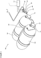
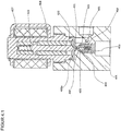
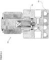
- the pressure regulator 200 comprises a housing 201 in which at least one inlet 202 followed by a high pressure chamber 203, an outlet 204 with an upstream low pressure chamber 205, flow paths 206a and 206b between the high pressure chamber 203 and the low pressure chamber 205, sealing seats 207a and 207b in the flow path 206a and 206b between the high-pressure chamber 203 and the low-pressure chamber 205, closure units 209a and 209b with an internal thread 210a and 210b for screwing the closure units 209a and 209b in the housing 201 and sealing seats 211a and 211b for sealing the closure units 209a and 209b in the housing 201 .
- the closure unit 209a and 209b comprises a valve housing 212a and 212b with a screw-in part 213a and 213b and opposite a guide part 214a and 214b.
- the screw-in part 213a and 213b has an external thread 215a and 215b for screwing to the internal thread 210a and 210b of the housing 201, an external groove 216a and 216b for the receiving bores 208a and 208b for receiving a sealing ring 217a and 217b for sealing the valve housing 212a and 212b opposite the housing 201 and a tool holder 218a and 218b for gripping by a tool for screwing the locking units 209a and 209b into the housing 201.
- the guide part 214a and 214b is provided with an external annular groove 219a and 219b for receiving a locking ring 220a and 220b for fixing the magnetic coil 221a and 221b placed on the guide part 214a and 214b.
- a valve piston 222a and 222b consisting of an armature 223a and 223b, a driver 224a and 224b, a spring 225a and 225b and a closing body 226a and 226b is arranged to be displaceable between a closed position and an open position.
- the closing body 226a and 226b is received at the first end of the magnetic armature 222a and 222b, an inner groove 227a and 227b being provided for receiving the driver 224a and 224b for the closing body 226a and 226b.
- the armature 222a and 222b is guided in the guide part 214a and 214b with little radial play, with a bore 228a and 228b for receiving the spring 224a and 224b being provided at the second end.
- a sealing surface 229a and 229b and an external groove 230a and 230b for supporting the driver 223a and 223b are implemented on the closing body 226a and 226b made of a sealing material.
- the closing body 226a and 226b can be fastened directly in the magnetic armature 222a and 222b without driver 223a and 223b, with optional ventilation of the rear surface of the driver 223a and 223b being provided.
- the closing body 226a and 226b can be designed with a groove for receiving a suitable seal, with ventilation of the rear groove surface optionally being provided.
- the housing 201 can be designed with a groove for receiving a suitable seal, with ventilation of the rear groove surface optionally being provided.
- the sealing surface cannot be implemented directly in the housing, but rather on a suitable screw-in part or on a suitable press-in part.
- a metallic closing body can be used instead of a closing body made of a suitable sealing material.
- closure units 209a and 209b can be arranged on the low-pressure side.
- the locking units 209a and 209b can be arranged at any point on the housing.
- the locking units 209a and 209b can be arranged at any point on the housing.
- a pressure regulator The mode of operation of a pressure regulator is described below: As in Fig. 2 shown, in the de-energized and non-energized state of the solenoid 221a, the spring 225a and 225b presses the armature 223a and 223b of the valve piston 222a and 222b downward, the sealing surface 229a and 229b of the closing body 226a and 226b on the sealing seat 207a and 207b in the housing 201 and thus closes the flow paths 206a and 206b between the high-pressure space 203 and the low-pressure space 205.
- the armature 223b of the valve piston 222b is raised against the active spring 225b by the activation and excitation of the magnetic coil 221b and lifts the sealing surface 229b of the closing body 226b from the sealing seat 207b in the housing 201 by the driver 224b, the flow path 206b from the high pressure chamber 203 to the Low pressure chamber 205 is exposed.
- the operating state according to FIG. 21 is implemented at high inlet pressures, with low electrical power being required to lift the valve piston due to the small size of the non-pressure compensated area and a large pressure reduction being achieved due to the small released flow diameter.
- the armature 223a of the valve piston 222a is raised against the active spring 225a by the activation and excitation of the magnetic coil 221a and lifts the sealing surface 229a of the closing body 226a by the driver 224a from the sealing seat 207a in the housing 201, the second flow path 206a from the high pressure chamber 203 to the low pressure chamber 205 is exposed.
- the operating state according to FIG. 22 is implemented at medium and low inlet pressures and, due to the large flow cross-section, a large mass flow is achieved with a small pressure reduction.
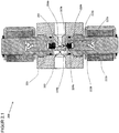
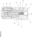
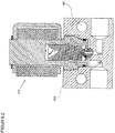
- the pressure regulator 300 comprises a housing 301 in which at least one inlet 302 with a subsequent high pressure chamber 303, an outlet 304 with an upstream low pressure chamber 305, a flow path 306 between the inlet 302 and the outlet 304, a sealing seat 307 in the flow path 306 between the high pressure chamber 303 and the low pressure chamber 305, a receiving bore 308 for receiving the locking unit 309 with an internal thread 310 for screwing the locking unit 309 in the housing 301 and a sealing seat 311 for sealing the locking unit 309 in the housing 301 are provided.
- the closure unit 309 comprises a valve housing 312 with a screw-in part 313 and opposite a guide part 314.
- the screw-in part 313 has an external thread 315 for screwing with the internal thread 310 of the housing 301, an external groove 316 for receiving a sealing ring 317 for sealing the Closure unit 309 opposite the housing 301 and a tool holder 318 for gripping by a tool for screwing the closure unit 309 into the housing 301.
- the guide part 314 is provided with an external annular groove 319 for receiving a securing ring 320 for fixing the magnetic coil 321 placed on the guide part 314.
- a valve piston 322 consisting of an armature 323, a driver 324, a spring 325 and a closing body 326, is arranged such that it can be displaced between a closed position, a first open position and a second open position.
- the Closing body 326 received, with an internal sealing seat 327 for support on the upper sealing surface 328 of the closing body 326, an internal groove 329 for receiving the driver 324, and at least one transverse bore 330 being provided.
- the armature 323 is guided in the guide part 314 with little radial play, the open end 331 being provided for receiving the spring 325.
- the closing body 326 made of a sealing material, there is an upper sealing surface 328, opposite a lower sealing surface 332 with different dimensions, an axial throttle bore 333 between the two sealing surfaces and an external groove 334 to support the driver 324 of the locking unit 309.
- the armature 323 of the valve piston 322 is raised against the active spring 325 by activating and exciting the magnetic coil 321, the lower sealing surface 332 of the closing body 326 being supported on the sealing seat 307 in the housing 301 and the sealing surface 327 of the armature 323 being supported by the upper sealing surface 329 of the closing body 326 is lifted off, whereby a flow path 306a from the high-pressure chamber 303 via the transverse bore 330 in the armature 323 and the throttle bore 333 in the closing body 326 to the low-pressure chamber 305 is exposed.
- the operating status according to Fig. 3.1 is implemented at high inlet pressures, whereby, due to the small size of the non-pressure-compensated area, a small amount of electrical power is required to lift the valve piston and, due to the small released flow diameter, a large pressure reduction is achieved.
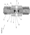
- Fig. 3.2 As shown, by increasing the excitation of the magnetic coil 321, the armature 323 of the valve piston 322 is raised further against the active spring 325, the gap 335 between the driver 324 and the closing body 326 is closed in the direction of movement of the valve piston 322 and the closing body 326 is raised by the driver 324, the lower sealing surface 332 of the closing body 326 lifted from the sealing seat 307 in the housing 301 and, when the flow path 306a is open, the flow path 306 between the high pressure chamber 303 via the sealing seat 307 in the housing 301 to the low pressure chamber 305 is exposed.
- the operating status according to Fig. 3.2 is implemented at medium and low inlet pressures and, due to the large flow cross-section, a large mass flow is achieved with a small pressure reduction.
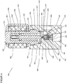
- the pressure regulator 400 comprises a housing 401 in which at least one inlet 402 with a subsequent high pressure chamber 403, an outlet 404 with an upstream low pressure chamber 405, a flow path 406 between the inlet 402 and the outlet 404, a sealing seat 407 in the flow path 406 between the high pressure chamber 403 and the low pressure chamber 405, a receiving bore 408 for receiving the closing body 409 in the housing 401 including a groove 410 for receiving a locking ring 411 to support a counter holder 412 for the first spring 413, a receiving bore 414 for receiving the locking unit 415 an inner thread 416 for screwing the closure unit 415 in the housing 401 and a sealing seat 417 for the sealing of the closure unit 415 in the housing 401 are provided.
- the closure unit 415 comprises a valve housing 418 with a screw-in part 419 and opposite a guide part 420.
- the screw-in part 419 has an external thread 421 for screwing to the inner thread 416 of the housing 401, an outer groove 422 for receiving a sealing ring 423 for sealing the locking unit 415 against the housing 401 and a tool holder 424 for gripping by a tool for screwing the locking unit 415 into the housing 401.
- the guide part 420 is provided with an external annular groove 425 for receiving a locking ring 426 for fixing the reversing solenoid 427 placed on the guide part 420.
- a magnetic armature 428 and a second spring 429 of lesser strength than the first spring 413 are arranged such that they can be displaced between a closed position, a first open position and a second open position.
- the armature 428 is guided in the guide part 420 with little radial play, the open end 432 being provided for receiving the spring 429.
- a first sealing surface 431, a second sealing surface 433 with different dimensions, an axial throttle bore 434 between the two sealing surfaces and a bore 435 for receiving the spring 413 and optionally external or internal flow channels 436 are implemented on the closing body 409 made of a sealing material.
- the closing body 409 can be designed with grooves for receiving suitable seals, with ventilation of the rear groove surfaces optionally being provided.
- the housing 401 can be designed with a groove for receiving a suitable seal, with ventilation of the rear groove surface optionally being provided.
- the sealing surface cannot be implemented directly in the housing, but rather on a suitable screw-in part or on a suitable press-in part.
- a metallic closing body can be used instead of a closing body made of a suitable sealing material.
- the spring 429 presses the armature 428 of the locking unit 415 against the closing body 409, the first sealing surface 431 of the closing body 409 being on the sealing surface 430 of the armature 428 and the second sealing surface 433 of the closing body 409 supported by the force of the spring 413 on the sealing seat 407 in the housing 401 and thus closes the flow path 406 between the high pressure chamber 403 and the low pressure chamber 405.
- armature 428 is moved against the active spring 433 by the control and excitation of the reversing solenoid 427, the second sealing surface 433 of the closing body 409 being supported by the force of the spring 413 on the sealing seat 407 in the housing 401 and the sealing surface 430 of the armature 428 being supported by the first sealing surface 431 of the closing body 409 is lifted, whereby the flow path 406a from the high pressure chamber 403 via the throttle bore 434 in the closing body 409 to the low pressure chamber 405 is exposed.
- the operating status according to Fig. 4.1 is implemented at high inlet pressures, whereby, due to the small size of the non-pressure-compensated area, a small amount of electrical power is required to lift the armature and a large pressure reduction is achieved due to the small released flow diameter.
- the armature 428 is moved against the active spring 413 by activating and exciting the reversing solenoid 427, the sealing surface 430 of the armature 428 being supported on the first sealing surface 431 of the closing body 409 and the second sealing surface 433 of the closing body 409 by the sealing seat 407 in the housing 401 is lifted off, whereby the flow path 406 is exposed from the high pressure chamber 403 via the sealing seat 407 in the housing to the low pressure chamber 405.
- the operating status according to Fig. 4.2 will be at middle and low inlet pressures and, due to the large flow cross-section, a large mass flow is achieved with a small pressure reduction.
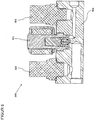
- Fig. 5 shows the pressure regulator 500 according to the invention with a modified sealing system between the high pressure chamber 501 and the low pressure chamber 502, the closing body 503 having at least one suitable receptacle 504 for a suitable seal 505, which is supported on the sealing seat 506 in the housing 507 and the armature 508 has a suitable receptacle 509 for a suitable seal 510, which is supported on the closing body 503, with optional venting of the rear groove surfaces being provided.
- the closing body has two receptacles for the two seals.
- the housing and the armature each have a receptacle for the two seals.
- the housing has two receptacles for the two seals.
- a separate sleeve can be built into the closing body to stabilize the closing body.
- the closing body can be made in several parts.
- the sealing surface cannot be implemented directly in the housing, but rather on a suitable screw-in part or on a suitable press-in part.
- a metallic closing body can be used instead of a closing body made of a suitable sealing material.
- Fig. 6 shows the pressure regulator 600 according to the invention with a modified excitation system.
- the armature 601 has an open end 602 and a closed end 603, the spring 604 being supported on an outer shoulder 605 of the open armature end 602 opposite an inner shoulder 606 of the open valve housing 607, so that the structural design of the working air gap 608 the magnetic force characteristic can be influenced in a targeted manner.
- a locking unit with a discrete switching function two-position solenoid with an open and a closed position when using an electromechanical locking unit
- a continuously switching locking unit proportional magnet with any intermediate positions between the open and closed position when using an electromechanical locking unit
- valve housing is provided with a device for mechanical opening and optionally for mechanical closing of the closing body.
- valve housing is made in several parts for better guidance of the magnetic flux.
- the armature is designed in several parts for better guidance of the magnet base or for better guidance in the valve housing.
- magnet coils can be installed one behind the other.
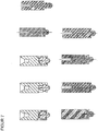
- Fig. 7 shows different possibilities for performing the driver function of the valve piston for the pressure regulator according to the invention according to one embodiment.
- Fig. 8 shows the pressure regulator 800 according to the invention with a heating system to avoid icing or excessive cooling of the pressure regulator in the case of gases with a negative Joule-Thomson coefficient in the working range of the pressure regulator, the heating being generated by means of an electric heater 801.
- Fig. 8.1 shows the pressure regulator 810 according to the invention with a heating system to avoid icing or excessive cooling of the pressure regulator in the case of gases with a negative Joule-Thomson coefficient in the working range of the pressure regulator, the heating being generated by supplying cooling water, the cooler 811 in a suitable manner is attached to the housing 812.
- Fig. 8.2 shows the pressure regulator 820 according to the invention with a heating system to avoid icing or excessive cooling of the pressure regulator in the case of gases with a negative Joule-Thomson coefficient in the operating range of the pressure regulator, the heating being generated by supplying cooling water through cooling channels 821 in the housing 822 of the pressure regulator.
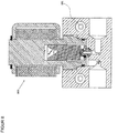
- Fig. 9 shows a control unit 900, consisting at least of the pressure regulator 901 according to the invention, a low pressure sensor 902 and optionally a high pressure sensor 903 in a common housing 904, with a corresponding heating system if required Fig. 8 Fig. 8.1 or Fig. 8.2 can be executed.
- Fig. 9.1 shows a control unit 910, consisting at least of the pressure regulator 911 according to the invention, a low-pressure sensor 912, a low-pressure safety device 913 and optionally a high-pressure sensor 914 in a common housing 915, with a corresponding heating system if required Fig. 8 , Fig. 8.1 or Fig. 8.2 can be executed.
- a spring-loaded closing body or a bursting disc can be installed as a low-pressure safety device.
- the high-pressure storage container can be filled via the control unit with suitably designed line connections.
- a check valve for filling the high-pressure storage container can be integrated into the control unit via the control unit and corresponding line connections.
- a filter element can be integrated into the control unit.
- the filling coupling for filling the high-pressure storage container can be integrated into the control unit via the control unit and corresponding line connections.
- a system shut-off valve can be integrated into the control unit on the high-pressure side or on the low-pressure side.
- a temperature-dependent safety device can be installed in the control unit.
- control unit can be integrated into the cylinder valve.
- control unit in a further embodiment, individual elements of the control unit can be accommodated in separate housings.
- the electronic control device can be attached directly to the control unit or to the pressure regulator.
- the electromechanical locking unit is considered to be a locking unit based on the functional principle of electro-magneto-mechanical energy conversion.
- a locking unit based on the functional principle of electro-hydraulic-mechanical energy conversion, electropneumatic-mechanical energy conversion, electro-mechanical energy conversion (electric motor) or a coupling of any energy conversion principles is used.
- the pressure regulator (107, 200, 300, 400, 500, 600, 800, 810, 820, 901, 911) has several flow paths (206a, 206b, 306, 306a, 406, 406a) of different cross-sections between the inlet-side high-pressure chamber (203, 303, 403, 501) and the low-pressure chamber (205, 305, 405, 502) on the outlet side
- a control opens or closes the flow paths (206b, 306a, 406a) with a small cross-section and at low pressures at high pressures or at low volume flows the flow paths (206b, 306a, 406a) with a large cross-section indirectly.
- the pressure regulator (107, 200, 300, 400, 500, 600, 800, 810, 820, 901, 911) has several flow paths of the same cross section between the inlet-side high-pressure chamber (203, 303, 403, 501) and the outlet-side low-pressure chamber (205, 305, 405, 502), a control opens or closes a few flow paths at high pressures or low volume flows and several flow paths indirectly at low pressures.
- the control opens flow paths indirectly when the working pressure is not reached and opens flow paths indirectly when the working pressure is exceeded.
Landscapes
- Physics & Mathematics (AREA)
- Fluid Mechanics (AREA)
- Engineering & Computer Science (AREA)
- General Physics & Mathematics (AREA)
- Automation & Control Theory (AREA)
- General Engineering & Computer Science (AREA)
- Combustion & Propulsion (AREA)
- Mechanical Engineering (AREA)
- Chemical & Material Sciences (AREA)
- Magnetically Actuated Valves (AREA)
- Control Of Fluid Pressure (AREA)
- Fuel-Injection Apparatus (AREA)
- Output Control And Ontrol Of Special Type Engine (AREA)
- Valve Housings (AREA)
- Fuel Cell (AREA)
- Cooling, Air Intake And Gas Exhaust, And Fuel Tank Arrangements In Propulsion Units (AREA)
- Feeding And Controlling Fuel (AREA)
Applications Claiming Priority (2)
| Application Number | Priority Date | Filing Date | Title |
|---|---|---|---|
| DE102010003016.3A DE102010003016B4 (de) | 2010-03-18 | 2010-03-18 | Druckregler zur Zuführung von Kraftstoff und Kraftstoffversorgungssystem mit einer Regeleinheit aus diesen Druckreglern |
| PCT/EP2011/054099 WO2011113922A2 (de) | 2010-03-18 | 2011-03-18 | Druckregler zur zuführung von kraftstoff und kraftstoffversorgungssystem mit einer regeleinheit aus diesen druckreglern |
Publications (2)
| Publication Number | Publication Date |
|---|---|
| EP2548089A2 EP2548089A2 (de) | 2013-01-23 |
| EP2548089B1 true EP2548089B1 (de) | 2021-05-05 |
Family
ID=44511814
Family Applications (1)
| Application Number | Title | Priority Date | Filing Date |
|---|---|---|---|
| EP11708505.0A Active EP2548089B1 (de) | 2010-03-18 | 2011-03-18 | Druckregler zur zuführung von kraftstoff und kraftstoffversorgungssystem mit einer regeleinheit aufweisend diesen druckregler |
Country Status (11)
| Country | Link |
|---|---|
| US (1) | US9880568B2 (enExample) |
| EP (1) | EP2548089B1 (enExample) |
| JP (1) | JP6005527B2 (enExample) |
| KR (1) | KR101880241B1 (enExample) |
| CN (1) | CN103109247B (enExample) |
| BR (1) | BR112012023564B1 (enExample) |
| CA (1) | CA2793038C (enExample) |
| DE (1) | DE102010003016B4 (enExample) |
| ES (1) | ES2881901T3 (enExample) |
| RU (1) | RU2559865C2 (enExample) |
| WO (1) | WO2011113922A2 (enExample) |
Families Citing this family (8)
| Publication number | Priority date | Publication date | Assignee | Title |
|---|---|---|---|---|
| DE102011118848B4 (de) * | 2011-11-18 | 2018-10-31 | BO-INNO GmbH | Gasdruckregelvorrichtung und Gehäuse einer Gasdruckregelvorrichtung |
| DE102014218818A1 (de) * | 2014-09-18 | 2016-04-07 | Continental Automotive Gmbh | Druckminderungseinrichtung für eine Vorrichtung zur Kraftstoffversorgung und Vorrichtung zur Kraftstoffversorgung |
| AT14454U3 (de) * | 2015-07-20 | 2018-08-15 | Ventrex Automotive Gmbh | Druckregler |
| AT517645A1 (de) * | 2015-07-20 | 2017-03-15 | Ventrex Automotive Gmbh | Druckregler |
| DE102016105048A1 (de) * | 2016-03-18 | 2017-09-21 | Volkswagen Aktiengesellschaft | Brennkraftmaschine und Verfahren zum Betreiben einer Brennkraftmaschine |
| DE102018113240A1 (de) * | 2018-06-04 | 2019-12-05 | Volkswagen Aktiengesellschaft | Zuführsystem zum Zuführen eines CNG- oder LNG-Kraftstoffes |
| AT17013U1 (enExample) | 2019-09-05 | 2021-02-15 | Zieger Dipl Ing Andreas | |
| DE102024204006A1 (de) | 2024-04-29 | 2025-10-30 | Robert Bosch Gesellschaft mit beschränkter Haftung | Druckregelvorrichtung für Gasmotor |
Family Cites Families (47)
| Publication number | Priority date | Publication date | Assignee | Title |
|---|---|---|---|---|
| US1228104A (en) * | 1915-08-18 | 1917-05-29 | Chaplin Fulton Mfg Company | Valve. |
| DE2937978C2 (de) * | 1979-09-20 | 1982-04-01 | Battelle-Institut E.V., 6000 Frankfurt | Gasdruckregler |
| GB2129170B (en) * | 1982-10-21 | 1986-09-24 | Secr Defence | Improvements in or relating to pressure controllers |
| JPS6158964A (ja) | 1984-08-30 | 1986-03-26 | Mitsubishi Heavy Ind Ltd | ガスエンジン |
| US4760694A (en) * | 1986-10-27 | 1988-08-02 | Rockwell International Corporation | Bi-level thruster |
| HUT54227A (en) * | 1989-05-26 | 1991-01-28 | Magyar Szenhidrogenipari | Apparatus for controlling gas utilization |
| JPH0418797U (enExample) | 1990-06-08 | 1992-02-17 | ||
| US5048790A (en) * | 1990-07-18 | 1991-09-17 | Target Rock Corporation | Self-modulating control valve for high-pressure fluid flow |
| JPH05126105A (ja) | 1991-10-16 | 1993-05-21 | Mitsubishi Nuclear Fuel Co Ltd | 空気制御ユニツト |
| JP3165214B2 (ja) | 1992-01-31 | 2001-05-14 | マツダ株式会社 | 気体燃料エンジンの燃料供給装置 |
| DE4302540C2 (de) | 1992-01-31 | 1995-05-18 | Mazda Motor | Kraftstoffzuführgerät |
| US5289811A (en) * | 1993-05-10 | 1994-03-01 | General Motors Corporation | Purge control device |
| CA2131108C (en) | 1994-08-30 | 2005-06-07 | Stephen A. Carter | Two-stage pressure regulator |
| NL9402237A (nl) * | 1994-12-29 | 1996-08-01 | Adrianus Martinus M Wildenberg | Debietregelklep. |
| CA2183478C (en) * | 1995-08-17 | 2004-02-24 | Stephen A. Carter | Digital gas metering system using tri-stable and bi-stable solenoids |
| JP3040627U (ja) | 1997-02-13 | 1997-08-26 | 甲南電機株式会社 | 減圧弁 |
| JP3787826B2 (ja) | 1997-10-09 | 2006-06-21 | 株式会社デンソー | ガスエンジンの燃料漏れ検出装置 |
| JP2000009240A (ja) | 1998-06-25 | 2000-01-11 | Kuroda Precision Ind Ltd | 流体作動機器の速度調整装置 |
| JP3675213B2 (ja) | 1999-03-01 | 2005-07-27 | トヨタ自動車株式会社 | 気体燃料供給装置 |
| JP2001066020A (ja) * | 1999-08-24 | 2001-03-16 | Denso Corp | 電磁式流量制御弁 |
| AT4536U1 (de) * | 1999-12-07 | 2001-08-27 | Steyr Daimler Puch Ag | Treibstofftankanlage für ein kraftfahrzeug und schwimmerventil |
| IT1316306B1 (it) | 2000-01-27 | 2003-04-10 | Landi Renzo Spa | Regolatore di pressione a due stadi per alimentare un motore a scoppio con carburante gassoso a pressione costante |
| US6598623B2 (en) * | 2000-08-08 | 2003-07-29 | Siemens Automotive Inc. | Fuel tank pressure control valve |
| JP2003083172A (ja) | 2001-09-12 | 2003-03-19 | Toyota Motor Corp | 液化ガス燃料供給装置 |
| DE10204746A1 (de) | 2002-02-06 | 2003-08-21 | Bosch Gmbh Robert | Gasdruckregler zur Regelung eines Druckes eines Gases |
| US6857447B2 (en) | 2002-06-10 | 2005-02-22 | Advanced Technology Materials, Inc. | Pressure-based gas delivery system and method for reducing risks associated with storage and delivery of high pressure gases |
| US20040007269A1 (en) | 2002-07-12 | 2004-01-15 | Larsen Todd W. | Inline pressure reducing regulator |
| JP2004052713A (ja) | 2002-07-23 | 2004-02-19 | Toyota Motor Corp | 内燃機関の燃料供給装置 |
| CN100360787C (zh) | 2002-08-09 | 2008-01-09 | 五十铃自动车株式会社 | 气体燃料供给装置 |
| ITMI20030091A1 (it) * | 2003-01-22 | 2004-07-23 | Cavagna Group Spa | Regolatore di pressione con manometro, particolarmente per bombole di gpl. |
| JP2005044278A (ja) | 2003-07-25 | 2005-02-17 | Nissan Motor Co Ltd | 圧力制御装置 |
| JP2005053358A (ja) * | 2003-08-05 | 2005-03-03 | Honda Motor Co Ltd | 高圧ガス貯蔵装置 |
| WO2005021348A1 (en) * | 2003-08-25 | 2005-03-10 | Bendix Commercial Vehicle Systems Llc | Drain valve |
| JP2005069456A (ja) | 2003-08-28 | 2005-03-17 | Kuroda Precision Ind Ltd | 環状オリフィス、流量制御弁または圧力制御弁 |
| CA2441641C (en) * | 2003-09-23 | 2006-01-31 | Westport Research Inc. | A high pressure gaseous fuel supply system for an internal combustion engine and a method of sealing connections between components to prevent leakage of a high pressure gaseous fuel |
| JP4203906B2 (ja) * | 2004-03-31 | 2009-01-07 | 株式会社デンソー | 電磁弁およびそれを用いた蒸発燃料処理システム |
| DE102005022693A1 (de) * | 2005-05-18 | 2006-11-23 | Hydac Fluidtechnik Gmbh | Ventil, insbesondere Proportional-Druckbegrenzungsventil |
| FR2892799B1 (fr) | 2005-10-27 | 2007-12-28 | Air Liquide | Dispositif de commande du remplissage et/ou du soutirage de fluide et reservoir comportant un tel dispositif |
| JP4744285B2 (ja) * | 2005-12-19 | 2011-08-10 | 本田技研工業株式会社 | 水素自動車のガスの使用及び補給システム |
| US7575020B2 (en) * | 2006-08-28 | 2009-08-18 | Gm Global Technology Operations, Inc. | Multi stage pressure regulator |
| DK2064474T3 (da) * | 2006-09-08 | 2014-03-31 | Artemis Intelligent Power Ltd | Ventilanordning |
| FR2905773A1 (fr) * | 2006-09-08 | 2008-03-14 | Air Liquide | Regulateur de pression et procede de regulation de pression de gaz |
| US8128377B2 (en) * | 2007-04-03 | 2012-03-06 | GM Global Technology Operations LLC | Split-pressure dual pump hydraulic fluid supply system for a multi-speed transmission and method |
| IT1391286B1 (it) | 2007-07-24 | 2011-12-01 | Ventrex Automotive Gmbh | Impianto a serbatoio e di alimentazione di combustibile per motori a combustione interna |
| CN101144437A (zh) | 2007-09-28 | 2008-03-19 | 西安易道汽车电器有限责任公司 | 摩托车发动机电控燃油喷射系统 |
| US7984890B2 (en) * | 2008-02-26 | 2011-07-26 | Incova Technologies, Inc. | Pilot operated valve with fast closing poppet |
| US20100242921A1 (en) * | 2009-03-30 | 2010-09-30 | Gregory Harper | Method And System For Controlling Fluid Flow From A Storage Tank Through A Supply Line To An End User |
-
2010
- 2010-03-18 DE DE102010003016.3A patent/DE102010003016B4/de active Active
-
2011
- 2011-03-18 CN CN201180014425.2A patent/CN103109247B/zh active Active
- 2011-03-18 KR KR1020127027124A patent/KR101880241B1/ko active Active
- 2011-03-18 CA CA2793038A patent/CA2793038C/en active Active
- 2011-03-18 WO PCT/EP2011/054099 patent/WO2011113922A2/de not_active Ceased
- 2011-03-18 ES ES11708505T patent/ES2881901T3/es active Active
- 2011-03-18 JP JP2012557562A patent/JP6005527B2/ja active Active
- 2011-03-18 US US13/635,675 patent/US9880568B2/en active Active
- 2011-03-18 EP EP11708505.0A patent/EP2548089B1/de active Active
- 2011-03-18 RU RU2012143371/28A patent/RU2559865C2/ru active
- 2011-03-18 BR BR112012023564A patent/BR112012023564B1/pt active IP Right Grant
Also Published As
| Publication number | Publication date |
|---|---|
| WO2011113922A3 (de) | 2013-03-07 |
| ES2881901T3 (es) | 2021-11-30 |
| US20130056097A1 (en) | 2013-03-07 |
| CN103109247A (zh) | 2013-05-15 |
| RU2559865C2 (ru) | 2015-08-20 |
| RU2012143371A (ru) | 2014-04-27 |
| KR101880241B1 (ko) | 2018-08-17 |
| WO2011113922A2 (de) | 2011-09-22 |
| CN103109247B (zh) | 2016-10-19 |
| KR20130014555A (ko) | 2013-02-07 |
| CA2793038A1 (en) | 2011-09-22 |
| JP6005527B2 (ja) | 2016-10-12 |
| DE102010003016A1 (de) | 2011-09-22 |
| CA2793038C (en) | 2019-04-30 |
| JP2013522528A (ja) | 2013-06-13 |
| BR112012023564B1 (pt) | 2020-04-22 |
| EP2548089A2 (de) | 2013-01-23 |
| BR112012023564A2 (pt) | 2016-08-02 |
| US9880568B2 (en) | 2018-01-30 |
| DE102010003016B4 (de) | 2018-11-08 |
Similar Documents
| Publication | Publication Date | Title |
|---|---|---|
| EP2548089B1 (de) | Druckregler zur zuführung von kraftstoff und kraftstoffversorgungssystem mit einer regeleinheit aufweisend diesen druckregler | |
| EP2653763B1 (de) | Elektromagnetisches Ventil für ein Behälterventil einer Kraftstoffversorgungsanlage | |
| EP3894736A1 (de) | Tankvorrichtung zur speicherung eines gasförmigen mediums | |
| WO2020052834A1 (de) | Ventilvorrichtung für ein gasförmiges medium und tankvorrichtung zur speicherung eines gasförmigen mediums | |
| DE102009012688B3 (de) | Ventil zum Einblasen von Gas | |
| DE102020203700A1 (de) | Ventilvorrichtung für ein Brennstoffzellensystem und Tankvorrichtung zur Speicherung eines gasförmigen Mediums | |
| EP2469137B1 (de) | Druckminderer | |
| DE102020201162A1 (de) | Tankvorrichtung zur Speicherung eines gasförmigen Mediums für ein Brennstoffzellensystem | |
| WO2022253495A1 (de) | Absperrventil für wasserstofftanksysteme, wasserstofftanksystem sowie verwendung eines absperrventils in einem wasserstofftanksystem | |
| DE102020213577A1 (de) | Tankvorrichtung zur Speicherung eines gasförmigen Mediums | |
| WO2021156083A1 (de) | Tankvorrichtung zur speicherung eines gasförmigen mediums | |
| EP4483088B1 (de) | Absperrventil sowie wasserstofftanksystem mit absperrventil | |
| DE102019211730A1 (de) | Tankvorrichtung zur Speicherung eines gasförmigen Mediums | |
| CN113906247B (zh) | 组合阀 | |
| EP1396667B1 (de) | Magnetventil | |
| WO2024028013A1 (de) | Ventilbaugruppe für einen brenngastank, brenngastank mit ventilbaugruppe sowie brenngastanksystem | |
| DE10306001A1 (de) | Doppelabsperrarmatur | |
| EP4469719A1 (de) | Absperrventil sowie wasserstofftanksystem mit absperrventil | |
| EP4244526A1 (de) | Tankvorrichtung zur speicherung eines gasförmigen mediums | |
| DE102010005411A1 (de) | Ventil | |
| EP4356030B1 (de) | Absperrventil für wasserstofftanksysteme, druckgasbehälter sowie wasserstofftanksystem | |
| DE102004020941B9 (de) | Druckregelanordnung | |
| WO2024170750A1 (de) | Druckregler für gasförmigen kraftstoff, insbesondere wasserstoffgas | |
| WO2022063489A1 (de) | Tankvorrichtung mit einer ventilvorrichtung | |
| DE102019213627A1 (de) | Tankvorrichtung zur Speicherung eines gasförmigen Mediums |
Legal Events
| Date | Code | Title | Description |
|---|---|---|---|
| PUAI | Public reference made under article 153(3) epc to a published international application that has entered the european phase |
Free format text: ORIGINAL CODE: 0009012 |
|
| 17P | Request for examination filed |
Effective date: 20121010 |
|
| AK | Designated contracting states |
Kind code of ref document: A2 Designated state(s): AL AT BE BG CH CY CZ DE DK EE ES FI FR GB GR HR HU IE IS IT LI LT LU LV MC MK MT NL NO PL PT RO RS SE SI SK SM TR |
|
| R17D | Deferred search report published (corrected) |
Effective date: 20130307 |
|
| DAX | Request for extension of the european patent (deleted) | ||
| 17Q | First examination report despatched |
Effective date: 20160812 |
|
| STAA | Information on the status of an ep patent application or granted ep patent |
Free format text: STATUS: EXAMINATION IS IN PROGRESS |
|
| REG | Reference to a national code |
Ref country code: DE Ref legal event code: R079 Ref document number: 502011017132 Country of ref document: DE Free format text: PREVIOUS MAIN CLASS: G05D0016040000 Ipc: G05D0016200000 |
|
| GRAP | Despatch of communication of intention to grant a patent |
Free format text: ORIGINAL CODE: EPIDOSNIGR1 |
|
| STAA | Information on the status of an ep patent application or granted ep patent |
Free format text: STATUS: GRANT OF PATENT IS INTENDED |
|
| RIC1 | Information provided on ipc code assigned before grant |
Ipc: G05D 16/20 20060101AFI20200922BHEP |
|
| INTG | Intention to grant announced |
Effective date: 20201012 |
|
| RAP1 | Party data changed (applicant data changed or rights of an application transferred) |
Owner name: HYPTECH GMBH |
|
| GRAS | Grant fee paid |
Free format text: ORIGINAL CODE: EPIDOSNIGR3 |
|
| GRAA | (expected) grant |
Free format text: ORIGINAL CODE: 0009210 |
|
| STAA | Information on the status of an ep patent application or granted ep patent |
Free format text: STATUS: THE PATENT HAS BEEN GRANTED |
|
| RAP3 | Party data changed (applicant data changed or rights of an application transferred) |
Owner name: HYPTEC GMBH |
|
| AK | Designated contracting states |
Kind code of ref document: B1 Designated state(s): AL AT BE BG CH CY CZ DE DK EE ES FI FR GB GR HR HU IE IS IT LI LT LU LV MC MK MT NL NO PL PT RO RS SE SI SK SM TR |
|
| REG | Reference to a national code |
Ref country code: GB Ref legal event code: FG4D Free format text: NOT ENGLISH |
|
| REG | Reference to a national code |
Ref country code: CH Ref legal event code: EP |
|
| REG | Reference to a national code |
Ref country code: AT Ref legal event code: REF Ref document number: 1390608 Country of ref document: AT Kind code of ref document: T Effective date: 20210515 |
|
| REG | Reference to a national code |
Ref country code: DE Ref legal event code: R096 Ref document number: 502011017132 Country of ref document: DE |
|
| REG | Reference to a national code |
Ref country code: IE Ref legal event code: FG4D Free format text: LANGUAGE OF EP DOCUMENT: GERMAN |
|
| REG | Reference to a national code |
Ref country code: SE Ref legal event code: TRGR |
|
| REG | Reference to a national code |
Ref country code: LT Ref legal event code: MG9D |
|
| REG | Reference to a national code |
Ref country code: NO Ref legal event code: T2 Effective date: 20210505 |
|
| PG25 | Lapsed in a contracting state [announced via postgrant information from national office to epo] |
Ref country code: FI Free format text: LAPSE BECAUSE OF FAILURE TO SUBMIT A TRANSLATION OF THE DESCRIPTION OR TO PAY THE FEE WITHIN THE PRESCRIBED TIME-LIMIT Effective date: 20210505 Ref country code: LT Free format text: LAPSE BECAUSE OF FAILURE TO SUBMIT A TRANSLATION OF THE DESCRIPTION OR TO PAY THE FEE WITHIN THE PRESCRIBED TIME-LIMIT Effective date: 20210505 Ref country code: HR Free format text: LAPSE BECAUSE OF FAILURE TO SUBMIT A TRANSLATION OF THE DESCRIPTION OR TO PAY THE FEE WITHIN THE PRESCRIBED TIME-LIMIT Effective date: 20210505 Ref country code: BG Free format text: LAPSE BECAUSE OF FAILURE TO SUBMIT A TRANSLATION OF THE DESCRIPTION OR TO PAY THE FEE WITHIN THE PRESCRIBED TIME-LIMIT Effective date: 20210805 |
|
| PG25 | Lapsed in a contracting state [announced via postgrant information from national office to epo] |
Ref country code: PL Free format text: LAPSE BECAUSE OF FAILURE TO SUBMIT A TRANSLATION OF THE DESCRIPTION OR TO PAY THE FEE WITHIN THE PRESCRIBED TIME-LIMIT Effective date: 20210505 Ref country code: PT Free format text: LAPSE BECAUSE OF FAILURE TO SUBMIT A TRANSLATION OF THE DESCRIPTION OR TO PAY THE FEE WITHIN THE PRESCRIBED TIME-LIMIT Effective date: 20210906 Ref country code: LV Free format text: LAPSE BECAUSE OF FAILURE TO SUBMIT A TRANSLATION OF THE DESCRIPTION OR TO PAY THE FEE WITHIN THE PRESCRIBED TIME-LIMIT Effective date: 20210505 Ref country code: GR Free format text: LAPSE BECAUSE OF FAILURE TO SUBMIT A TRANSLATION OF THE DESCRIPTION OR TO PAY THE FEE WITHIN THE PRESCRIBED TIME-LIMIT Effective date: 20210806 Ref country code: IS Free format text: LAPSE BECAUSE OF FAILURE TO SUBMIT A TRANSLATION OF THE DESCRIPTION OR TO PAY THE FEE WITHIN THE PRESCRIBED TIME-LIMIT Effective date: 20210905 Ref country code: RS Free format text: LAPSE BECAUSE OF FAILURE TO SUBMIT A TRANSLATION OF THE DESCRIPTION OR TO PAY THE FEE WITHIN THE PRESCRIBED TIME-LIMIT Effective date: 20210505 |
|
| REG | Reference to a national code |
Ref country code: ES Ref legal event code: FG2A Ref document number: 2881901 Country of ref document: ES Kind code of ref document: T3 Effective date: 20211130 |
|
| REG | Reference to a national code |
Ref country code: NL Ref legal event code: MP Effective date: 20210505 |
|
| PG25 | Lapsed in a contracting state [announced via postgrant information from national office to epo] |
Ref country code: NL Free format text: LAPSE BECAUSE OF FAILURE TO SUBMIT A TRANSLATION OF THE DESCRIPTION OR TO PAY THE FEE WITHIN THE PRESCRIBED TIME-LIMIT Effective date: 20210505 |
|
| PG25 | Lapsed in a contracting state [announced via postgrant information from national office to epo] |
Ref country code: DK Free format text: LAPSE BECAUSE OF FAILURE TO SUBMIT A TRANSLATION OF THE DESCRIPTION OR TO PAY THE FEE WITHIN THE PRESCRIBED TIME-LIMIT Effective date: 20210505 Ref country code: EE Free format text: LAPSE BECAUSE OF FAILURE TO SUBMIT A TRANSLATION OF THE DESCRIPTION OR TO PAY THE FEE WITHIN THE PRESCRIBED TIME-LIMIT Effective date: 20210505 Ref country code: CZ Free format text: LAPSE BECAUSE OF FAILURE TO SUBMIT A TRANSLATION OF THE DESCRIPTION OR TO PAY THE FEE WITHIN THE PRESCRIBED TIME-LIMIT Effective date: 20210505 Ref country code: SM Free format text: LAPSE BECAUSE OF FAILURE TO SUBMIT A TRANSLATION OF THE DESCRIPTION OR TO PAY THE FEE WITHIN THE PRESCRIBED TIME-LIMIT Effective date: 20210505 Ref country code: SK Free format text: LAPSE BECAUSE OF FAILURE TO SUBMIT A TRANSLATION OF THE DESCRIPTION OR TO PAY THE FEE WITHIN THE PRESCRIBED TIME-LIMIT Effective date: 20210505 Ref country code: RO Free format text: LAPSE BECAUSE OF FAILURE TO SUBMIT A TRANSLATION OF THE DESCRIPTION OR TO PAY THE FEE WITHIN THE PRESCRIBED TIME-LIMIT Effective date: 20210505 |
|
| REG | Reference to a national code |
Ref country code: DE Ref legal event code: R097 Ref document number: 502011017132 Country of ref document: DE |
|
| PLBE | No opposition filed within time limit |
Free format text: ORIGINAL CODE: 0009261 |
|
| STAA | Information on the status of an ep patent application or granted ep patent |
Free format text: STATUS: NO OPPOSITION FILED WITHIN TIME LIMIT |
|
| 26N | No opposition filed |
Effective date: 20220208 |
|
| PG25 | Lapsed in a contracting state [announced via postgrant information from national office to epo] |
Ref country code: IS Free format text: LAPSE BECAUSE OF FAILURE TO SUBMIT A TRANSLATION OF THE DESCRIPTION OR TO PAY THE FEE WITHIN THE PRESCRIBED TIME-LIMIT Effective date: 20210905 Ref country code: AL Free format text: LAPSE BECAUSE OF FAILURE TO SUBMIT A TRANSLATION OF THE DESCRIPTION OR TO PAY THE FEE WITHIN THE PRESCRIBED TIME-LIMIT Effective date: 20210505 |
|
| PG25 | Lapsed in a contracting state [announced via postgrant information from national office to epo] |
Ref country code: MC Free format text: LAPSE BECAUSE OF FAILURE TO SUBMIT A TRANSLATION OF THE DESCRIPTION OR TO PAY THE FEE WITHIN THE PRESCRIBED TIME-LIMIT Effective date: 20210505 |
|
| REG | Reference to a national code |
Ref country code: CH Ref legal event code: PL |
|
| REG | Reference to a national code |
Ref country code: BE Ref legal event code: MM Effective date: 20220331 |
|
| PG25 | Lapsed in a contracting state [announced via postgrant information from national office to epo] |
Ref country code: LU Free format text: LAPSE BECAUSE OF NON-PAYMENT OF DUE FEES Effective date: 20220318 Ref country code: LI Free format text: LAPSE BECAUSE OF NON-PAYMENT OF DUE FEES Effective date: 20220331 Ref country code: IE Free format text: LAPSE BECAUSE OF NON-PAYMENT OF DUE FEES Effective date: 20220318 Ref country code: CH Free format text: LAPSE BECAUSE OF NON-PAYMENT OF DUE FEES Effective date: 20220331 |
|
| PG25 | Lapsed in a contracting state [announced via postgrant information from national office to epo] |
Ref country code: BE Free format text: LAPSE BECAUSE OF NON-PAYMENT OF DUE FEES Effective date: 20220331 |
|
| REG | Reference to a national code |
Ref country code: AT Ref legal event code: MM01 Ref document number: 1390608 Country of ref document: AT Kind code of ref document: T Effective date: 20220318 |
|
| PG25 | Lapsed in a contracting state [announced via postgrant information from national office to epo] |
Ref country code: AT Free format text: LAPSE BECAUSE OF NON-PAYMENT OF DUE FEES Effective date: 20220318 |
|
| PG25 | Lapsed in a contracting state [announced via postgrant information from national office to epo] |
Ref country code: HU Free format text: LAPSE BECAUSE OF FAILURE TO SUBMIT A TRANSLATION OF THE DESCRIPTION OR TO PAY THE FEE WITHIN THE PRESCRIBED TIME-LIMIT; INVALID AB INITIO Effective date: 20110318 |
|
| PG25 | Lapsed in a contracting state [announced via postgrant information from national office to epo] |
Ref country code: MK Free format text: LAPSE BECAUSE OF FAILURE TO SUBMIT A TRANSLATION OF THE DESCRIPTION OR TO PAY THE FEE WITHIN THE PRESCRIBED TIME-LIMIT Effective date: 20210505 Ref country code: CY Free format text: LAPSE BECAUSE OF FAILURE TO SUBMIT A TRANSLATION OF THE DESCRIPTION OR TO PAY THE FEE WITHIN THE PRESCRIBED TIME-LIMIT Effective date: 20210505 |
|
| PG25 | Lapsed in a contracting state [announced via postgrant information from national office to epo] |
Ref country code: TR Free format text: LAPSE BECAUSE OF FAILURE TO SUBMIT A TRANSLATION OF THE DESCRIPTION OR TO PAY THE FEE WITHIN THE PRESCRIBED TIME-LIMIT Effective date: 20210505 |
|
| REG | Reference to a national code |
Ref country code: DE Ref legal event code: R082 Ref document number: 502011017132 Country of ref document: DE Representative=s name: DR. SOLF & ZAPF PATENT- UND RECHTSANWALTS PART, DE Ref country code: DE Ref legal event code: R081 Ref document number: 502011017132 Country of ref document: DE Owner name: VOSS FLUID GMBH, DE Free format text: FORMER OWNER: HYPTEC GMBH, LEBRING, AT |
|
| PG25 | Lapsed in a contracting state [announced via postgrant information from national office to epo] |
Ref country code: MT Free format text: LAPSE BECAUSE OF FAILURE TO SUBMIT A TRANSLATION OF THE DESCRIPTION OR TO PAY THE FEE WITHIN THE PRESCRIBED TIME-LIMIT Effective date: 20210505 |
|
| REG | Reference to a national code |
Ref country code: ES Ref legal event code: PC2A Owner name: VOSS FLUID GMBH Effective date: 20241113 |
|
| PGFP | Annual fee paid to national office [announced via postgrant information from national office to epo] |
Ref country code: SE Payment date: 20250220 Year of fee payment: 15 |
|
| PGFP | Annual fee paid to national office [announced via postgrant information from national office to epo] |
Ref country code: NO Payment date: 20250213 Year of fee payment: 15 |
|
| PGFP | Annual fee paid to national office [announced via postgrant information from national office to epo] |
Ref country code: FR Payment date: 20250217 Year of fee payment: 15 |
|
| PGFP | Annual fee paid to national office [announced via postgrant information from national office to epo] |
Ref country code: IT Payment date: 20250212 Year of fee payment: 15 Ref country code: GB Payment date: 20250221 Year of fee payment: 15 |
|
| PGFP | Annual fee paid to national office [announced via postgrant information from national office to epo] |
Ref country code: DE Payment date: 20250526 Year of fee payment: 15 |
|
| PGFP | Annual fee paid to national office [announced via postgrant information from national office to epo] |
Ref country code: ES Payment date: 20250409 Year of fee payment: 15 |