EP2548089B1 - Druckregler zur zuführung von kraftstoff und kraftstoffversorgungssystem mit einer regeleinheit aufweisend diesen druckregler - Google Patents
Druckregler zur zuführung von kraftstoff und kraftstoffversorgungssystem mit einer regeleinheit aufweisend diesen druckregler Download PDFInfo
- Publication number
- EP2548089B1 EP2548089B1 EP11708505.0A EP11708505A EP2548089B1 EP 2548089 B1 EP2548089 B1 EP 2548089B1 EP 11708505 A EP11708505 A EP 11708505A EP 2548089 B1 EP2548089 B1 EP 2548089B1
- Authority
- EP
- European Patent Office
- Prior art keywords
- pressure
- pressure regulator
- flow paths
- closing body
- housing
- Prior art date
- Legal status (The legal status is an assumption and is not a legal conclusion. Google has not performed a legal analysis and makes no representation as to the accuracy of the status listed.)
- Active
Links
Images


Classifications
-
- G—PHYSICS
- G05—CONTROLLING; REGULATING
- G05D—SYSTEMS FOR CONTROLLING OR REGULATING NON-ELECTRIC VARIABLES
- G05D16/00—Control of fluid pressure
- G05D16/20—Control of fluid pressure characterised by the use of electric means
- G05D16/2006—Control of fluid pressure characterised by the use of electric means with direct action of electric energy on controlling means
- G05D16/2013—Control of fluid pressure characterised by the use of electric means with direct action of electric energy on controlling means using throttling means as controlling means
- G05D16/2026—Control of fluid pressure characterised by the use of electric means with direct action of electric energy on controlling means using throttling means as controlling means with a plurality of throttling means
- G05D16/204—Control of fluid pressure characterised by the use of electric means with direct action of electric energy on controlling means using throttling means as controlling means with a plurality of throttling means the plurality of throttling means being arranged in parallel
-
- F—MECHANICAL ENGINEERING; LIGHTING; HEATING; WEAPONS; BLASTING
- F02—COMBUSTION ENGINES; HOT-GAS OR COMBUSTION-PRODUCT ENGINE PLANTS
- F02M—SUPPLYING COMBUSTION ENGINES IN GENERAL WITH COMBUSTIBLE MIXTURES OR CONSTITUENTS THEREOF
- F02M37/00—Apparatus or systems for feeding liquid fuel from storage containers to carburettors or fuel-injection apparatus; Arrangements for purifying liquid fuel specially adapted for, or arranged on, internal-combustion engines
-
- G—PHYSICS
- G05—CONTROLLING; REGULATING
- G05D—SYSTEMS FOR CONTROLLING OR REGULATING NON-ELECTRIC VARIABLES
- G05D16/00—Control of fluid pressure
- G05D16/20—Control of fluid pressure characterised by the use of electric means
- G05D16/2006—Control of fluid pressure characterised by the use of electric means with direct action of electric energy on controlling means
- G05D16/2013—Control of fluid pressure characterised by the use of electric means with direct action of electric energy on controlling means using throttling means as controlling means
- G05D16/2022—Control of fluid pressure characterised by the use of electric means with direct action of electric energy on controlling means using throttling means as controlling means actuated by a proportional solenoid
-
- Y—GENERAL TAGGING OF NEW TECHNOLOGICAL DEVELOPMENTS; GENERAL TAGGING OF CROSS-SECTIONAL TECHNOLOGIES SPANNING OVER SEVERAL SECTIONS OF THE IPC; TECHNICAL SUBJECTS COVERED BY FORMER USPC CROSS-REFERENCE ART COLLECTIONS [XRACs] AND DIGESTS
- Y10—TECHNICAL SUBJECTS COVERED BY FORMER USPC
- Y10T—TECHNICAL SUBJECTS COVERED BY FORMER US CLASSIFICATION
- Y10T137/00—Fluid handling
- Y10T137/0318—Processes
-
- Y—GENERAL TAGGING OF NEW TECHNOLOGICAL DEVELOPMENTS; GENERAL TAGGING OF CROSS-SECTIONAL TECHNOLOGIES SPANNING OVER SEVERAL SECTIONS OF THE IPC; TECHNICAL SUBJECTS COVERED BY FORMER USPC CROSS-REFERENCE ART COLLECTIONS [XRACs] AND DIGESTS
- Y10—TECHNICAL SUBJECTS COVERED BY FORMER USPC
- Y10T—TECHNICAL SUBJECTS COVERED BY FORMER US CLASSIFICATION
- Y10T137/00—Fluid handling
- Y10T137/7722—Line condition change responsive valves
- Y10T137/7781—With separate connected fluid reactor surface
- Y10T137/7793—With opening bias [e.g., pressure regulator]
- Y10T137/7804—Main flow through isolated reactor chamber
-
- Y—GENERAL TAGGING OF NEW TECHNOLOGICAL DEVELOPMENTS; GENERAL TAGGING OF CROSS-SECTIONAL TECHNOLOGIES SPANNING OVER SEVERAL SECTIONS OF THE IPC; TECHNICAL SUBJECTS COVERED BY FORMER USPC CROSS-REFERENCE ART COLLECTIONS [XRACs] AND DIGESTS
- Y10—TECHNICAL SUBJECTS COVERED BY FORMER USPC
- Y10T—TECHNICAL SUBJECTS COVERED BY FORMER US CLASSIFICATION
- Y10T137/00—Fluid handling
- Y10T137/8593—Systems
- Y10T137/87265—Dividing into parallel flow paths with recombining
- Y10T137/87298—Having digital flow controller
- Y10T137/87306—Having plural branches under common control for separate valve actuators
- Y10T137/87314—Electromagnetic or electric control [e.g., digital control, bistable electro control, etc.]
Definitions
- the present invention relates to a fuel supply system and a pressure regulator for a fuel supply system for supplying fuel from a reservoir to a consumer, and a method for pressure regulation.
- the pressure regulator has the task of reducing the stored gas from the storage pressure to a predetermined working pressure, which is mostly dependent on the operating conditions of the vehicle, and is therefore an essential element of a fuel supply system.
- DE 29 37 978 A1 discloses a gas pressure regulator with a pressure gauge which controls solenoid valves to the pressure equalization outlets as a function of the ratio of the setpoint to the actual value of the gas space pressure.
- JP 2001/066020 A discloses an electromagnetic flow control valve for air conditioning systems that have different optimal flow rates of refrigerant without modifying basic specifications for flow rate characteristics.
- DE 10 2007 039 925 A1 discloses a pressure regulator wherein multiple valve stages are used to service low flow rates and to maximize a damping ratio of the regulator.
- U.S. 5,048,790 shows a self-modulating control valve.
- a disk arrangement is lifted through various pressure chambers in order to open the valve.
- US 2005/0217734 A1 shows an electromagnetic valve.
- the electromagnetic valve connects a fuel tank with a canister.
- a solenoid When a solenoid is actuated, a first valve body 50 is raised and a fluid passage between the fuel tank and canister is opened.
- the force of attraction of a second valve body in the direction of a second valve seat also drops.
- the second valve body is then pressed by a spring in the direction of the first valve body 50, as a result of which a larger opening is released.
- a flow path is implemented between the inlet-side high-pressure chamber and the outlet-side low-pressure chamber, with one closure unit in the case of single-stage pressure regulators and two or more closure units arranged one behind the other in the one flow path between the two-stage or multi-stage pressure regulators
- the inlet-side high-pressure chamber and the outlet-side low-pressure chamber are designed and open and close the flow path in a suitable manner.
- the transition between the two modes of operation is determined by the cross section of the flow paths and by the actuation force of the closure unit.
- the flow paths can be arranged next to one another.
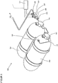
- a fuel supply system 100 in particular a gas-powered motor vehicle, for the supply of a consumer 101, with gaseous fuel such as natural gas, methane, biogas, hydrogen or the like from one or more storage containers 102 including tank valve 103, which is arranged during refueling via a filling side Filling coupling 104 with an integrated non-return valve and an adjoining gas supply line 105 can be supplied with fuel gas.
- a control unit 106 at least consisting of a pressure regulator 107, a high pressure sensor 108, a low pressure sensor 109 and safety devices 110 (high pressure fuse, low pressure fuse, thermal fuse) is also provided for the removal of the accumulator pressure and the working pressure is generated, controlled.
- the refueling starting from the filling coupling arranged on the filling side with an integrated non-return valve, can be carried out via the Control unit take place, with optionally a check valve and optionally a filter as well as suitable line connections to the filling coupling and to the high-pressure storage tanks are arranged on the inlet side.
- the filling coupling with an integrated non-return valve can be integrated into the control unit.
- a system shut-off valve can be integrated into the control unit.
- the pressure regulator can be integrated into the cylinder valve.
- control unit can be integrated into the cylinder valve.
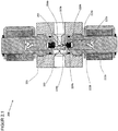
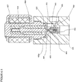
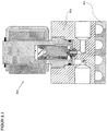
- the pressure regulator 200 comprises a housing 201 in which at least one inlet 202 followed by a high pressure chamber 203, an outlet 204 with an upstream low pressure chamber 205, flow paths 206a and 206b between the high pressure chamber 203 and the low pressure chamber 205, sealing seats 207a and 207b in the flow path 206a and 206b between the high-pressure chamber 203 and the low-pressure chamber 205, closure units 209a and 209b with an internal thread 210a and 210b for screwing the closure units 209a and 209b in the housing 201 and sealing seats 211a and 211b for sealing the closure units 209a and 209b in the housing 201 .
- the closure unit 209a and 209b comprises a valve housing 212a and 212b with a screw-in part 213a and 213b and opposite a guide part 214a and 214b.
- the screw-in part 213a and 213b has an external thread 215a and 215b for screwing to the internal thread 210a and 210b of the housing 201, an external groove 216a and 216b for the receiving bores 208a and 208b for receiving a sealing ring 217a and 217b for sealing the valve housing 212a and 212b opposite the housing 201 and a tool holder 218a and 218b for gripping by a tool for screwing the locking units 209a and 209b into the housing 201.
- the guide part 214a and 214b is provided with an external annular groove 219a and 219b for receiving a locking ring 220a and 220b for fixing the magnetic coil 221a and 221b placed on the guide part 214a and 214b.
- a valve piston 222a and 222b consisting of an armature 223a and 223b, a driver 224a and 224b, a spring 225a and 225b and a closing body 226a and 226b is arranged to be displaceable between a closed position and an open position.
- the closing body 226a and 226b is received at the first end of the magnetic armature 222a and 222b, an inner groove 227a and 227b being provided for receiving the driver 224a and 224b for the closing body 226a and 226b.
- the armature 222a and 222b is guided in the guide part 214a and 214b with little radial play, with a bore 228a and 228b for receiving the spring 224a and 224b being provided at the second end.
- a sealing surface 229a and 229b and an external groove 230a and 230b for supporting the driver 223a and 223b are implemented on the closing body 226a and 226b made of a sealing material.
- the closing body 226a and 226b can be fastened directly in the magnetic armature 222a and 222b without driver 223a and 223b, with optional ventilation of the rear surface of the driver 223a and 223b being provided.
- the closing body 226a and 226b can be designed with a groove for receiving a suitable seal, with ventilation of the rear groove surface optionally being provided.
- the housing 201 can be designed with a groove for receiving a suitable seal, with ventilation of the rear groove surface optionally being provided.
- the sealing surface cannot be implemented directly in the housing, but rather on a suitable screw-in part or on a suitable press-in part.
- a metallic closing body can be used instead of a closing body made of a suitable sealing material.
- closure units 209a and 209b can be arranged on the low-pressure side.
- the locking units 209a and 209b can be arranged at any point on the housing.
- the locking units 209a and 209b can be arranged at any point on the housing.
- a pressure regulator The mode of operation of a pressure regulator is described below: As in Fig. 2 shown, in the de-energized and non-energized state of the solenoid 221a, the spring 225a and 225b presses the armature 223a and 223b of the valve piston 222a and 222b downward, the sealing surface 229a and 229b of the closing body 226a and 226b on the sealing seat 207a and 207b in the housing 201 and thus closes the flow paths 206a and 206b between the high-pressure space 203 and the low-pressure space 205.
- the armature 223b of the valve piston 222b is raised against the active spring 225b by the activation and excitation of the magnetic coil 221b and lifts the sealing surface 229b of the closing body 226b from the sealing seat 207b in the housing 201 by the driver 224b, the flow path 206b from the high pressure chamber 203 to the Low pressure chamber 205 is exposed.
- the operating state according to FIG. 21 is implemented at high inlet pressures, with low electrical power being required to lift the valve piston due to the small size of the non-pressure compensated area and a large pressure reduction being achieved due to the small released flow diameter.
- the armature 223a of the valve piston 222a is raised against the active spring 225a by the activation and excitation of the magnetic coil 221a and lifts the sealing surface 229a of the closing body 226a by the driver 224a from the sealing seat 207a in the housing 201, the second flow path 206a from the high pressure chamber 203 to the low pressure chamber 205 is exposed.
- the operating state according to FIG. 22 is implemented at medium and low inlet pressures and, due to the large flow cross-section, a large mass flow is achieved with a small pressure reduction.
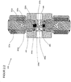
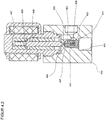
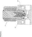
- the pressure regulator 300 comprises a housing 301 in which at least one inlet 302 with a subsequent high pressure chamber 303, an outlet 304 with an upstream low pressure chamber 305, a flow path 306 between the inlet 302 and the outlet 304, a sealing seat 307 in the flow path 306 between the high pressure chamber 303 and the low pressure chamber 305, a receiving bore 308 for receiving the locking unit 309 with an internal thread 310 for screwing the locking unit 309 in the housing 301 and a sealing seat 311 for sealing the locking unit 309 in the housing 301 are provided.
- the closure unit 309 comprises a valve housing 312 with a screw-in part 313 and opposite a guide part 314.
- the screw-in part 313 has an external thread 315 for screwing with the internal thread 310 of the housing 301, an external groove 316 for receiving a sealing ring 317 for sealing the Closure unit 309 opposite the housing 301 and a tool holder 318 for gripping by a tool for screwing the closure unit 309 into the housing 301.
- the guide part 314 is provided with an external annular groove 319 for receiving a securing ring 320 for fixing the magnetic coil 321 placed on the guide part 314.
- a valve piston 322 consisting of an armature 323, a driver 324, a spring 325 and a closing body 326, is arranged such that it can be displaced between a closed position, a first open position and a second open position.
- the Closing body 326 received, with an internal sealing seat 327 for support on the upper sealing surface 328 of the closing body 326, an internal groove 329 for receiving the driver 324, and at least one transverse bore 330 being provided.
- the armature 323 is guided in the guide part 314 with little radial play, the open end 331 being provided for receiving the spring 325.
- the closing body 326 made of a sealing material, there is an upper sealing surface 328, opposite a lower sealing surface 332 with different dimensions, an axial throttle bore 333 between the two sealing surfaces and an external groove 334 to support the driver 324 of the locking unit 309.
- the armature 323 of the valve piston 322 is raised against the active spring 325 by activating and exciting the magnetic coil 321, the lower sealing surface 332 of the closing body 326 being supported on the sealing seat 307 in the housing 301 and the sealing surface 327 of the armature 323 being supported by the upper sealing surface 329 of the closing body 326 is lifted off, whereby a flow path 306a from the high-pressure chamber 303 via the transverse bore 330 in the armature 323 and the throttle bore 333 in the closing body 326 to the low-pressure chamber 305 is exposed.
- the operating status according to Fig. 3.1 is implemented at high inlet pressures, whereby, due to the small size of the non-pressure-compensated area, a small amount of electrical power is required to lift the valve piston and, due to the small released flow diameter, a large pressure reduction is achieved.
- Fig. 3.2 As shown, by increasing the excitation of the magnetic coil 321, the armature 323 of the valve piston 322 is raised further against the active spring 325, the gap 335 between the driver 324 and the closing body 326 is closed in the direction of movement of the valve piston 322 and the closing body 326 is raised by the driver 324, the lower sealing surface 332 of the closing body 326 lifted from the sealing seat 307 in the housing 301 and, when the flow path 306a is open, the flow path 306 between the high pressure chamber 303 via the sealing seat 307 in the housing 301 to the low pressure chamber 305 is exposed.
- the operating status according to Fig. 3.2 is implemented at medium and low inlet pressures and, due to the large flow cross-section, a large mass flow is achieved with a small pressure reduction.
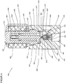
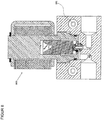
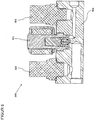
- the pressure regulator 400 comprises a housing 401 in which at least one inlet 402 with a subsequent high pressure chamber 403, an outlet 404 with an upstream low pressure chamber 405, a flow path 406 between the inlet 402 and the outlet 404, a sealing seat 407 in the flow path 406 between the high pressure chamber 403 and the low pressure chamber 405, a receiving bore 408 for receiving the closing body 409 in the housing 401 including a groove 410 for receiving a locking ring 411 to support a counter holder 412 for the first spring 413, a receiving bore 414 for receiving the locking unit 415 an inner thread 416 for screwing the closure unit 415 in the housing 401 and a sealing seat 417 for the sealing of the closure unit 415 in the housing 401 are provided.
- the closure unit 415 comprises a valve housing 418 with a screw-in part 419 and opposite a guide part 420.
- the screw-in part 419 has an external thread 421 for screwing to the inner thread 416 of the housing 401, an outer groove 422 for receiving a sealing ring 423 for sealing the locking unit 415 against the housing 401 and a tool holder 424 for gripping by a tool for screwing the locking unit 415 into the housing 401.
- the guide part 420 is provided with an external annular groove 425 for receiving a locking ring 426 for fixing the reversing solenoid 427 placed on the guide part 420.
- a magnetic armature 428 and a second spring 429 of lesser strength than the first spring 413 are arranged such that they can be displaced between a closed position, a first open position and a second open position.
- the armature 428 is guided in the guide part 420 with little radial play, the open end 432 being provided for receiving the spring 429.
- a first sealing surface 431, a second sealing surface 433 with different dimensions, an axial throttle bore 434 between the two sealing surfaces and a bore 435 for receiving the spring 413 and optionally external or internal flow channels 436 are implemented on the closing body 409 made of a sealing material.
- the closing body 409 can be designed with grooves for receiving suitable seals, with ventilation of the rear groove surfaces optionally being provided.
- the housing 401 can be designed with a groove for receiving a suitable seal, with ventilation of the rear groove surface optionally being provided.
- the sealing surface cannot be implemented directly in the housing, but rather on a suitable screw-in part or on a suitable press-in part.
- a metallic closing body can be used instead of a closing body made of a suitable sealing material.
- the spring 429 presses the armature 428 of the locking unit 415 against the closing body 409, the first sealing surface 431 of the closing body 409 being on the sealing surface 430 of the armature 428 and the second sealing surface 433 of the closing body 409 supported by the force of the spring 413 on the sealing seat 407 in the housing 401 and thus closes the flow path 406 between the high pressure chamber 403 and the low pressure chamber 405.
- armature 428 is moved against the active spring 433 by the control and excitation of the reversing solenoid 427, the second sealing surface 433 of the closing body 409 being supported by the force of the spring 413 on the sealing seat 407 in the housing 401 and the sealing surface 430 of the armature 428 being supported by the first sealing surface 431 of the closing body 409 is lifted, whereby the flow path 406a from the high pressure chamber 403 via the throttle bore 434 in the closing body 409 to the low pressure chamber 405 is exposed.
- the operating status according to Fig. 4.1 is implemented at high inlet pressures, whereby, due to the small size of the non-pressure-compensated area, a small amount of electrical power is required to lift the armature and a large pressure reduction is achieved due to the small released flow diameter.
- the armature 428 is moved against the active spring 413 by activating and exciting the reversing solenoid 427, the sealing surface 430 of the armature 428 being supported on the first sealing surface 431 of the closing body 409 and the second sealing surface 433 of the closing body 409 by the sealing seat 407 in the housing 401 is lifted off, whereby the flow path 406 is exposed from the high pressure chamber 403 via the sealing seat 407 in the housing to the low pressure chamber 405.
- the operating status according to Fig. 4.2 will be at middle and low inlet pressures and, due to the large flow cross-section, a large mass flow is achieved with a small pressure reduction.
- Fig. 5 shows the pressure regulator 500 according to the invention with a modified sealing system between the high pressure chamber 501 and the low pressure chamber 502, the closing body 503 having at least one suitable receptacle 504 for a suitable seal 505, which is supported on the sealing seat 506 in the housing 507 and the armature 508 has a suitable receptacle 509 for a suitable seal 510, which is supported on the closing body 503, with optional venting of the rear groove surfaces being provided.
- the closing body has two receptacles for the two seals.
- the housing and the armature each have a receptacle for the two seals.
- the housing has two receptacles for the two seals.
- a separate sleeve can be built into the closing body to stabilize the closing body.
- the closing body can be made in several parts.
- the sealing surface cannot be implemented directly in the housing, but rather on a suitable screw-in part or on a suitable press-in part.
- a metallic closing body can be used instead of a closing body made of a suitable sealing material.
- Fig. 6 shows the pressure regulator 600 according to the invention with a modified excitation system.
- the armature 601 has an open end 602 and a closed end 603, the spring 604 being supported on an outer shoulder 605 of the open armature end 602 opposite an inner shoulder 606 of the open valve housing 607, so that the structural design of the working air gap 608 the magnetic force characteristic can be influenced in a targeted manner.
- a locking unit with a discrete switching function two-position solenoid with an open and a closed position when using an electromechanical locking unit
- a continuously switching locking unit proportional magnet with any intermediate positions between the open and closed position when using an electromechanical locking unit
- valve housing is provided with a device for mechanical opening and optionally for mechanical closing of the closing body.
- valve housing is made in several parts for better guidance of the magnetic flux.
- the armature is designed in several parts for better guidance of the magnet base or for better guidance in the valve housing.
- magnet coils can be installed one behind the other.
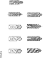
- Fig. 7 shows different possibilities for performing the driver function of the valve piston for the pressure regulator according to the invention according to one embodiment.
- Fig. 8 shows the pressure regulator 800 according to the invention with a heating system to avoid icing or excessive cooling of the pressure regulator in the case of gases with a negative Joule-Thomson coefficient in the working range of the pressure regulator, the heating being generated by means of an electric heater 801.
- Fig. 8.1 shows the pressure regulator 810 according to the invention with a heating system to avoid icing or excessive cooling of the pressure regulator in the case of gases with a negative Joule-Thomson coefficient in the working range of the pressure regulator, the heating being generated by supplying cooling water, the cooler 811 in a suitable manner is attached to the housing 812.
- Fig. 8.2 shows the pressure regulator 820 according to the invention with a heating system to avoid icing or excessive cooling of the pressure regulator in the case of gases with a negative Joule-Thomson coefficient in the operating range of the pressure regulator, the heating being generated by supplying cooling water through cooling channels 821 in the housing 822 of the pressure regulator.
- Fig. 9 shows a control unit 900, consisting at least of the pressure regulator 901 according to the invention, a low pressure sensor 902 and optionally a high pressure sensor 903 in a common housing 904, with a corresponding heating system if required Fig. 8 Fig. 8.1 or Fig. 8.2 can be executed.
- Fig. 9.1 shows a control unit 910, consisting at least of the pressure regulator 911 according to the invention, a low-pressure sensor 912, a low-pressure safety device 913 and optionally a high-pressure sensor 914 in a common housing 915, with a corresponding heating system if required Fig. 8 , Fig. 8.1 or Fig. 8.2 can be executed.
- a spring-loaded closing body or a bursting disc can be installed as a low-pressure safety device.
- the high-pressure storage container can be filled via the control unit with suitably designed line connections.
- a check valve for filling the high-pressure storage container can be integrated into the control unit via the control unit and corresponding line connections.
- a filter element can be integrated into the control unit.
- the filling coupling for filling the high-pressure storage container can be integrated into the control unit via the control unit and corresponding line connections.
- a system shut-off valve can be integrated into the control unit on the high-pressure side or on the low-pressure side.
- a temperature-dependent safety device can be installed in the control unit.
- control unit can be integrated into the cylinder valve.
- control unit in a further embodiment, individual elements of the control unit can be accommodated in separate housings.
- the electronic control device can be attached directly to the control unit or to the pressure regulator.
- the electromechanical locking unit is considered to be a locking unit based on the functional principle of electro-magneto-mechanical energy conversion.
- a locking unit based on the functional principle of electro-hydraulic-mechanical energy conversion, electropneumatic-mechanical energy conversion, electro-mechanical energy conversion (electric motor) or a coupling of any energy conversion principles is used.
- the pressure regulator (107, 200, 300, 400, 500, 600, 800, 810, 820, 901, 911) has several flow paths (206a, 206b, 306, 306a, 406, 406a) of different cross-sections between the inlet-side high-pressure chamber (203, 303, 403, 501) and the low-pressure chamber (205, 305, 405, 502) on the outlet side
- a control opens or closes the flow paths (206b, 306a, 406a) with a small cross-section and at low pressures at high pressures or at low volume flows the flow paths (206b, 306a, 406a) with a large cross-section indirectly.
- the pressure regulator (107, 200, 300, 400, 500, 600, 800, 810, 820, 901, 911) has several flow paths of the same cross section between the inlet-side high-pressure chamber (203, 303, 403, 501) and the outlet-side low-pressure chamber (205, 305, 405, 502), a control opens or closes a few flow paths at high pressures or low volume flows and several flow paths indirectly at low pressures.
- the control opens flow paths indirectly when the working pressure is not reached and opens flow paths indirectly when the working pressure is exceeded.
Landscapes
- Physics & Mathematics (AREA)
- Fluid Mechanics (AREA)
- Engineering & Computer Science (AREA)
- General Physics & Mathematics (AREA)
- Automation & Control Theory (AREA)
- General Engineering & Computer Science (AREA)
- Combustion & Propulsion (AREA)
- Mechanical Engineering (AREA)
- Chemical & Material Sciences (AREA)
- Magnetically Actuated Valves (AREA)
- Control Of Fluid Pressure (AREA)
- Valve Housings (AREA)
- Output Control And Ontrol Of Special Type Engine (AREA)
- Fuel-Injection Apparatus (AREA)
- Fuel Cell (AREA)
- Cooling, Air Intake And Gas Exhaust, And Fuel Tank Arrangements In Propulsion Units (AREA)
- Feeding And Controlling Fuel (AREA)
Description
- Die vorliegende Erfindung betrifft eine Kraftstoffversorgungsanlage und einen Druckregler für eine Kraftstoffversorgungsanlage zum Zuführen eines Kraftstoffes von einem Speicher zu einem Verbraucher, und ein Verfahren zur Druckregelung.
- Alternative gasförmige Energieträger wie Erdgas, Methan, Biogas und Wasserstoff gewinnen im Verkehrswesen aufgrund ihres CO2-Einspapotentials und aus Gründen der Versorgungssicherheit zunehmend an Bedeutung. Diese Energieträger werden zur Erzielung der geforderten Reichweiten typischerweise in komprimierter Form in Druckzylindern bei Nenndrücken von bis zu 700 bar gespeichert und dem Verbraucher bei einem Arbeitsdruck von ca. 10 bar zur Verfügung gestellt.
- Der Druckregler hat die Aufgabe, das gespeicherte Gas vom Speicherdruck auf einen vorgegebenen, meist von den Betriebsbedingungen des Fahrzeuges abhängigen Arbeitsruck zu reduzieren und ist somit ein wesentliches Element eines Kraftstoffversorgungssystems.
- Dem Fachmann sind unterschiedliche Ausführungsformen für Druckregler bekannt:
AusUS 7 159 611 ist ein mechanischer Einstufen-Druckregler nach dem Stand der Technik bekannt: Mit einer mechanischen Druckreduziereinheit wird der Speicherdruck auf den Arbeitsdruck herabgesetzt, wobei der Arbeitsdruck durch die einstufige mechanische Bauart in weiten Grenzen schwankt und im Betrieb unveränderbar eingestellt ist. - Aus
DE 600 21 694 ist ein mechanischen Zweistufen-Druckregler nach dem Stand der Technik bekannt: Mit zwei mechanischen und hintereinander angeordneten Druckreduziereinheiten wird der Speicherdruck auf den Arbeitsdruck herabgesetzt, wobei der Arbeitsdruck durch die zweistufige mechanische Bauart im Betrieb unveränderbar eingestellt ist und der Druckregler ausladend baut. - Aus
DE 102 04 746 ist ein elektromechanischer Einstufen-Druckregler nach dem Stand der Technik bekannt: Mit einer, von einer Magnetspule unterstützten, einstufigen mechanischen Druckreduziereinheit wird der Speicherdruck auf den Arbeitsdruck herabgesetzt, wobei der Arbeitsdruck durch die einstufige kombinierte Bauart im Betrieb nur innerhalb eines durch die Magnetkraft festgelegten engen Bereich verstellt werden kann. - Aus
DE 10 2008 034 581 ist ein elektromechanischer Zweistufen-Druckregler nach dem Stand der Technik bekannt: Mit einer mechanischen Druckreduziereinheit und einem nachfolgendem elektronischen Proportionalventil wird der Speicherdruck auf den Arbeitsdruck herabgesetzt, wobei durch die zweistufige kombinierte Bauart ein ausladender und komplexer Bauteil entsteht. -
DE 29 37 978 A1 offenbart einen Gasdruckregler mit einem Druckmesser, der in Abhängigkeit von dem Verhältnis von Soll- zu Istwert des Gasraumdrucks Magnetventile zu den Druckausgleichsauslässen steuert. -
JP 2001/066020 A -
DE 10 2007 039 925 A1 offenbart einen Druckregler, wobei mehrere Ventilstufen verwendet werden, um geringe Durchflüsse zu bedienen und um ein Dämpfungsverhältnis des Reglers zu maximieren. -
US 5,048,790 zeigt ein selbst modulierendes Regelventil. Bei dem Regelventil wird eine Scheibenanordnung durch verschiedene Druckkammern angehoben um das Ventil zu öffnen. -
US 2005/0217734 A1 zeigt ein elektromagnetisches Ventil. Das elektromagnetische Ventil verbindet ein Kraftstofftank mit einem Kanister. Wenn eine Spule betätigt wird, dann wird ein erster Ventilkörper 50 angehoben und eine Fluidpassage zwischen Kraftstofftank und Kanister geöffnet. Sobald eine Druckdifferenz zwischen dem Tank und dem Kanister abfällt, fällt auch die Anziehungskraft eines zweiten Ventilkörper in Richtung eines zweiten Ventilsitzes ab. Durch eine Feder wird dann der zweite Ventilkörper in Richtung des ersten Ventilkörpers 50 gedrückt, wodurch eine größere Öffnung freigegeben wird. Bei den unterschiedlichen Druckreglern nach dem Stand der Technik ist ein Strömungsweg zwischen dem eingangsseitigen Hochdruckraum und dem ausgangsseitigen Niederdruckraum ausgeführt, wobei bei einstufigen Druckreglern eine Verschlusseinheit und bei zwei- bzw. mehrstufigen Druckreglern zwei- bzw. mehrerer hintereinander angeordnete Verschlusseinheiten in dem einen Strömungsweg zwischen dem eingangsseitigen Hochdruckraum und dem ausgangsseitigen Niederdruckraum ausgeführt sind und den Strömungsweg in geeigneter Weise öffnen und verschließen. - Die Erfindung vermeidet die Nachteile des Standes der Technik und schafft einen Druckregler für beliebige Eingangsdrücke in kompakter und einfacher Bauweise, der bei geringem Leistungsbedarf im Betrieb mit hoher Regelgenauigkeit einen in weiten Grenzen entsprechend einem Steuersignal variablen Ausgangsdruck bereitstellt und folgende Vorteile aufweist:
- kompakte Bauform durch gewähltes Funktionsprinzip
- hohe Anpassungsfähigkeit durch elektronischer Ansteuerung
- hohe innere Dichtheit durch große Druckfläche und Rückstellfeder
- Entfall eines Systemabsperrventils durch hohe innere Dichtheit
- stromlos geschlossen durch den Behälterdruck
- hohe Ausfallssicherheit durch robustes Design und geringe Bauteilanzahl
- niedrige Herstellungskosten durch geringe Bauteilanzahl
- hohe Variabilität durch einfache Anpassung für unterschiedliche Gase.
- Erfindungsgemäß wird dies dadurch erreicht, dass zwischen einem einlassseitigem Hochdruckraum und einem auslassseitigem Niederdruckraum zumindest zwei Strömungswege mit bestimmtem Querschnitt ausgeführt sind und mit einer auf der Hoch- oder auf der Niederdruckseite angeordneten Verschlusseinheit geöffnet oder verschlossen werden, wobei zwischen zwei Betriebweisen unterschieden wird:
- Hochdruckbereich: Bei hohen Drücken im eingangsseitigen Hochdruckraum oder bei kleinen Volumenströmen wird der Strömungsweg mit dem kleineren Querschnitt durch die Verschlusseinheit freigegeben, wobei aufgrund der Flächenverhältnisse eine kleine elektrische Leistung benötigt wird.
- Niederdruckbereich: Bei niedrigen Drücken im eingangsseitigen Hochdruckraum wird der Strömungsweg mit dem größeren Querschnitt durch die Verschlusseinheit freigegeben, wobei aufgrund der Druckverhältnisse nur eine kleine elektrische Leistung benötigt wird.
- Der Übergang zwischen den beiden Betriebsweisen wird durch den Querschnitt der Strömungswege und durch die Betätigungskraft der Verschlusseinheit festgelegt. Die Strömungswege können nebeneinander angeordnet sein.
- Anhand der Zeichnungen werden verschiedene Ausführungsformen der Erfindung im Folgenden erläutert:
-
Fig. 1 zeigt schematisch eine Kraftstoffversorgungsanlage eines gasbetriebenen Kraftfahrzeuges -
Fig. 2 zeigt einen Druckregler im nicht erregten geschlossenen Zustand -
Fig. 2.1 zeigt einen Druckregler im erregten geöffneten Zustand bei hohen Drücken im eingangsseitigen Hochdruckraum (Hochdruckbereich) -
Fig. 2.2 zeigt einen Druckregler im erregten geöffneten Zustand bei niedrigen Drücken im eingangsseitigen Hochdruckraum (Niederdruckbereich) -
Fig. 3 zeigt einen Druckregler gemäß einem Ausführungsbeispiel der vorliegenden Erfindung im nicht erregten geschlossenen Zustand -
Fig. 3.1 zeigt einen Druckregler gemäß einem Ausführungsbeispiel der vorliegenden Erfindung im erregten geöffneten Zustand bei hohen Drücken im eingangsseitigen Hochdruckraum (Hochdruckbereich) -
Fig. 3.2 zeigt einen Druckregler gemäß einem Ausführungsbeispiel der vorliegenden Erfindung im erregten geöffneten Zustand bei niedrigen Drücken im eingangsseitigen Hochdruckraum (Niederdruckbereich) -
Fig. 4 zeigt einen Druckregler gemäß einem Ausführungsbeispiel der vorliegenden Erfindung im nicht erregten geschlossenen Zustand -
Fig. 4.1 zeigt einen Druckregler gemäß einem Ausführungsbeispiel der vorliegenden Erfindung im erregten geöffneten Zustand bei hohen Drücken im eingangsseitigen Hochdruckraum (Hochdruckbereich) -
Fig. 4.2 zeigt einen Druckregler gemäß einem Ausführungsbeispiel der vorliegenden Erfindung im erregten geöffneten Zustand bei niedrigen Drücken im eingangsseitigen Hochdruckraum (Niederdruckbereich) -
Fig. 5 zeigt einen Druckregler gemäß einem Ausführungsbeispiel der vorliegenden Erfindung im nicht erregten geschlossenen Zustand mit geänderter Abdichtung des Schließkörpers. -
Fig. 6 zeigt einen Druckregler gemäß einem Ausführungsbeispiel der vorliegenden Erfindung im nicht erregten geschlossenen Zustand mit geändertem Ventilkolben. -
Fig. 7 zeigt unterschiedliche Ausführungen für die Mitnehmerfunktion des Ventilkolbens für den erfindungsgemäßen Druckregler gemäß einer Ausführungsform -
Fig. 8 zeigt einen Druckregler gemäß der vorliegenden Erfindung mit einem Ausführungsbeispiel für einen ausgeführten Wämeübertrager. -
Fig. 8.1 zeigt einen Druckregler gemäß der vorliegenden Erfindung mit einem Ausführungsbeispiel für einen ausgeführten Wämeübertrager. -
Fig. 8.2 zeigt einen Druckregler gemäß der vorliegenden Erfindung mit einem Ausführungsbeispiel für einen ausgeführten Wämeübertrager. -
Fig. 9 zeigt ein Ausführungsbeispiel einer Regeleinheit mit dem erfindungsgemäßen Druckregler. -
Fig. 9.1 zeigt ein Ausführungsbeispiel einer Regeleinheit mit dem erfindungsgemäßen Druckregler. - Wie in
Fig. 1 gezeigt, umfasst eine Kraftstoffversorgungsanlage 100 , insbesondere eines gasbetriebenen Kraftfahrzeuges, für die Versorgung eines Verbrauchers 101, mit gasförmigen Krafftstoff wie Erdgas, Methan, Biogas, Wasserstoff oder dergleichen aus einem oder mehreren Speicherbehältern 102 samt Tankventil 103, die bei der Betankung über eine befüllseitig angeordnete Befüllkupplung 104 mit integrierter Rückflusssperre und einer daran anschließenden Gaszuführleitung 105 mit Kraftstoffgas versorgt werden. Für die Entnahme ist weiters eine Regeleinheit 106, zumindest bestehend aus Druckregler 107, Hochdrucksensor 108, Niederdrucksensor 109 und Sicherheitseinrichtungen 110 (Hochdrucksicherung, Niederdrucksicherung, Thermische Sicherung) vorgesehen, die von einem Steuergerät 111, dass das Steuersignal nach Vorgabe des Verbrauchers 101 und unter Berücksichtigung des Speicherdruckes und des Arbeitsdruckes erzeugt, angesteuert wird. - In einer weiteren Ausführungsform kann die Betankung, ausgehend von der befüllseitig angeordneten Befüllkupplung mit integrierter Rückflusssperre über die Regeleinheit erfolgen, wobei eingangsseitig wahlweise ein Rückschlagventil und wahlweise ein Filter sowie geeignete Leitungsanschlüsse zur Befüllkupplung und zu den Hochdruck-Speicherbehältern angeordnet sind.
- In einer weiteren Ausführungsform kann die Befüllkupplung mit integrierter Rückflusssperre in die Regeleinheit integriert werden.
- In einer weiteren Ausführungsform kann ein Systemabsperrventil in die Regeleinheit integriert werden.
- In einer weiteren Ausführungsform kann der Druckregler in das Flaschenventil integriert werden.
- In einer weiteren Ausführungsform kann die Regeleinheit in das Flaschenventil integriert werden.
- Wie in
Fig. 2 gezeigt, umfasst der Druckreger 200 ein Gehäuse 201, in welchem zumindest ein Einlass 202 mit nachfolgendem Hochdruckraum 203, ein Auslass 204 mit vorgelagertem Niederdruckraum 205, Strömungswege 206a und 206b zwischen dem Hochdruckraum 203 und dem Niederdruckraum 205, Dichtsitze 207a und 207b im Strömungsweg 206a und 206b zwischen dem Hochdruckraum 203 und dem Niederdruckraum 205, Verschlusseinheiten 209a und 209b mit einem inneren Gewinde 210a und 210b für die Verschraubung der Verschlusseinheiten 209a und 209b im Gehäuse 201 und Dichtsitze 211a und 211b für die Abdichtung der Verschlusseinheiten 209a und 209b im Gehäuse 201 vorgesehen sind. Die Verschlusseinheit 209a und 209b umfasst ein Ventilgehäuse 212a und 212b mit einem Einschraubteil 213a und 213b und gegenüberlegend einem Führungsteil 214a und 214b. Der Einschraubteil 213a und 213b ist mit einem äußeren Gewinde 215a und 215b zur Verschraubung mit dem inneren Gewinde 210a und 210b des Gehäuses 201, einer außenliegenden Nut 216a und 216b für die Aufnahmebohrungen 208a und 208b zur Aufnahme eines Dichtringes 217a und 217b zur Abdichtung des Ventilgehäuses 212a und 212b gegenüber dem Gehäuse 201 und einer Werkzeugaufnahme 218a und 218b zum Erfassen durch ein Werkzeug zum Einschrauben der Verschlusseinheiten 209a und 209b in das Gehäuse 201 versehen. Der Führungsteil 214a und 214b ist mit einer außenliegenden Ringnut 219a und 219b zur Aufnahme eines Sicherungsringes 220a und 220b zur Fixierung der auf den Führungsteil 214a und 214b aufgesetzten Magnetspule 221a und 221b versehen. Im Inneren des Ventilgehäuses 212a und 212b ist ein Ventilkolben 222a und 222b bestehend aus einem Anker 223a und 223b, einem Mitnehmer 224a und 224b, einer Feder 225a und 225b und einem Schließkörper 226a und 226b, verschiebbar zwischen einer Schließstellung und einer Offenstellung angeordnet. Am ersten Ende des magnetischen Anker 222a und 222b wird der Schließkörper 226a und 226b aufgenommen, wobei eine innenliegende Nut 227a und 227b zur Aufnahme des Mitnehmers 224a und 224b für den Schließkörper 226a und 226b vorgesehen ist. Am gegenüberliegenden zweiten Ende wird der Anker 222a und 222b im Führungsteil 214a und 214b mit geringem Radialspiel geführt, wobei am zweiten Ende eine Bohrung 228a und 228b zur Aufnahme der Feder 224a und 224b vorgesehen ist. Am Schließkörper 226a und 226b aus einem Dichtwerkstoff ist eine Dichtfläche 229a und 229b und eine außenliegende Nut 230a und 230b zur Abstützung des Mitnehmers 223a und 223b ausgeführt. - In einer weiteren Ausführungsform kann der Schließkörper 226a und 226b direkt im magnetischen Anker 222a und 222b ohne Mitnehmers 223a und 223b befestigt werden, wobei wahlweise eine Entlüftung der rückseitigen Fläche des Mitnehmers 223a und 223b vorzusehen ist.
- In einer weiteren Ausführungsform kann der Schließkörper 226a und 226b mit einer Nut zur Aufnahme einer geeigneten Dichtung ausgeführt werden, wobei wahlweise eine Entlüftung der rückseitigen Nutfläche vorzusehen ist.
- In einer weiteren Ausführungsform kann das Gehäuse 201 mit einer Nut zur Aufnahme einer geeigneten Dichtung ausgeführt werden, wobei wahlweise eine Entlüftung der rückseitigen Nutfläche vorzusehen ist.
- In einer weiteren Ausführungsform kann die Dichtfläche nicht direkt im Gehäuse, sondern an einem geeigneten Einschraubteil oder an einem geeigneten Einpressteil ausgeführt werden.
- In einer weiteren Ausführungsform kann anstatt einem Schließkörper aus einem geeigneten Dichtmaterial ein metallischer Schließkörper verwendet werden.
- In einer weiteren Ausführungsform können die Verschlusseinheiten 209a und 209b auf der Niederdruckseite angeordnet werden.
- In einer weiteren Ausführungsform können die Verschlusseinheiten 209a und 209b an beliebiger Stelle des Gehäuses angeordnet werden.
- In einer weiteren Ausführungsform können die Verschlusseinheiten 209a und 209b an beliebiger Stelle des Gehäuses angeordnet werden.
- Nachfolgend wird die Wirkungsweise eines Druckreglers beschrieben:
Wie inFig. 2 gezeigt, drückt im stromlosen und nicht erregtem Zustand der Magnetspule 221a die Feder 225a und 225b den Anker 223a und 223b des Ventilkolbens 222a und 222b nach unten, wobei sich die Dichtfläche 229a und 229b des Schließkörpers 226a und 226b am Dichtsitz 207a und 207b im Gehäuse 201 abstützt und somit die Strömungswege 206a und 206b zwischen dem Hochdruckraum 203 und dem Niederdruckraum 205 verschließt. - Wie in
Fig. 2.1 gezeigt, wird durch Ansteuerung und Erregung der Magnetspule 221b der Anker 223b des Ventilkolbens 222b entgegen der wirksamen Feder 225b angehoben und hebt die Dichtfläche 229b des Schließkörpers 226b durch den Mitnehmer 224b vom Dichtsitz 207b im Gehäuse 201 ab, wobei der Strömungsweg 206b vom Hochdruckraum 203 zum Niederdruckraum 205 frei liegt. Der Betriebszustand nach Fig. 21 wird bei hohen Eingangsdrücken umgesetzt, wobei aufgrund der geringen Größe der nicht druckausgeglichenen Fläche eine geringe elektrische Leistung zum Anheben des Ventilkolbens benötigt und aufgrund des kleinen freigegebenen Strömungsdurchmessers eine große Druckreduktion erreicht. - Wie in
Fig. 2.2 gezeigt, wird durch Ansteuerung und Erregung der Magnetspule 221a der Anker 223a des Ventilkolbens 222a entgegen der wirksamen Feder 225a angehoben und hebt die Dichtfläche 229a des Schließkörpers 226a durch den Mitnehmer 224a vom Dichtsitz 207a im Gehäuse 201 ab, wobei der zweite Strömungsweg 206a vom Hochdruckraum 203 zum Niederdruckraum 205 frei liegt. Der Betriebszustand nach Fig. 22 wird bei mittleren und niedrigen Eingangsdrücken umsetzt und aufgrund des großen Strömungsquerschnittes ein großer Massenstrom bei kleiner Druckreduktion erreicht. - Wie in
Fig. 3 gezeigt, umfasst der Druckreger 300 ein Gehäuse 301, in welchem zumindest ein Einlass 302 mit einem nachfolgenden Hochdruckraum 303, ein Auslass 304 mit einem vorgelagertem Niederdruckraum 305, ein Strömungsweg 306 zwischen dem Einlass 302 und dem Auslass 304, ein Dichtsitz 307 im Strömungsweg 306 zwischen dem Hochdruckraum 303 und dem Niederdruckraum 305, eine Aufnahmebohrung 308 für die Aufnahme der Verschlusseinheit 309 mit einem inneren Gewinde 310 für die Verschraubung der Verschlusseinheit 309 im Gehäuse 301 und ein Dichtsitz 311 für die Abdichtung der Verschlusseinheit 309 im Gehäuse 301 vorgesehen sind. Die Verschlusseinheit 309 umfasst ein Ventilgehäuse 312 mit einem Einschraubteil 313 und gegenüberlegend einem Führungsteil 314. Der Einschraubteil 313 ist mit einem äußeren Gewinde 315 zur Verschraubung mit dem inneren Gewinde 310 des Gehäuses 301, einer außenliegenden Nut 316 für die Aufnahme eines Dichtringes 317 zur Abdichtung der Verschlusseinheit 309 gegenüber dem Gehäuse 301 und einer Werkzeugaufnahme 318 zum Erfassen durch ein Werkzeug zum Einschrauben der Verschlusseinheit 309 in das Gehäuse 301 versehen. Der Führungsteil 314 ist mit einer außenliegenden Ringnut 319 zur Aufnahme eines Sicherungsringes 320 zur Fixierung der auf den Führungsteil 314 aufgesetzten Magnetspule 321 versehen. Im Inneren der Verschlusseinheit 309 ist ein Ventilkolben 322, bestehend aus einem Anker 323, einem Mitnehmer 324, einer Feder 325 und einem Schließkörper 326, verschiebbar zwischen einer Schließstellung einer ersten Offenstellung und einer zweiten Offenstellung angeordnet. Am ersten Ende des magnetischen Anker 323 wird der Schließkörper 326 aufgenommen, wobei ein innenliegender Dichtsitz 327 zur Abstützung an der oberen Dichtfläche 328 des Schließköpers 326, eine innenliegende Nut 329 zur Aufnahme des Mitnehmers 324, und zumindest eine Querbohrung 330 vorgesehen ist. Am gegenüberliegenden zweiten Ende wird der Anker 323 im Führungsteil 314 mit geringem Radialspiel geführt, wobei das offene Ende 331 zur Aufnahme der Feder 325 vorgesehen ist. Am Schließkörper 326 aus einem Dichtwerkstoff ist eine obere Dichtfläche 328, gegenüberliegend eine unteren Dichtfläche 332 mit unterschiedlicher Abmessung, eine axiale Drosselbohrung 333 zwischen den beiden Dichtflächen und einer außenliegende Nut 334 zur Abstützung des Mitnehmers 324 der Verschlusseinheit 309 ausgeführt. - Nachfolgend wird die Wirkungsweise des erfindungsgemäßen elektromechanischen Druckreglers beschrieben:
Wie inFig. 3 gezeigt, drückt im stromlosen und nicht erregtem Zustand der Magnetspule 321 die Feder 325 den Anker 323 der Verschlusseinheit 309 nach unten, wobei sich die untere Dichtfläche 332 des Schließkörpers 326 am Dichtsitz 307 im Gehäuse 301 und die obere Dichtfläche 328 des Schließkörpers 326 an der Dichtfläche 327 des Ankers 323 abstützt und somit den Strömungsweg 306 zwischen dem Hochdruckraum 303 und dem Niederdruckraum 305 verschließt. In diesem Betriebszustand ist zwischen dem Mitnehmer 324 und dem Schließkörper 326 in Bewegungsrichtung des Ventilkolbens 322 ein Spalt 335 vorhanden. - Wie in
Fig. 3.1 gezeigt, wird durch Ansteuerung und Erregung der Magnetspule 321 der Anker 323 des Ventilkolbens 322 entgegen der wirksamen Feder 325 angehoben, wobei sich die untere Dichtfläche 332 des Schließkörpers 326 am Dichtsitz 307 im Gehäuse 301 abstützt und die Dichtfläche 327 des Ankers 323 von der oberen Dichtfläche 329 des Schließkörpers 326 abgehoben wird, wodurch ein Strömungsweg 306a vom Hochdruckraum 303 über die Querbohrung 330 im Anker 323 und der Drosselbohrung 333 im Schließkörper 326 zum Niederdruckraum 305 frei liegt. In diesem Betriebszustand ist zwischen dem Mitnehmer 324 und dem Schließkörper 326 in Bewegungsrichtung des Ventilkolbens 322 ein Spalt 335 vorhanden. Der Betriebszustand nachFig. 3.1 wird bei hohen Eingangsdrücken umgesetzt, wobei aufgrund der geringen Größe der nicht druckausgeglichenen Fläche eine geringe elektrische Leistung zum Anheben des Ventilkolbens benötigt und aufgrund des kleinen freigegebenen Strömungsdurchmessers eine große Druckreduktion erreicht. - Wie in
Fig. 3.2 gezeigt, wird durch Erhöhung der Erregung der Magnetspule 321 der Anker 323 des Ventilkolbens 322 weiter entgegen der wirksamen Feder 325 angehoben, der Spalt 335 zwischen dem Mitnehmer 324 und dem Schließkörper 326 in Bewegungsrichtung des Ventilkolbens 322 geschlossen und der Schließkörper 326 vom Mitnehmer 324 angehoben, wobei die untere Dichtfläche 332 des Schließkörpers 326 vom Dichtsitz 307 im Gehäuse 301 abgehoben und bei geöffnetem Strömungsweg 306a der Strömungsweg 306 zwischen dem Hochdruckraum 303 über den Dichtsitz 307 im Gehäuse 301 zum Niederdruckraum 305 frei liegt. Der Betriebszustand nachFig. 3.2 wird bei mittleren und niedrigen Eingangsdrücken umsetzt und aufgrund des großen Strömungsquerschnittes ein großer Massenstrom bei kleiner Druckreduktion erreicht. - Wie in
Fig. 4 gezeigt, umfasst der Druckreger 400 ein Gehäuse 401, in welchem zumindest ein Einlass 402 mit einem nachfolgenden Hochdruckraum 403, ein Auslass 404 mit einem vorgelagertem Niederdruckraum 405, ein Strömungsweg 406 zwischen dem Einlass 402 und dem Auslass 404, ein Dichtsitz 407 im Strömungsweg 406 zwischen dem Hochdruckraum 403 und dem Niederdruckraum 405, eine Aufnahmebohrung 408 für die Aufnahme des Schließkörpers 409 im Gehäuse 401 samt Nut 410 für die Aufnahme eines Sicherungsringes 411 zur Abstützung eines Gegenhalters 412 für die erste Feder 413, eine Aufnahmebohrung 414 für die Aufnahme der Verschlusseinheit 415 mit einem inneren Gewinde 416 für die Verschraubung der Verschlusseinheit 415 im Gehäuse 401 und ein Dichtsitz 417 für die Abdichtung der Verschlusseinheit 415 im Gehäuse 401 vorgesehen sind. Die Verschlusseinheit 415 umfasst ein Ventilgehäuse 418 mit einem Einschraubteil 419 und gegenüberlegend einem Führungsteil 420. Der Einschraubteil 419 ist mit einem äußeren Gewinde 421 zur Verschraubung mit dem inneren Gewinde 416 des Gehäuses 401, einer außenliegenden Nut 422 für die Aufnahme eines Dichtringes 423 zur Abdichtung der Verschlusseinheit 415 gegenüber dem Gehäuse 401 und einer Werkzeugaufnahme 424 zum Erfassen durch ein Werkzeug zum Einschrauben der Verschlusseinheit 415 in das Gehäuse 401 versehen. Der Führungsteil 420 ist mit einer außenliegenden Ringnut 425 zur Aufnahme eines Sicherungsringes 426 zur Fixierung der auf den Führungsteil 420 aufgesetzten Umkehrhubmagnetspule 427 versehen. Im Inneren der Verschlusseinheit 415 ist ein magnetischer Anker 428 und einer zweiten Feder 429 geringerer Stärke als die erste Feder 413, verschiebbar zwischen einer Schließstellung einer ersten Offenstellung und einer zweiten Offenstellung angeordnet. Am ersten Ende des magnetischen Ankers 428 ist ein außenliegender Dichtsitz 430 zur Abdichtung an der ersten Dichtfläche 431 am Schließkörper 409 ausgeführt. Am gegenüberliegenden zweiten Ende wird der Anker 428 im Führungsteil 420 mit geringem Radialspiel geführt, wobei das offene Ende 432 zur Aufnahme der Feder 429 vorgesehen ist. Am Schließkörper 409 aus einem Dichtwerkstoff ist eine erste Dichtfläche 431, eine zweite Dichtfläche 433 mit unterschiedlicher Abmessung, eine axiale Drosselbohrung 434 zwischen den beiden Dichtflächen und einer Bohrung 435 zur Aufnahme der Feder 413 und wahlweise außen- oder innenliegende Strömungskanäle 436 ausgeführt. - In einer weiteren Ausführungsform kann der Schließkörper 409 mit Nuten zur Aufnahme geeigneter Dichtungen ausgeführt werden, wobei wahlweise eine Entlüftung der rückseitigen Nutflächen vorzusehen ist.
- In einer weiteren Ausführungsform kann das Gehäuse 401 mit Nut zur Aufnahme geeigneter Dichtung ausgeführt werden, wobei wahlweise eine Entlüftung der rückseitigen Nutfläche vorzusehen ist.
- In einer weiteren Ausführungsform kann die Dichtfläche nicht direkt im Gehäuse, sondern an einem geeigneten Einschraubteil oder an einem geeigneten Einpressteil ausgeführt werden.
- In einer weiteren Ausführungsform kann anstatt einem Schließkörper aus einem geeigneten Dichtmaterial ein metallischer Schließkörper verwendet werden.
- Nachfolgend wird die Wirkungsweise des erfindungsgemäßen elektromechanischen Druckreglers beschrieben:
Wie inFig. 4 gezeigt, drückt im stromlosen und nicht erregtem Zustand der Umkehrhubmagnetspule 427 die Feder 429 den Anker 428 der Verschlusseinheit 415 gegen den Schließkörper 409, wobei sich die erste Dichtfläche 431 des Schließkörpers 409 an der Dichtfläche 430 des Ankers 428 und die zweite Dichtfläche 433 des Schließkörpers 409 durch die Kraft der Feder 413 am Dichtsitz 407 im Gehäuse 401 abstützt und somit den Strömungsweg 406 zwischen dem Hochdruckraum 403 und dem Niederdruckraum 405 verschließt. - Wie in
Fig. 4.1 gezeigt, wird durch Ansteuerung und Erregung der Umkehrhubmagnetspule 427 der Anker 428 entgegen der wirksamen Feder 433 bewegt, wobei sich die zweite Dichtfläche 433 des Schließkörpers 409 durch die Kraft der Feder 413 am Dichtsitz 407 im Gehäuse 401 abstützt und die Dichtfläche 430 des Ankers 428 von der ersten Dichtfläche 431 des Schließkörpers 409 abgehoben wird, wodurch der Strömungsweg 406a vom Hochdruckraum 403 über die Drosselbohrung 434 im Schließkörper 409 zum Niederdruckraum 405 frei liegt. Der Betriebszustand nachFig. 4.1 wird bei hohen Eingangsdrücken umgesetzt, wobei aufgrund der geringen Größe der nicht druckausgeglichenen Fläche eine geringe elektrische Leistung zum Anheben des Ankers benötigt und aufgrund des kleinen freigegebenen Strömungsdurchmessers eine große Druckreduktion erreicht wird. - Wie in
Fig. 4.2 gezeigt, wird durch Ansteuerung und Erregung der Umkehrhubmagnetspule 427 der Anker 428 entgegen der wirksamen Feder 413 bewegt, wobei sich die Dichtfläche 430 des Ankers 428 an der erste Dichtfläche 431 des Schließkörpers 409 abstützt und die zweite Dichtfläche 433 des Schließkörpers 409 vom Dichtsitz 407 im Gehäuse 401 abgehoben wird, wodurch der Strömungsweg 406 vom Hochdruckraum 403 über den Dichtsitz 407 im Gehäuse zum Niederdruckraum 405 frei liegt. Der Betriebszustand nachFig. 4.2 wird bei mittleren und niedrigen Eingangsdrücken umsetzt und aufgrund des großen Strömungsquerschnittes ein großer Massenstrom bei kleiner Druckreduktion erreicht. -
Fig. 5 zeigt den erfindungsgemäßen Druckregler 500 mit einem geänderten Abdichtsystem zwischen dem Hochdruckraum 501 und dem Niederdruckraum 502, wobei der Schließkörper 503 zumindest eine geeignete Aufnahme 504 für eine geeignete Dichtung 505 aufweist , die sich am Dichtsitz 506 im Gehäuse 507 abstützt und der Anker 508 eine geeignete Aufnahme 509 für eine geeignete Dichtung 510 aufweist, die sich am Schließkörper 503 abstützt, wobei wahlweise eine Entlüftung der rückseitigen Nutflächen vorzusehen ist. - In einer weiteren Ausführungsform weist der Schließkörper zwei Aufnahmen für die beiden Dichtungen auf.
- In einer weiteren Ausführungsform weisen das Gehäuse und der Anker jeweils eine Aufnahme für die beiden Dichtungen auf.
- In einer weiteren Ausführungsform weist der das Gehäuse zwei Aufnahmen für die beiden Dichtungen auf.
- In einer weiteren Ausführungsform kann zur Stabilisierung des Schließkörpers eine separate Hülse im Schließköper verbaut werden.
- In einer weiteren Ausführungsform kann der Schließköper mehrteilig ausgeführt werden.
- In einer weiteren Ausführungsform kann die Dichtfläche nicht direkt im Gehäuse, sondern an einem geeigneten Einschraubteil oder an einem geeigneten Einpressteil ausgeführt werden.
- In einer weiteren Ausführungsform kann anstatt einem Schließkörper aus einem geeigneten Dichtmaterial ein metallischer Schließkörper verwendet werden.
- Weitere Ausführungsformen des Abdichtsystems zwischen dem Hochdruckraum und dem Niederdruckraum entstehen durch Kombination der bereits beschriebenen Ausführungsformen für das Abdichtungssystem.
-
Fig. 6 zeigt den erfindungsgemäßen Druckregler 600 mit einem geänderten Erregersystem. Der Anker 601 verfügt über ein offenes Ende 602 und ein geschlossenes Ende 603, wobei sich die Feder 604 an einer außenliegenden Schulter 605 des offenen Ankerendes 602 gegenüber einer innenliegenden Schulter 606 des offenen Ventilgehäuses 607 abstützt, sodass durch die konstruktive Gestaltung des Arbeitsluftspaltes 608 der Verlauf der Magnetkraftkennlinie gezielt beeinflusst werden kann. - Grundsätzlich kann eine Verschlusseinheit mit diskreter Schaltfunktion (Zweistellungs-Hubmagnet mit einer Offen- und einer Schließstellung bei Verwendung einer elektromechanischen Verschlusseinheit) oder eine kontinuierlich schaltende Verschlusseinheit (Proportionalmagnet mit beliebigen Zwischenstellungen zwischen der Offen- und der Schließstellung bei Verwendung einer elektromechanischen Verschlusseinheit) zur Lagebeeinflussung des Schließkörpers verwendet werden.
- In einer weiteren Ausführungsform ist das Ventilgehäuse mit einer Einrichtung zum mechanischen Öffnen und wahlweise zum mechanischen Schließen des Schließkörpers versehen.
- In einer weiteren Ausführungsform ist das Ventilgehäuse zur besseren Magnetflussführung mehrteilig ausgeführt.
- In einer weiteren Ausführungsform ist der Anker zur besseren Magnetfußführung oder zur besseren Führung im Ventilgehäuse mehrteilig ausgeführt.
- In einer weiteren Ausführungsform können mehrere Magnetspulen hintereinander verbaut werden.
- Weitere Ausführungsformen entstehen, wenn die strömungstechnisch parallel angeordneten Strömungswege zwischen dem eingangsseitigem Hochdruckraum und dem ausgangsseitigem Niederdruckraum durch einen rotierenden Aktor oder rotierende Aktoren geöffnet oder verschlossen werden.
-
Fig. 7 zeigt unterschiedlich Möglichkeiten zur Ausführung der Mitnehmerfunktion des Ventilkolbens für den erfindungsgemäßen Druckregler nach einer Ausführungsform. -
Fig. 8 zeigt den erfindungsgemäßen Druckregler 800 mit einem Heizsystem zur Vermeidung von Vereisung oder zu starker Abkühlung des Druckreglers bei Gasen mit negativem Joule-Thomson-Koeffizient im Arbeitsbereich des Druckreglers, wobei die Erzeugung der Heizwärme mittels eingesetztem elektrischen Heizer 801 erfolgt. -
Fig. 8.1 zeigt den erfindungsgemäßen Druckregler 810 mit einem Heizsystem zur Vermeidung von Vereisung oder zu starker Abkühlung des Druckreglers bei Gasen mit negativem Joule-Thomson-Koeffizient im Arbeitsbereich des Druckreglers, wobei die Erzeugung der Heizwärme durch Zufuhr von Kühlwasser erfolgt, wobei der Kühler 811 in geeigneter Weise an das Gehäuse 812 angebaut ist. -
Fig. 8.2 zeigt den erfindungsgemäßen Druckregler 820 mit einem Heizsystem zur Vermeidung von Vereisung oder zu starker Abkühlung des Druckreglers bei Gasen mit negativem Joule-Thomson-Koeffizient im Arbeitsbereich des Druckreglers, wobei die Erzeugung der Heizwärme durch Zufuhr von Kühlwasser erfolgt, dass durch Kühlkanäle 821 im Gehäuse 822 des Druckreglers geführt wird. -
Fig. 9 zeigt eine Regeleinheit 900, bestehend zumindest aus dem erfindungsgemäßen Druckregler 901, einem Niederdrucksensor 902 und wahlweise einem Hochdrucksensor 903 in einem gemeinsamen Gehäuse 904, wobei bei Bedarf ein Heizsystem entsprechendFig. 8 Fig. 8.1 oderFig. 8.2 ausgeführt werden kann. -
Fig. 9.1 zeigt eine Regeleinheit 910, bestehend zumindest aus dem erfindungsgemäßen Druckregler 911, einem Niederdrucksensor 912 einer Niederdruck-Sicherungseinrichtung 913 und wahlweise einem Hochdrucksensor 914 in einem gemeinsamen Gehäuse 915, wobei bei Bedarf ein Heizsystem entsprechendFig. 8 ,Fig. 8.1 oderFig. 8.2 ausgeführt werden kann. - Als Niederdrucksicherheitseinrichtung kann ein federbelasteter Schließkörper oder eine Berstscheibe verbaut werden.
- In einer weiteren Ausführungsform kann die Befüllung der Hochdruck-Speicherbehälter über die Regeleinheit mit geeignet ausgeführten Leitungsanschlüssen erfolgen.
- In einer weiteren Ausführungsform kann ein Rückschlagventil zur Befüllung der Hochdruck-Speicherbehälter über die Regeleinheit und entsprechende Leitungsanschlüsse in die Regeleinheit integriert werden.
- In einer weiteren Ausführungsform kann ein Filterelement in die Regeleinheit integriert werden.
- In einer weiteren Ausführungsform kann die Befüllkupplung zur Befüllung der Hochdruck-Speicherbehälter über die Regeleinheit und entsprechende Leitungsanschlüsse in die Regeleinheit integriert werden.
- In einer weiteren Ausführungsform kann ein Systemabsperrventil hochdruckseitig oder niederdruckseitig in die Regeleinheit integriert werden.
- In einer weiteren Ausführungsform kann eine temperaturabhängige Sicherheitseinrichtung in der Regeleinheit verbaut werden.
- In einer weiteren Ausführungsform kann die Regeleinheit in das Flaschenventil integriert werden.
- In einer weiteren Ausführungsform können einzelne Elemente der Regeleinheit in getrennten Gehäusen untergebracht werden.
- In einer weiteren Ausführungsform kann das elektronische Steuergerät direkt an die Regeleinheit oder an den Druckregler angebaut werden.
- Als elektromechanische Verschlusseinheit in der Beschreibung wird eine Verschlusseinheit nach dem Funktionsprinzip der elektro-magneto-mechanischen Energiewandlung angesehen.
- In einer weiteren Ausführungsform wird eine Verschlusseinheit nach dem Funktionsprinzip der elektro-hydraulisch-mechanischen Energiewandlung, der elektropneumatisch-mechanischen Energiewandlung, der elektro-mechanischen Energiewandlung (Elektromotor) oder eine Kopplung beliebiger Energiewandlungsprinzipien verwendet.
- Im Folgenden werden Verfahren zum Betrieb der Druckregler (107, 200, 300, 400, 500, 600, 800, 810, 820, 901, 911) beschrieben.
- Weist der Druckregler (107, 200, 300, 400, 500, 600, 800, 810, 820, 901, 911) mehrere Strömungswegen (206a, 206b, 306, 306a, 406, 406a) unterschiedlichen Querschnitts zwischen dem eingangsseitigen Hochdruckraum (203, 303, 403, 501) und dem ausgangsseitigen Niederdruckraum (205, 305, 405, 502) auf, so öffnet oder schließt eine Steuerung bei hohen Drücken oder bei kleinen Volumenströmen die Strömungswege (206b, 306a, 406a) mit kleinem Querschnitt und bei niedrigen Drücken die Strömungswege (206b, 306a, 406a) mit großem Querschnitt mittelbar.
- Weist der Druckregler (107, 200, 300, 400, 500, 600, 800, 810, 820, 901, 911) mehreren Strömungswegen gleichen Querschnitts zwischen dem eingangsseitigen Hochdruckraum (203, 303, 403, 501) und dem ausgangsseitigen Niederdruckraum (205, 305, 405, 502) auf, so öffnet oder schließt eine Steuerung bei hohen Drücken oder bei kleinen Volumenströmen wenige Strömungswege und bei niedrigen Drücken mehrere Strömungswege mittelbar.
- Die Steuerung öffnet bei Unterschreitung des Arbeitsdruckes Strömungswege mittelbar und schießt bei Überschreitung des Arbeitsdruckes Strömungswege mittelbar.
Claims (11)
- Druckregler (107, 300, 400, 500, 600, 800, 810, 820, 901, 911) für eine Kraftstoffversorgungsanlage (100), umfassend:zumindest zwei Strömungswege (306, 306a, 406, 406a) zwischen einem Hochdruckraum (303, 403, 501) und einem Niederdruckraum (305, 405, 502), wobei der Druckregler weiterhineine elektromagnetische Einrichtung zum Öffnen und Schließen der zumindest zwei Strömungswege (306, 306a, 406, 406a) umfasst, die eine Magnetspule (321,427) sowie eine Verschlusseinheit (309,415) zur Verschraubung in einem Gehäuse (301, 401) mit einem magnetischen Anker (323, 428) aufweist, wobei sich, in einem stromlosen und unerregten Zustand der Magnetspule (321,427),eine Dichtfläche (327, 430) des magnetischen Ankers (323, 428) an einer ersten Dichtfläche (328, 431) eines einstückigen Schließkörpers (326, 409) abstützt und somit einen ersten Strömungsweg (306a, 406a) der zumindest zwei Strömungswege (306, 306a, 406, 406a) verschließt undeine zweite Dichtfläche (332, 433) des einstückigen Schließkörpers (326, 409) an einem Dichtsitz (307, 407) in dem Gehäuse (301, 401) abstützt und somit einen zweiten Strömungsweg (306, 406) der zumindest zwei Strömungswege (306, 306a, 406, 406a) verschließt, wobei die Magnetspule ansteuerbar und erregbar ist, den magnetischen Anker zu bewegen um einen der zumindest zwei Strömungswege freizugegeben und dadurch gekennzeichnet, dass eine Erhöhung der Erregung der Magnetspule zusätzlich einen zweiten der zumindest zwei Strömungswege freigibt.
- Druckregler (107, 300, 400, 500, 600, 800, 810, 820, 901, 911) nach Anspruch 1, dadurch gekennzeichnet, dass die einzelnen Strömungswege der zumindest zwei Strömungswege (306, 306a, 406, 406a) mit unterschiedlichem Querschnitt ausgeführt sind.
- Druckregler (107, 300, 400, 500, 600, 800, 810, 820, 901, 911) nach Anspruch 1, dadurch gekennzeichnet, dass die einzelnen Strömungswege der zumindest zwei Strömungswege (306, 306a, 406, 406a) mit gleichem Querschnitt ausgeführt sind.
- Druckregler (107, 300, 400, 500, 600, 800, 810, 820, 901, 911) nach einem der vorangegangenen Ansprüche, dadurch gekennzeichnet, dass die einzelnen Strömungswege der zumindest zwei Strömungswege (306, 306a, 406, 406a) unabhängig voneinander geöffnet oder verschlossen werden.
- Druckregler (107, 300, 400, 500, 600, 800, 810, 820, 901, 911) nach einem der Ansprüche 1 bis 3, dadurch gekennzeichnet, dass die einzelnen Strömungswege der zumindest zwei Strömungswege (306, 306a, 406, 406a) nicht unabhängig voneinander geöffnet oder verschlossen werden.
- Druckregler (107, 300, 400, 500, 600, 800, 810, 820, 901, 911) nach einem der vorangegangenen Ansprüche, dadurch gekennzeichnet, dass die zumindest zwei Strömungswege (306, 306a, 406, 406a) in einem gemeinsamen Gehäuse (301,401, 507) ausgeführt werden.
- Druckregler (107, 300, 500, 600, 800, 810, 820, 901, 911) nach einem der vorangegangenen Ansprüche, dadurch gekennzeichnet, dass der magnetische Anker (323) der Verschlusseinheit (309) zur Lageänderung des einstückigen Schließkörpers (326) auf einer Hochdruckseite angeordnet ist.
- Druckregler (107, 400) nach einem der Ansprüche 1 bis 6, dadurch gekennzeichnet, dass der magnetische Anker (428) der Verschlusseinheit zur Lageänderung des einstückigen Schließkörpers (409) auf der Niederdruckseite angeordnet ist.
- Druckregler (107, 300, 500, 600, 800, 810, 820, 901, 911) nach einem der vorangegangenen Ansprüche, dadurch gekennzeichnet, dass der einstückige Schließkörper (503) zumindest eine Aufnahme (504) für eine Dichtung (505) aufweist, die sich am Dichtsitz (506) im Gehäuse (507) abstützt und der Anker (508) eine Aufnahme (509) für eine Dichtung (510) aufweist, die sich am einstückigen Schließkörper (503) abstützt.
- Kraftstoffversorgungsanlage (100) für ein Kraftfahrzeug, umfassend einen Druckregler (107, 300, 400, 500, 600, 800, 810, 820, 901, 911) nach einem der Ansprüche 1 bis 9 einer Regeleinheit (106, 900, 910), über den ein Speicherbehälter (102) der Kraftstoffversorgungsanlage (100) entleert wird.
- Verfahren zum Schalten eines Druckreglers (107, 300, 500, 600, 800, 810, 820, 901, 911) nach einem der Ansprüche 1 bis 9, wobei eine Verschlusseinheit kontinuierlich geschaltet wird, mit beliebigen Zwischenstellungen zwischen einer Offen- und einer Schließstellung.
Applications Claiming Priority (2)
| Application Number | Priority Date | Filing Date | Title |
|---|---|---|---|
| DE102010003016.3A DE102010003016B4 (de) | 2010-03-18 | 2010-03-18 | Druckregler zur Zuführung von Kraftstoff und Kraftstoffversorgungssystem mit einer Regeleinheit aus diesen Druckreglern |
| PCT/EP2011/054099 WO2011113922A2 (de) | 2010-03-18 | 2011-03-18 | Druckregler zur zuführung von kraftstoff und kraftstoffversorgungssystem mit einer regeleinheit aus diesen druckreglern |
Publications (2)
| Publication Number | Publication Date |
|---|---|
| EP2548089A2 EP2548089A2 (de) | 2013-01-23 |
| EP2548089B1 true EP2548089B1 (de) | 2021-05-05 |
Family
ID=44511814
Family Applications (1)
| Application Number | Title | Priority Date | Filing Date |
|---|---|---|---|
| EP11708505.0A Active EP2548089B1 (de) | 2010-03-18 | 2011-03-18 | Druckregler zur zuführung von kraftstoff und kraftstoffversorgungssystem mit einer regeleinheit aufweisend diesen druckregler |
Country Status (11)
| Country | Link |
|---|---|
| US (1) | US9880568B2 (de) |
| EP (1) | EP2548089B1 (de) |
| JP (1) | JP6005527B2 (de) |
| KR (1) | KR101880241B1 (de) |
| CN (1) | CN103109247B (de) |
| BR (1) | BR112012023564B1 (de) |
| CA (1) | CA2793038C (de) |
| DE (1) | DE102010003016B4 (de) |
| ES (1) | ES2881901T3 (de) |
| RU (1) | RU2559865C2 (de) |
| WO (1) | WO2011113922A2 (de) |
Families Citing this family (8)
| Publication number | Priority date | Publication date | Assignee | Title |
|---|---|---|---|---|
| DE102011118848B4 (de) * | 2011-11-18 | 2018-10-31 | BO-INNO GmbH | Gasdruckregelvorrichtung und Gehäuse einer Gasdruckregelvorrichtung |
| DE102014218818A1 (de) * | 2014-09-18 | 2016-04-07 | Continental Automotive Gmbh | Druckminderungseinrichtung für eine Vorrichtung zur Kraftstoffversorgung und Vorrichtung zur Kraftstoffversorgung |
| AT14454U3 (de) * | 2015-07-20 | 2018-08-15 | Ventrex Automotive Gmbh | Druckregler |
| AT517645A1 (de) * | 2015-07-20 | 2017-03-15 | Ventrex Automotive Gmbh | Druckregler |
| DE102016105048A1 (de) * | 2016-03-18 | 2017-09-21 | Volkswagen Aktiengesellschaft | Brennkraftmaschine und Verfahren zum Betreiben einer Brennkraftmaschine |
| DE102018113240A1 (de) * | 2018-06-04 | 2019-12-05 | Volkswagen Aktiengesellschaft | Zuführsystem zum Zuführen eines CNG- oder LNG-Kraftstoffes |
| AT17013U1 (de) | 2019-09-05 | 2021-02-15 | Zieger Dipl Ing Andreas | |
| DE102024204006A1 (de) | 2024-04-29 | 2025-10-30 | Robert Bosch Gesellschaft mit beschränkter Haftung | Druckregelvorrichtung für Gasmotor |
Family Cites Families (47)
| Publication number | Priority date | Publication date | Assignee | Title |
|---|---|---|---|---|
| US1228104A (en) * | 1915-08-18 | 1917-05-29 | Chaplin Fulton Mfg Company | Valve. |
| DE2937978C2 (de) * | 1979-09-20 | 1982-04-01 | Battelle-Institut E.V., 6000 Frankfurt | Gasdruckregler |
| GB2129170B (en) * | 1982-10-21 | 1986-09-24 | Secr Defence | Improvements in or relating to pressure controllers |
| JPS6158964A (ja) * | 1984-08-30 | 1986-03-26 | Mitsubishi Heavy Ind Ltd | ガスエンジン |
| US4760694A (en) * | 1986-10-27 | 1988-08-02 | Rockwell International Corporation | Bi-level thruster |
| HUT54227A (en) * | 1989-05-26 | 1991-01-28 | Magyar Szenhidrogenipari | Apparatus for controlling gas utilization |
| JPH0418797U (de) * | 1990-06-08 | 1992-02-17 | ||
| US5048790A (en) * | 1990-07-18 | 1991-09-17 | Target Rock Corporation | Self-modulating control valve for high-pressure fluid flow |
| JPH05126105A (ja) * | 1991-10-16 | 1993-05-21 | Mitsubishi Nuclear Fuel Co Ltd | 空気制御ユニツト |
| DE4302540C2 (de) | 1992-01-31 | 1995-05-18 | Mazda Motor | Kraftstoffzuführgerät |
| JP3165214B2 (ja) * | 1992-01-31 | 2001-05-14 | マツダ株式会社 | 気体燃料エンジンの燃料供給装置 |
| US5289811A (en) * | 1993-05-10 | 1994-03-01 | General Motors Corporation | Purge control device |
| CA2131108C (en) | 1994-08-30 | 2005-06-07 | Stephen A. Carter | Two-stage pressure regulator |
| NL9402237A (nl) * | 1994-12-29 | 1996-08-01 | Adrianus Martinus M Wildenberg | Debietregelklep. |
| CA2183478C (en) * | 1995-08-17 | 2004-02-24 | Stephen A. Carter | Digital gas metering system using tri-stable and bi-stable solenoids |
| JP3040627U (ja) * | 1997-02-13 | 1997-08-26 | 甲南電機株式会社 | 減圧弁 |
| JP3787826B2 (ja) * | 1997-10-09 | 2006-06-21 | 株式会社デンソー | ガスエンジンの燃料漏れ検出装置 |
| JP2000009240A (ja) * | 1998-06-25 | 2000-01-11 | Kuroda Precision Ind Ltd | 流体作動機器の速度調整装置 |
| JP3675213B2 (ja) * | 1999-03-01 | 2005-07-27 | トヨタ自動車株式会社 | 気体燃料供給装置 |
| JP2001066020A (ja) * | 1999-08-24 | 2001-03-16 | Denso Corp | 電磁式流量制御弁 |
| AT4536U1 (de) * | 1999-12-07 | 2001-08-27 | Steyr Daimler Puch Ag | Treibstofftankanlage für ein kraftfahrzeug und schwimmerventil |
| IT1316306B1 (it) * | 2000-01-27 | 2003-04-10 | Landi Renzo Spa | Regolatore di pressione a due stadi per alimentare un motore a scoppio con carburante gassoso a pressione costante |
| US6598623B2 (en) * | 2000-08-08 | 2003-07-29 | Siemens Automotive Inc. | Fuel tank pressure control valve |
| JP2003083172A (ja) * | 2001-09-12 | 2003-03-19 | Toyota Motor Corp | 液化ガス燃料供給装置 |
| DE10204746A1 (de) * | 2002-02-06 | 2003-08-21 | Bosch Gmbh Robert | Gasdruckregler zur Regelung eines Druckes eines Gases |
| US6857447B2 (en) * | 2002-06-10 | 2005-02-22 | Advanced Technology Materials, Inc. | Pressure-based gas delivery system and method for reducing risks associated with storage and delivery of high pressure gases |
| US20040007269A1 (en) * | 2002-07-12 | 2004-01-15 | Larsen Todd W. | Inline pressure reducing regulator |
| JP2004052713A (ja) * | 2002-07-23 | 2004-02-19 | Toyota Motor Corp | 内燃機関の燃料供給装置 |
| US7191768B2 (en) * | 2002-08-09 | 2007-03-20 | Isuza Motors Limited | Gas fuel feed device |
| ITMI20030091A1 (it) * | 2003-01-22 | 2004-07-23 | Cavagna Group Spa | Regolatore di pressione con manometro, particolarmente per bombole di gpl. |
| JP2005044278A (ja) * | 2003-07-25 | 2005-02-17 | Nissan Motor Co Ltd | 圧力制御装置 |
| JP2005053358A (ja) | 2003-08-05 | 2005-03-03 | Honda Motor Co Ltd | 高圧ガス貯蔵装置 |
| MXPA06000980A (es) * | 2003-08-25 | 2006-04-27 | Bendix Commercial Vehicle Sys | Valvula de drenaje. |
| JP2005069456A (ja) * | 2003-08-28 | 2005-03-17 | Kuroda Precision Ind Ltd | 環状オリフィス、流量制御弁または圧力制御弁 |
| CA2441641C (en) * | 2003-09-23 | 2006-01-31 | Westport Research Inc. | A high pressure gaseous fuel supply system for an internal combustion engine and a method of sealing connections between components to prevent leakage of a high pressure gaseous fuel |
| JP4203906B2 (ja) * | 2004-03-31 | 2009-01-07 | 株式会社デンソー | 電磁弁およびそれを用いた蒸発燃料処理システム |
| DE102005022693A1 (de) * | 2005-05-18 | 2006-11-23 | Hydac Fluidtechnik Gmbh | Ventil, insbesondere Proportional-Druckbegrenzungsventil |
| FR2892799B1 (fr) * | 2005-10-27 | 2007-12-28 | Air Liquide | Dispositif de commande du remplissage et/ou du soutirage de fluide et reservoir comportant un tel dispositif |
| JP4744285B2 (ja) | 2005-12-19 | 2011-08-10 | 本田技研工業株式会社 | 水素自動車のガスの使用及び補給システム |
| US7575020B2 (en) * | 2006-08-28 | 2009-08-18 | Gm Global Technology Operations, Inc. | Multi stage pressure regulator |
| FR2905773A1 (fr) * | 2006-09-08 | 2008-03-14 | Air Liquide | Regulateur de pression et procede de regulation de pression de gaz |
| JP4994455B2 (ja) * | 2006-09-08 | 2012-08-08 | アルテミス インテリジェント パワー リミティド | 流体作動機械およびその弁構成 |
| US8128377B2 (en) | 2007-04-03 | 2012-03-06 | GM Global Technology Operations LLC | Split-pressure dual pump hydraulic fluid supply system for a multi-speed transmission and method |
| IT1391286B1 (it) * | 2007-07-24 | 2011-12-01 | Ventrex Automotive Gmbh | Impianto a serbatoio e di alimentazione di combustibile per motori a combustione interna |
| CN101144437A (zh) | 2007-09-28 | 2008-03-19 | 西安易道汽车电器有限责任公司 | 摩托车发动机电控燃油喷射系统 |
| US7984890B2 (en) * | 2008-02-26 | 2011-07-26 | Incova Technologies, Inc. | Pilot operated valve with fast closing poppet |
| US20100242921A1 (en) * | 2009-03-30 | 2010-09-30 | Gregory Harper | Method And System For Controlling Fluid Flow From A Storage Tank Through A Supply Line To An End User |
-
2010
- 2010-03-18 DE DE102010003016.3A patent/DE102010003016B4/de active Active
-
2011
- 2011-03-18 BR BR112012023564A patent/BR112012023564B1/pt active IP Right Grant
- 2011-03-18 KR KR1020127027124A patent/KR101880241B1/ko active Active
- 2011-03-18 RU RU2012143371/28A patent/RU2559865C2/ru active
- 2011-03-18 EP EP11708505.0A patent/EP2548089B1/de active Active
- 2011-03-18 CA CA2793038A patent/CA2793038C/en active Active
- 2011-03-18 ES ES11708505T patent/ES2881901T3/es active Active
- 2011-03-18 WO PCT/EP2011/054099 patent/WO2011113922A2/de not_active Ceased
- 2011-03-18 US US13/635,675 patent/US9880568B2/en active Active
- 2011-03-18 CN CN201180014425.2A patent/CN103109247B/zh active Active
- 2011-03-18 JP JP2012557562A patent/JP6005527B2/ja active Active
Also Published As
| Publication number | Publication date |
|---|---|
| CN103109247A (zh) | 2013-05-15 |
| ES2881901T3 (es) | 2021-11-30 |
| DE102010003016A1 (de) | 2011-09-22 |
| KR101880241B1 (ko) | 2018-08-17 |
| CN103109247B (zh) | 2016-10-19 |
| RU2559865C2 (ru) | 2015-08-20 |
| WO2011113922A3 (de) | 2013-03-07 |
| CA2793038A1 (en) | 2011-09-22 |
| JP2013522528A (ja) | 2013-06-13 |
| US20130056097A1 (en) | 2013-03-07 |
| JP6005527B2 (ja) | 2016-10-12 |
| RU2012143371A (ru) | 2014-04-27 |
| BR112012023564A2 (pt) | 2016-08-02 |
| EP2548089A2 (de) | 2013-01-23 |
| DE102010003016B4 (de) | 2018-11-08 |
| KR20130014555A (ko) | 2013-02-07 |
| BR112012023564B1 (pt) | 2020-04-22 |
| CA2793038C (en) | 2019-04-30 |
| WO2011113922A2 (de) | 2011-09-22 |
| US9880568B2 (en) | 2018-01-30 |
Similar Documents
| Publication | Publication Date | Title |
|---|---|---|
| EP2548089B1 (de) | Druckregler zur zuführung von kraftstoff und kraftstoffversorgungssystem mit einer regeleinheit aufweisend diesen druckregler | |
| EP2653763B1 (de) | Elektromagnetisches Ventil für ein Behälterventil einer Kraftstoffversorgungsanlage | |
| EP3894736A1 (de) | Tankvorrichtung zur speicherung eines gasförmigen mediums | |
| WO2020052834A1 (de) | Ventilvorrichtung für ein gasförmiges medium und tankvorrichtung zur speicherung eines gasförmigen mediums | |
| DE102009012688B3 (de) | Ventil zum Einblasen von Gas | |
| EP4217640B1 (de) | Tankvorrichtung zur speicherung eines gasförmigen mediums mit einer ventilvorrichtung | |
| DE102020203700A1 (de) | Ventilvorrichtung für ein Brennstoffzellensystem und Tankvorrichtung zur Speicherung eines gasförmigen Mediums | |
| WO2021151616A1 (de) | Tankvorrichtung zur speicherung eines gasförmigen mediums für ein brennstoffzellensystem | |
| EP2469137B1 (de) | Druckminderer | |
| DE102022208072A1 (de) | Ventilbaugruppe für einen Brenngastank, Brenngastank mit Ventilbaugruppe sowie Brenngastanksystem | |
| EP4244526A1 (de) | Tankvorrichtung zur speicherung eines gasförmigen mediums | |
| DE102020213577A1 (de) | Tankvorrichtung zur Speicherung eines gasförmigen Mediums | |
| WO2021156083A1 (de) | Tankvorrichtung zur speicherung eines gasförmigen mediums | |
| EP4483088B1 (de) | Absperrventil sowie wasserstofftanksystem mit absperrventil | |
| DE102019211730A1 (de) | Tankvorrichtung zur Speicherung eines gasförmigen Mediums | |
| CN113906247A (zh) | 组合阀 | |
| EP1396667B1 (de) | Magnetventil | |
| DE10306001A1 (de) | Doppelabsperrarmatur | |
| EP4469719A1 (de) | Absperrventil sowie wasserstofftanksystem mit absperrventil | |
| DE102010005411A1 (de) | Ventil | |
| EP4356030B1 (de) | Absperrventil für wasserstofftanksysteme, druckgasbehälter sowie wasserstofftanksystem | |
| DE102020214212A1 (de) | Vorrichtung zur Speicherung eines gasförmigen Mediums | |
| WO2024170750A1 (de) | Druckregler für gasförmigen kraftstoff, insbesondere wasserstoffgas | |
| WO2022063489A1 (de) | Tankvorrichtung mit einer ventilvorrichtung | |
| DE10342550A1 (de) | Druckregelventil für Speicherkraftstoffeinspritzsystem |
Legal Events
| Date | Code | Title | Description |
|---|---|---|---|
| PUAI | Public reference made under article 153(3) epc to a published international application that has entered the european phase |
Free format text: ORIGINAL CODE: 0009012 |
|
| 17P | Request for examination filed |
Effective date: 20121010 |
|
| AK | Designated contracting states |
Kind code of ref document: A2 Designated state(s): AL AT BE BG CH CY CZ DE DK EE ES FI FR GB GR HR HU IE IS IT LI LT LU LV MC MK MT NL NO PL PT RO RS SE SI SK SM TR |
|
| R17D | Deferred search report published (corrected) |
Effective date: 20130307 |
|
| DAX | Request for extension of the european patent (deleted) | ||
| 17Q | First examination report despatched |
Effective date: 20160812 |
|
| STAA | Information on the status of an ep patent application or granted ep patent |
Free format text: STATUS: EXAMINATION IS IN PROGRESS |
|
| REG | Reference to a national code |
Ref country code: DE Ref legal event code: R079 Ref document number: 502011017132 Country of ref document: DE Free format text: PREVIOUS MAIN CLASS: G05D0016040000 Ipc: G05D0016200000 |
|
| GRAP | Despatch of communication of intention to grant a patent |
Free format text: ORIGINAL CODE: EPIDOSNIGR1 |
|
| STAA | Information on the status of an ep patent application or granted ep patent |
Free format text: STATUS: GRANT OF PATENT IS INTENDED |
|
| RIC1 | Information provided on ipc code assigned before grant |
Ipc: G05D 16/20 20060101AFI20200922BHEP |
|
| INTG | Intention to grant announced |
Effective date: 20201012 |
|
| RAP1 | Party data changed (applicant data changed or rights of an application transferred) |
Owner name: HYPTECH GMBH |
|
| GRAS | Grant fee paid |
Free format text: ORIGINAL CODE: EPIDOSNIGR3 |
|
| GRAA | (expected) grant |
Free format text: ORIGINAL CODE: 0009210 |
|
| STAA | Information on the status of an ep patent application or granted ep patent |
Free format text: STATUS: THE PATENT HAS BEEN GRANTED |
|
| RAP3 | Party data changed (applicant data changed or rights of an application transferred) |
Owner name: HYPTEC GMBH |
|
| AK | Designated contracting states |
Kind code of ref document: B1 Designated state(s): AL AT BE BG CH CY CZ DE DK EE ES FI FR GB GR HR HU IE IS IT LI LT LU LV MC MK MT NL NO PL PT RO RS SE SI SK SM TR |
|
| REG | Reference to a national code |
Ref country code: GB Ref legal event code: FG4D Free format text: NOT ENGLISH |
|
| REG | Reference to a national code |
Ref country code: CH Ref legal event code: EP |
|
| REG | Reference to a national code |
Ref country code: AT Ref legal event code: REF Ref document number: 1390608 Country of ref document: AT Kind code of ref document: T Effective date: 20210515 |
|
| REG | Reference to a national code |
Ref country code: DE Ref legal event code: R096 Ref document number: 502011017132 Country of ref document: DE |
|
| REG | Reference to a national code |
Ref country code: IE Ref legal event code: FG4D Free format text: LANGUAGE OF EP DOCUMENT: GERMAN |
|
| REG | Reference to a national code |
Ref country code: SE Ref legal event code: TRGR |
|
| REG | Reference to a national code |
Ref country code: LT Ref legal event code: MG9D |
|
| REG | Reference to a national code |
Ref country code: NO Ref legal event code: T2 Effective date: 20210505 |
|
| PG25 | Lapsed in a contracting state [announced via postgrant information from national office to epo] |
Ref country code: FI Free format text: LAPSE BECAUSE OF FAILURE TO SUBMIT A TRANSLATION OF THE DESCRIPTION OR TO PAY THE FEE WITHIN THE PRESCRIBED TIME-LIMIT Effective date: 20210505 Ref country code: LT Free format text: LAPSE BECAUSE OF FAILURE TO SUBMIT A TRANSLATION OF THE DESCRIPTION OR TO PAY THE FEE WITHIN THE PRESCRIBED TIME-LIMIT Effective date: 20210505 Ref country code: HR Free format text: LAPSE BECAUSE OF FAILURE TO SUBMIT A TRANSLATION OF THE DESCRIPTION OR TO PAY THE FEE WITHIN THE PRESCRIBED TIME-LIMIT Effective date: 20210505 Ref country code: BG Free format text: LAPSE BECAUSE OF FAILURE TO SUBMIT A TRANSLATION OF THE DESCRIPTION OR TO PAY THE FEE WITHIN THE PRESCRIBED TIME-LIMIT Effective date: 20210805 |
|
| PG25 | Lapsed in a contracting state [announced via postgrant information from national office to epo] |
Ref country code: PL Free format text: LAPSE BECAUSE OF FAILURE TO SUBMIT A TRANSLATION OF THE DESCRIPTION OR TO PAY THE FEE WITHIN THE PRESCRIBED TIME-LIMIT Effective date: 20210505 Ref country code: PT Free format text: LAPSE BECAUSE OF FAILURE TO SUBMIT A TRANSLATION OF THE DESCRIPTION OR TO PAY THE FEE WITHIN THE PRESCRIBED TIME-LIMIT Effective date: 20210906 Ref country code: LV Free format text: LAPSE BECAUSE OF FAILURE TO SUBMIT A TRANSLATION OF THE DESCRIPTION OR TO PAY THE FEE WITHIN THE PRESCRIBED TIME-LIMIT Effective date: 20210505 Ref country code: GR Free format text: LAPSE BECAUSE OF FAILURE TO SUBMIT A TRANSLATION OF THE DESCRIPTION OR TO PAY THE FEE WITHIN THE PRESCRIBED TIME-LIMIT Effective date: 20210806 Ref country code: IS Free format text: LAPSE BECAUSE OF FAILURE TO SUBMIT A TRANSLATION OF THE DESCRIPTION OR TO PAY THE FEE WITHIN THE PRESCRIBED TIME-LIMIT Effective date: 20210905 Ref country code: RS Free format text: LAPSE BECAUSE OF FAILURE TO SUBMIT A TRANSLATION OF THE DESCRIPTION OR TO PAY THE FEE WITHIN THE PRESCRIBED TIME-LIMIT Effective date: 20210505 |
|
| REG | Reference to a national code |
Ref country code: ES Ref legal event code: FG2A Ref document number: 2881901 Country of ref document: ES Kind code of ref document: T3 Effective date: 20211130 |
|
| REG | Reference to a national code |
Ref country code: NL Ref legal event code: MP Effective date: 20210505 |
|
| PG25 | Lapsed in a contracting state [announced via postgrant information from national office to epo] |
Ref country code: NL Free format text: LAPSE BECAUSE OF FAILURE TO SUBMIT A TRANSLATION OF THE DESCRIPTION OR TO PAY THE FEE WITHIN THE PRESCRIBED TIME-LIMIT Effective date: 20210505 |
|
| PG25 | Lapsed in a contracting state [announced via postgrant information from national office to epo] |
Ref country code: DK Free format text: LAPSE BECAUSE OF FAILURE TO SUBMIT A TRANSLATION OF THE DESCRIPTION OR TO PAY THE FEE WITHIN THE PRESCRIBED TIME-LIMIT Effective date: 20210505 Ref country code: EE Free format text: LAPSE BECAUSE OF FAILURE TO SUBMIT A TRANSLATION OF THE DESCRIPTION OR TO PAY THE FEE WITHIN THE PRESCRIBED TIME-LIMIT Effective date: 20210505 Ref country code: CZ Free format text: LAPSE BECAUSE OF FAILURE TO SUBMIT A TRANSLATION OF THE DESCRIPTION OR TO PAY THE FEE WITHIN THE PRESCRIBED TIME-LIMIT Effective date: 20210505 Ref country code: SM Free format text: LAPSE BECAUSE OF FAILURE TO SUBMIT A TRANSLATION OF THE DESCRIPTION OR TO PAY THE FEE WITHIN THE PRESCRIBED TIME-LIMIT Effective date: 20210505 Ref country code: SK Free format text: LAPSE BECAUSE OF FAILURE TO SUBMIT A TRANSLATION OF THE DESCRIPTION OR TO PAY THE FEE WITHIN THE PRESCRIBED TIME-LIMIT Effective date: 20210505 Ref country code: RO Free format text: LAPSE BECAUSE OF FAILURE TO SUBMIT A TRANSLATION OF THE DESCRIPTION OR TO PAY THE FEE WITHIN THE PRESCRIBED TIME-LIMIT Effective date: 20210505 |
|
| REG | Reference to a national code |
Ref country code: DE Ref legal event code: R097 Ref document number: 502011017132 Country of ref document: DE |
|
| PLBE | No opposition filed within time limit |
Free format text: ORIGINAL CODE: 0009261 |
|
| STAA | Information on the status of an ep patent application or granted ep patent |
Free format text: STATUS: NO OPPOSITION FILED WITHIN TIME LIMIT |
|
| 26N | No opposition filed |
Effective date: 20220208 |
|
| PG25 | Lapsed in a contracting state [announced via postgrant information from national office to epo] |
Ref country code: IS Free format text: LAPSE BECAUSE OF FAILURE TO SUBMIT A TRANSLATION OF THE DESCRIPTION OR TO PAY THE FEE WITHIN THE PRESCRIBED TIME-LIMIT Effective date: 20210905 Ref country code: AL Free format text: LAPSE BECAUSE OF FAILURE TO SUBMIT A TRANSLATION OF THE DESCRIPTION OR TO PAY THE FEE WITHIN THE PRESCRIBED TIME-LIMIT Effective date: 20210505 |
|
| PG25 | Lapsed in a contracting state [announced via postgrant information from national office to epo] |
Ref country code: MC Free format text: LAPSE BECAUSE OF FAILURE TO SUBMIT A TRANSLATION OF THE DESCRIPTION OR TO PAY THE FEE WITHIN THE PRESCRIBED TIME-LIMIT Effective date: 20210505 |
|
| REG | Reference to a national code |
Ref country code: CH Ref legal event code: PL |
|
| REG | Reference to a national code |
Ref country code: BE Ref legal event code: MM Effective date: 20220331 |
|
| PG25 | Lapsed in a contracting state [announced via postgrant information from national office to epo] |
Ref country code: LU Free format text: LAPSE BECAUSE OF NON-PAYMENT OF DUE FEES Effective date: 20220318 Ref country code: LI Free format text: LAPSE BECAUSE OF NON-PAYMENT OF DUE FEES Effective date: 20220331 Ref country code: IE Free format text: LAPSE BECAUSE OF NON-PAYMENT OF DUE FEES Effective date: 20220318 Ref country code: CH Free format text: LAPSE BECAUSE OF NON-PAYMENT OF DUE FEES Effective date: 20220331 |
|
| PG25 | Lapsed in a contracting state [announced via postgrant information from national office to epo] |
Ref country code: BE Free format text: LAPSE BECAUSE OF NON-PAYMENT OF DUE FEES Effective date: 20220331 |
|
| REG | Reference to a national code |
Ref country code: AT Ref legal event code: MM01 Ref document number: 1390608 Country of ref document: AT Kind code of ref document: T Effective date: 20220318 |
|
| PG25 | Lapsed in a contracting state [announced via postgrant information from national office to epo] |
Ref country code: AT Free format text: LAPSE BECAUSE OF NON-PAYMENT OF DUE FEES Effective date: 20220318 |
|
| PG25 | Lapsed in a contracting state [announced via postgrant information from national office to epo] |
Ref country code: HU Free format text: LAPSE BECAUSE OF FAILURE TO SUBMIT A TRANSLATION OF THE DESCRIPTION OR TO PAY THE FEE WITHIN THE PRESCRIBED TIME-LIMIT; INVALID AB INITIO Effective date: 20110318 |
|
| PG25 | Lapsed in a contracting state [announced via postgrant information from national office to epo] |
Ref country code: MK Free format text: LAPSE BECAUSE OF FAILURE TO SUBMIT A TRANSLATION OF THE DESCRIPTION OR TO PAY THE FEE WITHIN THE PRESCRIBED TIME-LIMIT Effective date: 20210505 Ref country code: CY Free format text: LAPSE BECAUSE OF FAILURE TO SUBMIT A TRANSLATION OF THE DESCRIPTION OR TO PAY THE FEE WITHIN THE PRESCRIBED TIME-LIMIT Effective date: 20210505 |
|
| PG25 | Lapsed in a contracting state [announced via postgrant information from national office to epo] |
Ref country code: TR Free format text: LAPSE BECAUSE OF FAILURE TO SUBMIT A TRANSLATION OF THE DESCRIPTION OR TO PAY THE FEE WITHIN THE PRESCRIBED TIME-LIMIT Effective date: 20210505 |
|
| REG | Reference to a national code |
Ref country code: DE Ref legal event code: R082 Ref document number: 502011017132 Country of ref document: DE Representative=s name: DR. SOLF & ZAPF PATENT- UND RECHTSANWALTS PART, DE Ref country code: DE Ref legal event code: R081 Ref document number: 502011017132 Country of ref document: DE Owner name: VOSS FLUID GMBH, DE Free format text: FORMER OWNER: HYPTEC GMBH, LEBRING, AT |
|
| PG25 | Lapsed in a contracting state [announced via postgrant information from national office to epo] |
Ref country code: MT Free format text: LAPSE BECAUSE OF FAILURE TO SUBMIT A TRANSLATION OF THE DESCRIPTION OR TO PAY THE FEE WITHIN THE PRESCRIBED TIME-LIMIT Effective date: 20210505 |
|
| REG | Reference to a national code |
Ref country code: ES Ref legal event code: PC2A Owner name: VOSS FLUID GMBH Effective date: 20241113 |
|
| PGFP | Annual fee paid to national office [announced via postgrant information from national office to epo] |
Ref country code: SE Payment date: 20250220 Year of fee payment: 15 |
|
| PGFP | Annual fee paid to national office [announced via postgrant information from national office to epo] |
Ref country code: NO Payment date: 20250213 Year of fee payment: 15 |
|
| PGFP | Annual fee paid to national office [announced via postgrant information from national office to epo] |
Ref country code: FR Payment date: 20250217 Year of fee payment: 15 |
|
| PGFP | Annual fee paid to national office [announced via postgrant information from national office to epo] |
Ref country code: IT Payment date: 20250212 Year of fee payment: 15 Ref country code: GB Payment date: 20250221 Year of fee payment: 15 |
|
| PGFP | Annual fee paid to national office [announced via postgrant information from national office to epo] |
Ref country code: DE Payment date: 20250526 Year of fee payment: 15 |
|
| PGFP | Annual fee paid to national office [announced via postgrant information from national office to epo] |
Ref country code: ES Payment date: 20250409 Year of fee payment: 15 |