EP2541351B1 - Block execution sequence display system - Google Patents
Block execution sequence display system Download PDFInfo
- Publication number
- EP2541351B1 EP2541351B1 EP12172397.7A EP12172397A EP2541351B1 EP 2541351 B1 EP2541351 B1 EP 2541351B1 EP 12172397 A EP12172397 A EP 12172397A EP 2541351 B1 EP2541351 B1 EP 2541351B1
- Authority
- EP
- European Patent Office
- Prior art keywords
- block
- program
- execution sequence
- sequence
- display
- Prior art date
- Legal status (The legal status is an assumption and is not a legal conclusion. Google has not performed a legal analysis and makes no representation as to the accuracy of the status listed.)
- Active
Links
- 238000003754 machining Methods 0.000 description 22
- 230000007704 transition Effects 0.000 description 16
- 238000010586 diagram Methods 0.000 description 11
- 238000004891 communication Methods 0.000 description 9
- 230000015654 memory Effects 0.000 description 8
- 238000000034 method Methods 0.000 description 8
- 230000008569 process Effects 0.000 description 7
- 230000006870 function Effects 0.000 description 5
- 238000012806 monitoring device Methods 0.000 description 4
- 230000002159 abnormal effect Effects 0.000 description 3
- 239000002826 coolant Substances 0.000 description 3
- 230000003936 working memory Effects 0.000 description 3
- 238000004886 process control Methods 0.000 description 2
- 230000009471 action Effects 0.000 description 1
- 230000001419 dependent effect Effects 0.000 description 1
- 238000001514 detection method Methods 0.000 description 1
- 238000004519 manufacturing process Methods 0.000 description 1
- 230000002093 peripheral effect Effects 0.000 description 1
- 238000013024 troubleshooting Methods 0.000 description 1
- 230000000007 visual effect Effects 0.000 description 1
Images


Classifications
-
- G—PHYSICS
- G05—CONTROLLING; REGULATING
- G05B—CONTROL OR REGULATING SYSTEMS IN GENERAL; FUNCTIONAL ELEMENTS OF SUCH SYSTEMS; MONITORING OR TESTING ARRANGEMENTS FOR SUCH SYSTEMS OR ELEMENTS
- G05B19/00—Programme-control systems
- G05B19/02—Programme-control systems electric
- G05B19/04—Programme control other than numerical control, i.e. in sequence controllers or logic controllers
- G05B19/05—Programmable logic controllers, e.g. simulating logic interconnections of signals according to ladder diagrams or function charts
- G05B19/058—Safety, monitoring
-
- G—PHYSICS
- G05—CONTROLLING; REGULATING
- G05B—CONTROL OR REGULATING SYSTEMS IN GENERAL; FUNCTIONAL ELEMENTS OF SUCH SYSTEMS; MONITORING OR TESTING ARRANGEMENTS FOR SUCH SYSTEMS OR ELEMENTS
- G05B19/00—Programme-control systems
- G05B19/02—Programme-control systems electric
- G05B19/18—Numerical control [NC], i.e. automatically operating machines, in particular machine tools, e.g. in a manufacturing environment, so as to execute positioning, movement or co-ordinated operations by means of programme data in numerical form
- G05B19/409—Numerical control [NC], i.e. automatically operating machines, in particular machine tools, e.g. in a manufacturing environment, so as to execute positioning, movement or co-ordinated operations by means of programme data in numerical form characterised by using manual data input [MDI] or by using control panel, e.g. controlling functions with the panel; characterised by control panel details or by setting parameters
Definitions
- the invention relates to a block execution sequence display system for a numerical control device and a programmable controller for, for example, a machine tool.
- a numerical control device is used to carry out axis control
- a programmable controller is used to control miscellaneous operations of, for example, miscellaneous equipments, other than the axis control.
- a program used in the numerical control device is a numerical control (NC) program written in a numerical control (NC) language.
- a program used in the programmable controller is a sequence program written in a program language, such as a ladder circuit diagram and a sequential function chart (SFC program).
- the ladder circuit diagram is a logical combination of signals by contacts and coils, and is suitable for visual recognition of a control circuit.
- the SFC program is written in a graphical program language that indicates a program in a plurality of divided steps in a flowchart form, and is suitable for representing the execution sequence and execution conditions of a program.
- the NC program and sequence program are programmed such that a series of operations are executed in a specified operation sequence by controlled axes and miscellaneous equipments that operate in association with each other.
- a machine tool is often provided with a monitoring device as a peripheral device to, for example, monitor the operating states of such a numerical control device and a programmable controller, detect an abnormal or faulty portion, and debug a program.
- a monitoring device for a programmable controller that uses a SFC program as described in US Patent No. 5426730 , the SFC program is graphically displayed on, for example, a display, and an active step or transition is displayed with, for example, a background color different from that of the other portions.
- an operator is able to visually recognize a currently executed portion of the SFC program easily. Therefore, for example, detection of an abnormal or faulty portion is facilitated.
- a control program is formed of a NC program and a sequence program that are different in type. Therefore, the execution sequence and execution status are not easily recognized with the use of a monitoring device. For example, the execution sequence of processes shown as steps in a SFC program is easily understood from the displayed information. However, with regard to processes of NC program operations included in a series of processes, the contents and execution sequence of a NC program are not easily visually recognized.
- the monitoring device is able to display a control circuit formed of, for example, a ladder circuit that is an action associated with a step when the step in the SFC program is selected.
- a command for miscellaneous equipment written within a NC program and called an M code command, corresponds to an input condition for a control circuit for the miscellaneous equipment.
- the entity of the control circuit for the miscellaneous equipment is present in a program portion formed of, for example, a ladder circuit diagram that differs from the SFC program within the sequence program.
- the program portion formed of, for example, the ladder circuit diagram needs to be separately retrieved and the control circuit for the miscellaneous equipment, which corresponds to the M code command, needs to be found from the displayed circuit. This is not easy. In a situation where a trouble occurs in a machine tool and the cause of the trouble has to be found as soon as possible, if a lot of time is consumed to find a stop point of the NC program and a control circuit, a manufacturing line stops for a long time.
- Document WO 95/23374 A1 discloses an integrated control system for industrial automation applications comprising components of logic, motion and process control.
- the programming and operating environments contain a single man machine interface with close and intuitive linkages between sequential programs that aid in the programming, operation, and troubleshooting of application programs, which provide integrated control of sequential and continuous machine processes and which provide simultaneous control of all the logic, motion and process control components of an industrial automation application.
- the invention provides a block execution sequence display system that is able to structurally and visually represent the entirety of a control program formed of a sequence program and a NC program to allow easy recognition of the execution sequence and execution status of the control program.
- a block execution sequence array in which sequence functional blocks of a sequence program and a NC program execution block are arranged in an execution sequence are displayed on a display device by block execution sequence array display means.
- operations of a NC program are displayed as a NC functional block execution sequence array, and each of the NC functional blocks of the NC functional block execution sequence array is displayed as a NC block execution sequence array.
- the NC program it is possible to represent the NC program as a hierarchical structure.
- sequence functional blocks included in each of the NC functional blocks are displayed on the display device.
- a program memory 13 in a programmable controller 10, a program memory 13, a RAM 14, a ROM 15, an I/O control circuit 17, a signal input/output interface 18 and a communication interface 19 are connected to each other via an internal bus 12 of a CPU 11.
- a program memory 23 a RAM 24, a ROM 25, a servo interface 27, a signal input/output interface 28 and a communication interface 29 are connected to each other via an internal bus 22 of a CPU 21.
- a display unit 110 is formed of an LCD 121 and a touch panel 122.
- the touch panel 122 is formed of a transparent electrode plate that covers the LCD 121.
- a RAM 114 In the block execution sequence display system 100, a RAM 114, a ROM 115, a display unit interface 118 and a communication interface 119 are connected to each other via an internal bus 112 of a CPU 111.
- the programmable controller 10 and the block execution sequence display system 100 are connected to each other via the respective communication interfaces 19, 119.
- the numerical control device 20 and the block execution sequence display system 100 are connected to each other via the respective communication interfaces 29, 119.
- the programmable controller 10 and the numerical control device 20 are connected to each other via the respective signal input/output interfaces 18, 28.
- a machine tool 150 that is a control target includes miscellaneous equipments 41, 42, 43 via the I/O control circuit 17 of the programmable controller 10.
- the machine tool 150 includes motors 31, 32, 33, 34 for respective controlled axes via the servo interface 27 of the numerical control device 20.
- the ROM 15 of the programmable controller 10 stores a sequence control unit 15a and a sequence analyzing unit 15b that are included in a system program.
- the RAM 14 has a working memory 14a that is used when the system program executes a sequence program 13a.
- the program memory 13 stores the sequence program 13a.
- the sequence program 13a is formed of a SFC program for controlling the operation of the machine tool 150 and a ladder circuit diagram for controlling the miscellaneous equipments 41, 42, 43.
- the system program is executed by the CPU 11 to control the entirety of the programmable controller 10.
- the ROM 25 of the numerical control device 20 stores a NC program analyzing unit 25a and a NC control unit 25b that are included in a system program.
- the RAM 24 has a working memory 24a that is used when the system program executes a NC program 23a.
- the program memory 23 stores the NC program 23a written in a NC language for controlling the axis operation of the machine tool 150.
- the system program is cxccutcd by the CPU 21 to control the entirety of the numerical control device 20.
- the ROM 115 of the block execution sequence display system 100 stores block execution sequence array display means 116a, control circuit display means 116b, NC functional block execution sequence display means 116c, executing NC functional block display means 116d, and NC block execution sequence display means 116e that are all included in a system program 116.
- the RAM 114 has a working memory 114a that is used when the system program 116 executes the above display means 116a to 116e.
- the system program is executed by the CPU 111 to control the entirety of the block execution sequence display system 100, and the above display means 116a to 116e are called upon operator's operation as needed.
- the above display means 116a to 116e display information on the display unit 110 via the display unit interface 118.
- the machine tool 150 is a so-called machining center that has a table 151 and a spindle head 153.
- a tool T is mountable on the spindle head 153.
- Drive motors are connected to respective axis portions, and are controlled by the numerical control device 20.
- a jig clamp device (not shown) and a coolant supply unit (not shown) are provided at the front face portion. The jig clamp device is used to fix a workpiece W on a pallet.
- a tool magazine 154 and an automatic tool changer (ATC) 155 are provided at the side face portion.
- the programmable controller 10, the numerical control device 20 and the block execution sequence display system 100 are stored in a control box 156, and are connected to the axis motors and miscellaneous equipments of the machine tool 150 via an interface.
- the display unit 110 is provided on the front face of the control box 156.
- the coolant supply unit and the ATC 155 correspond to the miscellaneous equipments. The operations of the coolant supply unit and ATC 155 are controlled according to M code commands from a NC program.
- the overall control over the machine tool 150 is executed according to the SFC program of the sequence program 13a stored in the program memory 13 of the programmable controller 10.
- the SFC program is basically formed of a plurality of steps that represent control procedure, links that connect these steps to each other and transitions that represent conditions of transition from one step to the next step.
- a workpiece W is machined according to the NC program 23a that is prepared for each workpiece W and that is stored in the program memory 23 of the numerical control device 20.
- the NC program 23a is started from one of the steps of the SFC program.
- the miscellaneous equipments are controlled according to the ladder circuit diagram of the sequence program 13a stored in the program memory 13 of the programmable controller 10. Commands for the miscellaneous equipments may be issued from either one of the sequence program 13a and the NC program 23a. Note that the sequence program 13a and the NC program 23a are created by respective creating devices, or the like.
- the NC program creating device refers to a machining drawing for a workpiece W and sets machining condition parameters on the basis of a portion of the workpiece W to be machined and the type of machining.
- the NC program creating device is able to create blocks of the corresponding NC program.
- the thus created blocks of the NC program for each portion to be machined and each type of machining are called NC functional blocks.
- the entirety of the thus created NC program 23a is configured such that NC functional blocks are arranged in an execution sequence and each of the NC functional blocks includes successive NC blocks corresponding to an operation.
- the SFC program shown in FIG. 3 is the SFC program of an automatic operation cycle executed when the machine tool 150 performs automatic operation to machine a workpiece W.
- the SFC program is started from the first step ST001.
- Step ST001 is called initial step, and indicates the start point of the program.
- Step ST002 is linked to step STOOl, and is sequentially linked to step ST003, step ST004 and step 305.
- transition TR001, transition TR002, transition TR003 and transition TR004 are arranged between the consecutive steps.
- step 305 corresponds to ST005 and is called jump step.
- the jump step indicates that an execution point of the program is jumped to a specified step.
- the SFC program is started from the initial step ST001, and performs jig clamping to clamp a workpiece W in the next step ST002.
- the clamping operation is controlled according to the sequence program 13a.
- the transition TR002 is provided with a program that uses completion of jig clamping operation as a transition condition, so, when a jig clamping operation completion signal has been detected, the process proceeds to the next step ST003.
- machining of the workpiece is started according to the NC program for machining the workpiece W.
- the step ST003 is provided with a program that starts the NC program 23a for machining the workpiece W.
- the comment of step ST003 indicates that the NC program 23a is used to machine the workpiece W.
- the NC program 23a for machining the workpiece W is started from the programmable controller 10
- the NC program 23a for machining the workpiece W is acquired from the program memory 23 and transferred to the NC program analyzing unit 25a.
- the NC program analyzing unit 25a analyzes the description written in the NC language, and transfers the analysis result to the NC control unit 25b.
- the NC control unit 25b executes axis control and device control in accordance with the analysis result.
- Axis commands are output to the respective axis motors 31, 32, 33 and spindle motor 34 via the servo interface 27.
- M code commands for the respective miscellaneous equipments 41, 42, 43 are transmitted to the programmable controller 10 via the signal input/output interface 28.
- the programmable controller 10 operates the miscellaneous equipments 41, 42, 43 via the I/O control circuit 17 on the basis of the results processed by the control circuits using the M code commands, acquired via the signal input/output interface 18, as input conditions.
- the transition TR003 in FIG. 3 is provided with a program that uses completion of machining of the workpiece W as a transition condition, so, when a machining completion signal has been detected, the process proceeds to the next step ST004.
- step ST004 jig unclamping is performed.
- the transition TR004 is provided with a program that uses completion of jig unclamping operation as a transition condition, so, when a jig unclamping operation completion signal has been detected, the process proceeds to the next step 305 (that corresponds to step ST005).
- step ST005 the execution point of the program is jumped to the first step ST001 that is the specified jump step.
- the SFC program of which the execution point of the program has been returned to the first step ST001 repeats the above-described operations.
- the automatic operation cycle for machining a workpiece W is successively carried out.
- the execution status of the above automatic operation cycle is displayed on the display unit 110.
- the block execution sequence array display means 116a acquires the SFC program for automatic operation cycle from the programmable controller 10 via the communication interfaces 19, 119. Then, sequence functional blocks and a NC program execution block are arranged in a vertical line in an execution sequence into the form of a block execution sequence array 300, and then displayed on the display unit 110. Thus, the block execution sequence array 300 is displayed as shown in FIG. 3 .
- the operations of the sequence program 13a and the operations executed according to the NC program 23a each are set as a single block, and the blocks are displayed in an array in an execution sequence of operations without distinguishing the sequence program 13a and the NC program 23a from each other. Therefore, it is possible to easily recognize the outline and execution sequence of the operations of the machine tool 150.
- the block execution sequence array 300 is in the same form as the so-called SFC program of the sequence program 13a.
- the background color of a block that is currently executed is made different from the background color of the other blocks on the display so that the block that is currently executed is distinguishable from the other blocks.
- the block execution sequence array 300 is displayed on the display unit 110 by the block execution sequence array display means 116a.
- the touch panel 122 which may function as selecting means, the contents of the step are displayed. How to display the contents of a step varies depending on whether the selected step is a sequence functional block or a NC program execution block.
- step ST002 that is a sequence functional block
- the system program 116 calls the control circuit display means 116b.
- the control circuit display means 116b acquires the ladder circuit diagram of the sequence program 13a from the programmable controller 10 via the communication interfaces 19, 119. Then, a control circuit corresponding to step ST002 is retrieved from the ladder circuit diagram, and the retrieved control circuit is displayed on the display unit 110.
- step ST003 that is a NC program execution block
- the system program 116 calls the NC functional block execution sequence display means 116c.
- the NC functional block execution sequence display means 116c acquires the NC program 23a that corresponds to machining of the workpiece W, written in the comment of step ST003, from the numerical control device 20 via the communication interfaces 29, 119.
- the NC program 23a is created by the above-described NC program creating device, so the NC program 23a is configured such that NC functional blocks for respective portions to be machined and types of machining are arranged in an execution sequence. Then, the NC functional blocks are arranged in a vertical line in an execution sequence into the form of a NC functional block execution sequence array 310, and then displayed on the display unit 110.
- the NC functional block execution sequence array 310 as shown in FIG. 4 is displayed.
- a NC functional block for each portion to be machined and each type of machining is set as one block and then the NC functional blocks are arranged and displayed in an operation execution sequence. Therefore, the outline and operation sequence of NC program operations are easily recognized.
- transitions 411 to 416 are provided so that the form of the NC program is in agreement with the form of the SFC program of the sequence program 13a, and represent completion of NC functional blocks, not program elements.
- the executing NC functional block display means 116d makes the background color of a currently executed NC functional block different from the background color of the other blocks so that the currently executed NC functional block is distinguishable from the other blocks.
- the NC functional block execution sequence array 310 is displayed on the display unit 110 by the NC functional block execution sequence array display means 116a.
- the system program 116 calls the NC block execution sequence array display means 116e to display a NC block execution sequence array 320 of that step.
- the NC block execution sequence array display means 116e acquires the NC functional block associated with step ST001 from the NC program 23a of O number (O0010).
- the NC block execution sequence array display means 116e displays the NC block execution sequence array 320 in a list form on the display unit 110.
- NC blocks that correspond to the selected step are arranged in an execution sequence.
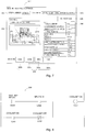
- the NC block execution sequence array 320 is displayed as shown in FIG. 5 .
- a NC block is displayed as one block and NC blocks are displayed in an array in an execution sequence of operations. Therefore, the outline and operation sequence of the operations of the NC program 23a are easily recognized.
- Each NC block has numerical control information and a sequence functional block. The numerical control information is formed of an N number and a command written in the NC language.
- the NC program 23a is executed in block unit at the same time.
- the NC block execution sequence array display means 116e displays a currently executing mark 223 at, for example, an N number portion so that a currently executed NC block is distinguishable from the other blocks.
- the NC block execution sequence array display means 116e is also able to display the NC block execution sequence array 320 in the SFC program form of the sequence program 13a as in the case of the block execution sequence array 300.
- the NC block execution sequence array display means 116e arranges the NC language commands of NC blocks in a vertical direction in an execution sequence, and displays the numerical control information and sequence functional block of each NC language command in parallel with each other as separate blocks.
- the NC block execution sequence array 320 is displayed as shown in FIG. 6 .
- the blocks that are parallel to each other are provided with upper double lines and lower double lines that indicate a parallel branch 231 and a parallel join 232, respectively, so that the form of the NC program is in agreement with the SFC program form of the sequence program 13a. Note that these double lines are not program elements.
- Transitions 421 to 425 are also provided so that the form of the NC program is in agreement with the SFC program form of the sequence program 13a.
- the transitions 421 to 425 represent completion of NC blocks, not program elements.
- the above-described NC block execution sequence array display means 116e makes the background color of a currently executed block different from the background color of the other blocks so that the currently executed block is distinguishable from the other blocks in the SFC program form.
- a machine trouble, or the like occurs during execution of the NC program 23a and execution of the NC program 23a stops, it is possible to easily acquire the NC block at which the NC program 23a stops.
- numerical control information and sequence functional blocks are displayed separately, so it is possible to easily recognize the execution statuses for M code commands.
- the NC block execution sequence array display means 116e is also able to display the NC block execution sequence array 320 in a dialog screen form.
- the NC block execution sequence array display means 116e acquires parameters 344 and a workpiece machining drawing 343 from a database.
- the parameters 344 indicate machining conditions that correspond to a NC functional block.
- the workpiece machining drawing 343 corresponds to the NC functional block.
- a sequence functional block 345 formed of M code commands that correspond to miscellaneous equipments used in the NC functional block is acquired.
- a dialog screen in which the parameters 344, the workpiece machining drawing 343 and the sequence functional block are arranged is displayed.
- the dialog screen of the NC block execution sequence array 320 is displayed as shown in FIG. 7 .
- the parameters 344 of the machining conditions that correspond to the NC functional block are seen while the workpiece machining drawing 343 is referred to.
- the dialog screen is similar to the screen for creating an intended NC functional block in the above-described NC program creating device.
- NC block execution sequence array 320 ( FIG. 5 ) in a list form, in which NC blocks that correspond to the NC functional block are arranged in an execution sequence, or the NC block execution sequence array 320 ( FIG. 6 ) in a SFC program form is displayed on the display unit 110.
- the above-described NC block execution sequence array display means 116e makes the background color of a currently executed block different from the background color of the other blocks so that the currently executed block is distinguishable from the other blocks on the dialogue scrccn.
- sequence functional blocks are separately displayed, so it is possible to easily recognize the execution statuses for M code commands.
- the NC block execution sequence array display means 116e displays the above-described NC block execution sequence array 320 in a SFC program form ( FIG. 6 ) and in a dialog form ( FIG. 7 ).
- the system program 116 calls the control circuit display means 116b.
- the sequence functional block of the M code command (M08) displayed in the SFC program form ( FIG. 6 ) and dialog form ( FIG.
- the control circuit display means 116b acquires a ladder circuit diagram from the programmable controller 10 via the communication interfaces 19, 119. Then, the control circuit that uses the M08 command as an input condition is retrieved from the ladder circuit diagram, and the retrieved control circuit 330 is displayed on the display unit 110. Thus, the control circuit 330 is displayed. By checking the control circuit 330, it is possible to easily recognize the execution status of the miscellaneous equipment.
- the touch panel 122 is used as the selecting means of the block execution sequence display system 100; instead, a mouse, a keyboard, or the like, may be used.
- a block execution sequence display system includes: a machine tool (150) that has numerical control and sequence control; a programmable controller (10) that executes a sequence program (13a); a numerical control device (20) that executes a NC program (23a); block execution sequence array display means (116a) for displaying a block execution sequence array in which sequence functional blocks and a NC program execution block are arranged in an execution sequence; selecting means for selecting one of blocks in the array; and NC functional block execution sequence array display means (116c) for, when the NC program execution block is selected by the selecting means, displaying a NC functional block execution sequence array in which a plurality of NC functional blocks are arranged in an execution sequence.
Landscapes
- Engineering & Computer Science (AREA)
- Physics & Mathematics (AREA)
- General Physics & Mathematics (AREA)
- Automation & Control Theory (AREA)
- Human Computer Interaction (AREA)
- Manufacturing & Machinery (AREA)
- Numerical Control (AREA)
- Programmable Controllers (AREA)
Applications Claiming Priority (1)
| Application Number | Priority Date | Filing Date | Title |
|---|---|---|---|
| JP2011144523A JP5724679B2 (ja) | 2011-06-29 | 2011-06-29 | ブロック実行順表示装置 |
Publications (3)
| Publication Number | Publication Date |
|---|---|
| EP2541351A2 EP2541351A2 (en) | 2013-01-02 |
| EP2541351A3 EP2541351A3 (en) | 2016-03-09 |
| EP2541351B1 true EP2541351B1 (en) | 2021-07-21 |
Family
ID=46851267
Family Applications (1)
| Application Number | Title | Priority Date | Filing Date |
|---|---|---|---|
| EP12172397.7A Active EP2541351B1 (en) | 2011-06-29 | 2012-06-18 | Block execution sequence display system |
Country Status (4)
| Country | Link |
|---|---|
| US (1) | US9483041B2 (ja) |
| EP (1) | EP2541351B1 (ja) |
| JP (1) | JP5724679B2 (ja) |
| CN (1) | CN102854831B (ja) |
Families Citing this family (18)
| Publication number | Priority date | Publication date | Assignee | Title |
|---|---|---|---|---|
| JP5426727B2 (ja) * | 2012-06-15 | 2014-02-26 | ファナック株式会社 | 仮想操作盤を表示する数値制御装置 |
| JP5702811B2 (ja) * | 2013-01-30 | 2015-04-15 | ファナック株式会社 | 動作プログラム作成装置 |
| JP6266268B2 (ja) * | 2013-08-28 | 2018-01-24 | Dmg森精機株式会社 | 表示装置 |
| JP5925976B1 (ja) * | 2014-09-03 | 2016-05-25 | ヤマザキマザック株式会社 | 加工プログラム編集支援装置 |
| JP6742689B2 (ja) * | 2015-01-09 | 2020-08-19 | 株式会社ジェイテクト | 動作プログラム編集装置及びプログラム |
| DE112015006551T5 (de) * | 2015-05-19 | 2018-02-22 | Mitsubishi Electric Corporation | Speicherprogrammierbare Steuerung, Entwicklungswerkzeug und Entwicklungswerkzeugprogramm |
| JP6309927B2 (ja) | 2015-09-16 | 2018-04-11 | ファナック株式会社 | Ncプログラム運転と連動した関連信号の自動トレース機能を有する数値制御装置 |
| US10120363B2 (en) | 2016-02-29 | 2018-11-06 | Fanuc Corporation | Numerical controller for machine tool |
| JP6813381B2 (ja) * | 2017-02-06 | 2021-01-13 | 株式会社日立産機システム | プログラマブルロジックコントローラ |
| JP6568152B2 (ja) * | 2017-06-30 | 2019-08-28 | ファナック株式会社 | 数値制御装置 |
| CN109542048A (zh) * | 2017-09-22 | 2019-03-29 | 科德数控股份有限公司 | 一种数控系统模态g代码的显示方法 |
| JP6760985B2 (ja) * | 2018-03-06 | 2020-09-23 | ファナック株式会社 | 稼働管理装置 |
| JP7151108B2 (ja) * | 2018-03-15 | 2022-10-12 | 株式会社リコー | 情報処理装置、情報処理方法およびプログラム |
| CN108803494A (zh) * | 2018-04-25 | 2018-11-13 | 科德数控股份有限公司 | 数控系统m代码的显示方法 |
| JP7372746B2 (ja) * | 2019-02-20 | 2023-11-01 | Dgshape株式会社 | デンタル加工機の操作装置およびデンタル加工機の操作システム |
| JP7052755B2 (ja) | 2019-02-27 | 2022-04-12 | オムロン株式会社 | 制御装置、管理プログラムおよび制御システム |
| JP2020184179A (ja) * | 2019-05-08 | 2020-11-12 | ファナック株式会社 | 加工制御システム及び加工システム |
| JP7247808B2 (ja) * | 2019-07-31 | 2023-03-29 | オムロン株式会社 | 制御システム、解析方法およびプログラム |
Family Cites Families (16)
| Publication number | Priority date | Publication date | Assignee | Title |
|---|---|---|---|---|
| JPH0760330B2 (ja) * | 1986-06-14 | 1995-06-28 | 三菱電機株式会社 | 複合制御装置 |
| ATE131945T1 (de) | 1989-09-04 | 1996-01-15 | Omron Tateisi Electronics Co | Programmierbare überwachungseinrichtung und verfahren |
| JPH06114678A (ja) * | 1992-09-30 | 1994-04-26 | Toyoda Mach Works Ltd | Nc装置の工具軌跡表示装置 |
| DE4329016A1 (de) * | 1993-08-30 | 1995-03-09 | Heidenhain Gmbh Dr Johannes | Verfahren zur Erstellung und/oder Änderung von NC-Programmen |
| US5485620A (en) * | 1994-02-25 | 1996-01-16 | Automation System And Products, Inc. | Integrated control system for industrial automation applications |
| JP3679844B2 (ja) * | 1995-11-09 | 2005-08-03 | ファナック株式会社 | シーケンス・プログラムの実行装置 |
| JP2001005504A (ja) | 1999-06-18 | 2001-01-12 | Mitsubishi Electric Corp | モーションコントローラおよびモーションコントローラ用周辺装置 |
| JP2001100817A (ja) * | 1999-09-30 | 2001-04-13 | Toyoda Mach Works Ltd | シーケンシャル・ファンクション・チャート式プログラマブル・コントローラにおける監視装置 |
| JP3700529B2 (ja) * | 2000-03-31 | 2005-09-28 | 豊田工機株式会社 | シーケンス・コントローラ |
| US6981226B2 (en) | 2000-08-07 | 2005-12-27 | Siemens Aktiengesellschaft | Flowchart programming for industrial controllers, in particular motion controllers |
| DE10149147A1 (de) * | 2001-10-04 | 2003-04-17 | Heidenhain Gmbh Dr Johannes | Verfahren und Vorrichtung zum Erstellen oder Ändern von NC-Programmen |
| JP2003186506A (ja) * | 2001-12-17 | 2003-07-04 | Toyoda Mach Works Ltd | シーケンスコントローラのモニタ装置 |
| US7117052B2 (en) * | 2003-02-18 | 2006-10-03 | Fisher-Rosemount Systems, Inc. | Version control for objects in a process plant configuration system |
| JP2007058607A (ja) * | 2005-08-24 | 2007-03-08 | Fujitsu Ltd | 表示装置、表示方法、および、表示プログラム |
| JP4959498B2 (ja) * | 2007-09-27 | 2012-06-20 | 富士フイルム株式会社 | 画像表示装置、画像表示方法、プログラム及び撮影装置 |
| DE102009004285A1 (de) * | 2008-06-27 | 2009-12-31 | Robert Bosch Gmbh | Verfahren und Vorrichtung zur Optimierung, Überwachung oder Analyse eines Prozesses |
-
2011
- 2011-06-29 JP JP2011144523A patent/JP5724679B2/ja active Active
-
2012
- 2012-05-31 CN CN201210177000.XA patent/CN102854831B/zh active Active
- 2012-06-08 US US13/491,919 patent/US9483041B2/en active Active
- 2012-06-18 EP EP12172397.7A patent/EP2541351B1/en active Active
Non-Patent Citations (1)
| Title |
|---|
| None * |
Also Published As
| Publication number | Publication date |
|---|---|
| EP2541351A3 (en) | 2016-03-09 |
| US9483041B2 (en) | 2016-11-01 |
| EP2541351A2 (en) | 2013-01-02 |
| US20130006391A1 (en) | 2013-01-03 |
| CN102854831A (zh) | 2013-01-02 |
| CN102854831B (zh) | 2017-12-08 |
| JP2013012050A (ja) | 2013-01-17 |
| JP5724679B2 (ja) | 2015-05-27 |
Similar Documents
| Publication | Publication Date | Title |
|---|---|---|
| EP2541351B1 (en) | Block execution sequence display system | |
| US9733637B2 (en) | Method and apparatus for automated configuration of a monitoring function of a machine tool | |
| EP0606649B1 (en) | Numerically controlled machine tool and method to re-execute a machining program after it has been stopped | |
| US9802286B2 (en) | Robot control system provided in machining system including robot and machine tool | |
| CN202306251U (zh) | 控制机床重新启动自动操作的装置 | |
| US20060229761A1 (en) | Numerical controller | |
| EP1624352B1 (en) | Manual restart learning process and manual restart process for an automated system | |
| EP2541355A1 (en) | Machine control program creating device | |
| US9823648B2 (en) | Method and apparatus for an automated configuration of a monitoring function of an industrial robot | |
| JP2012510099A (ja) | 安全制御装置用ユーザープログラムの作成方法および装置 | |
| US7102622B2 (en) | Production equipment monitoring device | |
| KR100789330B1 (ko) | 시퀀셜 기능 차트식 프로그래머블 컨트롤러에 있어서의감시장치 | |
| CN105408823A (zh) | 工程设计工具、程序编辑装置以及程序编辑系统 | |
| JP2006107043A (ja) | 工作機械制御装置 | |
| US10108171B2 (en) | Numerical controller capable of specifying halt point | |
| KR20180081774A (ko) | 매니퓰레이터 프로그램의 그래픽 사용자 인터페이스를 만들기 위한 방법 및 컴퓨터 프로그램 | |
| US10055112B2 (en) | Control panel | |
| JP2012198775A (ja) | ロボットプログラミング装置および方法 | |
| JP2001154709A (ja) | Plc用の操作盤及び同操作盤における異常表示方法 | |
| CN106155519B (zh) | 画面信息生成装置 | |
| CN105785902A (zh) | 操作程序编辑装置和用于编辑操作程序的方法 | |
| CN104656552A (zh) | 六轴数控抛光机cnc系统的移动式无线调试终端及其操作方法 | |
| WO2022244070A1 (ja) | 稼働状況表示装置、およびコンピュータ読み取り可能な記憶媒体 | |
| CN105785970A (zh) | 用于可编程控制器的监测装置 | |
| JPH02309405A (ja) | 数値制御装置および数値制御装置の画面表示方法 |
Legal Events
| Date | Code | Title | Description |
|---|---|---|---|
| PUAI | Public reference made under article 153(3) epc to a published international application that has entered the european phase |
Free format text: ORIGINAL CODE: 0009012 |
|
| AK | Designated contracting states |
Kind code of ref document: A2 Designated state(s): AL AT BE BG CH CY CZ DE DK EE ES FI FR GB GR HR HU IE IS IT LI LT LU LV MC MK MT NL NO PL PT RO RS SE SI SK SM TR |
|
| AX | Request for extension of the european patent |
Extension state: BA ME |
|
| PUAL | Search report despatched |
Free format text: ORIGINAL CODE: 0009013 |
|
| AK | Designated contracting states |
Kind code of ref document: A3 Designated state(s): AL AT BE BG CH CY CZ DE DK EE ES FI FR GB GR HR HU IE IS IT LI LT LU LV MC MK MT NL NO PL PT RO RS SE SI SK SM TR |
|
| AX | Request for extension of the european patent |
Extension state: BA ME |
|
| RIC1 | Information provided on ipc code assigned before grant |
Ipc: G05B 19/409 20060101ALI20160203BHEP Ipc: G05B 19/05 20060101AFI20160203BHEP |
|
| 17P | Request for examination filed |
Effective date: 20160901 |
|
| STAA | Information on the status of an ep patent application or granted ep patent |
Free format text: STATUS: EXAMINATION IS IN PROGRESS |
|
| 17Q | First examination report despatched |
Effective date: 20180829 |
|
| STAA | Information on the status of an ep patent application or granted ep patent |
Free format text: STATUS: EXAMINATION IS IN PROGRESS |
|
| GRAP | Despatch of communication of intention to grant a patent |
Free format text: ORIGINAL CODE: EPIDOSNIGR1 |
|
| STAA | Information on the status of an ep patent application or granted ep patent |
Free format text: STATUS: GRANT OF PATENT IS INTENDED |
|
| INTG | Intention to grant announced |
Effective date: 20210412 |
|
| GRAS | Grant fee paid |
Free format text: ORIGINAL CODE: EPIDOSNIGR3 |
|
| GRAA | (expected) grant |
Free format text: ORIGINAL CODE: 0009210 |
|
| STAA | Information on the status of an ep patent application or granted ep patent |
Free format text: STATUS: THE PATENT HAS BEEN GRANTED |
|
| AK | Designated contracting states |
Kind code of ref document: B1 Designated state(s): AL AT BE BG CH CY CZ DE DK EE ES FI FR GB GR HR HU IE IS IT LI LT LU LV MC MK MT NL NO PL PT RO RS SE SI SK SM TR |
|
| REG | Reference to a national code |
Ref country code: GB Ref legal event code: FG4D |
|
| REG | Reference to a national code |
Ref country code: CH Ref legal event code: EP |
|
| REG | Reference to a national code |
Ref country code: DE Ref legal event code: R096 Ref document number: 602012076141 Country of ref document: DE |
|
| REG | Reference to a national code |
Ref country code: AT Ref legal event code: REF Ref document number: 1413147 Country of ref document: AT Kind code of ref document: T Effective date: 20210815 |
|
| REG | Reference to a national code |
Ref country code: IE Ref legal event code: FG4D |
|
| REG | Reference to a national code |
Ref country code: LT Ref legal event code: MG9D |
|
| REG | Reference to a national code |
Ref country code: NL Ref legal event code: MP Effective date: 20210721 |
|
| REG | Reference to a national code |
Ref country code: AT Ref legal event code: MK05 Ref document number: 1413147 Country of ref document: AT Kind code of ref document: T Effective date: 20210721 |
|
| PG25 | Lapsed in a contracting state [announced via postgrant information from national office to epo] |
Ref country code: LT Free format text: LAPSE BECAUSE OF FAILURE TO SUBMIT A TRANSLATION OF THE DESCRIPTION OR TO PAY THE FEE WITHIN THE PRESCRIBED TIME-LIMIT Effective date: 20210721 Ref country code: BG Free format text: LAPSE BECAUSE OF FAILURE TO SUBMIT A TRANSLATION OF THE DESCRIPTION OR TO PAY THE FEE WITHIN THE PRESCRIBED TIME-LIMIT Effective date: 20211021 Ref country code: AT Free format text: LAPSE BECAUSE OF FAILURE TO SUBMIT A TRANSLATION OF THE DESCRIPTION OR TO PAY THE FEE WITHIN THE PRESCRIBED TIME-LIMIT Effective date: 20210721 Ref country code: NL Free format text: LAPSE BECAUSE OF FAILURE TO SUBMIT A TRANSLATION OF THE DESCRIPTION OR TO PAY THE FEE WITHIN THE PRESCRIBED TIME-LIMIT Effective date: 20210721 Ref country code: NO Free format text: LAPSE BECAUSE OF FAILURE TO SUBMIT A TRANSLATION OF THE DESCRIPTION OR TO PAY THE FEE WITHIN THE PRESCRIBED TIME-LIMIT Effective date: 20211021 Ref country code: PT Free format text: LAPSE BECAUSE OF FAILURE TO SUBMIT A TRANSLATION OF THE DESCRIPTION OR TO PAY THE FEE WITHIN THE PRESCRIBED TIME-LIMIT Effective date: 20211122 Ref country code: RS Free format text: LAPSE BECAUSE OF FAILURE TO SUBMIT A TRANSLATION OF THE DESCRIPTION OR TO PAY THE FEE WITHIN THE PRESCRIBED TIME-LIMIT Effective date: 20210721 Ref country code: ES Free format text: LAPSE BECAUSE OF FAILURE TO SUBMIT A TRANSLATION OF THE DESCRIPTION OR TO PAY THE FEE WITHIN THE PRESCRIBED TIME-LIMIT Effective date: 20210721 Ref country code: FI Free format text: LAPSE BECAUSE OF FAILURE TO SUBMIT A TRANSLATION OF THE DESCRIPTION OR TO PAY THE FEE WITHIN THE PRESCRIBED TIME-LIMIT Effective date: 20210721 Ref country code: HR Free format text: LAPSE BECAUSE OF FAILURE TO SUBMIT A TRANSLATION OF THE DESCRIPTION OR TO PAY THE FEE WITHIN THE PRESCRIBED TIME-LIMIT Effective date: 20210721 Ref country code: SE Free format text: LAPSE BECAUSE OF FAILURE TO SUBMIT A TRANSLATION OF THE DESCRIPTION OR TO PAY THE FEE WITHIN THE PRESCRIBED TIME-LIMIT Effective date: 20210721 |
|
| PG25 | Lapsed in a contracting state [announced via postgrant information from national office to epo] |
Ref country code: PL Free format text: LAPSE BECAUSE OF FAILURE TO SUBMIT A TRANSLATION OF THE DESCRIPTION OR TO PAY THE FEE WITHIN THE PRESCRIBED TIME-LIMIT Effective date: 20210721 Ref country code: LV Free format text: LAPSE BECAUSE OF FAILURE TO SUBMIT A TRANSLATION OF THE DESCRIPTION OR TO PAY THE FEE WITHIN THE PRESCRIBED TIME-LIMIT Effective date: 20210721 Ref country code: GR Free format text: LAPSE BECAUSE OF FAILURE TO SUBMIT A TRANSLATION OF THE DESCRIPTION OR TO PAY THE FEE WITHIN THE PRESCRIBED TIME-LIMIT Effective date: 20211022 |
|
| RAP4 | Party data changed (patent owner data changed or rights of a patent transferred) |
Owner name: JTEKT CORPORATION |
|
| REG | Reference to a national code |
Ref country code: DE Ref legal event code: R097 Ref document number: 602012076141 Country of ref document: DE |
|
| PG25 | Lapsed in a contracting state [announced via postgrant information from national office to epo] |
Ref country code: DK Free format text: LAPSE BECAUSE OF FAILURE TO SUBMIT A TRANSLATION OF THE DESCRIPTION OR TO PAY THE FEE WITHIN THE PRESCRIBED TIME-LIMIT Effective date: 20210721 |
|
| PLBE | No opposition filed within time limit |
Free format text: ORIGINAL CODE: 0009261 |
|
| STAA | Information on the status of an ep patent application or granted ep patent |
Free format text: STATUS: NO OPPOSITION FILED WITHIN TIME LIMIT |
|
| PG25 | Lapsed in a contracting state [announced via postgrant information from national office to epo] |
Ref country code: SM Free format text: LAPSE BECAUSE OF FAILURE TO SUBMIT A TRANSLATION OF THE DESCRIPTION OR TO PAY THE FEE WITHIN THE PRESCRIBED TIME-LIMIT Effective date: 20210721 Ref country code: SK Free format text: LAPSE BECAUSE OF FAILURE TO SUBMIT A TRANSLATION OF THE DESCRIPTION OR TO PAY THE FEE WITHIN THE PRESCRIBED TIME-LIMIT Effective date: 20210721 Ref country code: RO Free format text: LAPSE BECAUSE OF FAILURE TO SUBMIT A TRANSLATION OF THE DESCRIPTION OR TO PAY THE FEE WITHIN THE PRESCRIBED TIME-LIMIT Effective date: 20210721 Ref country code: EE Free format text: LAPSE BECAUSE OF FAILURE TO SUBMIT A TRANSLATION OF THE DESCRIPTION OR TO PAY THE FEE WITHIN THE PRESCRIBED TIME-LIMIT Effective date: 20210721 Ref country code: CZ Free format text: LAPSE BECAUSE OF FAILURE TO SUBMIT A TRANSLATION OF THE DESCRIPTION OR TO PAY THE FEE WITHIN THE PRESCRIBED TIME-LIMIT Effective date: 20210721 Ref country code: AL Free format text: LAPSE BECAUSE OF FAILURE TO SUBMIT A TRANSLATION OF THE DESCRIPTION OR TO PAY THE FEE WITHIN THE PRESCRIBED TIME-LIMIT Effective date: 20210721 |
|
| 26N | No opposition filed |
Effective date: 20220422 |
|
| PG25 | Lapsed in a contracting state [announced via postgrant information from national office to epo] |
Ref country code: IT Free format text: LAPSE BECAUSE OF FAILURE TO SUBMIT A TRANSLATION OF THE DESCRIPTION OR TO PAY THE FEE WITHIN THE PRESCRIBED TIME-LIMIT Effective date: 20210721 |
|
| PG25 | Lapsed in a contracting state [announced via postgrant information from national office to epo] |
Ref country code: MC Free format text: LAPSE BECAUSE OF FAILURE TO SUBMIT A TRANSLATION OF THE DESCRIPTION OR TO PAY THE FEE WITHIN THE PRESCRIBED TIME-LIMIT Effective date: 20210721 |
|
| REG | Reference to a national code |
Ref country code: CH Ref legal event code: PL |
|
| REG | Reference to a national code |
Ref country code: BE Ref legal event code: MM Effective date: 20220630 |
|
| GBPC | Gb: european patent ceased through non-payment of renewal fee |
Effective date: 20220618 |
|
| PG25 | Lapsed in a contracting state [announced via postgrant information from national office to epo] |
Ref country code: LU Free format text: LAPSE BECAUSE OF NON-PAYMENT OF DUE FEES Effective date: 20220618 Ref country code: LI Free format text: LAPSE BECAUSE OF NON-PAYMENT OF DUE FEES Effective date: 20220630 Ref country code: IE Free format text: LAPSE BECAUSE OF NON-PAYMENT OF DUE FEES Effective date: 20220618 Ref country code: FR Free format text: LAPSE BECAUSE OF NON-PAYMENT OF DUE FEES Effective date: 20220630 Ref country code: CH Free format text: LAPSE BECAUSE OF NON-PAYMENT OF DUE FEES Effective date: 20220630 |
|
| PG25 | Lapsed in a contracting state [announced via postgrant information from national office to epo] |
Ref country code: GB Free format text: LAPSE BECAUSE OF NON-PAYMENT OF DUE FEES Effective date: 20220618 Ref country code: BE Free format text: LAPSE BECAUSE OF NON-PAYMENT OF DUE FEES Effective date: 20220630 |
|
| PGFP | Annual fee paid to national office [announced via postgrant information from national office to epo] |
Ref country code: DE Payment date: 20230502 Year of fee payment: 12 |
|
| PG25 | Lapsed in a contracting state [announced via postgrant information from national office to epo] |
Ref country code: HU Free format text: LAPSE BECAUSE OF FAILURE TO SUBMIT A TRANSLATION OF THE DESCRIPTION OR TO PAY THE FEE WITHIN THE PRESCRIBED TIME-LIMIT; INVALID AB INITIO Effective date: 20120618 |
|
| PG25 | Lapsed in a contracting state [announced via postgrant information from national office to epo] |
Ref country code: MK Free format text: LAPSE BECAUSE OF FAILURE TO SUBMIT A TRANSLATION OF THE DESCRIPTION OR TO PAY THE FEE WITHIN THE PRESCRIBED TIME-LIMIT Effective date: 20210721 Ref country code: CY Free format text: LAPSE BECAUSE OF FAILURE TO SUBMIT A TRANSLATION OF THE DESCRIPTION OR TO PAY THE FEE WITHIN THE PRESCRIBED TIME-LIMIT Effective date: 20210721 |