EP2535113A2 - Vorrichtung zum Schneiden von Gebinden - Google Patents
Vorrichtung zum Schneiden von Gebinden Download PDFInfo
- Publication number
- EP2535113A2 EP2535113A2 EP12002593A EP12002593A EP2535113A2 EP 2535113 A2 EP2535113 A2 EP 2535113A2 EP 12002593 A EP12002593 A EP 12002593A EP 12002593 A EP12002593 A EP 12002593A EP 2535113 A2 EP2535113 A2 EP 2535113A2
- Authority
- EP
- European Patent Office
- Prior art keywords
- conveyor body
- container
- screw conveyor
- cutting
- screw
- Prior art date
- Legal status (The legal status is an assumption and is not a legal conclusion. Google has not performed a legal analysis and makes no representation as to the accuracy of the status listed.)
- Granted
Links
- 235000013361 beverage Nutrition 0.000 claims description 4
- 239000004484 Briquette Substances 0.000 claims description 2
- 238000010200 validation analysis Methods 0.000 description 4
- 238000010276 construction Methods 0.000 description 2
- 238000000034 method Methods 0.000 description 2
- 230000015556 catabolic process Effects 0.000 description 1
- 230000006835 compression Effects 0.000 description 1
- 238000007906 compression Methods 0.000 description 1
- 238000005202 decontamination Methods 0.000 description 1
- 230000003588 decontaminative effect Effects 0.000 description 1
- 238000011038 discontinuous diafiltration by volume reduction Methods 0.000 description 1
- 239000002184 metal Substances 0.000 description 1
- 239000010813 municipal solid waste Substances 0.000 description 1
- 238000004806 packaging method and process Methods 0.000 description 1
- 238000009966 trimming Methods 0.000 description 1
Images

Classifications
-
- B—PERFORMING OPERATIONS; TRANSPORTING
- B02—CRUSHING, PULVERISING, OR DISINTEGRATING; PREPARATORY TREATMENT OF GRAIN FOR MILLING
- B02C—CRUSHING, PULVERISING, OR DISINTEGRATING IN GENERAL; MILLING GRAIN
- B02C19/00—Other disintegrating devices or methods
- B02C19/22—Crushing mills with screw-shaped crushing means
-
- B—PERFORMING OPERATIONS; TRANSPORTING
- B02—CRUSHING, PULVERISING, OR DISINTEGRATING; PREPARATORY TREATMENT OF GRAIN FOR MILLING
- B02C—CRUSHING, PULVERISING, OR DISINTEGRATING IN GENERAL; MILLING GRAIN
- B02C19/00—Other disintegrating devices or methods
- B02C19/0056—Other disintegrating devices or methods specially adapted for specific materials not otherwise provided for
- B02C19/0081—Other disintegrating devices or methods specially adapted for specific materials not otherwise provided for specially adapted for breaking-up bottles
-
- B—PERFORMING OPERATIONS; TRANSPORTING
- B30—PRESSES
- B30B—PRESSES IN GENERAL
- B30B9/00—Presses specially adapted for particular purposes
- B30B9/32—Presses specially adapted for particular purposes for consolidating scrap metal or for compacting used cars
- B30B9/321—Presses specially adapted for particular purposes for consolidating scrap metal or for compacting used cars for consolidating empty containers, e.g. cans
-
- B—PERFORMING OPERATIONS; TRANSPORTING
- B30—PRESSES
- B30B—PRESSES IN GENERAL
- B30B9/00—Presses specially adapted for particular purposes
- B30B9/32—Presses specially adapted for particular purposes for consolidating scrap metal or for compacting used cars
- B30B9/327—Presses specially adapted for particular purposes for consolidating scrap metal or for compacting used cars for briquetting scrap metal
Definitions
- the invention relates to a device for the decontamination of containers, in particular accepted at a reverse vending machines beverage containers, with a driven about a rotation axis conveyor body for deforming and / or transporting of the conveyor body in a feed direction supplied containers, with a conveyor body associated cutting unit for crushing the container and with a defined by the conveyor body and the cutting unit deformation space in which the containers are at least partially provided during comminution.
- From the DE 10 2009 026 184 A1 is a device for the validation of containers, in particular of emptied beverage containers made of plastic or metal known.
- Such devaluation devices are provided, for example, in conjunction with reverse vending machines with the aim of irreversibly deforming or shredding returned disposable containers.
- the deformation or comminution ensures that a once returned container is not returned again and the deposit value of the container is misused twice.
- the volume is reduced by deforming or crushing the container.
- the storage or the return transport of the returned container designed by this particularly economical.
- the cancellation device has two rotatably supported conveyor body with cam-like cutting.
- the axes of rotation of the two conveyor bodies are arranged parallel and spaced from each other. The distance between the axes of rotation is so dimensioned and the direction of rotation of the conveyor body is determined so that a container to be depreciated due to the rotation of the conveyor body fed independently and deformed or crushed in a deformation space formed between the conveyor body.
- the devaluation unit has proven itself in practice.
- a two-stage devaluation and compacting process is increasingly provided, by means of which the containers are first reliably devalued and optionally pre-compacted and then reduced to a high degree in their volume.
- the volume reduction which is modeled on the cancellation, takes place, for example, in a so-called briquetting unit, that is to say in a press which forms highly compressed briquettes from the depreciated containers.
- Object of the present invention is therefore to develop a device for the validation of containers in such a way that the devalued container can be supplied to a briquetting unit in a particularly simple manner.
- the invention is characterized in connection with the preamble of claim 1, characterized in that the conveyor body is designed as a screw conveyor with a worm shaft and with a helically extending around the worm shaft screw thread, wherein the screw conveyor body is arranged in a screw trough, which surrounds the screw conveyor body at least partially shell side and at least one recess has for feeding the container to the deformation space.
- the particular advantage of the invention is that the containers are first crushed by means of the cutting unit and then can be fed through the screw conveyor body continuously or uniformly a Brikettieriki or other suitable Kompaktierü.
- the Brikettieriens is protected in this respect from strong and sudden load fluctuations and can be dimensioned in a particularly economical manner.
- the screw conveyor body is suitable for the removal of the shredded containers, since a further compression of the containers in the screw conveyor body can take place during the removal.
- a maximum container size is possible Are defined.
- the briquetting unit or the other compacting unit can be protected, as it were from the system, from being overloaded by too many or too large pack parts. Damage and failure of the briquetting unit is effectively prevented.
- a height of the worm thread is dimensioned such that a smallest permissible container supplied to the worm conveyor body is severed at least twice by the cutting unit of the wiping device to form at least three container parts.
- DPG Deutsche Pfandsystem GmbH
- the cutting unit on a provided on the screw conveyor body co-rotating knife with a cutting edge.
- the cutting edge is at least partially arranged between two adjacent threads of the worm thread.
- the knife is provided between two adjacent thread crests of the worm thread.
- a structurally simple construction of the device can be ensured by the provision of the co-rotating knife on the cutting body.
- the conveyor body and the cutting unit can be actuated by means of a single drive.
- the cutting unit in addition to the co-rotating knife on a fixed knife with a cutting edge.
- the fixed knife is associated with the co-rotating knife so that each revolution of the screw conveyor body, the rotating knife is once passed by the fixed knife for the transection of the container.
- the cutting performance is improved by the provision of the second knife.
- the second knife is designed as a fixed knife, a simple construction is realized at the same time.
- the fixed knife can be held, for example, on the likewise stationary screw trough or on a holding device provided specifically for the fixed knife.
- the recess provided in the screw trough is assigned a guide unit.
- the containers are supported when feeding them or aligned in the feed direction.
- a known orientation of the container in the deformation space is achieved by the orientation of the container and allows a defined division of the same.
- jamming of the containers in the area of the guide unit or of the deformation space can be avoided by the protection and alignment of the containers and a blockage or a breakdown of the devaluation device caused thereby can be prevented.
- the screw trough has a plurality of recesses and the worm conveyor body has a number of cutters corresponding to the number of recesses.
- the cutting units are each associated with a recess.
- the recesses and the cutting units are spaced from each other in the axial direction of the screw conveyor body.
- a plurality of reverse vending machines can be associated with a single devaluation device.
- the containers introduced at various return machines are fed to the screw conveyor body at different locations and supplied by the common screw conveyor body to a common briquetting unit. The devaluation and briquetting of a variety of containers can thus be particularly economical and space-saving.
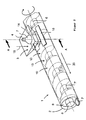
- a device for debasing containers 7 after FIGS. 1 and 2 has as essential components a screw conveyor body 1, a screw conveyor trough 2 surrounding the screw conveyor body 1 with a recess 3, a guide unit 4 assigned to the recess 3 and a cutting unit 5.
- the cutting unit 5 is like the guide unit 4 spatially associated with the recess 3.
- the screw conveyor body 1 is rotatably mounted about a rotation axis 6 of the device and by means of a drive unit, not shown, for example by means of an electric drive, driven.
- Such devaluation devices are associated, for example, reverse vending machines, which are provided for example in a retail store and serve the return of beverage packaging (container 7).
- the devaluation device is used to devaluate the container 7 after the return, that is to deform and / or to crush into a plurality of container parts 7 '. By devaluing the volume of the container 7 is reduced while ensuring that the container 7 can not be repeatedly returned with the result that the deposit value is paid several times.
- the container parts 7 ' are after the devaluation, for example, a non-illustrated Briquette unit, another compacting unit or other stock for devalued container 7 or container parts 7 'supplied.
- the devaluation device is provided in a warehouse or storage space of the retailer that is not accessible to the customer.
- the screw conveyor body 1 has a coaxial with the axis of rotation 6 oriented screw shaft 8 and a helically extending around the worm shaft 8 screw thread 9.
- the worm thread 9 has a height 11 measured from the cylinder jacket surface of the worm shaft 8 to a thread crest 10 of the worm thread 9 and, as a further characteristic variable, a width 12 of a worm thread notch 13 formed between two adjacent threads.
- the worm thread notch 13 can, for example, be in a longitudinal section of the worm conveyer body 1 have a substantially rectangular or trapezoidal geometry.
- the screw trough 2 is formed substantially cylindrical and surrounds the screw conveyor body 1 shell side.
- the screw trough 2 may be formed in one or more parts. It can have a different shape than a cylindrical one.
- the screw trough 2 may be channel-shaped and surround the screw conveyor body 1 only on a lower side of the same shell side.
- the screw trough 2 is arranged stationary.
- the cutting unit 5 has a co-rotating first knife 14 with a cutting edge 15 and a fixed arranged further knife 16 with a further cutting edge 17.
- the co-rotating knife 14 is provided on the rotating screw conveyor body 1 and fixedly connected thereto.
- the rotating blade 14 extends between two adjacent threads of the worm thread 9, in the region of the thread crests 10 of the worm thread 9 assigned to the adjacent threads.
- the fixed knife 16 is fastened to the stationary worm trough 2.
- the cutting edge 15 of the rotating blade 14 extends as well the cutting edge 17 of the fixed blade 16 in the direction of the axis of rotation 6 of the screw conveyor body 1.
- the cutting 15, 17 are oriented parallel to the axis of rotation 6 of the screw conveyor body 1.
- the cutting edges 15, 17 can be arranged angularly offset from one another and / or to the axis of rotation 6 of the screw conveyor body 1.
- the guide unit 4 is formed in the manner of a rectangular funnel.
- the funnel 4 tapers in the direction of the recess 3. It serves to support the screw conveyor body 1 in a feed direction 18 supplied container 7 during feeding and align. For example, it can be effected by means of the guide funnel 4 that the containers 7 are fed to the screw conveyor body 1 in the longitudinal direction, in particular with a container bottom.
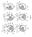
- the devaluation of the container 7 takes place in the in FIG. 3 illustrated steps.
- the container 7 is fed to a defined by the screw conveyor body 1 and the cutting unit 5 deformation space 19 in the feed direction 18.
- the container 7 is not completely immersed in the screw conveyor body 1. Rather, the container 7 is supported with the container bottom on the worm shaft 8.
- the rotating blade 14 with its cutting edge 15 on the shell side occurs on the container 7.
- the container 7 is first fixed due to the further rotation of the screw conveyor body 1 between the rotating blade 14 and the fixed blade 16 and at severed further rotation.
- the rotating blade 14 per revolution of the screw conveyor body 1 once passed the fixed blade 16 of the cutting unit 5 and the container part 7 'separated from the container 7.
- An immediate subsequent slipping of a not yet shredded residual trash portion 7 "into the deformation space 19 is prevented by the geometry of the screw thread 9.
- the residual trimming portion 7" is supported on the thread crest 10 of the screw thread. Only with continued rotation of the screw conveyor body 1 about the rotation axis 6, the worm thread 9 moves in such a way that the residual container section 7 "can slip into the deformation space 19. The process is then repeated.
- the feed direction 18 is oriented perpendicular to the axial direction 20.
- the height 11 of the worm thread 9 is dimensioned such that a smallest permissible container 7, which can be returned to the associated reverse vending machine, reduced in at least three container parts 7 ', that is twice severed. As a result, a sufficient devaluation of the container 7 in the sense of the relevant guidelines of the DPG is achieved.
- the width 12 of the thread groove 13 is dimensioned so that a largest permissible container 7 can be safely introduced into the deformation space 19.
Landscapes
- Engineering & Computer Science (AREA)
- Mechanical Engineering (AREA)
- Food Science & Technology (AREA)
- Screw Conveyors (AREA)
- Crushing And Pulverization Processes (AREA)
Abstract
Description
- Die Erfindung betrifft eine Vorrichtung zum Entwerten von Gebinden, insbesondere von an einem Leergutrücknahmeautomaten entgegengenommenen Getränkeverpackungen, mit einem um eine Rotationsachse antreibbaren Förderkörper zum Verformen und/oder Transportieren von dem Förderkörper in eine Zuführrichtung zugeführten Gebinden, mit einer dem Förderkörper zugeordneten Schneideinheit zum Zerkleinern der Gebinde und mit einem durch den Förderkörper und die Schneideinheit definierten Verformungsraum, in dem die Gebinde zumindest abschnittsweise während der Zerkleinerung vorgesehen sind.
- Aus der
DE 10 2009 026 184 A1 ist eine Vorrichtung zum Entwerten von Gebinden, insbesondere von entleerten Getränkeverpackungen aus Kunststoff oder Metall bekannt. Derartige Entwertungsvorrichtungen werden beispielsweise in Verbindung mit Leergutrücknahmeautomaten vorgesehen mit dem Ziel, zurückgegebene Einweggebinde irreversibel zu verformen bzw. zu zerkleinern. Durch die Verformung bzw. Zerkleinerung wird sichergestellt, dass ein einmal zurückgegebenes Gebinde nicht erneut zurückgegeben und der Pfandwert des Gebindes missbräuchlich zweimal ausgezahlt wird. Zudem wird durch das Verformen bzw. Zerkleinern des Gebindes dessen Volumen reduziert. Die Lagerung bzw. der Rücktransport der zurückgenommenen Gebinde gestaltet sich hierdurch besonders wirtschaftlich. - Die Entwertungsvorrichtung weist zwei drehbar gehaltene Förderkörper mit nockenartigen Schneiden auf. Die Rotationsachsen der beiden Förderkörper sind parallel und beabstandet zueinander angeordnet. Der Abstand der Rotationsachsen ist so bemessen und die Drehrichtung der Förderkörper so bestimmt, dass ein zu entwertendes Gebinde infolge der Rotation der Förderkörper selbständig eingezogen und in einem zwischen dem Förderkörper gebildeten Verformungsraum verformt bzw. zerkleinert wird.
- Grundsätzlich hat sich die Entwertungseinheit in der Praxis bewährt. Jedoch wird zur weiteren Volumenreduktion in zunehmender Weise ein zweistufiger Entwertungs- und Kompaktierprozess vorgesehen, durch den die Gebinde zunächst zuverlässig entwertet und gegebenenfalls vorkompaktiert und dann in hohem Maß in ihrem Volumen reduziert werden. Die der Entwertung nachgestaltete Volumenreduzierung erfolgt beispielsweise in einer sogenannten Brikettiereinheit, das heißt in einer Presse, die aus den entwerteten Gebinden hochverdichtete Briketts formt.
- Aufgabe der vorliegenden Erfindung ist es daher, eine Vorrichtung zur Entwertung von Gebinden derart weiterzubilden, dass die entwerteten Gebinde in besonders einfacher Weise einer Brikettiereinheit zugeführt werden können.
- Zur Lösung der Aufgabe ist die Erfindung in Verbindung mit dem Oberbegriff des Patentanspruchs 1 dadurch gekennzeichnet, dass der Förderkörper als ein Schneckenförderkörper ausgebildet ist mit einer Schneckenwelle und mit einem sich schraubenlinienförmig um die Schneckenwelle erstreckenden Schneckengewinde, wobei der Schneckenförderkörper in einem Schneckentrog angeordnet ist, welcher den Schneckenförderkörper zumindest abschnittsweise mantelseitig umgibt und wenigstens eine Ausnehmung aufweist zum Zuführen der Gebinde zu dem Verformungsraum.
- Der besondere Vorteil der Erfindung besteht darin, dass die Gebinde mittels der Schneideinheit zunächst zerkleinert werden und sich dann durch den Schneckenförderkörper kontinuierlich bzw. gleichförmig einer Brikettiereinheit oder einer anderen geeigneten Kompaktiereinheit zuführen lassen. Die Brikettiereinheit wird insofern vor starken und plötzlichen Lastschwankungen geschützt und kann in besonders wirtschaftlicher Weise dimensioniert werden. Insbesondere eignet sich der Schneckenförderkörper für den Abtransport der zerkleinerten Gebinde, da während des Abtransports eine weitere Verdichtung der Gebinde in dem Schneckenförderkörper stattfinden kann. Zugleich ist aufgrund der Geometrie von Schneckenförderkörper und Schneckentrog eine maximale Gebindegröße definiert. Insofern kann die Brikettiereinheit bzw. die sonstige Kompaktiereinheit quasi systemimmanent vor einer Überlastung durch zu viele bzw. zu große Gebindeteile geschützt werden. Einer Schädigung und einem Ausfall der Brikettiereinheit ist wirkungsvoll vorgebeugt.
- Nach einer besonderen Ausführungsform der Erfindung ist eine Höhe des Schneckengewindes derart bemessen, dass ein dem Schneckenförderkörper zugeführtes, kleinstes zulässiges Gebinde von der Schneideinheit der Entwertungsvorrichtung wenigstens zweimal durchtrennt wird zur Bildung von wenigstens drei Gebindeteilen. Indem durch die Geometrie des Schneckengetriebes sichergestellt ist, dass jedes Gebinde wenigstens zweimal zerschnitten wird, ist den einschlägigen Richtlinien der Deutsche Pfandsystem GmbH (DPG) hinsichtlich der geforderten Entwertung genüge getan. Beispielsweise kann aber auch vorgesehen sein, dass auch das kleinste zulässige Gebinde in mehr als drei Gebindeteile zerschnitten wird.
- Nach einer Weiterbildung der Erfindung weist die Schneideinheit ein an dem Schneckenförderkörper vorgesehenes, mitrotierendes Messer mit einer Schneide auf. Die Schneide ist zumindest abschnittsweise zwischen zwei benachbarten Gewindegängen des Schneckengewindes angeordnet. Beispielsweise ist das Messer zwischen zwei benachbarten Gewindespitzen des Schneckengewindes vorgesehen. Vorteilhaft kann durch das Vorsehen des mitrotierenden Messers an dem Schneidenkörper ein konstruktiv einfacher Aufbau der Vorrichtung gewährleistet werden. Insbesondere kann auf einen separaten Messerantrieb verzichtet werden. Hierdurch reduziert sich die Anzahl der Bauteile und die Komplexität der Vorrichtung. Zudem können mittels eines einzigen Antriebs der Förderkörper und die Schneideinheit betätigt werden.
- Nach einer Weiterbildung der Erfindung weist die Schneideinheit zusätzlich zu dem mitrotierenden Messer ein feststehendes Messer mit einer Schneide auf. Das feststehende Messer ist dem mitrotierenden Messer derart zugeordnet, dass je Umdrehung des Schneckenförderkörpers das rotierende Messer einmal an dem feststehenden Messer vorbeigeführt wird zur Durchtrennung des Gebindes. Vorteilhaft wird die Schneidleistung durch das Vorsehen des zweiten Messers verbessert. Indem das zweite Messer als ein feststehendes Messer ausgeführt ist, wird zugleich eine einfache Konstruktion realisiert. Das feststehende Messer kann beispielsweise an dem ebenfalls ortsfesten Schneckentrog oder an einer eigens für das feststehende Messer vorgesehenen Haltevorrichtung gehalten sein.
- Nach einer Weiterbildung der Erfindung ist der in dem Schneckentrog vorgesehenen Ausnehmung eine Leiteinheit zugeordnet. Mittels der Leiteinheit werden die Gebinde beim Zuführen derselben gestützt bzw. in Zuführrichtung definiert ausgerichtet. Vorteilhaft wird durch die Ausrichtung der Gebinde eine bekannte Orientierung der Gebinde in dem Verformungsraum erreicht und ein definiertes Zerteilen derselben ermöglicht. Zudem kann durch das Schützen und Ausrichten der Gebinde ein Verklemmen derselben im Bereich der Leiteinheit oder des Verformungsraums vermieden und einer hierdurch verursachten Blockade bzw. einem Ausfall der Entwertungsvorrichtung vorgebeugt werden.
- Nach einer Weiterbildung der Erfindung weisen der Schneckentrog eine Mehrzahl von Ausnehmungen und der Schneckenförderkörper eine zu der Anzahl von Ausnehmungen korrespondierende Anzahl von Schneideinheiten auf. Die Schneideinheiten sind jeweils einer Ausnehmung zugeordnet. Die Ausnehmungen und die Schneideinheiten sind in der Axialrichtung des Schneckenförderkörpers beabstandet zueinander angeordnet. Vorteilhaft kann durch das Vorsehen einer Mehrzahl von Ausnehmungen und Schneideinheiten eine Mehrzahl von Leergutrücknahmeautomaten mit einer einzigen Entwertungsvorrichtung zugeordnet werden. Die an verschiedenen Rückgabeautomaten eingegebenen Gebinde werden dem Schneckenförderkörper an unterschiedlichen Stellen zugeführt und von dem gemeinsamen Schneckenförderkörper einer gemeinsamen Brikettiereinheit zugeführt. Die Entwertung und Brikettierung einer Vielzahl von Gebinden kann somit besonders wirtschaftlich und Platz sparend erfolgen.
- Weitere Vorteile der Erfindung ergeben sich aus den weiteren Unteransprüchen.
- Ausführungsbeispiele der Erfindung werden nachfolgend anhand der Zeichnungen näher erläutert.
- Es zeigen:
- Figur 1
- eine perspektivische Ansicht einer erfindungsgemäßen Entwertungsvorrichtung in einem ersten Betriebspunkt,
- Figur 2
- die Entwertungsvorrichtung gemäß
Figur 1 in einem zweiten Betriebspunkt und - Figur
- einen Querschnitt durch die Vorrichtung gemäß
Figur 2 nach dem Schnitt A-A. - Eine Vorrichtung zum Entwerten von Gebinden 7 nach den
Figuren 1 und2 weist als wesentliche Komponenten einen Schneckenförderkörper 1, einen den Schneckenförderkörper 1 mantelseitig umgebenden Schneckentrog 2 mit einer Ausnehmung 3, eine der Ausnehmung 3 zugeordnete Leiteinheit 4 und eine Schneideinheit 5 auf. Die Schneideinheit 5 ist wie die Leiteinheit 4 räumlich der Ausnehmung 3 zugeordnet. Der Schneckenförderkörper 1 ist um eine Rotationsachse 6 der Vorrichtung drehbar gelagert und mittels einer nicht dargestellten Antriebseinheit, beispielsweise mittels eines Elektroantriebs, antreibbar. - Derartige Entwertungsvorrichtungen sind beispielsweise Leergutrücknahmeautomaten zugeordnet, die etwa in einem Einzelhandelsgeschäft vorgesehen sind und der Rücknahme von Getränkeverpackungen (Gebinde 7) dienen. Die Entwertungsvorrichtung dient dazu, die Gebinde 7 nach der Rücknahme zu entwerten, das heißt zu verformen und/oder in eine Mehrzahl von Gebindeteilen 7' zu zerkleinern. Durch die Entwertung wird das Volumen der Gebinde 7 reduziert und zugleich sichergestellt, dass das Gebinde 7 nicht wiederholt zurückgegeben werden kann mit der Folge, dass der Pfandwert mehrfach ausgezahlt wird. Die Gebindeteile 7' werden nach der Entwertung beispielsweise einer nicht dargestellten Brikettiereinheit, einer sonstigen Kompaktiereinheit oder einem sonstigen Vorrat für entwertete Gebinde 7 bzw. Gebindeteile 7' zugeführt. Beispielsweise ist die Entwertungsvorrichtung in einem für den Kunden nicht zugänglichen Lager bzw. Vorratsraum des Einzelhändlers vorgesehen.
- Der Schneckenförderkörper 1 weist eine koaxial zu der Rotationsachse 6 orientierte Schneckenwelle 8 und ein sich schraubenlinienförmig um die Schneckenwelle 8 erstreckendes Schneckengewinde 9 auf. Das Schneckengewinde 9 hat eine von der Zylindermantelfläche der Schneckenwelle 8 bis zu einer Gewindespitze 10 des Schneckengewindes 9 gemessene Höhe 11 und als weitere charakteristische Größe eine Breite 12 einer zwischen zwei benachbarten Gewindegängen gebildeten Schneckengewindekerbe 13. Die Schneckengewindekerbe 13 kann beispielsweise in einem Längsschnitt des Schneckenförderkörpers 1 eine im Wesentlichen rechtwinklige oder eine trapezförmige Geometrie aufweisen.
- Der Schneckentrog 2 ist im Wesentlichen zylinderförmig gebildet und umgibt den Schneckenförderkörper 1 mantelseitig. Der Schneckentrog 2 kann ein- oder mehrteilig ausgebildet sein. Er kann eine andere als eine zylindrische Grundform besitzen. Beispielsweise kann der Schneckentrog 2 rinnenförmig gebildet sein und den Schneckenförderkörper 1 lediglich an einer Unterseite desselben mantelseitig umgeben. Der Schneckentrog 2 ist ortsfest angeordnet.
- Im Bereich der Ausnehmung 3 des Schneckentrogs 2 ist die Schneideinheit 5 ausgebildet. Die Schneideinheit 5 weist ein mitrotierendes erstes Messer 14 mit einer Schneide 15 und ein feststehend angeordnetes weiteres Messer 16 mit einer weiteren Schneide 17 auf. Das mitrotierende Messer 14 ist an dem rotierenden Schneckenförderkörper 1 vorgesehen und mit diesem fest verbunden. Das rotierende Messer 14 erstreckt sich zwischen zwei benachbarten Gewindegängen des Schneckengewindes 9, und zwar im Bereich der den benachbarten Gewindegängen zugeordneten Gewindespitzen 10 des Schneckengewindes 9. Das feststehende Messer 16 ist an dem ortsfesten Schneckentrog 2 befestigt. Die Schneide 15 des rotierenden Messers 14 erstreckt sich ebenso wie die Schneide 17 des feststehendes Messers 16 in Richtung der Rotationsachse 6 des Schneckenförderkörpers 1. Die Schneiden 15, 17 sind parallel zu der Rotationsachse 6 des Schneckenförderkörpers 1 orientiert. Alternativ können die Schneiden 15, 17 winkelversetzt zueinander und/oder zu der Rotationsachse 6 des Schneckenförderkörpers 1 angeordnet sein.
- Die Leiteinheit 4 ist nach Art eines rechtwinkligen Trichters ausgebildet. Der Leittrichter 4 verjüngt sich in Richtung der Ausnehmung 3. Er dient dazu, dem Schneckenförderkörper 1 in eine Zuführrichtung 18 zugeführte Gebinde 7 während der Zuführung zu stützen und auszurichten. Beispielsweise kann mittels des Leittrichters 4 bewirkt werden, dass die Gebinde 7 dem Schneckenförderkörper 1 in Längsrichtung, insbesondere mit einem Gebindeboden voran, zugeführt werden.
- Die Entwertung der Gebinde 7 erfolgt in den in
Figur 3 dargestellten Schritten. Zunächst wird das Gebinde 7 einem von dem Schneckenförderkörper 1 und der Schneideinheit 5 definierten Verformungsraum 19 in Zuführrichtung 18 zugeführt. Das Gebinde 7 taucht nicht vollständig in den Schneckenförderkörper 1 ein. Vielmehr stützt sich das Gebinde 7 mit dem Gebindeboden an der Schneckenwelle 8 ab. Infolge der Rotation des Schneckenförderkörper 1 um die Rotationsachse 6 tritt das rotierende Messer 14 mit seiner Schneide 15 mantelseitig auf das Gebinde 7. Das Gebinde 7 wird infolge der weiteren Rotation des Schneckenförderkörpers 1 zwischen dem rotierenden Messer 14 und dem feststehenden Messer 16 zunächst fixiert und bei weiterer Rotation durchtrennt. Hierbei wird das rotierende Messer 14 je Umdrehung des Schneckenförderkörpers 1 einmal am feststehenden Messer 16 der Schneideinheit 5 vorbeigeführt und das Gebindeteil 7' von dem Gebinde 7 abgetrennt. Ein sofortiges Nachrutschen eines noch nicht zerkleinerten Restgebindeabschnitts 7" in den Verformungsraum 19 wird durch die Geometrie des Schneckengewindes 9 verhindert. Der Restgebindeabschnitt 7" stützt sich auf der Gewindespitze 10 des Schneckengewindes ab. Erst mit fortgeführter Rotation des Schneckenförderkörpers 1 um die Rotationsachse 6 verschiebt sich das Schneckengewinde 9 so, dass der Restgebindeabschnitt 7" in den Verformungsraum 19 nachrutschen kann. Sodann wiederholt sich der Vorgang. - Infolge der Rotation des Schneckenförderkörpers 1 um die Rotationsachse 6 werden die abgetrennten Gebindeteile 7' in einer Axialrichtung 20 des Schneckenförderkörpers 1 abtransportiert. Beispielsweise werden die Gebindeteile 7' der nicht dargestellten Brikettiereinheit zugeführt. Die Zuführrichtung 18 ist senkrecht zu der Axialrichtung 20 orientiert.
- Die Höhe 11 des Schneckengewindes 9 ist so bemessen, dass ein kleinstes zulässiges Gebinde 7, welches an dem zugeordneten Leergutrücknahmeautomaten zurückgegeben werden kann, in wenigstens drei Gebindeteile 7' verkleinert, das heißt zweimal durchtrennt wird. Hierdurch ist eine ausreichende Entwertung des Gebindes 7 im Sinne der einschlägigen Richtlinien der DPG erreicht. Die Breite 12 der Gewindekerbe 13 ist so bemessen, dass ein größtes zulässiges Gebinde 7 sicher in den Verformungsraum 19 eingebracht werden kann.
- Infolge der Rotation des Schneckenförderkörpers 1 um die Rotationsachse 6 werden die abgetrennten Gebindeteile 7' in einer Axialrichtung 20 des Schneckenförderkörpers 1 abtransportiert. Beispielsweise werden die Gebindeteile 7' der nicht dargestellten Brikettiereinheit zugeführt.
-
- 1
- Schneckenförderkörper
- 2
- Schneckentrog
- 3
- Ausnehmung
- 4
- Leiteinheit
- 5
- Schneideinheit
- 6
- Rotationsachse
- 7
- Gebinde
- 7'
- Gebindeteile
- 7"
- Restgebindeabschnitt
- 8
- Schneckenwelle
- 9
- Schneckengewinde
- 10
- Gewindespitze
- 11
- Höhe
- 12
- Breite
- 13
- Schneckengewindekerbe
- 14
- rotierendes Messer
- 15
- Schneide
- 16
- feststehendes Messer
- 17
- Schneide
- 18
- Zuführrichtung
- 19
- Verformungsraum
- 20
- Axialrichtung
Claims (10)
- Vorrichtung zum Entwerten von Gebinden, insbesondere von an einem Leergutrücknahmeautomaten entgegengenommenen Getränkeverpackungen, mit einem um eine Rotationsachse antreibbaren Förderkörper zum Verformen und/oder Transportieren von dem Förderkörper in eine Zuführrichtung zugeführten Gebinden, mit einer dem Förderkörper zugeordneten Schneideinheit zum Zerkleinern der Gebinde und mit einem durch den Förderkörper und die Schneideinheit definierten Verformungsraum, in dem die Gebinde zumindest abschnittsweise während der Zerkleinerung vorgesehen sind, dadurch gekennzeichnet, dass der Förderkörper als ein Schneckenförderkörper (1) ausgebildet ist mit einer Schneckenwelle (8) und mit einem sich schraubenlinienförmig um die Schneckenwelle (8) erstreckenden Schneckengewinde (9), wobei der Schneckenförderkörper (1) in einem Schneckentrog (2) angeordnet ist, welcher den Schneckenförderkörper (1) zumindest abschnittsweise mantelseitig umgibt und wenigstens eine Ausnehmung (3) aufweist zum Zuführen der Gebinde (7) zu dem Verformungsraum (19).
- Vorrichtung nach Anspruch 1, dadurch gekennzeichnet, dass eine Höhe (11) des Schneckengewindes (9) derart bemessen ist, dass ein dem Schneckenförderkörper (1) zugeführtes, kleinstes zulässiges Gebinde (7) von der Schneideinheit (5) wenigstens zweimal durchtrennt wird zur Bildung von wenigstens drei Gebindeteilen (7').
- Vorrichtung nach Anspruch 1 oder 2, dadurch gekennzeichnet, dass eine Breite (12) einer Schneckengewindekerbe (13) derart bemessen ist, dass ein größtes zulässiges Gebinde (7) zuverlässig in dem Verformungsraum (19) eingebracht werden kann.
- Vorrichtung nach einem der Ansprüche 1 bis 3, dadurch gekennzeichnet, dass die Schneideinheit (5) ein an dem Schneckenförderkörper (1) vorgesehenes, mitrotierendes Messer (14) aufweist mit einer Schneide (15), welche sich zumindest abschnittsweise zwischen zwei benachbarten Gewindegängen des Schneckengewindes (9) erstreckt.
- Vorrichtung nach einem der Ansprüche 1 bis 4, dadurch gekennzeichnet, dass die Schneide (15) des mitrotierenden Messers (14) sich zwischen zwei benachbarten Gewindespitzen (10) des Schneckengewindes (9) erstreckt.
- Vorrichtung nach einem der Ansprüche 1 bis 5, dadurch gekennzeichnet, dass die Schneideinheit (5) ein feststehendes Messer (16) mit einer Schneide (17) aufweist, wobei das feststehende Messer (16) dem rotierenden Messer (14) derart zugeordnet ist, dass das rotierende Messer (14) je Umdrehung des Schneckenförderkörpers (1) einmal an dem feststehenden Messer (16) vorbeigeführt wird zur Durchtrennung des Gebindes (7).
- Vorrichtung nach einem der Ansprüche 1 bis 6, dadurch gekennzeichnet, dass die Gebinde (7) nach dem Zerschneiden derselben zu Gebindeteilen (7') mittels des Schneckenförderkörpers (1) in eine Axialrichtung (20) desselben transportierbar sind zur Zuführung der Gebindeteile (7') zu einer Brikettiereinheit.
- Vorrichtung nach einem der Ansprüche 1 bis 7, dadurch gekennzeichnet, dass der in dem Schneckentrog (2) vorgesehenen Ausnehmung (3) eine Leiteinheit (4) zugeordnet ist zum Stützen und Ausrichten der Gebinde (7) bei der Zuführung.
- Vorrichtung nach einem der Ansprüche 1 bis 8, dadurch gekennzeichnet, dass dem Schneckentrog (2) eine Mehrzahl von Ausnehmungen (3) und dem Schneckenförderkörper (1) eine zu der Anzahl von Ausnehmungen (3) korrespondierende Anzahl von Schneideinheiten (5) zugeordnet sind, wobei die Schneideinheit (5) den Ausnehmungen (3) räumlich zugeordnet sind, und dass die Ausnehmungen (3) und die Schneideinheiten (5) in der Axialrichtung (20) des Schneckenförderkörper (1) beabstandet zueinander angeordnet sind.
- Vorrichtung nach einem der Ansprüche 1 bis 9, dadurch gekennzeichnet, dass die Zufuhrrichtung (18) senkrecht zu der Axialrichtung (20) orientiert ist.
Applications Claiming Priority (1)
| Application Number | Priority Date | Filing Date | Title |
|---|---|---|---|
| DE102011051066A DE102011051066A1 (de) | 2011-06-15 | 2011-06-15 | Vorrichtung zum Entwerten von Gebinden |
Publications (3)
| Publication Number | Publication Date |
|---|---|
| EP2535113A2 true EP2535113A2 (de) | 2012-12-19 |
| EP2535113A3 EP2535113A3 (de) | 2013-10-30 |
| EP2535113B1 EP2535113B1 (de) | 2020-05-27 |
Family
ID=45992024
Family Applications (1)
| Application Number | Title | Priority Date | Filing Date |
|---|---|---|---|
| EP12002593.7A Not-in-force EP2535113B1 (de) | 2011-06-15 | 2012-04-12 | Vorrichtung zum Schneiden von Gebinden |
Country Status (2)
| Country | Link |
|---|---|
| EP (1) | EP2535113B1 (de) |
| DE (1) | DE102011051066A1 (de) |
Citations (1)
| Publication number | Priority date | Publication date | Assignee | Title |
|---|---|---|---|---|
| DE102009026184A1 (de) | 2009-07-16 | 2011-01-27 | Wincor Nixdorf International Gmbh | Vorrichtung und Verfahren zum Kompaktieren von Gebinden |
Family Cites Families (11)
| Publication number | Priority date | Publication date | Assignee | Title |
|---|---|---|---|---|
| DE2404075A1 (de) * | 1974-01-29 | 1975-07-31 | Geb Wohlfarth Iris Ziegler | Reifen-zerkleinerungsmaschine |
| DE2506042A1 (de) * | 1975-02-13 | 1976-08-19 | Hans F Arendt | Schneckenpresse |
| DE3607503A1 (de) * | 1986-03-07 | 1987-10-01 | Schleicher Co Feinwerktech | Vorrichtung zum zerkleinern von baendern |
| US4932595A (en) * | 1989-02-22 | 1990-06-12 | John Brown Inc. | Size reduction system for plastic articles |
| DE8911425U1 (de) * | 1989-09-26 | 1990-01-18 | Klotzki, Ulrich, 8402 Neutraubling | Vorrichtung zum Zerkleinern von Flaschen aus Glas o.dgl. Behälter |
| US5106026A (en) * | 1990-09-14 | 1992-04-21 | Baron Kyle L | Recycling apparatus for disintegrating discarded containers |
| DE4326483A1 (de) * | 1993-08-06 | 1995-02-09 | Siemens Ag | Abfall-Transporteinrichtung |
| DE19535554A1 (de) * | 1995-09-25 | 1997-04-03 | Westab Engineering Gmbh | Verfahren und Vorrichtung zum Zerkleinern von Behältnissen und zum Trennen der Inhaltsstoffe |
| DE102005025965A1 (de) * | 2005-06-03 | 2006-12-07 | Mrv Multi Reverse Vending Gmbh | Wertstoffsammelsystem zum sortenreinen Sammeln von Wertstoffen mit mehreren Sammelbehältern |
| DE102006009369A1 (de) * | 2006-01-20 | 2007-07-26 | Tashlyk, Borys | Rücknahme-Vorrichtung für Einweg-Flaschen und Dosen |
| GB2448925A (en) * | 2007-05-04 | 2008-11-05 | Taylor Products Ltd | Compactor |
-
2011
- 2011-06-15 DE DE102011051066A patent/DE102011051066A1/de not_active Withdrawn
-
2012
- 2012-04-12 EP EP12002593.7A patent/EP2535113B1/de not_active Not-in-force
Patent Citations (1)
| Publication number | Priority date | Publication date | Assignee | Title |
|---|---|---|---|---|
| DE102009026184A1 (de) | 2009-07-16 | 2011-01-27 | Wincor Nixdorf International Gmbh | Vorrichtung und Verfahren zum Kompaktieren von Gebinden |
Also Published As
| Publication number | Publication date |
|---|---|
| DE102011051066A1 (de) | 2012-12-20 |
| EP2535113A3 (de) | 2013-10-30 |
| EP2535113B1 (de) | 2020-05-27 |
Similar Documents
| Publication | Publication Date | Title |
|---|---|---|
| EP2679309B1 (de) | Zerkleinerungsvorrichtung umfassend einen Zerkleinerungsrotor mit durchgehender Schneide | |
| DE102014105672B4 (de) | Vorrichtung zum Zusammendrücken von Behältern | |
| EP3497020A1 (de) | Ballendrahtschneider mit mehreren messerbalken und kreismesser | |
| DE4338561A1 (de) | Vorrichtung zur Vorbereitung/Vorbehandlung verpreßbarer Hohlkörper für Recycling | |
| DE3511930C2 (de) | Vorrichtung zum Entsorgen einer verbrauchten band- oder drahtförmigen Elektrode einer Elektroerosionsmaschine durch Zerkleinern | |
| EP0602593B1 (de) | Einrichtung zum Beschneiden von flächigen Erzeugnissen, insbesondere mehrblättrigen Druckerzeugnissen | |
| DE60310257T2 (de) | Vorrichtung zum schneiden von mehrere produkteinheiten enthaltenden verpackungen | |
| EP3463710B1 (de) | Richtmaschine | |
| EP2701980B1 (de) | Ballendrahtschneider | |
| EP0602594A1 (de) | Einrichtung zum Beschneiden von flächigen Erzeugnissen, insbesondere mehrblättrigen Druckerzeugnissen | |
| EP2535113B1 (de) | Vorrichtung zum Schneiden von Gebinden | |
| EP3243646A1 (de) | Kompaktierungsvorrichtung für leergutrücknahmeautomaten | |
| DE69605753T2 (de) | Vorrichtung zum Schneiden von Walzprodukten | |
| EP2563516B1 (de) | Siebmühle mit verbesserter siebhalterung | |
| EP2289626A2 (de) | Vorrichtung zum Zerkleinern von Glasbehältern | |
| EP0792728B1 (de) | Vorrichtung zum Ablängen von Holz | |
| EP2457722B1 (de) | Kompaktiervorrichtung für Rücknahmeautomaten | |
| DE9312163U1 (de) | Einrichtung zum Zerkleinern von stückigem Abfall | |
| EP2692515B1 (de) | Kompaktierungsvorrichtung zum Kompaktieren von Gebinden | |
| EP3178560B1 (de) | Vorrichtung zum zerkleinern von metallspänen | |
| EP3865216B1 (de) | Vorrichtung zum zerkleinern von metallspänen | |
| DE3420416C2 (de) | Materialleitschacht, insbesondere für Altmaterial | |
| EP2441693B1 (de) | Verfahren und Vorrichtung zum Öffnen von Münzrollen | |
| WO2007125011A1 (de) | Vorrichtung zum verdichten von hohlkörpern | |
| DE10015220A1 (de) | Zerkleinerungsvorrichtung mit zwei im wesentlichen parallel verlaufenden, motorisch angetriebenen Wellen |
Legal Events
| Date | Code | Title | Description |
|---|---|---|---|
| PUAI | Public reference made under article 153(3) epc to a published international application that has entered the european phase |
Free format text: ORIGINAL CODE: 0009012 |
|
| AK | Designated contracting states |
Kind code of ref document: A2 Designated state(s): AL AT BE BG CH CY CZ DE DK EE ES FI FR GB GR HR HU IE IS IT LI LT LU LV MC MK MT NL NO PL PT RO RS SE SI SK SM TR |
|
| AX | Request for extension of the european patent |
Extension state: BA ME |
|
| PUAL | Search report despatched |
Free format text: ORIGINAL CODE: 0009013 |
|
| AK | Designated contracting states |
Kind code of ref document: A3 Designated state(s): AL AT BE BG CH CY CZ DE DK EE ES FI FR GB GR HR HU IE IS IT LI LT LU LV MC MK MT NL NO PL PT RO RS SE SI SK SM TR |
|
| AX | Request for extension of the european patent |
Extension state: BA ME |
|
| RIC1 | Information provided on ipc code assigned before grant |
Ipc: B02C 19/00 20060101AFI20130924BHEP Ipc: B02C 19/22 20060101ALI20130924BHEP Ipc: B30B 9/32 20060101ALI20130924BHEP Ipc: B29B 17/00 20060101ALI20130924BHEP |
|
| 17P | Request for examination filed |
Effective date: 20140307 |
|
| RBV | Designated contracting states (corrected) |
Designated state(s): AL AT BE BG CH CY CZ DE DK EE ES FI FR GB GR HR HU IE IS IT LI LT LU LV MC MK MT NL NO PL PT RO RS SE SI SK SM TR |
|
| STAA | Information on the status of an ep patent application or granted ep patent |
Free format text: STATUS: EXAMINATION IS IN PROGRESS |
|
| 17Q | First examination report despatched |
Effective date: 20180103 |
|
| GRAP | Despatch of communication of intention to grant a patent |
Free format text: ORIGINAL CODE: EPIDOSNIGR1 |
|
| STAA | Information on the status of an ep patent application or granted ep patent |
Free format text: STATUS: GRANT OF PATENT IS INTENDED |
|
| INTG | Intention to grant announced |
Effective date: 20190703 |
|
| GRAJ | Information related to disapproval of communication of intention to grant by the applicant or resumption of examination proceedings by the epo deleted |
Free format text: ORIGINAL CODE: EPIDOSDIGR1 |
|
| STAA | Information on the status of an ep patent application or granted ep patent |
Free format text: STATUS: EXAMINATION IS IN PROGRESS |
|
| GRAP | Despatch of communication of intention to grant a patent |
Free format text: ORIGINAL CODE: EPIDOSNIGR1 |
|
| STAA | Information on the status of an ep patent application or granted ep patent |
Free format text: STATUS: GRANT OF PATENT IS INTENDED |
|
| INTC | Intention to grant announced (deleted) | ||
| INTG | Intention to grant announced |
Effective date: 20191122 |
|
| GRAS | Grant fee paid |
Free format text: ORIGINAL CODE: EPIDOSNIGR3 |
|
| GRAA | (expected) grant |
Free format text: ORIGINAL CODE: 0009210 |
|
| STAA | Information on the status of an ep patent application or granted ep patent |
Free format text: STATUS: THE PATENT HAS BEEN GRANTED |
|
| AK | Designated contracting states |
Kind code of ref document: B1 Designated state(s): AL AT BE BG CH CY CZ DE DK EE ES FI FR GB GR HR HU IE IS IT LI LT LU LV MC MK MT NL NO PL PT RO RS SE SI SK SM TR |
|
| REG | Reference to a national code |
Ref country code: GB Ref legal event code: FG4D Free format text: NOT ENGLISH |
|
| REG | Reference to a national code |
Ref country code: CH Ref legal event code: EP |
|
| REG | Reference to a national code |
Ref country code: AT Ref legal event code: REF Ref document number: 1273991 Country of ref document: AT Kind code of ref document: T Effective date: 20200615 |
|
| REG | Reference to a national code |
Ref country code: DE Ref legal event code: R096 Ref document number: 502012016094 Country of ref document: DE |
|
| REG | Reference to a national code |
Ref country code: LT Ref legal event code: MG4D |
|
| PG25 | Lapsed in a contracting state [announced via postgrant information from national office to epo] |
Ref country code: PT Free format text: LAPSE BECAUSE OF FAILURE TO SUBMIT A TRANSLATION OF THE DESCRIPTION OR TO PAY THE FEE WITHIN THE PRESCRIBED TIME-LIMIT Effective date: 20200928 Ref country code: IS Free format text: LAPSE BECAUSE OF FAILURE TO SUBMIT A TRANSLATION OF THE DESCRIPTION OR TO PAY THE FEE WITHIN THE PRESCRIBED TIME-LIMIT Effective date: 20200927 Ref country code: LT Free format text: LAPSE BECAUSE OF FAILURE TO SUBMIT A TRANSLATION OF THE DESCRIPTION OR TO PAY THE FEE WITHIN THE PRESCRIBED TIME-LIMIT Effective date: 20200527 Ref country code: SE Free format text: LAPSE BECAUSE OF FAILURE TO SUBMIT A TRANSLATION OF THE DESCRIPTION OR TO PAY THE FEE WITHIN THE PRESCRIBED TIME-LIMIT Effective date: 20200527 Ref country code: GR Free format text: LAPSE BECAUSE OF FAILURE TO SUBMIT A TRANSLATION OF THE DESCRIPTION OR TO PAY THE FEE WITHIN THE PRESCRIBED TIME-LIMIT Effective date: 20200828 Ref country code: NO Free format text: LAPSE BECAUSE OF FAILURE TO SUBMIT A TRANSLATION OF THE DESCRIPTION OR TO PAY THE FEE WITHIN THE PRESCRIBED TIME-LIMIT Effective date: 20200827 Ref country code: FI Free format text: LAPSE BECAUSE OF FAILURE TO SUBMIT A TRANSLATION OF THE DESCRIPTION OR TO PAY THE FEE WITHIN THE PRESCRIBED TIME-LIMIT Effective date: 20200527 |
|
| REG | Reference to a national code |
Ref country code: NL Ref legal event code: MP Effective date: 20200527 |
|
| PG25 | Lapsed in a contracting state [announced via postgrant information from national office to epo] |
Ref country code: BG Free format text: LAPSE BECAUSE OF FAILURE TO SUBMIT A TRANSLATION OF THE DESCRIPTION OR TO PAY THE FEE WITHIN THE PRESCRIBED TIME-LIMIT Effective date: 20200827 Ref country code: LV Free format text: LAPSE BECAUSE OF FAILURE TO SUBMIT A TRANSLATION OF THE DESCRIPTION OR TO PAY THE FEE WITHIN THE PRESCRIBED TIME-LIMIT Effective date: 20200527 Ref country code: HR Free format text: LAPSE BECAUSE OF FAILURE TO SUBMIT A TRANSLATION OF THE DESCRIPTION OR TO PAY THE FEE WITHIN THE PRESCRIBED TIME-LIMIT Effective date: 20200527 Ref country code: RS Free format text: LAPSE BECAUSE OF FAILURE TO SUBMIT A TRANSLATION OF THE DESCRIPTION OR TO PAY THE FEE WITHIN THE PRESCRIBED TIME-LIMIT Effective date: 20200527 |
|
| PG25 | Lapsed in a contracting state [announced via postgrant information from national office to epo] |
Ref country code: AL Free format text: LAPSE BECAUSE OF FAILURE TO SUBMIT A TRANSLATION OF THE DESCRIPTION OR TO PAY THE FEE WITHIN THE PRESCRIBED TIME-LIMIT Effective date: 20200527 Ref country code: NL Free format text: LAPSE BECAUSE OF FAILURE TO SUBMIT A TRANSLATION OF THE DESCRIPTION OR TO PAY THE FEE WITHIN THE PRESCRIBED TIME-LIMIT Effective date: 20200527 |
|
| PG25 | Lapsed in a contracting state [announced via postgrant information from national office to epo] |
Ref country code: DK Free format text: LAPSE BECAUSE OF FAILURE TO SUBMIT A TRANSLATION OF THE DESCRIPTION OR TO PAY THE FEE WITHIN THE PRESCRIBED TIME-LIMIT Effective date: 20200527 Ref country code: EE Free format text: LAPSE BECAUSE OF FAILURE TO SUBMIT A TRANSLATION OF THE DESCRIPTION OR TO PAY THE FEE WITHIN THE PRESCRIBED TIME-LIMIT Effective date: 20200527 Ref country code: ES Free format text: LAPSE BECAUSE OF FAILURE TO SUBMIT A TRANSLATION OF THE DESCRIPTION OR TO PAY THE FEE WITHIN THE PRESCRIBED TIME-LIMIT Effective date: 20200527 Ref country code: CZ Free format text: LAPSE BECAUSE OF FAILURE TO SUBMIT A TRANSLATION OF THE DESCRIPTION OR TO PAY THE FEE WITHIN THE PRESCRIBED TIME-LIMIT Effective date: 20200527 Ref country code: IT Free format text: LAPSE BECAUSE OF FAILURE TO SUBMIT A TRANSLATION OF THE DESCRIPTION OR TO PAY THE FEE WITHIN THE PRESCRIBED TIME-LIMIT Effective date: 20200527 Ref country code: RO Free format text: LAPSE BECAUSE OF FAILURE TO SUBMIT A TRANSLATION OF THE DESCRIPTION OR TO PAY THE FEE WITHIN THE PRESCRIBED TIME-LIMIT Effective date: 20200527 Ref country code: SM Free format text: LAPSE BECAUSE OF FAILURE TO SUBMIT A TRANSLATION OF THE DESCRIPTION OR TO PAY THE FEE WITHIN THE PRESCRIBED TIME-LIMIT Effective date: 20200527 |
|
| PG25 | Lapsed in a contracting state [announced via postgrant information from national office to epo] |
Ref country code: SK Free format text: LAPSE BECAUSE OF FAILURE TO SUBMIT A TRANSLATION OF THE DESCRIPTION OR TO PAY THE FEE WITHIN THE PRESCRIBED TIME-LIMIT Effective date: 20200527 Ref country code: PL Free format text: LAPSE BECAUSE OF FAILURE TO SUBMIT A TRANSLATION OF THE DESCRIPTION OR TO PAY THE FEE WITHIN THE PRESCRIBED TIME-LIMIT Effective date: 20200527 |
|
| REG | Reference to a national code |
Ref country code: DE Ref legal event code: R097 Ref document number: 502012016094 Country of ref document: DE |
|
| PLBE | No opposition filed within time limit |
Free format text: ORIGINAL CODE: 0009261 |
|
| STAA | Information on the status of an ep patent application or granted ep patent |
Free format text: STATUS: NO OPPOSITION FILED WITHIN TIME LIMIT |
|
| 26N | No opposition filed |
Effective date: 20210302 |
|
| PG25 | Lapsed in a contracting state [announced via postgrant information from national office to epo] |
Ref country code: SI Free format text: LAPSE BECAUSE OF FAILURE TO SUBMIT A TRANSLATION OF THE DESCRIPTION OR TO PAY THE FEE WITHIN THE PRESCRIBED TIME-LIMIT Effective date: 20200527 |
|
| PG25 | Lapsed in a contracting state [announced via postgrant information from national office to epo] |
Ref country code: MC Free format text: LAPSE BECAUSE OF FAILURE TO SUBMIT A TRANSLATION OF THE DESCRIPTION OR TO PAY THE FEE WITHIN THE PRESCRIBED TIME-LIMIT Effective date: 20200527 |
|
| PG25 | Lapsed in a contracting state [announced via postgrant information from national office to epo] |
Ref country code: LU Free format text: LAPSE BECAUSE OF NON-PAYMENT OF DUE FEES Effective date: 20210412 |
|
| REG | Reference to a national code |
Ref country code: BE Ref legal event code: MM Effective date: 20210430 |
|
| PG25 | Lapsed in a contracting state [announced via postgrant information from national office to epo] |
Ref country code: CH Free format text: LAPSE BECAUSE OF NON-PAYMENT OF DUE FEES Effective date: 20210430 Ref country code: LI Free format text: LAPSE BECAUSE OF NON-PAYMENT OF DUE FEES Effective date: 20210430 |
|
| PG25 | Lapsed in a contracting state [announced via postgrant information from national office to epo] |
Ref country code: IE Free format text: LAPSE BECAUSE OF NON-PAYMENT OF DUE FEES Effective date: 20210412 |
|
| REG | Reference to a national code |
Ref country code: AT Ref legal event code: MM01 Ref document number: 1273991 Country of ref document: AT Kind code of ref document: T Effective date: 20210412 |
|
| PG25 | Lapsed in a contracting state [announced via postgrant information from national office to epo] |
Ref country code: BE Free format text: LAPSE BECAUSE OF NON-PAYMENT OF DUE FEES Effective date: 20210430 |
|
| PGFP | Annual fee paid to national office [announced via postgrant information from national office to epo] |
Ref country code: GB Payment date: 20220428 Year of fee payment: 11 Ref country code: FR Payment date: 20220428 Year of fee payment: 11 |
|
| PG25 | Lapsed in a contracting state [announced via postgrant information from national office to epo] |
Ref country code: AT Free format text: LAPSE BECAUSE OF NON-PAYMENT OF DUE FEES Effective date: 20210412 |
|
| PG25 | Lapsed in a contracting state [announced via postgrant information from national office to epo] |
Ref country code: HU Free format text: LAPSE BECAUSE OF FAILURE TO SUBMIT A TRANSLATION OF THE DESCRIPTION OR TO PAY THE FEE WITHIN THE PRESCRIBED TIME-LIMIT; INVALID AB INITIO Effective date: 20120412 Ref country code: CY Free format text: LAPSE BECAUSE OF FAILURE TO SUBMIT A TRANSLATION OF THE DESCRIPTION OR TO PAY THE FEE WITHIN THE PRESCRIBED TIME-LIMIT Effective date: 20200527 |
|
| PGFP | Annual fee paid to national office [announced via postgrant information from national office to epo] |
Ref country code: DE Payment date: 20230317 Year of fee payment: 12 |
|
| GBPC | Gb: european patent ceased through non-payment of renewal fee |
Effective date: 20230412 |
|
| PG25 | Lapsed in a contracting state [announced via postgrant information from national office to epo] |
Ref country code: GB Free format text: LAPSE BECAUSE OF NON-PAYMENT OF DUE FEES Effective date: 20230412 |
|
| PG25 | Lapsed in a contracting state [announced via postgrant information from national office to epo] |
Ref country code: GB Free format text: LAPSE BECAUSE OF NON-PAYMENT OF DUE FEES Effective date: 20230412 Ref country code: FR Free format text: LAPSE BECAUSE OF NON-PAYMENT OF DUE FEES Effective date: 20230430 |
|
| PG25 | Lapsed in a contracting state [announced via postgrant information from national office to epo] |
Ref country code: MK Free format text: LAPSE BECAUSE OF FAILURE TO SUBMIT A TRANSLATION OF THE DESCRIPTION OR TO PAY THE FEE WITHIN THE PRESCRIBED TIME-LIMIT Effective date: 20200527 |
|
| PG25 | Lapsed in a contracting state [announced via postgrant information from national office to epo] |
Ref country code: TR Free format text: LAPSE BECAUSE OF FAILURE TO SUBMIT A TRANSLATION OF THE DESCRIPTION OR TO PAY THE FEE WITHIN THE PRESCRIBED TIME-LIMIT Effective date: 20200527 |
|
| PG25 | Lapsed in a contracting state [announced via postgrant information from national office to epo] |
Ref country code: MT Free format text: LAPSE BECAUSE OF FAILURE TO SUBMIT A TRANSLATION OF THE DESCRIPTION OR TO PAY THE FEE WITHIN THE PRESCRIBED TIME-LIMIT Effective date: 20200527 |
|
| REG | Reference to a national code |
Ref country code: DE Ref legal event code: R119 Ref document number: 502012016094 Country of ref document: DE |
|
| PG25 | Lapsed in a contracting state [announced via postgrant information from national office to epo] |
Ref country code: DE Free format text: LAPSE BECAUSE OF NON-PAYMENT OF DUE FEES Effective date: 20241105 |
|
| PG25 | Lapsed in a contracting state [announced via postgrant information from national office to epo] |
Ref country code: DE Free format text: LAPSE BECAUSE OF NON-PAYMENT OF DUE FEES Effective date: 20241105 |