EP2532292A2 - Saugdüse und Staubsauger - Google Patents
Saugdüse und Staubsauger Download PDFInfo
- Publication number
- EP2532292A2 EP2532292A2 EP12170186A EP12170186A EP2532292A2 EP 2532292 A2 EP2532292 A2 EP 2532292A2 EP 12170186 A EP12170186 A EP 12170186A EP 12170186 A EP12170186 A EP 12170186A EP 2532292 A2 EP2532292 A2 EP 2532292A2
- Authority
- EP
- European Patent Office
- Prior art keywords
- suction nozzle
- suction
- flow channel
- section
- nozzle according
- Prior art date
- Legal status (The legal status is an assumption and is not a legal conclusion. Google has not performed a legal analysis and makes no representation as to the accuracy of the status listed.)
- Granted
Links
Images


Classifications
-
- A—HUMAN NECESSITIES
- A47—FURNITURE; DOMESTIC ARTICLES OR APPLIANCES; COFFEE MILLS; SPICE MILLS; SUCTION CLEANERS IN GENERAL
- A47L—DOMESTIC WASHING OR CLEANING; SUCTION CLEANERS IN GENERAL
- A47L9/00—Details or accessories of suction cleaners, e.g. mechanical means for controlling the suction or for effecting pulsating action; Storing devices specially adapted to suction cleaners or parts thereof; Carrying-vehicles specially adapted for suction cleaners
- A47L9/02—Nozzles
Definitions
- the invention relates to a suction nozzle for a vacuum cleaner, with a suction nozzle housing, which forms a flow channel for the flow connection of a suction mouth with a suction fan, wherein the cross section of the flow channel narrows funnel-shaped starting from the suction mouth in frontal view.
- the invention further relates to a vacuum cleaner equipped with such a suction nozzle.
- Vacuum cleaners serve to absorb dirt from floor surfaces, furniture or the like by a suction air flow.
- the suction mouth of a suction nozzle is placed on the surface to be cleaned, so that dust or other contaminants are sucked in by the suction air flow.
- the suction air flow is generated by a suction fan, which is in flow communication with a StaubabscheideINA, such as a centrifugal separator or dust filter bag.
- the dirt particles received by the suction nozzle are collected in the dust separator while the purified air is released to the environment.
- the suction mouth of a suitable for floor cleaning suction nozzle usually has a rectangular shape and extends transversely to the sliding direction. It is desirable that over the entire width of the suction mouth a homogeneous vacuum is applied to achieve a uniform suction result. In order to use the power of the suction fan particularly effective, the lowest possible pressure loss between suction and suction fan is also advantageous.
- suction fan and the Staubabscheide can for example be attached to a torque tube, which is directly mechanically connected to the suction nozzle and usually also forms a part of the flow channel between the suction nozzle and suction fan (Stielstaubsauger).
- suction fan and Staubabscheide are arranged in the housing of a separate subframe, which can be moved by means of a chassis on the bottom surface and with the inserted into the suction nozzle torque tube through a flexible hose line is connected (Kansiterstaubsauger).
- a suction nozzle of the type mentioned is from the patent CH 271904 known.
- the suction nozzle consists of a suction nozzle housing, which forms a flow channel for the suction air flow of the vacuum cleaner.
- the suction mouth of the suction nozzle which is guided over the bottom surface during the cleaning process, opens into the flow channel of the suction nozzle housing.
- the connection piece At its other end of this flow channel opens into a connection piece, in which the flow-connected to the suction fan torque tube of the vacuum cleaner is inserted.
- the cross-section of the suction-mouth-side part of the flow channel is, in a frontal view, funnel-shaped and forms the transition between the transversely extending suction mouth and the circular connection piece.
- the longitudinal axis of the funnel-shaped cross-section of the flow channel runs straight in the vertical direction, before the subsequent, nozzle-side circular cross-section from the top of the funnel at an angle of about 45 °.
- This generally conventional embodiment may be unfavorable in terms of flow in terms of flow velocity distribution and pressure loss.
- the suction nozzle after insertion of the push tube in their handling when driving under furniture can be a hindrance.
- EP 0 404 278 A2 discloses a nozzle tool for a wet cleaning device, the cross section also narrows funnel-shaped in frontal view.
- the longitudinal axis of this cross-section is formed straight suction mouth side, but inclined relative to the vertical by an angle of about 20 °, the subsequent connecting piece again kinks from the top of the funnel. This design may be unfavorable in terms of flow.
- the invention has for its object to provide an improved suction nozzle and an improved vacuum cleaner.
- generic suction nozzles and vacuum cleaners are to be developed so that the dust pickup improved, the pressure loss kept low and a good suction behavior is achieved in the lateral end regions of the suction mouth.
- the height of the nozzle should be sized so that underrun of furniture or the like is hindered as little as possible.
- a suction nozzle of the type mentioned in that the longitudinal extension of the funnel-shaped narrowing cross-section of the flow channel in the suction nozzle housing in a lateral view from the suction mouth, starting at least in a curved arcuate section.
- a flow channel can be curved in an arc shape, in particular along a longitudinal section of the channel perpendicular to the longitudinal extent of the suction mouth, at least in one section. Subsequently, the flow channel can open into the connecting piece for the thrust tube, which is usually hingedly connected to the remaining part of the suction nozzle.
- the object is further achieved by a vacuum cleaner equipped with such a suction nozzle.
- the vacuum cleaner is preferably a style vacuum cleaner.
- the longitudinal extent is the extent of the flow channel in the flow direction.
- the cross-section of the flow channel is the cross-sectional area perpendicular to the longitudinal extent of the channel. Terms like frontal, lateral, above, below, etc. are to be understood in the context of the present invention always with respect to the intended position of use of the suction nozzle.
- the overall height of such a suction nozzle can be designed so low that a driving under low furniture, such as beds, can be carried out comfortably.
- the inventors have found that in addition to the curvature, a uniform pressure distribution over the width of the suction mouth can be achieved. It is also achievable that the pressure loss in the suction mouth-side flow channel of the suction nozzle is relatively low, so that the performance of the suction fan is used particularly efficiently.
- the curvature of the cross section of the flow channel runs along a circular or elliptical arc.
- Such a contour is particularly easy to produce and requires due to their compact shape a relatively low cost of materials.
- the arc extends over an angle of 45 ° or more, more preferably of 70 ° or more.
- the arc extends over an angle of 135 ° or less, more preferably 120 ° or less.
- a particularly preferred arch extends over an angle of about 90 °.
- the cross section of the flow channel in lateral view has regions of different curvature direction. It is particularly advantageous that the longitudinal extension of the cross section of the flow channel starting in a lateral view from the suction mouth initially in a first arc section around a located below the flow channel transverse axis and subsequently curved in a second arc section about a transverse axis located above the flow channel. Even if the flow channel lengthens slightly in this embodiment, the pressure loss in such a bionic pipe bend is surprisingly lower than in a curved in one direction only channel.
- a transverse axis is an axis which, in normal use of the vacuum cleaner, runs perpendicular to the longitudinal extent of the flow channel and parallel to the floor to be cleaned.
- This training is particularly effective when the second arc section extends over an angle of 5 ° or more, more preferably 7 ° or more. It preferably extends over 30 ° or less, more preferably over 20 ° or less.
- the first arc section advantageously extends to the subsequent compensation of the flow channel initially pointing away from the connecting piece over an angle of preferably more than 95 ° or more and particularly preferably 110 ° or less.
- the vertical diameter of the curved longitudinal extent in the lateral view is less than 12.5 cm, preferably less than 10 cm and in particular approximately 7.5 cm.
- the suction nozzle is particularly compact, without the function being impaired in the case of an inventive design of the flow channel.
- the suction nozzle is equipped with a chassis in the form of a wheel assembly which does not protrude upwards or only slightly above the Saugdüsengephaseuse and thus not obstruct the driving under furniture. Due to the chassis, the sliding sole of the suction nozzle is relieved, in particular in a Stielstaubsauger, whereby a reduction of the displacement forces can be achieved when cleaning resilient floor coverings. It is particularly advantageous in this case that the axis of rotation of the wheel assembly is arranged below the flow channel of the suction nozzle. By this design, the wheels can be rotatably mounted on a continuous axis, without affecting the flow in the suction channel.
- the outer axial surfaces of the wheels are provided with elastic protective caps, so that lateral contact of the wheels does not damage sensitive surfaces on furniture.
- the center of the thin-walled protective caps is designed to bulge outwards so that it can deflect inwards upon contact with pieces of furniture.
- the preferred wheel diameter is greater than 20 mm, preferably greater than 40 mm, particularly preferably greater than 50 mm.
- the preferred wheel diameter is less than 90 mm, preferably less than 80 mm, more preferably less than 70 mm, e.g. about 60 mm. This advantageously achieves that the wheels sink as little as possible into a yielding ground, on the other hand, the wheels are not so large that they impede the driving under furniture.
- the running surfaces of adjacent wheels spaced in the direction of displacement are preferably less than 40 mm apart, more preferably less than 20 mm, particularly preferably less than 10 mm. They are preferably more than 1 mm apart, preferably more than 3 mm, e.g. 5 mm. This allows on the one hand a compact design, on the other hand it prevents that larger dirt particles wedged between the wheels and thereby block the wheels.
- the equalization of the pressure distribution across the width of the suction mouth advantageous if the front view in a funnel-shaped narrowing cross section of the flow channel is curved.
- a particularly favorable pressure distribution is achieved when the tangent to the cross section of the flow channel in frontal view suction mouth side as in the transition to the suction nozzle runs parallel to the plane of symmetry of the suction nozzle.
- the plane of symmetry of the suction nozzle is usually spanned by the vertical and the longitudinal extent of the flow channel.
- the height of the suction nozzle can advantageously be designed so low that a driving under low furniture, such as beds, can be carried out comfortably.
- the pressure loss in the suction mouth-side flow channel of the suction nozzle can be kept low and a uniform pressure distribution over the width of the suction mouth can be achieved.
- Vacuum cleaner 1 shown is designed as Kansiterstaubsauger. In principle, however, the invention can also be used to advantage in other designs, for example a stick vacuum cleaner. All directions and locations refer to a suction nozzle, which rests on a horizontal surface and in the forward direction, that is in the horizontal direction opposite to the longitudinal extension of a suction nozzle connected to the suction nozzle, is moved.
- the vacuum cleaner 1 after Fig. 1 consists of a separate subframe 2, which is equipped with a chassis 3 and thus can be easily moved over the floor surface to be cleaned.
- the housing 4 of the unit carrier 2 receives in particular a suction fan 5 and a Staubabscheide Rhein 6 in the form of a dust filter bag 7.
- components of the subframe are, for example, a coiled-up power cable for electrical connection to a power grid, adjusting devices for switching on and for power adjustment, electronic control devices and a storage compartment for accessories such as suction brushes or the like.
- a connection 8 is provided for attaching a flexible suction hose 9, which in turn is fluidly connected to a telekopierbaren torque tube 10.
- the torque tube 10 is sealed in a connecting piece 11 of the suction nozzle 12 is inserted.
- the suction nozzle 12 Upstream of the connecting piece 11 connected in an articulated manner to the remaining suction nozzle 12, the suction nozzle 12 also has a suction nozzle housing 13 and a sliding sole 14 to be guided over the floor surface to be cleaned with a suction mouth 15.
- the suction nozzle 12 further includes a wheel assembly 16 for supporting the push tube 10.
- the sliding sole 14 is sealingly against the bottom surface, wherein an air flow is sucked in by the negative pressure applied to the suction mouth 15 and carries the dust on the floor surface.
- the dirt-carrying air flow is passed through the torque tube 10 and the suction hose 9 in the Staubabscheide owned 6, where the dust in the dust filter bag 7 is deposited.
- the now cleaned air flow passes through the suction fan 5 and is then discharged through an opening 17 in the housing 4 of the unit carrier 2 in the environment.
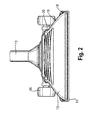
- FIGS. 2 to 5 show a first inventively designed suction nozzle 12 for use on the vacuum cleaner after Fig. 1 , How out Fig. 4 it can be seen, the suction nozzle 12 has a sliding sole 14 with a rectangular suction mouth 15, which extends substantially transversely to the direction of displacement of the suction nozzle and has a width B which is greater by a multiple compared to its length L. In order to ensure that sufficient dust is picked up in the peripheral areas of the suction mouth 15, it is desirable for the width B of the suction mouth 15 to be as uniform as possible.
- the flow channel tapers in the suction nozzle housing 13 from the suction port 15 in the direction of the connecting piece 11 in a funnel shape. It may be concluded from the shape of the funnel-shaped region of the suction nozzle housing 13 shown in frontal, uncut view directly on the shape of the therein flow channel, since this has a substantially uniform wall thickness.
- the funnel-shaped design of the flow channel extends slightly curved, wherein the tangent to the suction-mouth side arc 18 initially runs approximately parallel to the plane of symmetry of the suction nozzle 12. This is spanned by the vertical to the bottom surface and the longitudinal extent of the flow channel and protrudes in the presentation Fig. 2 centrally and vertically out of the suction nozzle 12.
- a region 19 adjoins the bend 18 downstream, in which the funnel tapers substantially linearly, before another, but oppositely curved arc 20 adjoins in the transition region to the connecting piece 11.
- Fig. 3 and 5 show the course of the flow channel in a lateral view.
- the longitudinal extension 21 of the funnel-shaped narrowing cross-section of the flow channel runs in a lateral view in the embodiment of the suction mouth 15 starting arcuately curved and follows over an angle of about 90 ° approximately the course of a circular arc.
- a gentle deflection of the suction air flow whereby the pressure loss is reduced in the pipe bend.
- the free flow cross section in the pipe bend widens slightly, as a result of which the pressure-consuming vortex formation in the suction air flow is further reduced.
- the diameter of the rotatably mounted on the suction nozzle housing 13 wheel assembly 16 is dimensioned so that it protrudes only insignificantly above the suction nozzle housing 13.
- the wheel assembly 16 thus hinders the driving under furniture, it should be noted that the articulated connection piece 11 can be pivoted together with inserted push tube 10 in this process down.
- the axis of rotation 26 of the wheel assembly 16 extends below the flow channel of the suction nozzle housing 13, so that the wheel assembly 16 can be basically equipped with a continuous axis. In the exemplary embodiment, however, the wheels are inserted separately via axle stubs 27 into associated receptacles of the suction nozzle housing 13.
- a further reduction of the pressure loss is surprisingly achieved in that the cross section of the flow channel in a lateral view has regions of different curvature direction. It is provided that the longitudinal extension of the cross section of the flow channel in lateral view from the suction mouth 15 starting first from the connecting piece 11 pioneering in a first arc section 22 to a located below the flow channel first transverse axis 23 and subsequently to the connecting piece 11 indicative in a second arc section 24 to a located above the flow channel transverse axis 25 is curved.
- the height of the suction nozzle 12 can be made so low that a driving under low furniture, such as beds, can be carried out comfortably.
- the pressure loss in the suction mouth-side flow channel of the suction nozzle 12 can be kept low, that the power of the suction fan 5 is used particularly efficiently.
- a uniform pressure distribution over the width of the suction mouth 15 can be achieved.
Landscapes
- Engineering & Computer Science (AREA)
- Mechanical Engineering (AREA)
- Nozzles For Electric Vacuum Cleaners (AREA)
Abstract
Description
- Die Erfindung betrifft eine Saugdüse für einen Staubsauger, mit einem Saugdüsengehäuse, welches einen Strömungskanal zur Strömungsverbindung eines Saugmunds mit einem Sauggebläse ausbildet, wobei sich der Querschnitt des Strömungskanal vom Saugmund ausgehend in frontaler Ansicht trichterförmig verengt. Die Erfindung betrifft ferner einen mit einer derartigen Saugdüse ausgestatteten Staubsauger.
- Staubsauger dienen der Aufnahme von Verschmutzungen von Bodenflächen, Möbeln oder dergleichen durch einen Saugluftstrom. Hierzu wird der Saugmund einer Saugdüse auf die zu reinigende Oberfläche aufgesetzt, so dass Staub oder andere Verschmutzungen vom Saugluftstrom angesaugt werden. Der Saugluftstrom wird durch ein Sauggebläse erzeugt, welches mit einer Staubabscheideeinrichtung, beispielsweise einem Fliehkraftabscheider oder Staubfilterbeutel, in Strömungsverbindung steht. Die von der Saugdüse aufgenommenen Schmutzpartikel werden in der Staubabscheideeinrichtung gesammelt, während die gereinigte Luft an die Umgebung abgegeben wird. Der Saugmund einer für die Bodenreinigung geeigneten Saugdüse weist üblicherweise eine rechteckige Gestalt auf und erstreckt sich quer zur Schieberichtung. Dabei ist es wünschenswert, dass über die gesamte Breite des Saugmunds ein homogener Unterdruck anliegt, um ein gleichmäßiges Saugergebnis zu erzielen. Um die Leistung des Sauggebläses besonders wirksam nutzen zu können, ist ferner ein möglichst geringer Druckverlust zwischen Saugmund und Sauggebläse vorteilhaft.
- Das Sauggebläse und die Staubabscheideeinrichtung können beispielsweise an einem Schubrohr befestigt sein, das unmittelbar mechanisch mit der Saugdüse verbunden ist und in der Regel auch einen Teil des Strömungskanals zwischen Saugdüse und Sauggebläse ausbildet (Stielstaubsauger). Nach einer anderen üblichen Bauform sind Sauggebläse und die Staubabscheideeinrichtung im Gehäuse eines gesonderten Aggregateträgers angeordnet, der mittels eines Fahrwerks über die Bodenfläche bewegt werden kann und mit dem in die Saugdüse eingesteckten Schubrohr durch eine flexible Schlauchleitung strömungsverbunden ist (Kansiterstaubsauger).
- Eine Saugdüse der eingangs genannten Art ist aus der Patentschrift
CH 271904 - In der europäischen Patentanmeldung
EP 0 404 278 A2 wird ein Düsenwerkzeug für eine Nassreinigungsvorrichtung offenbart, dessen Querschnitt sich gleichfalls in frontaler Ansicht trichterförmig verengt. Die Längsachse dieses Querschnitts ist saugmundseitig gerade ausgebildet, jedoch gegenüber der Vertikalen um einen Winkel von etwa 20° geneigt, wobei der nachfolgende Anschlussstutzen erneut aus der Spitze des Trichters abknickt. Auch diese Ausführung kann strömungstechnisch ungünstig sein. - Der Erfindung liegt die Aufgabe zugrunde, eine verbesserte Saugdüse und einen verbesserten Staubsauger bereitzustellen. Insbesondere sollen gattungsgemäße Saugdüsen und Staubsauger so weitergebildet werden, dass die Staubaufnahme verbessert, der Druckverlust gering gehalten und ein gutes Saugverhalten auch in den seitlichen Endbereichen des Saugmunds erzielt wird. Darüber hinaus soll die Bauhöhe der Düse so bemessen sein, dass ein Unterfahren von Möbeln oder dergleichen möglichst wenig behindert wird.
- Die Bezugszeichen in sämtlichen Ansprüchen haben keine einschränkende Wirkung, sondern sollen lediglich deren Lesbarkeit verbessern.
- Die der Erfindung zugrunde liegende Aufgabe wird bei einer Saugdüse der eingangs genannten Art dadurch gelöst, dass die Längserstreckung des sich trichterförmig verengenden Querschnitts des Strömungskanals im Saugdüsengehäuse in seitlicher Ansicht vom Saugmund ausgehend wenigstens in einem Abschnitt bogenförmig gekrümmt verläuft. Ein solcher Strömungskanal kann insbesondere entlang eines Längsschnitts des Kanals senkrecht zur Längserstreckung des Saugmunds wenigstens in einem Abschnitt bogenförmig gekrümmt sein. Nachfolgend kann der Strömungskanal in den Anschlussstutzen für das Schubrohr einmünden, welcher üblicherweise gelenkig mit dem übrigen Teil der Saugdüse verbunden ist.
- Die Aufgabe wird ferner durch einen mit einer derartigen Saugdüse ausgestatteten Staubsauger gelöst. der Staubsauger ist vorzugsweise ein Stilstaubsauger.
- Im Sinne der vorliegenden Erfindung ist die Längserstreckung die Erstreckung des Strömungskanals in Strömungsrichtung. Der Querschnitt des Strömungskanals ist dessen Querschnittsfläche senkrecht zur Längserstreckung des Kanals. Begriffe wie frontal, seitlich, oberhalb, unterhalb u.s.w. sind im Sinne der vorliegenden Erfindung immer in Bezug auf die vorgesehene Gebrauchslage der Saugdüse zu verstehen.
- Es ist ein erreichbarer Vorteil der Erfindung, dass die Bauhöhe einer derartigen Saugdüse so gering ausgebildet werden kann, dass ein Unterfahren auch niedriger Möbel, beispielsweise von Betten, komfortabel durchgeführt werden kann. Die Erfinder haben festgestellt, dass sich außerdem trotz der Krümmung eine gleichmäßige Druckverteilung über die Breite des Saugmunds erzielen lässt. Auch ist erreichbar, dass der Druckverlust im saugmundseitigen Strömungskanal der Saugdüse relativ gering ausfällt, so dass die Leistung des Sauggebläses besonders effizient genutzt wird.
- Vorteilhafte Aus- oder Weiterbildungen, welche einzeln oder in Kombination miteinander eingesetzt werden können, sind Gegenstand der abhängigen Ansprüche.
- Nach einer ersten bevorzugten Ausführung der Erfindung verläuft die Krümmung des Querschnitts des Strömungskanals entlang eines kreisförmigen oder elliptischen Bogens. Eine derartige Kontur ist fertigungstechnisch besonders einfach herstellbar und erfordert aufgrund ihrer kompakten Gestalt einen relativ geringen Werkstoffaufwand.
- Dabei ist es weiterhin von Vorteil, wenn sich der Bogen über einen Winkel von 45° oder mehr, besonders vorzugsweise von 70° oder mehr erstreckt. Vorzugsweise erstreckt sich der Bogen über einen Winkel von 135° oder weniger, besonders vorzugsweise 120° oder weniger. Ein besonders bevorzugter Bogen erstrecks sich über einen Winkel von ca. 90°. Diese Ausführung der Erfindung hat insbesondere den Vorteil, dass ein Anschlussstutzen mit geringem Aufwand so gelenkig an das Saugdüsengehäuse angebundenen werden kann, dass er ohne Schwierigkeiten auch horizontal ausgerichtet werden kann. Dadurch kann vorteilhafterweise ein in den Anschlussstutzen eingeschobene Schubrohr zum Unterfahren von Möbeln komfortabel in eine horizontale Position verlagert werden.
- Nach einer anderen Ausführung der Erfindung ist bevorzugt, dass der Querschnitt des Strömungskanals in seitlicher Ansicht Bereiche unterschiedlicher Krümmungsrichtung aufweist. Dabei ist es insbesondere von Vorteil, dass die Längserstreckung des Querschnitts des Strömungskanals in seitlicher Ansicht vom Saugmund ausgehend zunächst in einem ersten Bogenabschnitt um eine unterhalb des Strömungskanals befindliche Querachse und nachfolgend in einem zweiten Bogenabschnitt um eine oberhalb des Strömungskanals befindliche Querachse gekrümmt verläuft. Auch wenn sich der Strömungskanal bei dieser Ausbildung etwas verlängert, ist der Druckverlust in einem solchen bionischen Rohrbogen überraschenderweise geringer als in einem nur in eine Richtung gekrümmten Kanal. Eine Querachse ist dabei eine Achse, die bei Gewöhnlichem Gebrauch des Staubsaugers senkrecht zur Längserstreckung des Strömungskanals und parallel zum zu reinigenden Boden verläuft.
- Besonders wirksam ist diese Ausbildung dann, wenn sich der zweite Bogenabschnitt über einen Winkel von 5° oder mehr erstreckt, besonders vorzugsweise 7°ôder mehr. Er erstreckt sich vorzugsweise über 30° oder weniger, besonders vorzugsweise über 20° oder weniger. Dabei erstreckt sich der erste Bogenabschnitt mit Vorteil zum nachfolgenden Ausgleich des zunächst vom Anschlussstutzen wegweisenden Strömungskanals über einen Winkel von vorzugsweise mehr 95° oder mehr und besonders vorzugsweise 110° oder weniger.
- Zum Unterfahren von Möbeln hat es sich als besonders günstig erwiesen, dass der vertikale Durchmesser der gekrümmten Längserstreckung in seitlicher Ansicht weniger als 12,5 cm, vorzugsweise weniger als 10 cm und insbesondere rund 7,5 cm beträgt. Die Saugdüse baut hierdurch besonders kompakt, ohne dass bei einer erfindungsgemäßen Ausbildung des Strömungskanals eine Beeinträchtigung der Funktion erfolgt.
- Weiterhin ist es für die Handhabung des Staubsaugers von Vorteil, wenn die Saugdüse mit einem Fahrwerk in Form einer Räderanordnung ausgestattet ist, welche nach oben nicht oder nur unwesentlich über das Saugdüsengehäuse herausragt und somit das Unterfahren von Möbeln nicht behindern. Durch das Fahrwerk wird die Gleitsohle der Saugdüse insbesondere bei einem Stielstaubsauger entlastet, wodurch bei der Reinigung nachgiebiger Bodenbeläge eine Verringerung der Verschiebekräfte erzielt werden kann. Besonders vorteilhaft ist in diesem Fall, dass die Drehachse der Räderanordnung unterhalb des Strömungskanals der Saugdüse angeordnet ist. Durch diese Ausbildung können die Räder an einer durchgängigen Achse drehbar befestigt werden, ohne dass diese die Strömung im Saugkanal beeinträchtigt. Bevorzugt ist ferner, dass die äußeren Axialflächen der Räder mit elastischen Schutzkappen versehen sind, so dass ein seitlicher Kontakt der Räder empfindliche Oberflächen an Möbeln nicht beschädigt. Mit besonderem Vorteil ist das Zentrum der dünnwandigen Schutzkappen dabei nach außen vorgewölbt ausgebildet, so dass es bei einem Kontakt mit Möbelstücken nach innen einfedern kann.
- Der bevorzugte Raddurchmesser ist größer als 20 mm, vorzugsweise größer als 40 mm, besonders vorzugsweise größer als 50 mm. Der bevorzugte Raddurchmesser ist kleiner als 90 mm, vorzugsweise kleiner als 80 mm, besonders vorzugsweise kleiner als 70 mm, z.B. ca. 60 mm. Dadurch ist vorteilhaft erreichbar, dass die Räder möglichst wenig in einen nachgiebigen Untergrund einsinken, andererseits die Räder nicht so groß sind, dass sie das Unterfahren von Möbelstücken behindern. Die Laufflächen benachbarter, in Verschieberichtung beabstandeter Räder liegen vorzugsweise weniger als 40 mm auseinander, besonders vorzugsweise weniger als 20 mm, besonders vorzugsweise weniger als 10 mm. Sie liegen vorzugsweise mehr als 1 mm auseinander, vorzugsweise mehr als 3 mm, z.B. 5 mm. Dies erlaubt einerseits eine kompakte Bauweise, andererseits verhindert es, dass sich größere Schmutzpartikel zwischen den Rädern verkeilen und die Räder dadurch blockieren.
- Weiterhin ist es für die Vergleichmäßigung der Druckverteilung über die Breite des Saugmunds von Vorteil, wenn der sich in frontaler Ansicht trichterförmig verengende Querschnitt des Strömungskanals geschwungen verläuft. Dabei wird eine besonders günstige Druckverteilung dann erreicht, wenn die Tangente an den Querschnitt des Strömungskanals in frontaler Ansicht saugmundseitig wie im Übergang zum Saugstutzen parallel zur Symmetrieebene der Saugdüse verläuft. Die Symmetrieebene der Saugdüse wird üblicherweise durch die Vertikale und die Längserstreckung des Strömungskanals aufgespannt.
- Weiterhin ist es strömungstechnisch günstig, wenn sich der freie Strömungsquerschnitt in der Saugdüse vom Saugmund aus bis zum Eintritt in einen Anschlussstutzen für das Schubrohr fortlaufend erweitert. Diese Ausbildung hat die Wirkung eines Diffusors und verringert die druckmindernde Wirbelbildung im Strömungskanal.
- Mit der Erfindung kann die Bauhöhe der Saugdüse vorteilhafterweise so gering ausgebildet werden, dass ein Unterfahren auch niedriger Möbel, beispielsweise von Betten, komfortabel durchgeführt werden kann. Gleichzeitig kann der Druckverlust im saugmundseitigen Strömungskanal der Saugdüse gering gehalten und eine gleichmäßige Druckverteilung über die Breite des Saugmunds erzielt werden.
- Die Erfindung wird im Folgenden anhand schematischer Zeichnungen an zwei Ausführungsbeispielen mit weiteren Einzelheiten näher erläutert.
- Es zeigen:
- Fig. 1:
- die Darstellung eines erfindungsgemäß ausgestatteten Kansiterstaubsaugers;
- Fig. 2:
- eine frontale Ansicht einer ersten erfindungsgemäß ausgebildeten Saugdüse;
- Fig. 3:
- die Saugdüse nach
Fig. 2 in einer seitlichen, perspektivischen Ansicht; - Fig. 4:
- die Saugdüse nach
Fig. 2 und3 in einer Ansicht von unten; - Fig. 5:
- die gleiche Saugdüse in einem Längsschnitt;
und schließlich - Fig. 6:
- einen Längsschnitt durch eine andere erfindungsgemäß ausgebildete Saugdüse.
- Der in
Fig. 1 dargestellte Staubsauger 1 ist als Kansiterstaubsauger ausgebildet. Grundsätzlich ist die Erfindung jedoch auch bei anderen Bauformen, beispielsweise einem Stielstaubsauger, mit Vorteil einsetzbar. Alle Richtungs- und Ortsangaben beziehen sich auf eine Saugdüse, welche auf einer horizontalen Fläche aufliegt und in Vorwärtsrichtung, also in horizontaler Richtung entgegen der Längserstreckung eines mit der Saugdüse verbundenen Saugrohrs, bewegt wird. - Der Staubsauger 1 nach
Fig. 1 besteht aus einem gesonderten Aggregateträger 2, welcher mit einem Fahrwerk 3 ausgestattet ist und damit komfortabel über die zu reinigende Bodenfläche bewegt werden kann. Das Gehäuse 4 des Aggregateträgers 2 nimmt insbesondere ein Sauggebläse 5 und eine Staubabscheideeinrichtung 6 in Form eines Staubfilterbeutels 7 auf. Weitere, nicht gezeigt Komponenten des Aggregateträgers sind beispielsweise ein aufwickelbares Stromkabel zur elektrischen Verbindung mit einem Stromnetz, Stelleinrichtungen zum Einschalten und zur Leistungseinstellung, elektronische Regelungseinrichtungen und ein Staufach für Zubehör wie Saugbürsten oder dergleichen. - Stromauf der Staubabscheideeinrichtung 6 ist ein Anschluss 8 zum Anbringen eines biegsamen Saugschlauches 9 vorgesehen, welcher seinerseits mit einem telekopierbaren Schubrohr 10 strömungsverbunden ist. Das Schubrohr 10 ist gedichtet in einen Anschlussstutzen 11 der Saugdüse 12 eingeschoben. Stromauf des gelenkig mit der übrigen Saugdüse 12 verbundenen Anschlussstutzens 11 weist die Saugdüse 12 ferner ein Saugdüsengehäuse 13 und eine über die zu reinigende Bodenfläche zu führende Gleitsohle 14 mit einem Saugmund 15 auf. Die Saugdüse 12 weist ferner eine Räderanordnung 16 zur Abstützung des Schubrohrs 10 auf.
- Beim Reinigungsvorgang liegt die Gleitsohle 14 dichtend an der Bodenfläche an, wobei durch den am Saugmund 15 anliegenden Unterdruck ein Luftstrom angesaugt wird und den auf der Bodenfläche befindlichen Staub mitführt. Der Schmutz führende Luftstrom wird durch das Schubrohr 10 und den Saugschlauch 9 in die Staubabscheideeinrichtung 6 geleitet, wo der Staub im Staubfilterbeutel 7 abgeschieden wird. Der nunmehr gereinigte Luftstrom durchquert das Sauggebläse 5 und wird anschließend durch eine Öffnung 17 im Gehäuse 4 des Aggregateträgers 2 in die Umgebung abgeführt.
- Die
Figuren 2 bis 5 zeigen eine erste erfindungsgemäß ausgebildete Saugdüse 12 zur Verwendung an dem Staubsauger nachFig. 1 . Wie ausFig. 4 ersichtlich, weist die Saugdüse 12 eine Gleitsohle 14 mit einem rechteckigen Saugmund 15 auf, der sich im Wesentlichen quer zur Verschieberichtung der Saugdüse erstreckt und eine gegenüber seiner Länge L um ein Vielfaches größere Breite B besitzt. Damit auch in den Randbereichen des Saugmunds 15 eine ausreichende Staubaufnahme erfolgt, ist es wünschenswert, dass über die Breite B des Saugmunds 15 ein möglichst gleichmäßiger Unterdruck anliegt. - Wie in
Fig. 2 erkennbar, verjüngt sich der Strömungskanal im Saugdüsengehäuse 13 vom Saugmund 15 aus in Richtung des Anschlussstutzens 11 trichterförmig. Dabei darf aus der Gestalt des in frontaler, ungeschnittener Ansicht gezeigten trichterförmigen Bereichs des Saugdüsengehäuses 13 unmittelbar auf die Gestalt des darin befindlichen Strömungskanals geschlossen werden, da dieses eine im Wesentlichen gleichmäßige Wanddicke aufweist. Die trichterförmige Ausbildung des Strömungskanals verläuft dabei leicht geschwungen, wobei die Tangente an den saugmundseitigen Bogen 18 zunächst näherungsweise parallel zu der Symmetrieebene der Saugdüse 12 verläuft. Diese wird durch die Vertikale zur Bodenfläche und die Längserstreckung des Strömungskanals aufgespannt und ragt bei der Darstellung nachFig. 2 mittig und senkrecht aus der Saugdüse 12 hervor. An den Bogen 18 schließt sich stromab ein Bereich 19 an, in welchem sich der Trichter im Wesentlichen linear verjüngt, bevor sich im Übergangsbereich zum Anschlussstutzen 11 ein weiterer, aber gegensinnig gekrümmter Bogen 20 anschließt. Durch diese Ausbildung wird randseitig ein sanfter Strömungsübergang vom Saugmund 15 zum Anschlussstutzen 11 erzielt. -
Fig. 3 und5 zeigen den Verlauf des Strömungskanals in seitlicher Ansicht. Die Längserstreckung 21 des sich trichterförmig verengenden Querschnitts des Strömungskanals verläuft in seitlicher Ansicht im Ausführungsbeispiels vom Saugmund 15 ausgehend bogenförmig gekrümmt und folgt über einen Winkel von etwa 90 ° näherungsweise dem Verlauf eines Kreisbogens. Somit erfolgt auch in dieser Richtung eine sanfte Umlenkung des Saugluftstroms, wodurch der Druckverlust im Rohrbogen reduziert wird. Gleichzeitig erweitert sich der freie Strömungsquerschnitt im Rohrbogen leicht, wodurch die druckverbrauchende Wirbelbildung im Saugluftstrom weiter verringert wird. - Der Durchmesser der am Saugdüsengehäuse 13 drehbar gelagerten Räderanordnung 16 ist so bemessen, dass diese nach oben nur unwesentlich über das Saugdüsengehäuse 13 herausragt. Die Räderanordnung 16 behindert das Unterfahren von Möbeln somit nicht, wobei zu beachten ist, dass der gelenkig angebundene Anschlussstutzen 11 samt eingestecktem Schubrohr 10 bei diesem Vorgang nach unten verschwenkt werden kann. Die Drehachse 26 der Räderanordnung 16 verläuft unterhalb des Strömungskanals des Saugdüsengehäuses 13, so dass die Räderanordnung 16 grundsätzlich mit einer durchgehenden Achse ausgestattet werden kann. Im Ausführungsbeispiels sind die Räder allerdings gesondert über Achsstummel 27 in zugehörige Aufnahmen des Saugdüsengehäuses 13 eingefügt.
- Bei dem in
Fig. 6 im Längsschnitt gezeigten Rohrbogen zwischen Saugmund 15 und Anschlussstutzen 11 wird eine weitere Verringerung des Druckverlustes überraschenderweise dadurch erzielt, dass der Querschnitt des Strömungskanals in seitlicher Ansicht Bereiche unterschiedlicher Krümmungsrichtung aufweist. Dabei ist vorgesehen, dass die Längserstreckung des Querschnitts des Strömungskanals in seitlicher Ansicht vom Saugmund 15 ausgehend zunächst vom Anschlussstutzen 11 wegweisend in einem ersten Bogenabschnitt 22 um eine unterhalb des Strömungskanals befindliche erste Querachse 23 und nachfolgend zum Anschlussstutzen 11 hinweisend in einem zweiten Bogenabschnitt 24 um eine oberhalb des Strömungskanals befindliche Querachse 25 gekrümmt verläuft. - Überraschenderweise sinkt der Druckverlust durch diesen meanderförmigen Verlauf des Strömungskanals gegenüber einem kreisbogenförmigen Rohrbogen ab, ohne dass diese Bauform hinsichtlich ihrer Bauhöhe mit nennenswerten Nachteilen verbunden ist.
- Durch die bogenförmige Krümmung kann die Bauhöhe der Saugdüse 12 so gering ausgebildet werden, dass ein Unterfahren auch niedriger Möbel, beispielsweise von Betten, sich komfortabel durchführen lässt. Dabei kann der Druckverlust im saugmundseitigen Strömungskanal der Saugdüse 12 gering gehalten werden, dass die Leistung des Sauggebläses 5 besonders effizient genutzt wird. Auch lässt sich eine gleichmäßige Druckverteilung über die Breite des Saugmunds 15 erzielen.
- Die in der vorstehenden Beschreibung, den Ansprüchen und den Zeichnungen offenbarten Merkmale können sowohl einzeln als auch in beliebiger Kombination für die Verwirklichung der Erfindung in ihren verschiedenen Ausgestaltungen von Bedeutung sein.
-
- 1
- Staubsauger
- 2
- Aggregateträger
- 3
- Fahrwerk
- 4
- Gehäuse
- 5
- Sauggebläse
- 6
- Staubabscheideeinrichtung
- 7
- Staubfilterbeutel
- 8
- Anschluss
- 9
- Saugschlauch
- 10
- Schubrohr
- 11
- Anschlussstutzen
- 12
- Saugdüse
- 13
- Saugdüsengehäuse
- 14
- Gleitsohle
- 15
- Saugmund
- 16
- Räderanordnung
- 17
- Öffnung
- 18
- Bogen
- 19
- Bereich
- 20
- Bogen
- 21
- Längserstreckung
- 22
- (erster) Bogenabschnitt
- 23
- (erste) Querachse
- 24
- (zweiter) Bogenabschnitt
- 25
- (zweite) Querachse
- 26
- Drehachse (der Räderanordnung)
- 27
- Achsstummel
- B
- Breite (des Saugmunds)
- L
- Länge (des Saugmunds)
Claims (14)
- Saugdüse (12) für einen Staubsauger, mit einem Saugdüsengehäuse (13), welches einen Strömungskanal zur Strömungsverbindung eines Saugmunds (15) mit einem Sauggebläse (5) ausbildet, wobei sich der Querschnitt des Strömungskanals vom Saugmund (15) ausgehend in frontaler Ansicht trichterförmig verengt, dadurch gekennzeichnet, dass die Längserstreckung (21) des sich trichterförmig verengenden Querschnitts des Strömungskanals im Saugdüsengehäuse (13) in seitlicher Ansicht vom Saugmund (15) ausgehend wenigstens in einem Abschnitt bogenförmig gekrümmt verläuft.
- Saugdüse nach Anspruch 1, dadurch gekennzeichnet, dass die Krümmung des Querschnitts des Strömungskanals entlang eines kreisförmigen oder elliptischen Bogens verläuft.
- Saugdüse nach Anspruch 2, dadurch gekennzeichnet, dass der Bogen sich über einen Winkel von 70° bis vorzugsweise 90° erstreckt.
- Saugdüse nach Anspruch 1, dadurch gekennzeichnet, dass der Querschnitt des Strömungskanals in seitlicher Ansicht Bereiche unterschiedlicher Krümmungsrichtung aufweist.
- Saugdüse nach Anspruch 4, dadurch gekennzeichnet, dass die Längserstreckung (21) des Strömungskanals in seitlicher Ansicht vom Saugmund (15) ausgehend zunächst in einem ersten Bogenabschnitt (22) um eine unterhalb des Strömungskanals befindliche erste Querachse (23) und nachfolgend in einem zweiten Bogenabschnitt (24) um eine oberhalb des Strömungskanals befindliche zweite Querachse (25) gekrümmt verläuft.
- Saugdüse nach Anspruch 5, dadurch gekennzeichnet, dass sich der zweite Bogenabschnitt (22) über einen Winkel von 5° bis 20° erstreckt.
- Saugdüse nach Anspruch 5 oder 6, dadurch gekennzeichnet, dass sich der erste Bogenabschnitt (24) über einen Winkel von 95° bis 110° erstreckt.
- Saugdüse nach einem der vorhergehenden Ansprüche, dadurch gekennzeichnet, dass der vertikale Durchmesser der gekrümmten Längserstreckung (21) in seitlicher Ansicht weniger als 12,5 cm, vorzugsweise weniger als 10 cm und insbesondere rund 7,5 cm beträgt.
- Saugdüse nach einem der vorhergehenden Ansprüche, dadurch gekennzeichnet, dass die Saugdüse (12) mit einer Räderanordnung (16) ausgestattet ist, welche nach oben nicht oder nur unwesentlich über das Saugdüsengehäuse (13) herausragt.
- Saugdüse nach Anspruch 9, dadurch gekennzeichnet, dass die Drehachse (26) der Räderanordnung (16) unterhalb des Strömungskanals der Saugdüse (12) angeordnet ist.
- Saugdüse nach einem der vorhergehenden Ansprüche, dadurch gekennzeichnet, dass der sich in frontaler Ansicht trichterförmig verengende Querschnitt des Strömungskanals geschwungen verläuft.
- Saugdüse nach Anspruch 11, dadurch gekennzeichnet, dass die Tangente an den Querschnitt des Strömungskanals in frontaler Ansicht saugmundseitig wie im Übergang zum Saugstutzen (11) parallel zur Symmetrieebene der Saugdüse (12) verläuft.
- Saugdüse nach einem der vorhergehenden Ansprüche, dadurch gekennzeichnet, dass sich der freie Strömungsquerschnitt in der Saugdüse (12) vom Saugmund (15) aus bis zum Eintritt in einen Anschlussstutzen (11) für das Schubrohr (10) fortlaufend verengt.
- Staubsauger (1) mit einer Saugdüse nach einem der vorhergehenden Ansprüche.
Applications Claiming Priority (1)
| Application Number | Priority Date | Filing Date | Title |
|---|---|---|---|
| DE102011077277A DE102011077277A1 (de) | 2011-06-09 | 2011-06-09 | Saugdüse und Staubsauger |
Publications (3)
| Publication Number | Publication Date |
|---|---|
| EP2532292A2 true EP2532292A2 (de) | 2012-12-12 |
| EP2532292A3 EP2532292A3 (de) | 2017-08-23 |
| EP2532292B1 EP2532292B1 (de) | 2021-12-15 |
Family
ID=46318866
Family Applications (1)
| Application Number | Title | Priority Date | Filing Date |
|---|---|---|---|
| EP12170186.6A Not-in-force EP2532292B1 (de) | 2011-06-09 | 2012-05-31 | Saugdüse und Staubsauger |
Country Status (2)
| Country | Link |
|---|---|
| EP (1) | EP2532292B1 (de) |
| DE (1) | DE102011077277A1 (de) |
Citations (1)
| Publication number | Priority date | Publication date | Assignee | Title |
|---|---|---|---|---|
| CH271904A (de) | 1947-05-17 | 1950-11-30 | Electrolux Ab | Staubsaugermundstück. |
Family Cites Families (8)
| Publication number | Priority date | Publication date | Assignee | Title |
|---|---|---|---|---|
| US1519868A (en) * | 1918-03-04 | 1924-12-16 | American Radiator Co | Suction cleaning apparatus |
| US1951316A (en) * | 1931-10-02 | 1934-03-13 | Allen Sherman Hoff Co | Vacuum cleaner nozzle |
| DE2918759C3 (de) * | 1979-05-09 | 1982-01-07 | Ing. Alfred Schmidt Gmbh, 7822 St Blasien | Vorrichtung zur Aufnahme von Kehrgut mittels eines Saugluftstroms |
| DE3486370T2 (de) | 1984-03-02 | 1995-06-14 | Trc Acquisition Corp | Vorrichtung mit abnehmbarem Behälter für Reinigungsgerät. |
| DE19706240A1 (de) * | 1997-02-18 | 1998-08-20 | Fedag Romanshorn Fa | Saugreinigungswerkzeug mit höhenverstellbarem Saugmund |
| US7254864B2 (en) * | 2004-07-01 | 2007-08-14 | Royal Appliance Mfg. Co. | Hard floor cleaner |
| SE532299C2 (sv) * | 2008-04-17 | 2009-12-08 | Electrolux Ab | Dammsugarmunstycke |
| US8312594B2 (en) * | 2008-06-27 | 2012-11-20 | Nilfisk-Advance, Inc. | Carpet cleaning wand having uniform air flow distribution |
-
2011
- 2011-06-09 DE DE102011077277A patent/DE102011077277A1/de not_active Ceased
-
2012
- 2012-05-31 EP EP12170186.6A patent/EP2532292B1/de not_active Not-in-force
Patent Citations (1)
| Publication number | Priority date | Publication date | Assignee | Title |
|---|---|---|---|---|
| CH271904A (de) | 1947-05-17 | 1950-11-30 | Electrolux Ab | Staubsaugermundstück. |
Also Published As
| Publication number | Publication date |
|---|---|
| EP2532292A3 (de) | 2017-08-23 |
| DE102011077277A1 (de) | 2012-12-13 |
| EP2532292B1 (de) | 2021-12-15 |
Similar Documents
| Publication | Publication Date | Title |
|---|---|---|
| DE60204753T2 (de) | Wasserabstossender kotflügel für kraftfahrzeuge und dergleichen | |
| EP3185741B1 (de) | Saugdüse und hartflächenabsauggerät | |
| DE202011108345U1 (de) | Staubsaugersaugeinrichtung | |
| EP2449934A2 (de) | Saugdüsenanordnung für einen Bodenstaubsauger | |
| DE102013021277A1 (de) | Tragbares Hartflächenabsauggerät | |
| EP2587977B1 (de) | Staubsaugerdüse | |
| EP2531087A1 (de) | Handreiniger für glatte flächen | |
| DE102021203242B4 (de) | Schmutzabscheider für einen Staubsauger | |
| EP2532292B1 (de) | Saugdüse und Staubsauger | |
| DE102015105060B4 (de) | Reinigungsgerät, insbesondere Staubsauger oder Vorsatzgerät eines Staubsaugers | |
| DE102012112532A1 (de) | Upright-Staubsauger | |
| DE4412988B4 (de) | Düse für einen Staubsauger | |
| EP1714734B1 (de) | Staubabsaugeinrichtung zur lösbaren Anbringung an einem Werkzeuggerät, mit schiebenden Ansaugbereich | |
| DE102023108163A1 (de) | Unterwasserreiniger | |
| DE102019125704A1 (de) | Auswechselbarer Akkumulator | |
| DE102011077265B4 (de) | Saugdüse und Staubsauger | |
| DE102011077275B4 (de) | Saugdüse mit Balgen | |
| EP3741276A1 (de) | Staubsauger zur reinigung von bodenflächen | |
| EP2659820B1 (de) | Filterkassette für einen Staubsauger | |
| WO2013144209A1 (de) | Staubfangvorrichtung für staubsauger | |
| DE102019106215A1 (de) | Vorsatzgerät für einen Staubsauger und Verfahren zum Ableiten einer elektrischen Aufladung bei Nutzung eines Staubsaugers mit einem Vorsatzgerät | |
| DE2647504C3 (de) | Saugmäherkopf für einen Schlegelgrasmäher | |
| EP3298944B1 (de) | Bodendüse für staubsauger und staubsauger | |
| DE2914450B1 (de) | Staubsammelbehaelter fuer Schleifboecke | |
| DE202004021148U1 (de) | Staubsauger-Saugvorrichtung |
Legal Events
| Date | Code | Title | Description |
|---|---|---|---|
| PUAI | Public reference made under article 153(3) epc to a published international application that has entered the european phase |
Free format text: ORIGINAL CODE: 0009012 |
|
| AK | Designated contracting states |
Kind code of ref document: A2 Designated state(s): AL AT BE BG CH CY CZ DE DK EE ES FI FR GB GR HR HU IE IS IT LI LT LU LV MC MK MT NL NO PL PT RO RS SE SI SK SM TR |
|
| AX | Request for extension of the european patent |
Extension state: BA ME |
|
| RAP1 | Party data changed (applicant data changed or rights of an application transferred) |
Owner name: BSH HAUSGERAETE GMBH |
|
| RIC1 | Information provided on ipc code assigned before grant |
Ipc: A47L 9/02 20060101AFI20170505BHEP |
|
| PUAL | Search report despatched |
Free format text: ORIGINAL CODE: 0009013 |
|
| AK | Designated contracting states |
Kind code of ref document: A3 Designated state(s): AL AT BE BG CH CY CZ DE DK EE ES FI FR GB GR HR HU IE IS IT LI LT LU LV MC MK MT NL NO PL PT RO RS SE SI SK SM TR |
|
| AX | Request for extension of the european patent |
Extension state: BA ME |
|
| RIC1 | Information provided on ipc code assigned before grant |
Ipc: A47L 9/02 20060101AFI20170720BHEP |
|
| STAA | Information on the status of an ep patent application or granted ep patent |
Free format text: STATUS: REQUEST FOR EXAMINATION WAS MADE |
|
| 17P | Request for examination filed |
Effective date: 20180223 |
|
| RBV | Designated contracting states (corrected) |
Designated state(s): AL AT BE BG CH CY CZ DE DK EE ES FI FR GB GR HR HU IE IS IT LI LT LU LV MC MK MT NL NO PL PT RO RS SE SI SK SM TR |
|
| STAA | Information on the status of an ep patent application or granted ep patent |
Free format text: STATUS: EXAMINATION IS IN PROGRESS |
|
| 17Q | First examination report despatched |
Effective date: 20200903 |
|
| GRAP | Despatch of communication of intention to grant a patent |
Free format text: ORIGINAL CODE: EPIDOSNIGR1 |
|
| STAA | Information on the status of an ep patent application or granted ep patent |
Free format text: STATUS: GRANT OF PATENT IS INTENDED |
|
| INTG | Intention to grant announced |
Effective date: 20210526 |
|
| GRAJ | Information related to disapproval of communication of intention to grant by the applicant or resumption of examination proceedings by the epo deleted |
Free format text: ORIGINAL CODE: EPIDOSDIGR1 |
|
| STAA | Information on the status of an ep patent application or granted ep patent |
Free format text: STATUS: EXAMINATION IS IN PROGRESS |
|
| GRAP | Despatch of communication of intention to grant a patent |
Free format text: ORIGINAL CODE: EPIDOSNIGR1 |
|
| STAA | Information on the status of an ep patent application or granted ep patent |
Free format text: STATUS: GRANT OF PATENT IS INTENDED |
|
| INTC | Intention to grant announced (deleted) | ||
| GRAJ | Information related to disapproval of communication of intention to grant by the applicant or resumption of examination proceedings by the epo deleted |
Free format text: ORIGINAL CODE: EPIDOSDIGR1 |
|
| GRAP | Despatch of communication of intention to grant a patent |
Free format text: ORIGINAL CODE: EPIDOSNIGR1 |
|
| GRAS | Grant fee paid |
Free format text: ORIGINAL CODE: EPIDOSNIGR3 |
|
| INTG | Intention to grant announced |
Effective date: 20211012 |
|
| GRAA | (expected) grant |
Free format text: ORIGINAL CODE: 0009210 |
|
| STAA | Information on the status of an ep patent application or granted ep patent |
Free format text: STATUS: THE PATENT HAS BEEN GRANTED |
|
| INTG | Intention to grant announced |
Effective date: 20211026 |
|
| AK | Designated contracting states |
Kind code of ref document: B1 Designated state(s): AL AT BE BG CH CY CZ DE DK EE ES FI FR GB GR HR HU IE IS IT LI LT LU LV MC MK MT NL NO PL PT RO RS SE SI SK SM TR |
|
| REG | Reference to a national code |
Ref country code: GB Ref legal event code: FG4D Free format text: NOT ENGLISH Ref country code: CH Ref legal event code: EP |
|
| REG | Reference to a national code |
Ref country code: IE Ref legal event code: FG4D Free format text: LANGUAGE OF EP DOCUMENT: GERMAN Ref country code: DE Ref legal event code: R096 Ref document number: 502012016957 Country of ref document: DE |
|
| REG | Reference to a national code |
Ref country code: AT Ref legal event code: REF Ref document number: 1454838 Country of ref document: AT Kind code of ref document: T Effective date: 20220115 |
|
| REG | Reference to a national code |
Ref country code: LT Ref legal event code: MG9D |
|
| REG | Reference to a national code |
Ref country code: NL Ref legal event code: MP Effective date: 20211215 |
|
| PG25 | Lapsed in a contracting state [announced via postgrant information from national office to epo] |
Ref country code: RS Free format text: LAPSE BECAUSE OF FAILURE TO SUBMIT A TRANSLATION OF THE DESCRIPTION OR TO PAY THE FEE WITHIN THE PRESCRIBED TIME-LIMIT Effective date: 20211215 Ref country code: LT Free format text: LAPSE BECAUSE OF FAILURE TO SUBMIT A TRANSLATION OF THE DESCRIPTION OR TO PAY THE FEE WITHIN THE PRESCRIBED TIME-LIMIT Effective date: 20211215 Ref country code: FI Free format text: LAPSE BECAUSE OF FAILURE TO SUBMIT A TRANSLATION OF THE DESCRIPTION OR TO PAY THE FEE WITHIN THE PRESCRIBED TIME-LIMIT Effective date: 20211215 Ref country code: BG Free format text: LAPSE BECAUSE OF FAILURE TO SUBMIT A TRANSLATION OF THE DESCRIPTION OR TO PAY THE FEE WITHIN THE PRESCRIBED TIME-LIMIT Effective date: 20220315 |
|
| PG25 | Lapsed in a contracting state [announced via postgrant information from national office to epo] |
Ref country code: SE Free format text: LAPSE BECAUSE OF FAILURE TO SUBMIT A TRANSLATION OF THE DESCRIPTION OR TO PAY THE FEE WITHIN THE PRESCRIBED TIME-LIMIT Effective date: 20211215 Ref country code: NO Free format text: LAPSE BECAUSE OF FAILURE TO SUBMIT A TRANSLATION OF THE DESCRIPTION OR TO PAY THE FEE WITHIN THE PRESCRIBED TIME-LIMIT Effective date: 20220315 Ref country code: LV Free format text: LAPSE BECAUSE OF FAILURE TO SUBMIT A TRANSLATION OF THE DESCRIPTION OR TO PAY THE FEE WITHIN THE PRESCRIBED TIME-LIMIT Effective date: 20211215 Ref country code: HR Free format text: LAPSE BECAUSE OF FAILURE TO SUBMIT A TRANSLATION OF THE DESCRIPTION OR TO PAY THE FEE WITHIN THE PRESCRIBED TIME-LIMIT Effective date: 20211215 Ref country code: GR Free format text: LAPSE BECAUSE OF FAILURE TO SUBMIT A TRANSLATION OF THE DESCRIPTION OR TO PAY THE FEE WITHIN THE PRESCRIBED TIME-LIMIT Effective date: 20220316 |
|
| PG25 | Lapsed in a contracting state [announced via postgrant information from national office to epo] |
Ref country code: NL Free format text: LAPSE BECAUSE OF FAILURE TO SUBMIT A TRANSLATION OF THE DESCRIPTION OR TO PAY THE FEE WITHIN THE PRESCRIBED TIME-LIMIT Effective date: 20211215 |
|
| PG25 | Lapsed in a contracting state [announced via postgrant information from national office to epo] |
Ref country code: SM Free format text: LAPSE BECAUSE OF FAILURE TO SUBMIT A TRANSLATION OF THE DESCRIPTION OR TO PAY THE FEE WITHIN THE PRESCRIBED TIME-LIMIT Effective date: 20211215 Ref country code: SK Free format text: LAPSE BECAUSE OF FAILURE TO SUBMIT A TRANSLATION OF THE DESCRIPTION OR TO PAY THE FEE WITHIN THE PRESCRIBED TIME-LIMIT Effective date: 20211215 Ref country code: RO Free format text: LAPSE BECAUSE OF FAILURE TO SUBMIT A TRANSLATION OF THE DESCRIPTION OR TO PAY THE FEE WITHIN THE PRESCRIBED TIME-LIMIT Effective date: 20211215 Ref country code: PT Free format text: LAPSE BECAUSE OF FAILURE TO SUBMIT A TRANSLATION OF THE DESCRIPTION OR TO PAY THE FEE WITHIN THE PRESCRIBED TIME-LIMIT Effective date: 20220418 Ref country code: ES Free format text: LAPSE BECAUSE OF FAILURE TO SUBMIT A TRANSLATION OF THE DESCRIPTION OR TO PAY THE FEE WITHIN THE PRESCRIBED TIME-LIMIT Effective date: 20211215 Ref country code: EE Free format text: LAPSE BECAUSE OF FAILURE TO SUBMIT A TRANSLATION OF THE DESCRIPTION OR TO PAY THE FEE WITHIN THE PRESCRIBED TIME-LIMIT Effective date: 20211215 Ref country code: CZ Free format text: LAPSE BECAUSE OF FAILURE TO SUBMIT A TRANSLATION OF THE DESCRIPTION OR TO PAY THE FEE WITHIN THE PRESCRIBED TIME-LIMIT Effective date: 20211215 |
|
| PG25 | Lapsed in a contracting state [announced via postgrant information from national office to epo] |
Ref country code: PL Free format text: LAPSE BECAUSE OF FAILURE TO SUBMIT A TRANSLATION OF THE DESCRIPTION OR TO PAY THE FEE WITHIN THE PRESCRIBED TIME-LIMIT Effective date: 20211215 |
|
| REG | Reference to a national code |
Ref country code: DE Ref legal event code: R097 Ref document number: 502012016957 Country of ref document: DE |
|
| PG25 | Lapsed in a contracting state [announced via postgrant information from national office to epo] |
Ref country code: IS Free format text: LAPSE BECAUSE OF FAILURE TO SUBMIT A TRANSLATION OF THE DESCRIPTION OR TO PAY THE FEE WITHIN THE PRESCRIBED TIME-LIMIT Effective date: 20220415 |
|
| PLBE | No opposition filed within time limit |
Free format text: ORIGINAL CODE: 0009261 |
|
| STAA | Information on the status of an ep patent application or granted ep patent |
Free format text: STATUS: NO OPPOSITION FILED WITHIN TIME LIMIT |
|
| PG25 | Lapsed in a contracting state [announced via postgrant information from national office to epo] |
Ref country code: DK Free format text: LAPSE BECAUSE OF FAILURE TO SUBMIT A TRANSLATION OF THE DESCRIPTION OR TO PAY THE FEE WITHIN THE PRESCRIBED TIME-LIMIT Effective date: 20211215 Ref country code: AL Free format text: LAPSE BECAUSE OF FAILURE TO SUBMIT A TRANSLATION OF THE DESCRIPTION OR TO PAY THE FEE WITHIN THE PRESCRIBED TIME-LIMIT Effective date: 20211215 |
|
| 26N | No opposition filed |
Effective date: 20220916 |
|
| PG25 | Lapsed in a contracting state [announced via postgrant information from national office to epo] |
Ref country code: SI Free format text: LAPSE BECAUSE OF FAILURE TO SUBMIT A TRANSLATION OF THE DESCRIPTION OR TO PAY THE FEE WITHIN THE PRESCRIBED TIME-LIMIT Effective date: 20211215 |
|
| REG | Reference to a national code |
Ref country code: CH Ref legal event code: PL |
|
| REG | Reference to a national code |
Ref country code: BE Ref legal event code: MM Effective date: 20220531 |
|
| PG25 | Lapsed in a contracting state [announced via postgrant information from national office to epo] |
Ref country code: MC Free format text: LAPSE BECAUSE OF FAILURE TO SUBMIT A TRANSLATION OF THE DESCRIPTION OR TO PAY THE FEE WITHIN THE PRESCRIBED TIME-LIMIT Effective date: 20211215 Ref country code: LU Free format text: LAPSE BECAUSE OF NON-PAYMENT OF DUE FEES Effective date: 20220531 Ref country code: LI Free format text: LAPSE BECAUSE OF NON-PAYMENT OF DUE FEES Effective date: 20220531 Ref country code: CH Free format text: LAPSE BECAUSE OF NON-PAYMENT OF DUE FEES Effective date: 20220531 |
|
| PG25 | Lapsed in a contracting state [announced via postgrant information from national office to epo] |
Ref country code: IE Free format text: LAPSE BECAUSE OF NON-PAYMENT OF DUE FEES Effective date: 20220531 |
|
| PG25 | Lapsed in a contracting state [announced via postgrant information from national office to epo] |
Ref country code: IT Free format text: LAPSE BECAUSE OF FAILURE TO SUBMIT A TRANSLATION OF THE DESCRIPTION OR TO PAY THE FEE WITHIN THE PRESCRIBED TIME-LIMIT Effective date: 20211215 Ref country code: BE Free format text: LAPSE BECAUSE OF NON-PAYMENT OF DUE FEES Effective date: 20220531 |
|
| REG | Reference to a national code |
Ref country code: AT Ref legal event code: MM01 Ref document number: 1454838 Country of ref document: AT Kind code of ref document: T Effective date: 20220531 |
|
| PG25 | Lapsed in a contracting state [announced via postgrant information from national office to epo] |
Ref country code: AT Free format text: LAPSE BECAUSE OF NON-PAYMENT OF DUE FEES Effective date: 20220531 |
|
| PGFP | Annual fee paid to national office [announced via postgrant information from national office to epo] |
Ref country code: FR Payment date: 20230517 Year of fee payment: 12 Ref country code: DE Payment date: 20230531 Year of fee payment: 12 |
|
| PGFP | Annual fee paid to national office [announced via postgrant information from national office to epo] |
Ref country code: GB Payment date: 20230522 Year of fee payment: 12 |
|
| PG25 | Lapsed in a contracting state [announced via postgrant information from national office to epo] |
Ref country code: HU Free format text: LAPSE BECAUSE OF FAILURE TO SUBMIT A TRANSLATION OF THE DESCRIPTION OR TO PAY THE FEE WITHIN THE PRESCRIBED TIME-LIMIT; INVALID AB INITIO Effective date: 20120531 |
|
| PG25 | Lapsed in a contracting state [announced via postgrant information from national office to epo] |
Ref country code: MK Free format text: LAPSE BECAUSE OF FAILURE TO SUBMIT A TRANSLATION OF THE DESCRIPTION OR TO PAY THE FEE WITHIN THE PRESCRIBED TIME-LIMIT Effective date: 20211215 Ref country code: CY Free format text: LAPSE BECAUSE OF FAILURE TO SUBMIT A TRANSLATION OF THE DESCRIPTION OR TO PAY THE FEE WITHIN THE PRESCRIBED TIME-LIMIT Effective date: 20211215 |
|
| PG25 | Lapsed in a contracting state [announced via postgrant information from national office to epo] |
Ref country code: MT Free format text: LAPSE BECAUSE OF FAILURE TO SUBMIT A TRANSLATION OF THE DESCRIPTION OR TO PAY THE FEE WITHIN THE PRESCRIBED TIME-LIMIT Effective date: 20211215 |
|
| REG | Reference to a national code |
Ref country code: DE Ref legal event code: R119 Ref document number: 502012016957 Country of ref document: DE |
|
| GBPC | Gb: european patent ceased through non-payment of renewal fee |
Effective date: 20240531 |
|
| PG25 | Lapsed in a contracting state [announced via postgrant information from national office to epo] |
Ref country code: DE Free format text: LAPSE BECAUSE OF NON-PAYMENT OF DUE FEES Effective date: 20241203 |
|
| PG25 | Lapsed in a contracting state [announced via postgrant information from national office to epo] |
Ref country code: FR Free format text: LAPSE BECAUSE OF NON-PAYMENT OF DUE FEES Effective date: 20240531 |
|
| PG25 | Lapsed in a contracting state [announced via postgrant information from national office to epo] |
Ref country code: GB Free format text: LAPSE BECAUSE OF NON-PAYMENT OF DUE FEES Effective date: 20240531 |
|
| PG25 | Lapsed in a contracting state [announced via postgrant information from national office to epo] |
Ref country code: TR Free format text: LAPSE BECAUSE OF FAILURE TO SUBMIT A TRANSLATION OF THE DESCRIPTION OR TO PAY THE FEE WITHIN THE PRESCRIBED TIME-LIMIT Effective date: 20211215 |