EP2531067B1 - Auszugsführung eines schubkastens - Google Patents
Auszugsführung eines schubkastens Download PDFInfo
- Publication number
- EP2531067B1 EP2531067B1 EP11702967.8A EP11702967A EP2531067B1 EP 2531067 B1 EP2531067 B1 EP 2531067B1 EP 11702967 A EP11702967 A EP 11702967A EP 2531067 B1 EP2531067 B1 EP 2531067B1
- Authority
- EP
- European Patent Office
- Prior art keywords
- pull
- component
- movable element
- supporting
- retraction movement
- Prior art date
- Legal status (The legal status is an assumption and is not a legal conclusion. Google has not performed a legal analysis and makes no representation as to the accuracy of the status listed.)
- Active
Links
Images






Classifications
-
- A—HUMAN NECESSITIES
- A47—FURNITURE; DOMESTIC ARTICLES OR APPLIANCES; COFFEE MILLS; SPICE MILLS; SUCTION CLEANERS IN GENERAL
- A47B—TABLES; DESKS; OFFICE FURNITURE; CABINETS; DRAWERS; GENERAL DETAILS OF FURNITURE
- A47B88/00—Drawers for tables, cabinets or like furniture; Guides for drawers
- A47B88/40—Sliding drawers; Slides or guides therefor
- A47B88/423—Fastening devices for slides or guides
- A47B88/43—Fastening devices for slides or guides at cabinet side
-
- A—HUMAN NECESSITIES
- A47—FURNITURE; DOMESTIC ARTICLES OR APPLIANCES; COFFEE MILLS; SPICE MILLS; SUCTION CLEANERS IN GENERAL
- A47B—TABLES; DESKS; OFFICE FURNITURE; CABINETS; DRAWERS; GENERAL DETAILS OF FURNITURE
- A47B88/00—Drawers for tables, cabinets or like furniture; Guides for drawers
- A47B88/40—Sliding drawers; Slides or guides therefor
- A47B88/453—Actuated drawers
- A47B88/46—Actuated drawers operated by mechanically-stored energy, e.g. by springs
- A47B88/47—Actuated drawers operated by mechanically-stored energy, e.g. by springs having both self-opening and self-closing mechanisms which interact with each other
-
- A—HUMAN NECESSITIES
- A47—FURNITURE; DOMESTIC ARTICLES OR APPLIANCES; COFFEE MILLS; SPICE MILLS; SUCTION CLEANERS IN GENERAL
- A47B—TABLES; DESKS; OFFICE FURNITURE; CABINETS; DRAWERS; GENERAL DETAILS OF FURNITURE
- A47B88/00—Drawers for tables, cabinets or like furniture; Guides for drawers
- A47B88/90—Constructional details of drawers
- A47B88/919—Accessories or additional elements for drawers, e.g. drawer lighting
- A47B88/931—Rails or rods mounted above the drawer walls, e.g. for stabilisation of the drawer or for suspension of the content
-
- F—MECHANICAL ENGINEERING; LIGHTING; HEATING; WEAPONS; BLASTING
- F25—REFRIGERATION OR COOLING; COMBINED HEATING AND REFRIGERATION SYSTEMS; HEAT PUMP SYSTEMS; MANUFACTURE OR STORAGE OF ICE; LIQUEFACTION SOLIDIFICATION OF GASES
- F25D—REFRIGERATORS; COLD ROOMS; ICE-BOXES; COOLING OR FREEZING APPARATUS NOT OTHERWISE PROVIDED FOR
- F25D25/00—Charging, supporting, and discharging the articles to be cooled
- F25D25/02—Charging, supporting, and discharging the articles to be cooled by shelves
- F25D25/024—Slidable shelves
- F25D25/025—Drawers
-
- A—HUMAN NECESSITIES
- A47—FURNITURE; DOMESTIC ARTICLES OR APPLIANCES; COFFEE MILLS; SPICE MILLS; SUCTION CLEANERS IN GENERAL
- A47B—TABLES; DESKS; OFFICE FURNITURE; CABINETS; DRAWERS; GENERAL DETAILS OF FURNITURE
- A47B2210/00—General construction of drawers, guides and guide devices
- A47B2210/17—Drawers used in connection with household appliances
- A47B2210/175—Refrigerators or freezers
Definitions
- the present invention relates to a pullout guide of a movable element of a piece of furniture or household appliance, in particular a refrigerator according to the preamble of claim 1.
- the WO2010 / 011822 discloses a control device for a pullout guide in which a rail is movably held on a guide rail via rollers, wherein a damping device is provided for braking a closing movement.
- a pullout guide usually a guide rail of the pullout guide on one or two provided on the body of the household appliance, supporting mold part (s) set.
- a pull-out and / or retraction movement of the drawer supporting components such as a self-feeder or a discharge device, mounted on the drawer slide to facilitate operation.
- Object of the present invention is to provide a drawer guide a movable element of a piece of furniture or household appliance, which is particularly space-saving and hygienically safe manner in the body of a piece of furniture or household appliance mountable.
- the activator is manufactured in one piece with a closure plug closing off the front end side of the running rail.
- the component which supports the extension and / or retraction movement of the movable element is covered with a protective cover, at least from above.
- the activator is manufactured in one piece with a closure plug closing off the front end side of the running rail.
- two mutually facing spring elements are integrally formed on the extension and / or retraction movement of the movable member supporting member, which engage behind an upper end of the molded part.
- the movable element can be designed, for example, as a tray extractor, pharmacist extractor, tall unit drawer or drawer. This list is not intended to limit the invention to these applications.
- top, bottom, left, right, front, back, etc. refer exclusively to the exemplary representation and position of the pullout guide and other parts selected in the respective figures. These terms are not intended to be limiting, that is to say, by different working positions or the mirror-symmetrical design or the like, these references may change.
- FIGS. 1 and 2 is the reference numeral 1 in total a household appliance 1, in particular a refrigerator such as a freezer called.
- the outer insulation walls of the freezer are not shown here.
- the freezer has three drawers in the embodiment shown here 2 on.
- On the side walls 4 of the freezer outwardly projecting receptacles 3 for receiving the pullout guides 5 of the drawers 2 are formed.
- the pullout guides 5 preferably consist of a two moldings 9,10 on the body 4 of the household appliance releasably fixed guide rail 6, in which a middle rail 7 is arranged in a known manner, on which a connected to the drawer 2 running rail 8 arranged movable is.
- An attachment of the guide rails 6 to a single, possibly wider designed molding is also conceivable.
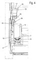
- the front molding 10 is here C-shaped, wherein a lower horizontal short leg of the molding 10, the guide rail 6 from below supports and the upper short leg of the molding 10 for fixing a pull-out and / or retraction movement of the drawer 2 supporting member 11th perpendicular to the extension direction x above the running rail 8 is used.
- two mutually facing spring elements 17,18 are integrally formed on the housing of the component 11, which engage behind the upper end 20 of the molding 10, so that the upper end 20 of the molding 10 is clamped between the housing main body and the spring elements 17,18 and so Component 11 stops.
- a protrusion 22 is preferably integrally formed on the housing of the component 11, which protrudes in the mounted state of the component 11 into a groove 21 in the upper end 20 of the molded part 10.
- the extraction and / or retraction movement of the drawer supporting component is designed for example as a self-closing. It is also conceivable training as ejection device or as a combination of an ejection device with a self-closing. According to a particular embodiment, the extracting and / or retracting movement of the drawer 2 supporting component 11 may also be formed with a damping device for damping the ejection movement or the retraction movement of the drawer 2.
- an end plug 12 is provided at the front, front end of the rails 8, which is equipped with an integrally molded activator 13 for controlling the component 11.
- This Activator 13 engages in tensioning any force accumulator of the component 11 in a lever of the component 11, said lever can tilt from a certain displacement in a position in which the activator 13 can leave the lever. In this case, this lever is secured in position and can only be moved back to its original position when the activator 13 when inserting the running rail 8 again comes into contact with the lever and moves it out of its blocking position.
- trained as a self-closing component 11 stored in the energy storage of Diseinzugs force is used to retract the track 8 and thus the drawer connected to its final insertion position.
- the activator 13 engages from below into the component 11, so that the functioning of the component 11 can not be adversely affected by falling in dirt.
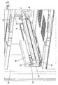
- the component 11 is covered at least from above, but preferably from above, left and right with a protective cover 19, such as in FIG. 5 is shown.
- a top with a spring element 14 is preferably provided at the rear end of the running rail 8, with which a lower outer edge of the drawer 2 can be clamped.
- a nose 16 is issued on the top of the running rail 8, which clamps together with an exhibited on the housing of the component 11 in the direction of the drawer 15, the outer edge of the drawer 2.
Landscapes
- Engineering & Computer Science (AREA)
- Mechanical Engineering (AREA)
- Chemical & Material Sciences (AREA)
- Combustion & Propulsion (AREA)
- Physics & Mathematics (AREA)
- Thermal Sciences (AREA)
- General Engineering & Computer Science (AREA)
- Drawers Of Furniture (AREA)
- Refrigerator Housings (AREA)
Description
- Die vorliegende Erfindung betrifft eine Auszugsführung eines beweglichen Elements eines Möbels oder Haushaltsgerätes, insbesondere eines Kühlgerätes gemäß dem Oberbegriff des Anspruchs 1.
- Gattungsgemäße Auszugsführungen für bewegliche Elemente, insbesondere Schubkästen sind in zahlreichen Ausführungsvarianten bekannt. Die
WO2010/011822 offenbart eine Steuervorrichtung für eine Auszugsführung, bei der eine Schiene über Rollen verfahrbar an einer Führungsschiene gehalten ist, wobei zum Abbremsen einer Schließbewegung eine Dämpfungseinrichtung vorgesehen ist. - Wie in der
DE 202008008121 U1 wird bei einer herkömmlichen Auszugsführung üblicherweise eine Führungsschiene der Auszugsführung an einem oder zwei am Korpus des Haushaltsgerätes vorgesehenen, tragenden Formteil(e) festgelegt. Häufig werden zur Bedienungserleichterung auch eine Auszugs- und/oder Einzugsbewegung des Schubkastens unterstützende Bauteile, wie beispielsweise ein Selbsteinzug oder eine Ausstoßvorrichtung, an der Auszugsführung montiert. - Der Einsatz dieser herkömmlichen Auszugsführungen ist in vielen Einsatzfällen problemlos möglich. Bei besonderem Einsatzzwecken, wie zum Beispiel in Gefrier- oder Kühlschränken, sind diese Auszugsführungen aus platz- und/oder hygienischen Gründen jedoch weniger gut geeignet.
- Aufgabe der vorliegenden Erfindung ist es, eine Auszugsführung eines beweglichen Elements eines Möbels oder Haushaltsgerätes bereitzustellen, die besonders platzsparend und in hygienisch unbedenklicher Weise im Korpus eines Möbels oder Haushaltsgerätes montierbar ist.
- Diese Aufgabe wird durch eine Auszugsführung eines beweglichen Elements eines Möbels oder Haushaltsgerätes mit den Merkmalen des Anspruchs 1 gelöst.
- Erfindungsgemäß ist der Aktivator einstückig mit einem die vordere Stirnseite der Laufschiene verschließenden Abschlussstopfen hergestellt.
- Durch die Platzierung dieses Bauteils oberhalb der Laufschiene ist zum Einen die horizontale Ausdehnung der Auszugsführung wesentlich reduziert, so dass dadurch die Breite des Möbels oder Haushaltsgerätes für die beweglichen Element optimal ausgenutzt werden kann. Zum Zweiten kann durch die Platzierung des die Auszugs- und/oder Einzugsbewegung des beweglichen Elements unterstützenden Bauteils oberhalb der Laufschiene der Auszugsführung nahezu kein Schmutz in das Bauteil eindringen.
- Vorteilhafte Ausgestaltungen der Erfindung sind Gegenstand der Unteransprüche.
- Gemäß einer Ausführungsvariante der Erfindung greift ein in der Laufschiene angeordneter Aktivator zur Steuerung des die Auszugs- und/oder Einzugsbewegung des beweglichen Elements unterstützenden Bauteils von unten in das Bauteil ein. Ein Eindringen von Schmutz in dieses Bauteil ist so zusätzlich wirksam verhindert.
- Gemäß einer weiteren Ausgestaltung der Erfindung ist das die Auszugs- und/oder Einzugsbewegung des beweglichen Elements unterstützende Bauteil zumindest von oben mit einer Schutzabdeckung abgedeckt.
- Erfindungsgemäß ist der Aktivator einstückig mit einem die vordere Stirnseite der Laufschiene verschließenden Abschlussstopfen hergestellt. Dadurch ist ein Anschweißen des Aktivators an der Laufschiene nicht mehr erforderlich, was beispielsweise bei geplanten Einsätzen der Auszugsführung für Gefrier- oder Kühlschränke schwierig wäre, da diese Auszugsführungen eine erhöhte Zinkauflage zur Verbesserung des Korrosionsschutzes benötigen.
- Gemäß einer weiteren Ausführungsvariante sind an dem die Auszugs- und/oder Einzugsbewegung des beweglichen Elements unterstützenden Bauteil zwei einander zugewandte Federelemente angeformt, die ein oberes Ende des Formteils hintergreifen.
- Das bewegliche Element kann beispielsweise als Tablarauszug, Apothekerauszug, Hochschrankauszug oder Schubkasten ausgeführt sein. Diese Aufzählung soll die Erfindung nicht auf diese Anwendungsfälle beschränken.
- Nachfolgend werden Ausführungsbeispiele der Erfindung anhand der beiliegenden Zeichnungen näher erläutert. Es zeigen:
- Figur 1
- eine perspektivische Darstellung eines Korpus eines als Gefriergerät ausgebildeten Haushaltsgerätes ohne Darstellung der Außenwände,
- Figur 2
- eine perspektivische Darstellung des Korpus aus
Figur 1 mit ausgezogenen Schubkasten, - Figur 3
- eine perspektivische Darstellung eines in den Gefriergerätekorpus eingebauten Ausführungsvariante einer erfindungsgemäßen Auszugsführung,
- Figur 4
- eine Ansicht von vorn auf die Auszugsführung aus
Figur 3 , - Figur 5
- eine perspektivische Ansicht der in den Korpus eingebauten Auszugsführung aus
Figur 4 mit aufgesetzter Schutzabdeckung - Figur 6
- eine perspektivische Explosionsdarstellung einer Ausführungsvariante der Auszugsführung,
- Figuren 7 und 8
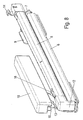
- perspektivische Ansichten einer Ausführungsvariante der Auszugsführung mit und ohne Schutzabdeckung,
- Figur 9
- eine weitere perspektivische Darstellung einer Ausführungsvariante der Auszugsführung aus einer rückwärtigen Perspektive,
- Figuren 10 und 11
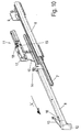
- perspektivische Darstellungen der Auszugsführung im ausgezogenen Zustand.
- In der nachfolgenden Figurenbeschreibung beziehen sich Begriffe wie oben, unten, links, rechts, vorne, hinten usw. ausschließlich auf die in den jeweiligen Figuren gewählte beispielhafte Darstellung und Position der Auszugsführung und anderer Teile. Diese Begriffe sind nicht einschränkend zu verstehen, das heißt, durch verschiedene Arbeitsstellungen oder die spiegelsymmetrische Auslegung oder dergleichen können sich diese Bezüge ändern.
- In den
Figuren 1 und2 ist mit dem Bezugszeichen 1 insgesamt ein Haushaltsgerät 1, insbesondere ein Kühlgerät wie beispielsweise ein Gefrierschrank, bezeichnet. Die äußeren Isolationswände des Gefrierschrankes sind hierbei nicht gezeigt. Das Gefriergerät weist in dem hier gezeigten Ausführungsbeispiel drei Schubkästen 2 auf. An den Seitenwänden 4 des Gefriergerätes sind nach außen hervorstehende Aufnahmen 3 zur Aufnahme der Auszugsführungen 5 der Schubkästen 2 angeformt. - Wie in den
Figuren 3-11 zu erkennen ist, bestehen die Auszugsführungen 5 bevorzugt aus einer über zwei Formteile 9,10 am Korpus 4 des Haushaltsgerätes lösbar festgelegten Führungsschiene 6, in der in bekannter Weise eine Mittelschiene 7 angeordnet ist, auf welche eine mit dem Schubkasten 2 verbundene Laufschiene 8 verfahrbar angeordnet ist. Eine Befestigung der Führungsschienen 6 an einem einzigen, gegebenenfalls breiter ausgelegten Formteil ist ebenfalls denkbar. - Das vordere Formteil 10 ist hier C-förmig ausgebildet, wobei ein unterer waagerechter kurzer Schenkel des Formteils 10 die Führungsschiene 6 von unten stützt und der obere kurze Schenkel des Formteils 10 zur Befestigung eines die Auszugs- und/oder Einzugsbewegung des Schubkastens 2 unterstützenden Bauteils 11 senkrecht zur Auszugsrichtung x oberhalb der Laufschiene 8 dient. Dazu sind an dem Gehäuse des Bauteils 11 zwei einander zugewandte Federelemente 17,18 angeformt, die das obere Ende 20 des Formteils 10 hintergreifen, so dass das obere Ende 20 des Formteils 10 zwischen den Gehäusehauptkörper und den Federelementen 17,18 eingeklemmt ist und so das Bauteil 11 hält. Zur positionsfesten Ausrichtung des Bauteils 11 ist am Gehäuse des Bauteils 11 bevorzugt eine Erhebung 22 angeformt, die im montierten Zustand des Bauteils 11 in eine Nut 21 in dem oberen Ende 20 des Formteils 10 hineinragt.
- Das die Auszugs- und/oder Einzugsbewegung des Schubkastens unterstützende Bauteil ist beispielsweise als Selbsteinzug ausgebildet. Denkbar ist auch eine Ausbildung als Ausstoßvorrichtung oder als Kombination einer Ausstoßvorrichtung mit einem Selbsteinzug. Gemäß einer besonderen Ausführungsvariante kann das die Auszugs- und/oder Einzugsbewegung des Schubkastens 2 unterstützende Bauteil 11 auch mit einer Dämpfungseinrichtung zur Abdämpfung der Ausstoßbewegung oder der Einzugsbewegung des Schubkastens 2 ausgebildet sein.
- Zur Steuerung des Bauteils 11 ist am vorderen, stirnseitigen Ende der Laufschienen 8 ein Abschlussstopfen 12 vorgesehen, der mit einem einstückig angeformten Aktivator 13 zur Steuerung des Bauteils 11 ausgestattet ist. Dieser Aktivator 13 greift beim Spannen eines beliebigen Kraftspeichers des Bauteils 11 in einen Hebel des Bauteils 11 ein, wobei dieser Hebel ab einem bestimmten Verschiebeweg in eine Position kippen kann, in welcher der Aktivator 13 den Hebel verlassen kann. Dabei ist dieser Hebel in seiner Position gesichert und kann erst dann wieder in seine Ausgangsposition zurückbewegt werden, wenn der Aktivator 13 beim Einschieben der Laufschiene 8 wieder mit dem Hebel in Kontakt kommt und diesen aus seiner Blockierstellung herausbewegt. Im Falle eines als Selbsteinzug ausgebildeten Bauteils 11 wird die im Kraftspeicher des Selbsteinzugs gespeicherte Kraft genutzt, um die Laufschiene 8 und somit den damit verbundenen Schubkasten in seine endgültige Einschubposition zurückzuziehen.
- Wichtig ist hier, dass der Aktivator 13 von unten in das Bauteil 11 eingreift, so dass die Funktionsweise des Bauteils 11 nicht durch hineinfallenden Schmutz beeinträgtigt werden kann. Um auch weitere an dem Gehäuse des Bauteils 11 vorhandene Öffnungen vor dem eindringen von Schmutz zu bewahren, ist das Bauteil 11 zumindest von oben, bevorzugt aber von oben, links und rechts mit einer Schutzabdeckung 19 abgedeckt, wie beispielsweise in
Figur 5 gezeigt ist. - Zur Arretierung des Schubkastens 2 an der Laufschiene 8 ist am hinteren Ende der Laufschiene 8 bevorzugt ein Aufsatz mit einem Federelement 14 vorgesehen, mit dem ein unterer Außenrand des Schubkastens 2 festklemmbar ist. Zur Arretierung dieses Schubkastenrandes im vorderen Bereich der Laufschiene 8 ist auf der Oberseite der Laufschiene 8 eine Nase 16 ausgestellt, die zusammen mit einer am Gehäuse des Bauteils 11 in Richtung des Schubkastens ausgestellten Steg 15 den Außenrand des Schubkastens 2 klemmt.
-
- Haushaltsgerät
- 1
- Schubkästen
- 2
- Aufnahmen
- 3
- Seitenwänden
- 4
- Auszugsführungen
- 5
- Führungsschiene
- 6
- Mittelschiene
- 7
- Laufschiene
- 8
- Formteile
- 9
- Formteile
- 10
- Bauteils
- 11
- Abschlussstopfen
- 12
- Aktivator
- 13
- Federelement
- 14
- Steg
- 15
- Nase
- 16
- Federelement
- 17
- Federelement
- 18
- Schutzabdeckung
- 19
- obere Ende
- 20
- Nut
- 21
- Erhebung
- 22
- Auszugsrichtung
- x
Claims (9)
- Auszugsführung (5) eines beweglichen Elements (2) eines Möbels oder Haushaltsgerätes (1), insbesondere eines Kühlgerätes, aufweisend eine am Korpus (4) des Möbels oder Haushaltsgerätes (1) festlegbare Führungsschiene (6) und eine mit dem beweglichen Element (2) verbindbare Laufschiene (8), wobei die Führungsschiene (6) an mindestens einem am Korpus (4) des Möbels oder Haushaltsgerätes (1) vorgesehenen, tragenden Formteil (9, 10) der Auszugsführung lösbar festgelegbar ist, sowie ein die Auszugs- und/oder Einzugsbewegung des beweglichen Elements (2) unterstützendes Bauteil (11), wobei das die Auszugs- und/oder Einzugsbewegung des beweglichen Elements (2) unterstützende Bauteil (11) senkrecht zur Auszugsrichtung (x) oberhalb der Laufschiene (8) an dem Formteil (10) befestigt ist, wobei ein an der Laufschiene (8) angeordneter Aktivator (13) zur Steuerung des die Auszugs- und/oder Einzugsbewegung des beweglichen Elements (2) unterstützenden Bauteils (11) von unten in das Bauteil (11) eingreift, dadurch gekennzeichnet, dass der Aktivator (13) einstückig mit einem die vordere Stirnseite der Laufschiene (8) verschließenden Abschlussstopfen (12) hergestellt ist.
- Auszugsführung nach Anspruch 1, dadurch gekennzeichnet, dass das die Auszugs- und/oder Einzugsbewegung des beweglichen Elements (2) unterstützende Bauteil (11) als Selbsteinzug und/oder Ausstoßvorrichtung ausgebildet ist.
- Auszugsführung nach Anspruch 2, dadurch gekennzeichnet, dass das die Auszugs- und/oder Einzugsbewegung des beweglichen Elements (2) unterstützende Bauteil (11) mit einer Dämpfungseinrichtung ausgebildet ist.
- Auszugsführung nach einem der vorhergehenden Ansprüche, dadurch gekennzeichnet, dass das die Auszugs- und/oder Einzugsbewegung des beweglichen Elements (2) unterstützende Bauteil (11) zumindest von oben mit einer Schutzabdeckung (19) abgedeckt ist.
- Auszugsführung nach einem der vorstehenden Ansprüche, dadurch gekennzeichnet, dass das die Auszugs- und/oder Einzugsbewegung des beweglichen Elements (2) unterstützende Bauteil (11) an dem Formteil (10) verrastet ist.
- Auszugsführung nach Anspruch 5, dadurch gekennzeichnet, dass an dem die Auszugs- und/oder Einzugsbewegung des beweglichen Elements (2) unterstützenden Bauteil (11) zwei einander zugewandte Federelemente (17,18) angeformt sind, die ein oberes Ende (20) des Formteils (10) hintergreifen.
- Auszugsführung nach Anspruch 6, dadurch gekennzeichnet, dass an dem Gehäuse des die Auszugs- und/oder Einzugsbewegung des beweglichen Elements (2) unterstützenden Bauteils (11) eine Erhebung (22) angeformt ist, die im montierten Zustand des Bauteils (11) in eine Nut (21) in dem oberes Ende (20) des Formteils (10) ragt.
- Auszugsführung nach einem der vorstehenden Ansprüche, dadurch gekennzeichnet, dass das bewegliche Element (2) als Schubkasten ausgeführt ist.
- Haushaltsgerät, insbesondere Kühlgerät, mit mindestens einem Schubkasten (2) mit Auszugsführungen (5), dadurch gekennzeichnet, dass mindestens einer der Auszugsführungen (5) gemäß einem oder mehreren der vorstehenden Ansprüche ausgebildet ist.
Priority Applications (1)
| Application Number | Priority Date | Filing Date | Title |
|---|---|---|---|
| PL11702967T PL2531067T3 (pl) | 2010-02-02 | 2011-02-01 | Prowadnica wysuwana szuflady |
Applications Claiming Priority (2)
| Application Number | Priority Date | Filing Date | Title |
|---|---|---|---|
| DE102010000279A DE102010000279A1 (de) | 2010-02-02 | 2010-02-02 | Auszugsführung eines Schubkastens |
| PCT/EP2011/051381 WO2011095476A1 (de) | 2010-02-02 | 2011-02-01 | Auszugsführung eines schubkastens |
Publications (2)
| Publication Number | Publication Date |
|---|---|
| EP2531067A1 EP2531067A1 (de) | 2012-12-12 |
| EP2531067B1 true EP2531067B1 (de) | 2015-05-06 |
Family
ID=44144885
Family Applications (1)
| Application Number | Title | Priority Date | Filing Date |
|---|---|---|---|
| EP11702967.8A Active EP2531067B1 (de) | 2010-02-02 | 2011-02-01 | Auszugsführung eines schubkastens |
Country Status (7)
| Country | Link |
|---|---|
| US (1) | US8979222B2 (de) |
| EP (1) | EP2531067B1 (de) |
| KR (1) | KR20120140654A (de) |
| CN (1) | CN102686128B (de) |
| DE (1) | DE102010000279A1 (de) |
| PL (1) | PL2531067T3 (de) |
| WO (1) | WO2011095476A1 (de) |
Families Citing this family (22)
| Publication number | Priority date | Publication date | Assignee | Title |
|---|---|---|---|---|
| KR101899808B1 (ko) * | 2011-11-18 | 2018-09-20 | 엘지전자 주식회사 | 냉장고 |
| GB2496864B (en) * | 2011-11-22 | 2016-08-31 | Titus Int Ltd | Improvements in damper assemblies |
| DE102012100683A1 (de) * | 2012-01-27 | 2013-08-01 | Paul Hettich Gmbh & Co | Führungsschiene einer Auszugsführung |
| DE102012105799B4 (de) * | 2012-06-29 | 2024-11-07 | Paul Hettich Gmbh & Co. Kg | Auszugssystem |
| US20140042884A1 (en) * | 2012-08-08 | 2014-02-13 | Grass America, Inc. | Control mechanism for drawer slide assembly |
| DE102012109752A1 (de) * | 2012-10-12 | 2014-04-17 | Paul Hettich Gmbh & Co. Kg | Ausstoßvorrichtung |
| KR101860713B1 (ko) * | 2013-02-23 | 2018-05-24 | 삼성전자주식회사 | 슬라이딩 장치 및 이를 갖는 냉장고 |
| DE102013114309A1 (de) * | 2013-12-18 | 2015-06-18 | Paul Hettich Gmbh & Co. Kg | Einzugs- und Dämpfungseinheit für ein Schiebeelement |
| DE102014104733A1 (de) * | 2014-04-03 | 2015-10-08 | Paul Hettich Gmbh & Co. Kg | Schiebe-Schwenkmechanik einer Ablage eines Möbels oder Haushaltsgerätes, Haushaltsgerät und Möbel |
| CN105333686B (zh) * | 2014-08-01 | 2019-12-20 | 博西华家用电器有限公司 | 制冷设备 |
| CN104976845A (zh) * | 2015-07-31 | 2015-10-14 | 合肥华凌股份有限公司 | 冰箱 |
| DE202015006277U1 (de) * | 2015-09-04 | 2017-01-17 | Grass Gmbh | Vorrichtung zur Befestigung von Zubehörteilen an einer Möbelkomponente eines Möbels |
| US11131141B2 (en) * | 2016-03-20 | 2021-09-28 | Hideaway Solutions Llc | Lateral folding step unit |
| TWI623288B (zh) * | 2016-09-24 | 2018-05-11 | 川湖科技股份有限公司 | 用於機架的滑軌安裝配件總成 |
| DE102016120588A1 (de) * | 2016-10-27 | 2018-05-03 | Paul Hettich Gmbh & Co. Kg | Möbel und Verfahren zum Öffnen eines Schubkastens und eines Innenschubkastens |
| US10356931B1 (en) * | 2017-05-26 | 2019-07-16 | King Slide Works Co., Ltd. | Rack mounting system |
| DE102018104398A1 (de) * | 2018-02-27 | 2019-08-29 | Paul Hettich Gmbh & Co. Kg | Möbel oder Haushaltsgerät und Verfahren zur Montage einer Funktionseinheit eines Schubelements in einem Möbel oder Haushaltsgerät |
| CN111174754B (zh) * | 2019-12-30 | 2021-07-23 | 陕西建工第九建设集团有限公司 | 一种建筑沉降装置观测点 |
| US11871846B2 (en) * | 2021-01-29 | 2024-01-16 | Tenn-Tex Plastics, Inc. | Hardware assembly for drawer slide with dampening mechanism |
| US11920401B2 (en) | 2021-05-03 | 2024-03-05 | Kohler Co. | Slow close mechanism for sliding applications |
| US11969088B2 (en) * | 2021-12-22 | 2024-04-30 | Grass America, Inc. | Guide rail, guide system and furniture item |
| TWI850157B (zh) * | 2023-11-21 | 2024-07-21 | 川湖科技股份有限公司 | 配件總成及其配件裝置 |
Family Cites Families (19)
| Publication number | Priority date | Publication date | Assignee | Title |
|---|---|---|---|---|
| US3918752A (en) * | 1974-04-11 | 1975-11-11 | Adolph A Leone | Safety locking device |
| KR970000100B1 (ko) * | 1993-12-02 | 1997-01-04 | 엘지전자 주식회사 | 냉장고의 야채실도어 개폐장치 |
| US5597220A (en) | 1995-02-15 | 1997-01-28 | Grass America, Inc. | Bracket for mounting a drawer guide supporting a moveable structure for use in a desk or cabinet |
| DE19835466B4 (de) * | 1998-08-06 | 2004-08-05 | Grass Ges.m.b.H., Metallwarenfabrik, Höchst | Bremsvorrichtung mit Schließfolgeregler für bewegliche Möbelteile |
| IT250443Y1 (it) * | 2000-09-19 | 2003-09-10 | Salice Arturo Spa | Dispositivo per la chiusura decelerata di parti di mobile scorrevoli |
| TW564720U (en) * | 2002-06-20 | 2003-12-01 | Nan Juen Int Co Ltd | Buffering and returning device for drawer rail |
| KR20040025316A (ko) | 2002-09-19 | 2004-03-24 | 삼성전자주식회사 | 서랍식 냉장고 |
| TW563464U (en) * | 2003-03-04 | 2003-11-21 | Nan Juen Int Co Ltd | Folding buffer device for drawer rail |
| DE102005021558A1 (de) * | 2005-05-10 | 2006-11-16 | BSH Bosch und Siemens Hausgeräte GmbH | Kältegerät mit ausziehbarem Kühlgutträger |
| US20070046159A1 (en) * | 2005-08-25 | 2007-03-01 | Knape & Vogt Manufacturing Co. | Motion control bracket with integrated motion control device |
| KR20070042059A (ko) * | 2005-10-17 | 2007-04-20 | 삼성전자주식회사 | 냉장고 |
| DE102006057582C5 (de) * | 2005-12-07 | 2018-10-31 | Lg Electronics Inc. | Kühlschrankschienenanordnung und Kühlschranklagerbehälterauszugs-/-Einschubvorrichtung mit derselben |
| DE202006019009U1 (de) * | 2006-12-14 | 2008-04-24 | Paul Hettich Gmbh & Co. Kg | Teleskopführungsschiene für Möbelauszüge wie Schubkästen o.dgl. |
| DE102006061096A1 (de) * | 2006-12-22 | 2008-06-26 | BSH Bosch und Siemens Hausgeräte GmbH | Teleskopauszug |
| US7708357B2 (en) * | 2007-03-20 | 2010-05-04 | Weon-Dong Cho | Automatic locking apparatus used in guide rail for drawer |
| DE102008014871B4 (de) * | 2008-03-18 | 2022-03-10 | "REME-Möbelbeschläge GmbH" | Einrichtung zum Bewegen eines Möbelteils |
| DE202008008121U1 (de) | 2008-06-19 | 2009-10-29 | Paul Hettich Gmbh & Co. Kg | Auszugsführung für Möbelauszugsteile |
| DE102008031462B4 (de) * | 2008-07-09 | 2019-06-19 | Grass Gmbh | Motorische Antriebsvorrichtung für Schubladen |
| CN102065726A (zh) * | 2008-07-24 | 2011-05-18 | 格拉斯美国公司 | 用于抽屉滑动装置的控制机构 |
-
2010
- 2010-02-02 DE DE102010000279A patent/DE102010000279A1/de not_active Ceased
-
2011
- 2011-02-01 EP EP11702967.8A patent/EP2531067B1/de active Active
- 2011-02-01 PL PL11702967T patent/PL2531067T3/pl unknown
- 2011-02-01 CN CN201180005321.5A patent/CN102686128B/zh active Active
- 2011-02-01 KR KR1020127023085A patent/KR20120140654A/ko not_active Abandoned
- 2011-02-01 US US13/522,416 patent/US8979222B2/en not_active Expired - Fee Related
- 2011-02-01 WO PCT/EP2011/051381 patent/WO2011095476A1/de not_active Ceased
Also Published As
| Publication number | Publication date |
|---|---|
| CN102686128A (zh) | 2012-09-19 |
| US8979222B2 (en) | 2015-03-17 |
| PL2531067T3 (pl) | 2015-11-30 |
| WO2011095476A1 (de) | 2011-08-11 |
| EP2531067A1 (de) | 2012-12-12 |
| DE102010000279A1 (de) | 2011-08-04 |
| CN102686128B (zh) | 2014-07-02 |
| KR20120140654A (ko) | 2012-12-31 |
| US20120288221A1 (en) | 2012-11-15 |
Similar Documents
| Publication | Publication Date | Title |
|---|---|---|
| WO2011095476A1 (de) | Auszugsführung eines schubkastens | |
| AT511081B1 (de) | Anordnung mit einer schublade und mit einer schubladenausziehführung | |
| EP2890271B1 (de) | Schiebe-schwenkmechanik einer ablage eines möbels, möbel und haushaltsgerät | |
| AT517064B1 (de) | Einzugsvorrichtung zum Einbau in eine Auszugsführung | |
| EP3238568B1 (de) | Schubladensystem | |
| AT508139B1 (de) | Möbelantrieb mit touch-latch-vorrichtung | |
| EP1868465B1 (de) | Teleskopauszug für ein kältegerät | |
| DE102011115662B4 (de) | Verstellbare automatische Rückstellvorrichtung mit Pufferwirkung für eine Schiebetür | |
| DE102016107918A1 (de) | Ausstoßvorrichtung für ein bewegbares Möbelteil und Möbel | |
| DE102013114309A1 (de) | Einzugs- und Dämpfungseinheit für ein Schiebeelement | |
| DE102010017132A1 (de) | Schrankmöbel mit einem Frontschubkasten und einem Innenschubkasten | |
| EP2276986A1 (de) | Kältegerät | |
| DE202015105093U1 (de) | Ausziehsperrvorrichtung und Möbel | |
| DE202005006716U1 (de) | Möbel mit synchronisiert geführtem Auszug | |
| EP1513429B1 (de) | Anordung für die verbindung einer schubladenzarge mit dem boden einer schublade | |
| EP2281482B1 (de) | Ausstoßvorrichtung einer Ausziehführung und Ausziehführung | |
| EP2526823B1 (de) | Schrankelement mit einem Schrankauszug | |
| EP2844108B1 (de) | Haltevorrichtung für ein tragelement eines schrankes sowie kühl-, gefrierschrank oder weinlagerungsschrank | |
| DE202008012999U1 (de) | Führungsschiene einer Möbelauszugsführung | |
| DE102008026381A1 (de) | Türablagefach für ein Kältegerät | |
| WO2019166205A1 (de) | Möbel oder haushaltsgerät und verfahren zur montage einer funktionseinheit eines schubelements in einem möbel oder haushaltsgerät | |
| WO2019197133A1 (de) | Auszugsführung | |
| DE202009002035U1 (de) | Auszugsführung | |
| DE202008012996U1 (de) | Möbelauszugsführung | |
| WO2006063968A1 (de) | Teleskopführungsschiene für möbelauszüge |
Legal Events
| Date | Code | Title | Description |
|---|---|---|---|
| PUAI | Public reference made under article 153(3) epc to a published international application that has entered the european phase |
Free format text: ORIGINAL CODE: 0009012 |
|
| 17P | Request for examination filed |
Effective date: 20120807 |
|
| AK | Designated contracting states |
Kind code of ref document: A1 Designated state(s): AL AT BE BG CH CY CZ DE DK EE ES FI FR GB GR HR HU IE IS IT LI LT LU LV MC MK MT NL NO PL PT RO RS SE SI SK SM TR |
|
| DAX | Request for extension of the european patent (deleted) | ||
| GRAP | Despatch of communication of intention to grant a patent |
Free format text: ORIGINAL CODE: EPIDOSNIGR1 |
|
| INTG | Intention to grant announced |
Effective date: 20141209 |
|
| RIN1 | Information on inventor provided before grant (corrected) |
Inventor name: JAEHRLING, PETER Inventor name: HEMMINGER, ALEXANDER |
|
| GRAS | Grant fee paid |
Free format text: ORIGINAL CODE: EPIDOSNIGR3 |
|
| GRAA | (expected) grant |
Free format text: ORIGINAL CODE: 0009210 |
|
| AK | Designated contracting states |
Kind code of ref document: B1 Designated state(s): AL AT BE BG CH CY CZ DE DK EE ES FI FR GB GR HR HU IE IS IT LI LT LU LV MC MK MT NL NO PL PT RO RS SE SI SK SM TR |
|
| REG | Reference to a national code |
Ref country code: GB Ref legal event code: FG4D Free format text: NOT ENGLISH |
|
| REG | Reference to a national code |
Ref country code: CH Ref legal event code: EP |
|
| REG | Reference to a national code |
Ref country code: IE Ref legal event code: FG4D Free format text: LANGUAGE OF EP DOCUMENT: GERMAN |
|
| REG | Reference to a national code |
Ref country code: AT Ref legal event code: REF Ref document number: 725089 Country of ref document: AT Kind code of ref document: T Effective date: 20150615 |
|
| REG | Reference to a national code |
Ref country code: DE Ref legal event code: R096 Ref document number: 502011006775 Country of ref document: DE Effective date: 20150618 |
|
| REG | Reference to a national code |
Ref country code: NL Ref legal event code: MP Effective date: 20150506 |
|
| REG | Reference to a national code |
Ref country code: LT Ref legal event code: MG4D |
|
| PG25 | Lapsed in a contracting state [announced via postgrant information from national office to epo] |
Ref country code: PT Free format text: LAPSE BECAUSE OF FAILURE TO SUBMIT A TRANSLATION OF THE DESCRIPTION OR TO PAY THE FEE WITHIN THE PRESCRIBED TIME-LIMIT Effective date: 20150907 Ref country code: FI Free format text: LAPSE BECAUSE OF FAILURE TO SUBMIT A TRANSLATION OF THE DESCRIPTION OR TO PAY THE FEE WITHIN THE PRESCRIBED TIME-LIMIT Effective date: 20150506 Ref country code: NO Free format text: LAPSE BECAUSE OF FAILURE TO SUBMIT A TRANSLATION OF THE DESCRIPTION OR TO PAY THE FEE WITHIN THE PRESCRIBED TIME-LIMIT Effective date: 20150806 Ref country code: LT Free format text: LAPSE BECAUSE OF FAILURE TO SUBMIT A TRANSLATION OF THE DESCRIPTION OR TO PAY THE FEE WITHIN THE PRESCRIBED TIME-LIMIT Effective date: 20150506 Ref country code: HR Free format text: LAPSE BECAUSE OF FAILURE TO SUBMIT A TRANSLATION OF THE DESCRIPTION OR TO PAY THE FEE WITHIN THE PRESCRIBED TIME-LIMIT Effective date: 20150506 Ref country code: ES Free format text: LAPSE BECAUSE OF FAILURE TO SUBMIT A TRANSLATION OF THE DESCRIPTION OR TO PAY THE FEE WITHIN THE PRESCRIBED TIME-LIMIT Effective date: 20150506 |
|
| PG25 | Lapsed in a contracting state [announced via postgrant information from national office to epo] |
Ref country code: RS Free format text: LAPSE BECAUSE OF FAILURE TO SUBMIT A TRANSLATION OF THE DESCRIPTION OR TO PAY THE FEE WITHIN THE PRESCRIBED TIME-LIMIT Effective date: 20150506 Ref country code: GR Free format text: LAPSE BECAUSE OF FAILURE TO SUBMIT A TRANSLATION OF THE DESCRIPTION OR TO PAY THE FEE WITHIN THE PRESCRIBED TIME-LIMIT Effective date: 20150807 Ref country code: BG Free format text: LAPSE BECAUSE OF FAILURE TO SUBMIT A TRANSLATION OF THE DESCRIPTION OR TO PAY THE FEE WITHIN THE PRESCRIBED TIME-LIMIT Effective date: 20150806 Ref country code: LV Free format text: LAPSE BECAUSE OF FAILURE TO SUBMIT A TRANSLATION OF THE DESCRIPTION OR TO PAY THE FEE WITHIN THE PRESCRIBED TIME-LIMIT Effective date: 20150506 Ref country code: IS Free format text: LAPSE BECAUSE OF FAILURE TO SUBMIT A TRANSLATION OF THE DESCRIPTION OR TO PAY THE FEE WITHIN THE PRESCRIBED TIME-LIMIT Effective date: 20150906 |
|
| REG | Reference to a national code |
Ref country code: PL Ref legal event code: T3 |
|
| PG25 | Lapsed in a contracting state [announced via postgrant information from national office to epo] |
Ref country code: EE Free format text: LAPSE BECAUSE OF FAILURE TO SUBMIT A TRANSLATION OF THE DESCRIPTION OR TO PAY THE FEE WITHIN THE PRESCRIBED TIME-LIMIT Effective date: 20150506 Ref country code: DK Free format text: LAPSE BECAUSE OF FAILURE TO SUBMIT A TRANSLATION OF THE DESCRIPTION OR TO PAY THE FEE WITHIN THE PRESCRIBED TIME-LIMIT Effective date: 20150506 |
|
| REG | Reference to a national code |
Ref country code: DE Ref legal event code: R097 Ref document number: 502011006775 Country of ref document: DE |
|
| PG25 | Lapsed in a contracting state [announced via postgrant information from national office to epo] |
Ref country code: RO Free format text: LAPSE BECAUSE OF NON-PAYMENT OF DUE FEES Effective date: 20150506 Ref country code: CZ Free format text: LAPSE BECAUSE OF FAILURE TO SUBMIT A TRANSLATION OF THE DESCRIPTION OR TO PAY THE FEE WITHIN THE PRESCRIBED TIME-LIMIT Effective date: 20150506 Ref country code: SK Free format text: LAPSE BECAUSE OF FAILURE TO SUBMIT A TRANSLATION OF THE DESCRIPTION OR TO PAY THE FEE WITHIN THE PRESCRIBED TIME-LIMIT Effective date: 20150506 |
|
| PLBE | No opposition filed within time limit |
Free format text: ORIGINAL CODE: 0009261 |
|
| STAA | Information on the status of an ep patent application or granted ep patent |
Free format text: STATUS: NO OPPOSITION FILED WITHIN TIME LIMIT |
|
| 26N | No opposition filed |
Effective date: 20160209 |
|
| PG25 | Lapsed in a contracting state [announced via postgrant information from national office to epo] |
Ref country code: BE Free format text: LAPSE BECAUSE OF NON-PAYMENT OF DUE FEES Effective date: 20160229 Ref country code: SI Free format text: LAPSE BECAUSE OF FAILURE TO SUBMIT A TRANSLATION OF THE DESCRIPTION OR TO PAY THE FEE WITHIN THE PRESCRIBED TIME-LIMIT Effective date: 20150506 |
|
| PG25 | Lapsed in a contracting state [announced via postgrant information from national office to epo] |
Ref country code: MC Free format text: LAPSE BECAUSE OF FAILURE TO SUBMIT A TRANSLATION OF THE DESCRIPTION OR TO PAY THE FEE WITHIN THE PRESCRIBED TIME-LIMIT Effective date: 20150506 Ref country code: LU Free format text: LAPSE BECAUSE OF FAILURE TO SUBMIT A TRANSLATION OF THE DESCRIPTION OR TO PAY THE FEE WITHIN THE PRESCRIBED TIME-LIMIT Effective date: 20160201 |
|
| REG | Reference to a national code |
Ref country code: CH Ref legal event code: PL |
|
| GBPC | Gb: european patent ceased through non-payment of renewal fee |
Effective date: 20160201 |
|
| PG25 | Lapsed in a contracting state [announced via postgrant information from national office to epo] |
Ref country code: LI Free format text: LAPSE BECAUSE OF NON-PAYMENT OF DUE FEES Effective date: 20160229 Ref country code: CH Free format text: LAPSE BECAUSE OF NON-PAYMENT OF DUE FEES Effective date: 20160229 |
|
| REG | Reference to a national code |
Ref country code: FR Ref legal event code: ST Effective date: 20161028 |
|
| REG | Reference to a national code |
Ref country code: DE Ref legal event code: R079 Ref document number: 502011006775 Country of ref document: DE Free format text: PREVIOUS MAIN CLASS: A47B0088040000 Ipc: A47B0088400000 |
|
| REG | Reference to a national code |
Ref country code: IE Ref legal event code: MM4A |
|
| PG25 | Lapsed in a contracting state [announced via postgrant information from national office to epo] |
Ref country code: GB Free format text: LAPSE BECAUSE OF NON-PAYMENT OF DUE FEES Effective date: 20160201 Ref country code: FR Free format text: LAPSE BECAUSE OF NON-PAYMENT OF DUE FEES Effective date: 20160229 Ref country code: IE Free format text: LAPSE BECAUSE OF NON-PAYMENT OF DUE FEES Effective date: 20160201 |
|
| REG | Reference to a national code |
Ref country code: AT Ref legal event code: MM01 Ref document number: 725089 Country of ref document: AT Kind code of ref document: T Effective date: 20160201 |
|
| PG25 | Lapsed in a contracting state [announced via postgrant information from national office to epo] |
Ref country code: AT Free format text: LAPSE BECAUSE OF NON-PAYMENT OF DUE FEES Effective date: 20160201 |
|
| PG25 | Lapsed in a contracting state [announced via postgrant information from national office to epo] |
Ref country code: IT Free format text: LAPSE BECAUSE OF NON-PAYMENT OF DUE FEES Effective date: 20160201 Ref country code: SE Free format text: LAPSE BECAUSE OF FAILURE TO SUBMIT A TRANSLATION OF THE DESCRIPTION OR TO PAY THE FEE WITHIN THE PRESCRIBED TIME-LIMIT Effective date: 20150506 Ref country code: NL Free format text: LAPSE BECAUSE OF FAILURE TO SUBMIT A TRANSLATION OF THE DESCRIPTION OR TO PAY THE FEE WITHIN THE PRESCRIBED TIME-LIMIT Effective date: 20150506 |
|
| PG25 | Lapsed in a contracting state [announced via postgrant information from national office to epo] |
Ref country code: PL Free format text: LAPSE BECAUSE OF NON-PAYMENT OF DUE FEES Effective date: 20160201 Ref country code: MT Free format text: LAPSE BECAUSE OF FAILURE TO SUBMIT A TRANSLATION OF THE DESCRIPTION OR TO PAY THE FEE WITHIN THE PRESCRIBED TIME-LIMIT Effective date: 20150506 |
|
| PG25 | Lapsed in a contracting state [announced via postgrant information from national office to epo] |
Ref country code: HU Free format text: LAPSE BECAUSE OF FAILURE TO SUBMIT A TRANSLATION OF THE DESCRIPTION OR TO PAY THE FEE WITHIN THE PRESCRIBED TIME-LIMIT; INVALID AB INITIO Effective date: 20110201 Ref country code: CY Free format text: LAPSE BECAUSE OF FAILURE TO SUBMIT A TRANSLATION OF THE DESCRIPTION OR TO PAY THE FEE WITHIN THE PRESCRIBED TIME-LIMIT Effective date: 20150506 Ref country code: SM Free format text: LAPSE BECAUSE OF FAILURE TO SUBMIT A TRANSLATION OF THE DESCRIPTION OR TO PAY THE FEE WITHIN THE PRESCRIBED TIME-LIMIT Effective date: 20150506 |
|
| PG25 | Lapsed in a contracting state [announced via postgrant information from national office to epo] |
Ref country code: MK Free format text: LAPSE BECAUSE OF FAILURE TO SUBMIT A TRANSLATION OF THE DESCRIPTION OR TO PAY THE FEE WITHIN THE PRESCRIBED TIME-LIMIT Effective date: 20150506 |
|
| PG25 | Lapsed in a contracting state [announced via postgrant information from national office to epo] |
Ref country code: AL Free format text: LAPSE BECAUSE OF FAILURE TO SUBMIT A TRANSLATION OF THE DESCRIPTION OR TO PAY THE FEE WITHIN THE PRESCRIBED TIME-LIMIT Effective date: 20150506 |
|
| P01 | Opt-out of the competence of the unified patent court (upc) registered |
Effective date: 20230420 |
|
| PG25 | Lapsed in a contracting state [announced via postgrant information from national office to epo] |
Ref country code: TR Free format text: LAPSE BECAUSE OF NON-PAYMENT OF DUE FEES Effective date: 20160201 |
|
| PGFP | Annual fee paid to national office [announced via postgrant information from national office to epo] |
Ref country code: DE Payment date: 20260217 Year of fee payment: 16 |