EP2530529B1 - Image forming apparatus, control method of image forming apparatus and storage medium - Google Patents
Image forming apparatus, control method of image forming apparatus and storage medium Download PDFInfo
- Publication number
- EP2530529B1 EP2530529B1 EP12169877.3A EP12169877A EP2530529B1 EP 2530529 B1 EP2530529 B1 EP 2530529B1 EP 12169877 A EP12169877 A EP 12169877A EP 2530529 B1 EP2530529 B1 EP 2530529B1
- Authority
- EP
- European Patent Office
- Prior art keywords
- image forming
- forming apparatus
- packet
- power supply
- power
- Prior art date
- Legal status (The legal status is an assumption and is not a legal conclusion. Google has not performed a legal analysis and makes no representation as to the accuracy of the status listed.)
- Active
Links
- 238000000034 method Methods 0.000 title claims description 15
- 238000012545 processing Methods 0.000 claims description 57
- 238000004891 communication Methods 0.000 description 31
- 238000010586 diagram Methods 0.000 description 10
- 230000006870 function Effects 0.000 description 10
- 230000005764 inhibitory process Effects 0.000 description 7
- 238000012986 modification Methods 0.000 description 7
- 230000004048 modification Effects 0.000 description 7
- 230000005611 electricity Effects 0.000 description 6
- 230000007704 transition Effects 0.000 description 6
- 230000002093 peripheral effect Effects 0.000 description 4
- 238000012546 transfer Methods 0.000 description 4
- 230000003213 activating effect Effects 0.000 description 3
- 230000015572 biosynthetic process Effects 0.000 description 2
- 230000000694 effects Effects 0.000 description 2
- 238000005516 engineering process Methods 0.000 description 2
- 239000011521 glass Substances 0.000 description 2
- 230000003287 optical effect Effects 0.000 description 2
- 238000004364 calculation method Methods 0.000 description 1
- 238000013500 data storage Methods 0.000 description 1
- 239000004973 liquid crystal related substance Substances 0.000 description 1
- 238000007639 printing Methods 0.000 description 1
- 239000002699 waste material Substances 0.000 description 1
Images


Classifications
-
- G—PHYSICS
- G06—COMPUTING; CALCULATING OR COUNTING
- G06K—GRAPHICAL DATA READING; PRESENTATION OF DATA; RECORD CARRIERS; HANDLING RECORD CARRIERS
- G06K15/00—Arrangements for producing a permanent visual presentation of the output data, e.g. computer output printers
- G06K15/40—Details not directly involved in printing, e.g. machine management, management of the arrangement as a whole or of its constitutive parts
- G06K15/4055—Managing power consumption, e.g. standby mode
- G06K15/406—Wake-up procedures
-
- G—PHYSICS
- G06—COMPUTING; CALCULATING OR COUNTING
- G06F—ELECTRIC DIGITAL DATA PROCESSING
- G06F1/00—Details not covered by groups G06F3/00 - G06F13/00 and G06F21/00
- G06F1/26—Power supply means, e.g. regulation thereof
-
- G—PHYSICS
- G03—PHOTOGRAPHY; CINEMATOGRAPHY; ANALOGOUS TECHNIQUES USING WAVES OTHER THAN OPTICAL WAVES; ELECTROGRAPHY; HOLOGRAPHY
- G03G—ELECTROGRAPHY; ELECTROPHOTOGRAPHY; MAGNETOGRAPHY
- G03G15/00—Apparatus for electrographic processes using a charge pattern
- G03G15/50—Machine control of apparatus for electrographic processes using a charge pattern, e.g. regulating differents parts of the machine, multimode copiers, microprocessor control
- G03G15/5004—Power supply control, e.g. power-saving mode, automatic power turn-off
-
- G—PHYSICS
- G03—PHOTOGRAPHY; CINEMATOGRAPHY; ANALOGOUS TECHNIQUES USING WAVES OTHER THAN OPTICAL WAVES; ELECTROGRAPHY; HOLOGRAPHY
- G03G—ELECTROGRAPHY; ELECTROPHOTOGRAPHY; MAGNETOGRAPHY
- G03G21/00—Arrangements not provided for by groups G03G13/00 - G03G19/00, e.g. cleaning, elimination of residual charge
-
- G—PHYSICS
- G06—COMPUTING; CALCULATING OR COUNTING
- G06F—ELECTRIC DIGITAL DATA PROCESSING
- G06F3/00—Input arrangements for transferring data to be processed into a form capable of being handled by the computer; Output arrangements for transferring data from processing unit to output unit, e.g. interface arrangements
- G06F3/12—Digital output to print unit, e.g. line printer, chain printer
- G06F3/1201—Dedicated interfaces to print systems
- G06F3/1202—Dedicated interfaces to print systems specifically adapted to achieve a particular effect
- G06F3/1211—Improving printing performance
- G06F3/1217—Improving printing performance achieving reduced idle time at the output device or increased asset utilization
-
- G—PHYSICS
- G06—COMPUTING; CALCULATING OR COUNTING
- G06F—ELECTRIC DIGITAL DATA PROCESSING
- G06F3/00—Input arrangements for transferring data to be processed into a form capable of being handled by the computer; Output arrangements for transferring data from processing unit to output unit, e.g. interface arrangements
- G06F3/12—Digital output to print unit, e.g. line printer, chain printer
- G06F3/1201—Dedicated interfaces to print systems
- G06F3/1223—Dedicated interfaces to print systems specifically adapted to use a particular technique
- G06F3/1229—Printer resources management or printer maintenance, e.g. device status, power levels
Definitions
- the present invention relates to an image forming apparatus, a control method of the image forming apparatus and a storage medium therefor.
- the server apparatus automatically turns on electric power of the image forming apparatus when a set time comes.
- the image forming apparatus is automatically powered on according to this system, there is a low possibility that a user who wants to use it immediately is present near the image forming apparatus and thus, it may take time after the image forming apparatus is automatically powered on until when the image forming apparatus is actually used by a user. Therefore, the image forming apparatus stands by in the idle condition even when it is not used immediately, thereby consuming electric power in waste in this period.
- EP1811344A2 describes an image processing apparatus having a plurality of functions and is adapted to make the functions operable by activating respective programs corresponding to the functions.
- the image processing apparatus includes a selection unit adapted to select a function to be enabled in advance to the other functions when power of the image processing apparatus is turned on or operation of the image processing apparatus is resumed from a low-power standby state, and a control unit adapted to perform control such that a program corresponding to the function selected by the selection unit is made executable in advance to the other programs.
- the present invention in its first aspect provides an image forming apparatus as specified in claims 1 to 8.
- the start processing of the image forming apparatus can be executed in the idle condition or in the quick start condition, which improves an effect of energy saving.
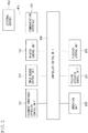
- Fig. 1 is a diagram illustrating a configuration of an image forming apparatus according to a first exemplary embodiment of the present invention.
- the image forming apparatus of the present exemplary embodiment includes an image forming apparatus main body constituted of an image reader 200 and a printer unit 300, a folding apparatus 500, and a finisher 600.
- a document conveyance apparatus 100 is mounted on the top of the image reader 200.
- An inserter 700 is provided on the top of the finisher 600.
- the image forming apparatus is constructed to be capable of communicating with a server apparatus 453 through a communication control unit 450 described below and acquires a packet for controlling start processing described below.
- the document conveyance apparatus 100 feeds document papers set on a document tray 105 one by one from a head page and carries the papers onto a document positioning glass plate via a curved path.
- Two reading modes are available for reading a one-sided original document.
- first reading mode a rear end of the original document is fed to and stopped at a reading position R1 on the document positioning glass plate 205, and a scanner unit 206 is moved from the left to the right to read the document.
- second reading mode an original document is carried up to the reading position R1 at a specific reading speed, and the original document is read with the scanner unit 206 fixed at the reading position R1.
- the original document is discharged onto a discharge tray 106.
- the front surface of the original document is read by the scanner unit 206 and the rear surface is read by an optical unit 110 arranged inside the document conveyance apparatus 100.
- An image sensor and a light source are arranged inside the optical unit 110.
- An image of an original document read by the image sensor 208 via the lens 207 is sent to an exposure control unit 305 via a printer control unit 301.
- the exposure control unit 305 outputs laser beam corresponding to an image signal.
- a photosensitive drum 306 is irradiated with the laser beam to form an electrostatic latent image on the photosensitive drum 306.
- the electrostatic latent image on the photosensitive drum 306 is developed by a developing device 307 and developer existing on the photosensitive drum 306 is transferred onto a sheet carried from any one of cassettes 308, 309, a manual feed unit 310, and a two-sided conveyance path 311, at a transfer unit 312.
- the sheet After developer is transferred onto the sheet, the sheet is guided to a fixing unit 313, in which fixing processing of the developer is executed. After passing the fixing unit 313, the sheet is guided to a path 314 from a path 315 by a flapper (not shown) . After the rear end of the sheet passes the path 315, the sheet is switched back and guided to discharge rollers 317. Consequently, with a surface to which the developer adheres, facing downward (face down status), the sheet can be discharged from the printer unit 300 by the discharge rollers 317. This is called inversed discharge. Because the sheet is discharged with its face down, when printing images read from a plurality of original documents by the document conveyance apparatus 100, the images can be formed in a right order from the head page.
- the sheet When forming an image on a hard sheet like an OHP sheet supplied through the manual feed unit 310, the sheet is not guided to the path 315 but is discharged through the discharge rollers 317 with a surface to which the developer adheres, facing upward (face up status).
- the sheet When forming an image on both surfaces of a sheet, the sheet is guided from the fixing unit 313 to the path 315 and the path 314. Just after the sheet passes the path 315, the sheet is switched back and guided to a two-sided conveyance path 311 by a flapper (not shown). An electrostatic latent image is transferred to the sheet guided onto the two-sided conveyance path 311 by the transfer unit 312 and the fixing processing is executed by the fixing unit 313.
- Setup of a path length, arrangement of rollers and division of a drive system enable conveyance of sheets even if five sheets of half size papers such as A4 size, B5 size exist on a path of a single circulation, from the transfer unit 312 via the two-sided conveyance path 311, back to the transfer unit 312 again. Because the sheets are discharged with their odd-pages facing downward, the sheet pages can be arranged in a proper order at the time of two-sided copy.
- the sheets discharged from the discharge rollers 317 are fed into the folding apparatus 500.
- the folding apparatus 500 executes a processing of folding the sheet into Z-shape.
- folding processing is specified for a sheet of A3 size or B4 size
- the sheet is fed into the finisher 600.
- Sheets of other sizes are fed into the finisher 600 without any treatment.
- the finisher 600 executes bookbinding processing, stapling processing and perforating processing.
- An inserter 700 is mounted on the top of the finisher 600 to supply a cover and an interleaf.
- a controller control unit 400 communicates with the image reader 200, the printer 300, the folding apparatus 500, and the finisher 600 to control the entire image forming apparatus.
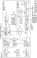
- Fig. 2 is a block diagram illustrating the entire configuration of the control unit of the image forming apparatus illustrated in Fig. 1 . This apparatus is constructed around the controller control unit 400 configured to control the entire image forming apparatus.
- the controller control unit 400 has a document conveyance apparatus control unit 101 configured to control the document conveyance apparatus 100 according to a setting of the operation unit 800 or an instruction from the server apparatus 453.
- the controller control unit 400 communicates with an image reader control unit 201 configured to control the image reader 200 to obtain image data of an input original document.
- the controller control unit 201 communicates with a printer control unit 301 configured to control the printer 300 and prints the image data on a sheet.
- the controller control unit 201 communicates with a folding apparatus control unit 501 configured to control the folding apparatus 500 and a finisher control unit 601 configured to control the finisher 600 to achieve desired outputs such as stapling printed sheets and punch-out of holes.
- a communication interface 451 is an interface 4 configured to connect the server apparatus 453 with the controller control unit, for example, through an external bus 452 such as a network and USB to rasterize print data supplied from the server apparatus 453 and output the processed data.
- Fig. 3 is a block diagram illustrating the configuration of the controller control unit illustrated in Fig. 2 .
- the controller control unit 400 is controlled by a CPU 401 within a main control unit 410 and is controlled by an operating system (hereinafter referred to OS).
- a bus bridge 408 is connected to a ROM 403 which stores an initial start program of the CPU 401 and a main storage memory (main memory) 405 which stores control data of the CPU 401 temporarily and is used as a work area for calculation accompanying a control.
- a storage unit 402 stores a main program including the operating system of the CPU 401.
- the storage unit 402 is also used as a temporary storage area for image data when the image forming apparatus of the present exemplary embodiment is activated.
- the communication control unit 450 configured to control a network and a USB interface and an operation portion control unit 406 configured to control the operation unit 800 are connected to the CPU 401.
- the CPU 401 communicates with a device control unit 407 through the bus bridge 408.
- the device control unit 407 is connected to the document conveyance apparatus control unit 101, the image reader control unit 201, the printer control unit 301, the folding apparatus control unit 501, and the finisher control unit 601 to control those components.
- a power supply control unit 418 controls power of the entire image forming apparatus. More specifically, the power supply control unit 418 controls power for the document conveyance apparatus control unit 101, the image reader control unit 201, the printer control unit 301, the folding apparatus control unit 501 and the finisher control unit 601 and performs power control in an energy saving mode within the controller control unit 400.
- a first power supply ON/OFF switching device 412 switches ON/OFF a first power supply 411 for supplying power to the communication control unit 450.
- a second power supply ON/OFF switching device 415 switches ON/OFF a second power supply 413 for supplying power to the CPU 401, the storage unit 402, and the ROM 403 within the controller control unit 400.
- a third power supply ON/OFF switching device 417 switches ON/OFF a third power supply 416 for supplying power to the main storage memory 405 within the controller control unit 400.
- the communication control unit 450 is connected to the first power supply ON/OFF switching device 412 to assess a packet received through the communication interface 451 and control a flag register 414.
- a main switch 420 notifies the power supply control unit 418 that the system has been operated directly by a user.
- the main switch 420 instructs the power supply control unit 418 to turn on power.
- the CPU 401 executes control to bring the image forming apparatus from the quick start condition to an idle condition according to a procedure illustrated in Figs. 6 and 7 .
- the power supply control unit 418 permits supply of power from the first to third power supplies in the idle condition described in detail below to bring the image forming apparatus into a state allowing formation of images.
- Fig. 4 is a diagram illustrating the configuration of the operation unit 800 of the image forming apparatus illustrated in Fig. 2 .
- a touch panel sheet is attached to its LCD panel.
- the touch panel sheet displays an operation screen for the system, and when a displayed key is pressed by a user, the operation unit 800 notifies the controller control unit 400 of its position information.
- a ten key keypad 801 is used for entering numbers like a number of copies.
- a start key 802 is used for starting copy operation or document reading operation after a user sets a desired condition.
- a stop key 803 is used for stopping an operation being currently carried out.
- An energy saving key 804 is used for transition to energy saving mode or return to the energy saving mode.
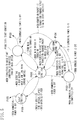
- FIG. 5 is a diagram illustrating a condition transition of the power supply of the image forming apparatus according to the exemplary embodiment.
- the system is brought to the shut-down condition (P104) .
- the power supply control unit 418 is powered on.
- the power supply control unit 418 switches ON the first power supply ON/OFF switching device 412. Consequently, the communication control unit 450 starts to receive a remote ON packet from the server apparatus 453.
- the image forming apparatus is brought to the quick start condition (P102) .
- the CPU 401 Upon receiving a power OFF instruction from the main switch 420 in the quick start condition, the CPU 401 brings the image forming apparatus from the idle condition to the quick start condition.
- the power supply control unit 418 turns ON the third power supply ON/OFF switching device 417, so that, in the main control unit 410, only the main storage memory 405 and the power supply control unit 418 are powered on.
- the image forming apparatus is brought to the idle condition (P100).
- the image forming apparatus is brought from the quick start condition to the idle condition.
- the first power supply ON/OFF switching device 412, the second power supply ON/OFF switching device 415, and the third power supply ON/OFF switching device 417 all remain ON.
- the operation portion control unit 406 and the device control unit 407 are also powered on so that the image forming apparatus is entirely activated.
- the image forming apparatus When a predetermined time set in the image forming apparatus elapses in the idle condition (P100), the image forming apparatus is brought to a sleep condition (P101). In this condition, although the first power supply ON/OFF switching device 412 and the third power supply ON/OFF switching device 417 are kept ON, the entire system except the main storage memory 405 within the controller control unit 400 is kept OFF.
- the communication control unit 450 determines whether a packet acquired by the communication control unit 450is a packet for activating the image forming apparatus main body in the idle condition which allows formation of an image, or a packet for activating the image forming apparatus main body in the quick start condition which restricts any operation except supplying power to the main memory.
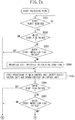
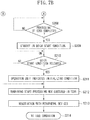
- Fig. 6 is a flow chart describing a control method of the image forming apparatus of the present exemplary embodiment.
- This example is start processing when the image forming apparatus receives from the server a command packet to stand by in the quick start condition.
- each step is processed by the power supply control unit 418 and the CPU 401 cooperating with each other.
- the CPU 401 loads a control program from the ROM 403 to the main storage memory 405 and executes the control program to achieve the processing of each step.
- start control for bringing the image forming apparatus from the idle condition to the quick start condition is performed as described below.
- the apparatus is in a condition (P104) in which only the power supply control unit 418 and the communication control unit 450 of the image forming apparatus are supplied with electric power.
- the communication control unit 450 within the controller control unit 400 determines whether the start packet has been received from the server apparatus 453.
- step S101 the communication control unit 450 determines whether the packet is a command packet to stand by in the quick start condition. If so, a quick start flag is raised in the flag resistor 414 and the processing proceeds to step S104. On the other hand, in step S102, if the communication control unit 450 determines that the received packet is not a command packet to stand by in the quick start condition, in step S103, the CPU 401 makes an indication for notifying a user that the operation unit 800 is being initialized.
- step S104 the power supply control unit 418 turns ON the second power supply ON/OFF switching device 415 and the third power supply ON/OFF switching device 417.
- step S104 the CPU 401 executes start processing of the controller control unit 400 except the device control unit 407 and the operation portion control unit 406.
- step S105 the CPU 401 determines whether the quick start flag has been raised at the time of the start processing of step S104.
- the CPU 401 determines that the quick start flag has been raised, after the processing of step S104 is completed in step S104, in step S107, the system stands by in the quick start condition.
- the power supply control unit 418 turns OFF the second power supply ON/OFF switching device 415 and the first power supply ON/OFF switching device 412.
- the third power supply ON/OFF switching device 417 is turned ON, so that the main storage memory 405 holds data. Then, when a user turns ON the main switch 420, the image forming apparatus is started quickly.
- step S105 the CPU 401 determines that no quick start flag has been raised
- step S104 the system enters into a flow (S110) for the remaining start processing, which is not executed in step S104.
- step S108 the CPU 401 releases energy saving mode and, in step S109, the CPU 401 displays an indication notifying a user that initialization of the operation unit 800 is being executed.
- step S110 the CPU 401 executes the remaining start processing of the device control unit 407, which is not executed in the start processing of step S104.
- This processing includes any source which generates vibration or impact, for example, a motor and a solenoid necessary for carrying an original document and a sheet or necessary for forming an image.
- step Sill a negotiation between the controller control unit 400 and peripheral devices is executed.
- the controller control unit 400 acquires information of the peripheral devices and checks to see whether communication is carried out properly.
- step S112 the above-described processing is finished, so that the start processing of the image forming apparatus is completed bringing the image forming apparatus into an idle condition. Consequently, the startup step of the image forming apparatus after the power is turned on by remote control, can be determined depending on the kind of a packet sent from the server apparatus. As a result, standby electric power of the image forming apparatus which is not consumed immediately can be suppressed. Further, the startup step of the image forming apparatus can be changed depending on a regular condition set by a user. As a consequence, the image forming apparatus can be started in the regular setting made by the user.
- the quick start processing when a packet for the quick start is received, the quick start processing is always executed.
- start processing may not be desired depending on a user's environment where the image forming apparatus is shared among users. Therefore, even if the aforementioned packet is received, if a setting for disenabling the packet is made in advance through the operation unit 800, the image forming apparatus may be started without executing the quick start processing.
- this exemplary embodiment will be described in detail.
- Fig. 7 is a flow chart describing a control method of the image forming apparatus according to a second exemplary embodiment of the present invention.
- This is start processing example when the image forming apparatus receives an instruction packet to stand by in the quick start condition, from the server.
- each step is processed by the power supply control unit 418 and the CPU 401 cooperating with each other.
- the CPU 401 achieves control by loading a control program to the main storage memory 405 and executing it. Start control will be described below which brings the image forming apparatus into the idle condition or the quick start condition by determining an enabled or disenabled state of the setting for restricting the quick start processing, according to a packet acquired from the server apparatus 453.
- step S201 the communication control unit 450 within the controller control unit 400 is in the standby condition waiting for a start packet sent from the server apparatus 453.
- the communication control unit 450 determines whether the packet is a command packet to stand by in the quick start condition. If so, in step S202, the communication control unit 450 raises the quick start flag on a flag register 414 and the processing proceeds to step S205.
- step S202 if the communication control unit 450 determines that no quick start flag has been raised, in step S203, the communication control unit 450 determines whether a quick start inhibition flag for the setting of the image forming apparatus to inhibit the quick start has been raised.
- the quick start is carried out together with electricity supply to the main storage memory 405 when the main switch 420 is turned OFF.
- the quick start inhibition may be set when a user desires to inhibit the electricity supply. If the CPU 401 determines that the quick start inhibition flag has been raised on the main storage memory 405, the processing proceeds to step S204. If the CPU 401 determines that no quick start inhibition flag has been raised, the processing proceeds to step S205. In step S204, the CPU 401 makes an indication to notify a user that initialization of the operation unit 800 is being executed.
- step S205 the power supply control unit 418 turns ON the second power supply ON/OFF switching device 415 and the third power supply ON/OFF switching device 417, and the CPU 401 executes the start processing of the controller control unit except the device control unit 407 and the operation portion control unit 406.
- step S205 the CPU 401 determines whether the quick start flag and the quick start inhibition flag have been raised in steps S206 and S207 respectively. If the quick start flag is ON and the quick start inhibition flag is OFF, in step S208, the system stands by for completion of the processing of step S205. Then, after the processing of step S205 is completed, in step S209, the CPU 401 stands by in the quick start condition.
- the power supply control unit 418 turns OFF the second power supply ON/OFF switching device 415 and the first power supply ON/OFF switching device 412.
- the third power supply ON/OFF switching device 417 is turned ON, data of the main storage memory 405 is held, so that when a user turns ON the main switch 420, the image forming apparatus is rapidly started.
- step S210 the CPU 401 determines whether releasing of the quick start condition has been instructed when the main switch 420 is turned ON.
- step S211 the CPU 401 makes an indication to inform a user that initialization of the operation unit 800 is being executed.
- step S212 when the CPU 401 determines that the quick start flag is OFF or the quick start inhibition flag is ON in steps S206 and S207 respectively, in step S212, the system enters into a flow of the remaining start processing, which is not executed in step S205 after step S205. More specifically, the system executes the remaining start processing of the device control unit 407 not executed in the start processing of step S205.
- This processing includes a source which generates vibration or impact, for example, a motor and a solenoid necessary for carrying an original document and a sheet or necessary for forming an image.
- step S213 a negotiation between the controller control unit 400 and peripheral devices is executed.
- the controller control unit 400 acquires information of the peripheral devices and checks to see whether communication is executed properly.
- step S214 the start processing of the image forming apparatus is completed, so that the image forming apparatus is brought into the idle condition.
- the image forming apparatus may execute start processing convenient to a user.
- the respective steps of the present invention may be achieved by a processing apparatus (CPU, processor) of a personal computer executing software (program) acquired through a network or a variety of storage mediums.
- a processing apparatus CPU, processor
- software program
- the system upon receiving the start packet, the system is brought from a shutdown condition (P104) to the quick start condition (P103), the present invention is not restricted to this example.
- the system upon receiving a specific packet, the system may be brought from the shutdown condition (P104) to a sleep condition (P101).
- the aforementioned specific packet is transmitted from the server apparatus 453 to start the image forming apparatus.
- This specific packet is different from the packet for causing the image forming apparatus to execute a specific processing (e.g., print processing, scan processing, data storage processing to an HDD).
- the specific packet transmitted from this server apparatus 453 is a broadcast packet or a multicast packet.
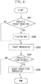
- FIG. 8 An operation of the image forming apparatus of this modification will be described with reference to Fig. 8 .
- the image forming apparatus of this modification is in the shutdown condition in which only the power supply control unit 418 and the communication control unit 450 are supplied with electricity.
- the communication control unit 450 in the controller control unit 400 is in the standby condition for a specific packet sent from the server apparatus 453.
- step S301 the communication control unit 450 determines whether the specific packet has been received.
- the communication control unit 450 determines that any specific packet has been received (YES in step S301)
- the communication control unit 450 raises a flag indicating that the specific packet has been received on the flag register 414.
- the communication control unit 450 determines that other packet than the specific packet has been received (NO in step S301), the communication control unit 450proceeds with the processing without raising the aforementioned flag on the flag register 414.
- the power supply control unit 418 turns ON the second power supply ON/OFF switching device 415 and the third power supply ON/OFF switching device 417. Consequently, the main control unit 410 of the CPU 401 is supplied with electricity. Then, in step S303, the CPU 401 executes the start processing of the main control unit 410. As a result, the power condition of the image forming apparatus turns into the idle condition (P100).
- step S304 the power supply control unit 418 determines whether the specific flag is raised on the flag register 414.
- step S305 the CPU 401 executes the sleep transition processing. More specifically, the power supply control unit 418 turns OFF the second power supply ON/OFF switching device 415 and the third power supply ON/OFF switching device 417. Consequently, a supply of electricity to the controller control unit 400 is interrupted. As a result, the power condition of the image forming apparatus turns into the sleep condition (P101).
- the above-described modification indicates a shutdown condition in which only the power supply control unit 418 and the communication control unit 450 are supplied with electricity.
- this modification when a specific packet is received from the server apparatus, the power condition of the image forming apparatus is brought into the sleep condition, and when other packet than the specific packet is received from the server apparatus, the power condition of the image forming apparatus is brought into the idle condition.
- the above modification is not restricted to the sleep condition as long as the power condition of the image forming apparatus is brought from the idle condition to the energy saving condition.
- aspects of the present invention can also be realized by a computer of a system or apparatus (or devices such as a CPU or MPU) that reads out and executes a program recorded on a memory device to perform the functions of the above-described embodiment (s), and by a method, the steps of which are performed by a computer of a system or apparatus by, for example, reading out and executing a program recorded on a memory device to perform the functions of the above-described embodiment(s).
- the program is provided to the computer for example via a network or from a recording medium of various types serving as the memory device (e.g., computer-readable medium).
Landscapes
- Engineering & Computer Science (AREA)
- Theoretical Computer Science (AREA)
- Physics & Mathematics (AREA)
- General Physics & Mathematics (AREA)
- General Engineering & Computer Science (AREA)
- Human Computer Interaction (AREA)
- Microelectronics & Electronic Packaging (AREA)
- Facsimiles In General (AREA)
- Accessory Devices And Overall Control Thereof (AREA)
- Control Or Security For Electrophotography (AREA)
- Power Sources (AREA)
Applications Claiming Priority (1)
| Application Number | Priority Date | Filing Date | Title |
|---|---|---|---|
| JP2011123476A JP6025307B2 (ja) | 2011-06-01 | 2011-06-01 | 画像形成装置、画像形成装置の制御方法、及びプログラム |
Publications (3)
| Publication Number | Publication Date |
|---|---|
| EP2530529A2 EP2530529A2 (en) | 2012-12-05 |
| EP2530529A3 EP2530529A3 (en) | 2017-08-23 |
| EP2530529B1 true EP2530529B1 (en) | 2020-12-23 |
Family
ID=46465014
Family Applications (1)
| Application Number | Title | Priority Date | Filing Date |
|---|---|---|---|
| EP12169877.3A Active EP2530529B1 (en) | 2011-06-01 | 2012-05-29 | Image forming apparatus, control method of image forming apparatus and storage medium |
Country Status (5)
| Country | Link |
|---|---|
| US (2) | US8842318B2 (ja) |
| EP (1) | EP2530529B1 (ja) |
| JP (1) | JP6025307B2 (ja) |
| KR (1) | KR101530556B1 (ja) |
| CN (1) | CN102811295B (ja) |
Families Citing this family (3)
| Publication number | Priority date | Publication date | Assignee | Title |
|---|---|---|---|---|
| JP2014075786A (ja) * | 2012-09-11 | 2014-04-24 | Canon Inc | 画像形成装置、画像形成装置の制御方法、及び、プログラム |
| JP6249741B2 (ja) | 2013-11-29 | 2017-12-20 | キヤノン株式会社 | 情報処理装置、及び情報処理装置の制御方法 |
| WO2017078709A1 (en) * | 2015-11-04 | 2017-05-11 | Intel Corporation | Three-dimensional small form factor system in package architecture |
Family Cites Families (9)
| Publication number | Priority date | Publication date | Assignee | Title |
|---|---|---|---|---|
| KR100316647B1 (ko) | 1998-07-30 | 2002-01-15 | 윤종용 | 웨이크 온 랜신호를 이용한 컴퓨터 시스템에서의 파워 제어방법및 그 장치 |
| JP2003248580A (ja) * | 2002-02-22 | 2003-09-05 | Seiko Epson Corp | プログラムおよび情報処理装置 |
| JP4250396B2 (ja) * | 2002-10-08 | 2009-04-08 | キヤノン株式会社 | 画像形成装置 |
| JP2005335106A (ja) * | 2004-05-25 | 2005-12-08 | Matsushita Electric Ind Co Ltd | 印刷装置および印刷装置の制御方法 |
| KR100554196B1 (ko) * | 2005-11-22 | 2006-02-24 | 김동현 | 네트워크 프린터의 문서 출력 방법 |
| JP4871598B2 (ja) * | 2006-01-19 | 2012-02-08 | キヤノン株式会社 | 画像処理装置および画像処理装置の起動方法およびプログラム |
| JP4587985B2 (ja) * | 2006-04-10 | 2010-11-24 | シャープ株式会社 | 画像処理装置 |
| JP5414329B2 (ja) * | 2009-03-31 | 2014-02-12 | 京セラドキュメントソリューションズ株式会社 | 画像形成装置 |
| JP5287494B2 (ja) * | 2009-05-20 | 2013-09-11 | 株式会社リコー | 画像処理装置 |
-
2011
- 2011-06-01 JP JP2011123476A patent/JP6025307B2/ja not_active Expired - Fee Related
-
2012
- 2012-05-29 EP EP12169877.3A patent/EP2530529B1/en active Active
- 2012-05-29 US US13/482,677 patent/US8842318B2/en not_active Expired - Fee Related
- 2012-05-30 CN CN201210179287.XA patent/CN102811295B/zh not_active Expired - Fee Related
- 2012-05-30 KR KR1020120057129A patent/KR101530556B1/ko active IP Right Grant
-
2014
- 2014-09-05 US US14/479,168 patent/US9245218B2/en active Active
Non-Patent Citations (1)
| Title |
|---|
| None * |
Also Published As
| Publication number | Publication date |
|---|---|
| JP2012252454A (ja) | 2012-12-20 |
| CN102811295A (zh) | 2012-12-05 |
| US8842318B2 (en) | 2014-09-23 |
| US20150022858A1 (en) | 2015-01-22 |
| EP2530529A3 (en) | 2017-08-23 |
| US20120307285A1 (en) | 2012-12-06 |
| CN102811295B (zh) | 2015-09-09 |
| US9245218B2 (en) | 2016-01-26 |
| KR101530556B1 (ko) | 2015-06-22 |
| JP6025307B2 (ja) | 2016-11-16 |
| EP2530529A2 (en) | 2012-12-05 |
| KR20120135059A (ko) | 2012-12-12 |
Similar Documents
| Publication | Publication Date | Title |
|---|---|---|
| US9041949B2 (en) | Image forming apparatus, control method of image forming apparatus, and computer-readable storage medium | |
| JP5847501B2 (ja) | 情報処理装置、その制御方法、およびプログラム、並びに記録媒体 | |
| US20110116128A1 (en) | Image forming system which includes image processing device and plural image forming devices | |
| KR20090129962A (ko) | 화상 형성 장치 | |
| US9245218B2 (en) | Image forming apparatus, control method of image forming apparatus and storage medium | |
| JP2002296983A (ja) | 画像処理装置 | |
| JP4574441B2 (ja) | 画像形成装置及びその制御方法 | |
| US20140376033A1 (en) | Image formation system | |
| JP2015098096A (ja) | 画像形成装置および画像形成装置の制御方法 | |
| US8885198B2 (en) | Image forming apparatus, control method for image forming apparatus, and storage medium for performing power-saving control | |
| JP2002120443A (ja) | 画像形成装置 | |
| JP2008209825A (ja) | 画像形成装置、およびその制御プログラム | |
| JP2012237835A (ja) | 画像形成システム | |
| JP5687177B2 (ja) | 再起動装置及び再起動方法 | |
| JP4373747B2 (ja) | 画像形成システム | |
| KR101429851B1 (ko) | 화상 형성 장치 | |
| JP2015152846A (ja) | 画像形成装置、画像形成装置の電源制御方法、及びプログラム | |
| US20180343355A1 (en) | Image forming apparatus that uses a removable storage medium | |
| JP2015101064A (ja) | 画像形成システムの制御方法およびプログラム | |
| JP2024007685A (ja) | 画像形成装置、画像形成装置の制御方法、及びプログラム | |
| JP2023180342A (ja) | 画像形成装置、画像形成装置の制御方法 | |
| JP2015196255A (ja) | 画像形成装置 | |
| JP2013054423A (ja) | 画像形成装置、電源制御方法及びプログラム | |
| JP2013111755A (ja) | 画像形成装置、画像形成装置の制御方法、及びプログラム | |
| JP2017047643A (ja) | 画像形成装置の省電力および待機モードの状態遷移方法 |
Legal Events
| Date | Code | Title | Description |
|---|---|---|---|
| PUAI | Public reference made under article 153(3) epc to a published international application that has entered the european phase |
Free format text: ORIGINAL CODE: 0009012 |
|
| AK | Designated contracting states |
Kind code of ref document: A2 Designated state(s): AL AT BE BG CH CY CZ DE DK EE ES FI FR GB GR HR HU IE IS IT LI LT LU LV MC MK MT NL NO PL PT RO RS SE SI SK SM TR |
|
| AX | Request for extension of the european patent |
Extension state: BA ME |
|
| PUAL | Search report despatched |
Free format text: ORIGINAL CODE: 0009013 |
|
| AK | Designated contracting states |
Kind code of ref document: A3 Designated state(s): AL AT BE BG CH CY CZ DE DK EE ES FI FR GB GR HR HU IE IS IT LI LT LU LV MC MK MT NL NO PL PT RO RS SE SI SK SM TR |
|
| AX | Request for extension of the european patent |
Extension state: BA ME |
|
| RIC1 | Information provided on ipc code assigned before grant |
Ipc: G03G 15/00 20060101AFI20170718BHEP |
|
| STAA | Information on the status of an ep patent application or granted ep patent |
Free format text: STATUS: REQUEST FOR EXAMINATION WAS MADE |
|
| 17P | Request for examination filed |
Effective date: 20180223 |
|
| RBV | Designated contracting states (corrected) |
Designated state(s): AL AT BE BG CH CY CZ DE DK EE ES FI FR GB GR HR HU IE IS IT LI LT LU LV MC MK MT NL NO PL PT RO RS SE SI SK SM TR |
|
| GRAP | Despatch of communication of intention to grant a patent |
Free format text: ORIGINAL CODE: EPIDOSNIGR1 |
|
| STAA | Information on the status of an ep patent application or granted ep patent |
Free format text: STATUS: GRANT OF PATENT IS INTENDED |
|
| INTG | Intention to grant announced |
Effective date: 20200203 |
|
| GRAJ | Information related to disapproval of communication of intention to grant by the applicant or resumption of examination proceedings by the epo deleted |
Free format text: ORIGINAL CODE: EPIDOSDIGR1 |
|
| STAA | Information on the status of an ep patent application or granted ep patent |
Free format text: STATUS: REQUEST FOR EXAMINATION WAS MADE |
|
| GRAP | Despatch of communication of intention to grant a patent |
Free format text: ORIGINAL CODE: EPIDOSNIGR1 |
|
| STAA | Information on the status of an ep patent application or granted ep patent |
Free format text: STATUS: GRANT OF PATENT IS INTENDED |
|
| INTC | Intention to grant announced (deleted) | ||
| INTG | Intention to grant announced |
Effective date: 20200715 |
|
| GRAS | Grant fee paid |
Free format text: ORIGINAL CODE: EPIDOSNIGR3 |
|
| GRAA | (expected) grant |
Free format text: ORIGINAL CODE: 0009210 |
|
| STAA | Information on the status of an ep patent application or granted ep patent |
Free format text: STATUS: THE PATENT HAS BEEN GRANTED |
|
| AK | Designated contracting states |
Kind code of ref document: B1 Designated state(s): AL AT BE BG CH CY CZ DE DK EE ES FI FR GB GR HR HU IE IS IT LI LT LU LV MC MK MT NL NO PL PT RO RS SE SI SK SM TR |
|
| REG | Reference to a national code |
Ref country code: GB Ref legal event code: FG4D |
|
| REG | Reference to a national code |
Ref country code: DE Ref legal event code: R096 Ref document number: 602012073810 Country of ref document: DE |
|
| REG | Reference to a national code |
Ref country code: AT Ref legal event code: REF Ref document number: 1348317 Country of ref document: AT Kind code of ref document: T Effective date: 20210115 |
|
| REG | Reference to a national code |
Ref country code: IE Ref legal event code: FG4D |
|
| PG25 | Lapsed in a contracting state [announced via postgrant information from national office to epo] |
Ref country code: RS Free format text: LAPSE BECAUSE OF FAILURE TO SUBMIT A TRANSLATION OF THE DESCRIPTION OR TO PAY THE FEE WITHIN THE PRESCRIBED TIME-LIMIT Effective date: 20201223 Ref country code: FI Free format text: LAPSE BECAUSE OF FAILURE TO SUBMIT A TRANSLATION OF THE DESCRIPTION OR TO PAY THE FEE WITHIN THE PRESCRIBED TIME-LIMIT Effective date: 20201223 Ref country code: NO Free format text: LAPSE BECAUSE OF FAILURE TO SUBMIT A TRANSLATION OF THE DESCRIPTION OR TO PAY THE FEE WITHIN THE PRESCRIBED TIME-LIMIT Effective date: 20210323 Ref country code: GR Free format text: LAPSE BECAUSE OF FAILURE TO SUBMIT A TRANSLATION OF THE DESCRIPTION OR TO PAY THE FEE WITHIN THE PRESCRIBED TIME-LIMIT Effective date: 20210324 |
|
| REG | Reference to a national code |
Ref country code: AT Ref legal event code: MK05 Ref document number: 1348317 Country of ref document: AT Kind code of ref document: T Effective date: 20201223 |
|
| REG | Reference to a national code |
Ref country code: NL Ref legal event code: MP Effective date: 20201223 |
|
| PG25 | Lapsed in a contracting state [announced via postgrant information from national office to epo] |
Ref country code: SE Free format text: LAPSE BECAUSE OF FAILURE TO SUBMIT A TRANSLATION OF THE DESCRIPTION OR TO PAY THE FEE WITHIN THE PRESCRIBED TIME-LIMIT Effective date: 20201223 Ref country code: LV Free format text: LAPSE BECAUSE OF FAILURE TO SUBMIT A TRANSLATION OF THE DESCRIPTION OR TO PAY THE FEE WITHIN THE PRESCRIBED TIME-LIMIT Effective date: 20201223 Ref country code: BG Free format text: LAPSE BECAUSE OF FAILURE TO SUBMIT A TRANSLATION OF THE DESCRIPTION OR TO PAY THE FEE WITHIN THE PRESCRIBED TIME-LIMIT Effective date: 20210323 |
|
| PG25 | Lapsed in a contracting state [announced via postgrant information from national office to epo] |
Ref country code: HR Free format text: LAPSE BECAUSE OF FAILURE TO SUBMIT A TRANSLATION OF THE DESCRIPTION OR TO PAY THE FEE WITHIN THE PRESCRIBED TIME-LIMIT Effective date: 20201223 Ref country code: NL Free format text: LAPSE BECAUSE OF FAILURE TO SUBMIT A TRANSLATION OF THE DESCRIPTION OR TO PAY THE FEE WITHIN THE PRESCRIBED TIME-LIMIT Effective date: 20201223 |
|
| REG | Reference to a national code |
Ref country code: LT Ref legal event code: MG9D |
|
| PG25 | Lapsed in a contracting state [announced via postgrant information from national office to epo] |
Ref country code: SK Free format text: LAPSE BECAUSE OF FAILURE TO SUBMIT A TRANSLATION OF THE DESCRIPTION OR TO PAY THE FEE WITHIN THE PRESCRIBED TIME-LIMIT Effective date: 20201223 Ref country code: PT Free format text: LAPSE BECAUSE OF FAILURE TO SUBMIT A TRANSLATION OF THE DESCRIPTION OR TO PAY THE FEE WITHIN THE PRESCRIBED TIME-LIMIT Effective date: 20210423 Ref country code: RO Free format text: LAPSE BECAUSE OF FAILURE TO SUBMIT A TRANSLATION OF THE DESCRIPTION OR TO PAY THE FEE WITHIN THE PRESCRIBED TIME-LIMIT Effective date: 20201223 Ref country code: LT Free format text: LAPSE BECAUSE OF FAILURE TO SUBMIT A TRANSLATION OF THE DESCRIPTION OR TO PAY THE FEE WITHIN THE PRESCRIBED TIME-LIMIT Effective date: 20201223 Ref country code: SM Free format text: LAPSE BECAUSE OF FAILURE TO SUBMIT A TRANSLATION OF THE DESCRIPTION OR TO PAY THE FEE WITHIN THE PRESCRIBED TIME-LIMIT Effective date: 20201223 Ref country code: EE Free format text: LAPSE BECAUSE OF FAILURE TO SUBMIT A TRANSLATION OF THE DESCRIPTION OR TO PAY THE FEE WITHIN THE PRESCRIBED TIME-LIMIT Effective date: 20201223 Ref country code: CZ Free format text: LAPSE BECAUSE OF FAILURE TO SUBMIT A TRANSLATION OF THE DESCRIPTION OR TO PAY THE FEE WITHIN THE PRESCRIBED TIME-LIMIT Effective date: 20201223 |
|
| PGFP | Annual fee paid to national office [announced via postgrant information from national office to epo] |
Ref country code: DE Payment date: 20210421 Year of fee payment: 10 |
|
| PG25 | Lapsed in a contracting state [announced via postgrant information from national office to epo] |
Ref country code: AT Free format text: LAPSE BECAUSE OF FAILURE TO SUBMIT A TRANSLATION OF THE DESCRIPTION OR TO PAY THE FEE WITHIN THE PRESCRIBED TIME-LIMIT Effective date: 20201223 Ref country code: PL Free format text: LAPSE BECAUSE OF FAILURE TO SUBMIT A TRANSLATION OF THE DESCRIPTION OR TO PAY THE FEE WITHIN THE PRESCRIBED TIME-LIMIT Effective date: 20201223 |
|
| PGFP | Annual fee paid to national office [announced via postgrant information from national office to epo] |
Ref country code: GB Payment date: 20210422 Year of fee payment: 10 |
|
| REG | Reference to a national code |
Ref country code: DE Ref legal event code: R097 Ref document number: 602012073810 Country of ref document: DE |
|
| PG25 | Lapsed in a contracting state [announced via postgrant information from national office to epo] |
Ref country code: IS Free format text: LAPSE BECAUSE OF FAILURE TO SUBMIT A TRANSLATION OF THE DESCRIPTION OR TO PAY THE FEE WITHIN THE PRESCRIBED TIME-LIMIT Effective date: 20210423 |
|
| PG25 | Lapsed in a contracting state [announced via postgrant information from national office to epo] |
Ref country code: IT Free format text: LAPSE BECAUSE OF FAILURE TO SUBMIT A TRANSLATION OF THE DESCRIPTION OR TO PAY THE FEE WITHIN THE PRESCRIBED TIME-LIMIT Effective date: 20201223 Ref country code: AL Free format text: LAPSE BECAUSE OF FAILURE TO SUBMIT A TRANSLATION OF THE DESCRIPTION OR TO PAY THE FEE WITHIN THE PRESCRIBED TIME-LIMIT Effective date: 20201223 |
|
| PLBE | No opposition filed within time limit |
Free format text: ORIGINAL CODE: 0009261 |
|
| STAA | Information on the status of an ep patent application or granted ep patent |
Free format text: STATUS: NO OPPOSITION FILED WITHIN TIME LIMIT |
|
| PG25 | Lapsed in a contracting state [announced via postgrant information from national office to epo] |
Ref country code: ES Free format text: LAPSE BECAUSE OF FAILURE TO SUBMIT A TRANSLATION OF THE DESCRIPTION OR TO PAY THE FEE WITHIN THE PRESCRIBED TIME-LIMIT Effective date: 20201223 Ref country code: DK Free format text: LAPSE BECAUSE OF FAILURE TO SUBMIT A TRANSLATION OF THE DESCRIPTION OR TO PAY THE FEE WITHIN THE PRESCRIBED TIME-LIMIT Effective date: 20201223 |
|
| 26N | No opposition filed |
Effective date: 20210924 |
|
| REG | Reference to a national code |
Ref country code: CH Ref legal event code: PL |
|
| PG25 | Lapsed in a contracting state [announced via postgrant information from national office to epo] |
Ref country code: CH Free format text: LAPSE BECAUSE OF NON-PAYMENT OF DUE FEES Effective date: 20210531 Ref country code: LU Free format text: LAPSE BECAUSE OF NON-PAYMENT OF DUE FEES Effective date: 20210529 Ref country code: LI Free format text: LAPSE BECAUSE OF NON-PAYMENT OF DUE FEES Effective date: 20210531 Ref country code: MC Free format text: LAPSE BECAUSE OF FAILURE TO SUBMIT A TRANSLATION OF THE DESCRIPTION OR TO PAY THE FEE WITHIN THE PRESCRIBED TIME-LIMIT Effective date: 20201223 |
|
| REG | Reference to a national code |
Ref country code: BE Ref legal event code: MM Effective date: 20210531 |
|
| PG25 | Lapsed in a contracting state [announced via postgrant information from national office to epo] |
Ref country code: SI Free format text: LAPSE BECAUSE OF FAILURE TO SUBMIT A TRANSLATION OF THE DESCRIPTION OR TO PAY THE FEE WITHIN THE PRESCRIBED TIME-LIMIT Effective date: 20201223 |
|
| PG25 | Lapsed in a contracting state [announced via postgrant information from national office to epo] |
Ref country code: IE Free format text: LAPSE BECAUSE OF NON-PAYMENT OF DUE FEES Effective date: 20210529 |
|
| PG25 | Lapsed in a contracting state [announced via postgrant information from national office to epo] |
Ref country code: IS Free format text: LAPSE BECAUSE OF FAILURE TO SUBMIT A TRANSLATION OF THE DESCRIPTION OR TO PAY THE FEE WITHIN THE PRESCRIBED TIME-LIMIT Effective date: 20210423 Ref country code: FR Free format text: LAPSE BECAUSE OF NON-PAYMENT OF DUE FEES Effective date: 20210531 |
|
| PG25 | Lapsed in a contracting state [announced via postgrant information from national office to epo] |
Ref country code: BE Free format text: LAPSE BECAUSE OF NON-PAYMENT OF DUE FEES Effective date: 20210531 |
|
| REG | Reference to a national code |
Ref country code: DE Ref legal event code: R119 Ref document number: 602012073810 Country of ref document: DE |
|
| GBPC | Gb: european patent ceased through non-payment of renewal fee |
Effective date: 20220529 |
|
| PG25 | Lapsed in a contracting state [announced via postgrant information from national office to epo] |
Ref country code: HU Free format text: LAPSE BECAUSE OF FAILURE TO SUBMIT A TRANSLATION OF THE DESCRIPTION OR TO PAY THE FEE WITHIN THE PRESCRIBED TIME-LIMIT; INVALID AB INITIO Effective date: 20120529 Ref country code: GB Free format text: LAPSE BECAUSE OF NON-PAYMENT OF DUE FEES Effective date: 20220529 Ref country code: DE Free format text: LAPSE BECAUSE OF NON-PAYMENT OF DUE FEES Effective date: 20221201 Ref country code: CY Free format text: LAPSE BECAUSE OF FAILURE TO SUBMIT A TRANSLATION OF THE DESCRIPTION OR TO PAY THE FEE WITHIN THE PRESCRIBED TIME-LIMIT Effective date: 20201223 |
|
| PG25 | Lapsed in a contracting state [announced via postgrant information from national office to epo] |
Ref country code: MK Free format text: LAPSE BECAUSE OF FAILURE TO SUBMIT A TRANSLATION OF THE DESCRIPTION OR TO PAY THE FEE WITHIN THE PRESCRIBED TIME-LIMIT Effective date: 20201223 |