EP2524779A1 - Hand-Werkzeugmaschine mit einem beweglichen Verstellanschlag - Google Patents
Hand-Werkzeugmaschine mit einem beweglichen Verstellanschlag Download PDFInfo
- Publication number
- EP2524779A1 EP2524779A1 EP12003012A EP12003012A EP2524779A1 EP 2524779 A1 EP2524779 A1 EP 2524779A1 EP 12003012 A EP12003012 A EP 12003012A EP 12003012 A EP12003012 A EP 12003012A EP 2524779 A1 EP2524779 A1 EP 2524779A1
- Authority
- EP
- European Patent Office
- Prior art keywords
- stop
- latching
- machine tool
- adjustment
- tool according
- Prior art date
- Legal status (The legal status is an assumption and is not a legal conclusion. Google has not performed a legal analysis and makes no representation as to the accuracy of the status listed.)
- Granted
Links
Images


Classifications
-
- B—PERFORMING OPERATIONS; TRANSPORTING
- B27—WORKING OR PRESERVING WOOD OR SIMILAR MATERIAL; NAILING OR STAPLING MACHINES IN GENERAL
- B27F—DOVETAILED WORK; TENONS; SLOTTING MACHINES FOR WOOD OR SIMILAR MATERIAL; NAILING OR STAPLING MACHINES
- B27F5/00—Slotted or mortised work
- B27F5/02—Slotting or mortising machines tools therefor
- B27F5/023—Portable plate joiners
-
- B—PERFORMING OPERATIONS; TRANSPORTING
- B27—WORKING OR PRESERVING WOOD OR SIMILAR MATERIAL; NAILING OR STAPLING MACHINES IN GENERAL
- B27C—PLANING, DRILLING, MILLING, TURNING OR UNIVERSAL MACHINES FOR WOOD OR SIMILAR MATERIAL
- B27C3/00—Drilling machines or drilling devices; Equipment therefor
- B27C3/06—Drilling machines or devices for making dowel holes
-
- B—PERFORMING OPERATIONS; TRANSPORTING
- B27—WORKING OR PRESERVING WOOD OR SIMILAR MATERIAL; NAILING OR STAPLING MACHINES IN GENERAL
- B27C—PLANING, DRILLING, MILLING, TURNING OR UNIVERSAL MACHINES FOR WOOD OR SIMILAR MATERIAL
- B27C3/00—Drilling machines or drilling devices; Equipment therefor
- B27C3/08—Operator-supported drilling machines or devices
Definitions
- the invention relates to a hand-held machine tool, in particular dowel milling machine, with at least one cutting tool for drilling and / or milling a recess in a workpiece front side of a workpiece, with a stop device for abutment against the workpiece, which has a front stop surface, and at least one in a transverse distance to the tool arranged adjustment stop, which is movably mounted between a stop position in which the adjustment stop protrudes in front of the front stop surface and a rest position in which the at least one adjustment stop does not project in front of the front stop surface or behind the front stop surface is moved back.
- Such a hand-held machine tool is for example off DE 10 2008 008 890 A1 known.
- the adjustment stops are pivotally mounted in this known dowel cutter on a stop device, so that they can be pivoted before the front stop surface of the stop device before, but also behind the front stop surface back, so that they are inactive.
- the adjustment stops form transverse stops.
- a disadvantage of the known, latch-like Verstellanellen is that they only cumbersome, for example by means of a screw or clamp, in their inactive, behind the Front stop surface can be set back pivoted position. The handling is cumbersome.
- a hand-held machine tool of the type mentioned that it has a locking device for locking the at least one Verstellanschlags in at least one position of the at least one Verstellanschlags relative to the front stop surface.
- the at least one cutting tool protrudes in front of the front abutment surface of the stop device of the hand-held machine tool or is adjustable in front of the front abutment surface, e.g. by means of a guide arrangement.
- the stop means may e.g. have a plurality of stop surfaces, that is, the front stop surface and at least one second stop surface.
- the cutting tool is arranged on the second stop surface and before this is adjustable or protruding in front of them. It is possible that at the front stop surface and / or at the at least one second at least one before the respective stop surface before adjustable and latchable by means of a locking device in the context of the invention adjustable stop.
- the adjustment stop only or in the stop position in which the adjustment stop is quasi active, can be locked.
- the adjustment stop is not movable transversely to its axis of movement or movement curve, along which it is adjustable in front of or behind the front stop surface before or behind.
- the at least one adjustment stop is configured for transverse abutment against a workpiece transverse side which is angled toward the workpiece front side, so that a transverse distance between the recess to be milled or the hole to be drilled and the workpiece lateral side can be adjusted with the adjustment stop ,
- a particularly preferred embodiment of the invention provides that the latching device with respect to the rest position only comes into latching engagement with the at least one adjustment stop when a front end of the at least one adjustment stop is moved back behind the front stop surface, so that the at least one adjustment stop at a position in which its front end face is flush with the front stop surface, not or not yet latched.
- a basic idea is that, for example, a workpiece bearing on the front abutment surface, in any case a plane surface which loads the adjustment stop in the direction of the rest position, can displace the at least one adjustment stop in the direction of the rest position but does not latch it.
- the at least one adjustment stop remains movable and can be actuated, for example, by the workpiece, without locking with or in the stop device.
- a plurality, i. at least two, adjustable stops are present.
- a variant provides that on both sides of the cutting tool in each case at least one adjustment stop is arranged.
- one stop can be brought into contact with the workpiece on the right and left of the cutting tool.
- two adjusting stops arranged at a first and at a second distance are provided on one side of the cutting tool, so that with respect to the cutting tool or a central axis of the cutting tool different transverse distances between the respective adjustment stop and the recess to be drilled or milled are adjustable.
- the front end faces of the at least one or the Verstellanelle and the cutting tool are arranged approximately along an axis line.
- the axis line forms, for example, a row axis, along which at least one adjustment stop and the cutting tool or a plurality of adjustment stops are arranged side by side.
- the cutting tool is expediently arranged between a first and at least one second adjustment stop.
- two or more Verstellanoeuvre can be provided on both sides of the milling tool in each case.
- the distances between a milling tool and a respective Verstellanschlag, one of which is arranged on one side, another on an opposite side of the milling tool, may be the same or different. So it is also possible an asymmetric spacing of Verstellanangen to milling tools.
- a plurality of milling tools for example juxtaposed drills, milling cutters and the like, are also possible.
- the invention can also be used in multi-spindle drills, biscuit milling or the like.
- the hand-held machine tool has a release device for releasing the latching of the latching device.
- the locking device engages in or on the adjustment stop, but can only be solved by pressing the release device. But it is also a locking engagement conceivable, which is solvable by a second operation of the adjustment stop, for example, as in a ballpoint pen.
- the latching device comprises a heart cam, so that the latching can be released beyond a latching position by means of a pressure actuation of the at least one adjusting stop.
- the adjustment stop must be pressed behind the front stop surface to get out of the catch free.
- the release device is expediently for releasing the locking of several, for example at least two, adjustment stops designed.
- a single operation for example, an axial displacement and / or a rotation of the release device, not only a Verstellanschlag, but it can be solved simultaneously several Verstellanoeuvre from the catch.
- the release device advantageously comprises a support on which at least one latching projection, preferably two latching projections, for latching with the at least one adjustment stop is present, and that the carrier relative to the stop device of the hand-held machine tool between a release position and a holding position movable, in particular slidingly mounted is.
- the at least one latching projection is adjusted relative to the at least one adjustment stop in the holding position so that the at least one adjustment stop can engage in detent engagement with the at least one latching projection.
- the at least one latching projection is displaced relative to the at least one adjustment stop or moved away from the at least one adjustment stop such that the at least one latching projection and the at least one adjustment stop can not engage or are disengaged. So if the carrier is in the release position, a locking of the Verstellanoeuvre with the respective associated locking projection is not possible or is solved.
- the at least one adjustment stop is loaded by a release spring arrangement in the direction of the stop position.
- the spring arrangement comprises, for example, at least one coil spring and / or at least one spring tongue or the like.
- the spring assembly pushes the respective Verstellanschlag before the front stop surface, so that an additional operator intervention is not necessary.
- a particularly simple operation is possible, ie that the one or more adjustment stops are released by means of the release device from the latch and then automatically, namely by the spring load, moved forward in front of the front stop surface before.
- the release device is loaded by a retaining spring arrangement in the sense of holding the latching of the latching device with the at least one adjustment stop.
- the retaining spring arrangement comprises, for example, at least one coil spring and / or at least one spring tongue or the like.
- each adjustment stop and / or the release device an individual spring, such as a spring tongue, coil spring or the like may be assigned. It is also possible that a Verstellanschlag or the release device comprises a resilient elastic portion as a spring or spring assembly.
- a preferred embodiment of the invention provides that the holding spring arrangement and the disengagement spring arrangement are at least partially formed by a one-piece spring body, which thus provides components of both spring arrangements.
- the spring body comprises, for example, a stamped and bent part, on which at least two spring tongues or spring projections are arranged, one of which or one a Verstellanschlag, while another spring tongue or another spring projection loads the release device, for example the carrier, are arranged on the locking projections.
- the adjustment stop for example, can be mounted slidingly with respect to the stop device or on the stop device. It is understood that a pivotable mounting is possible, which is still clear in the embodiment.
- the adjustment stop may be pivotally mounted in the manner of a pawl. It is understood that combined storage, i. a linear-movable and pivotable mounting, an adjustment stop is also possible.
- the stop device and the at least one adjustment stop expediently form a kind of slide.
- a drive motor for the at least one cutting tool is arranged in a drive part or a drive housing of the hand-held machine tool.
- the drive part or the drive housing and the stop device are movable relative to each other, for example, sliding, pivoting or both.
- a hand-held power tool 10 has a drive motor 11 which drives a cutting tool 13 directly or via a gear 12.
- the cutting tool 13 in the present case is a milling cutter. Alternatively, however, for example, drills, cutting discs or saw blades are readily possible.
- the drive motor 11 is arranged in a drive housing 14 of a drive part 15.
- the hand-held power tool 10 is an electric hand-held power tool, which is supplied with electrical energy, for example, via an unillustrated electrical power cable or by an energy storage component located on board the handheld power tool 10, for example a battery pack.
- the drive housing 14 has a handle 16 which can be grasped by an operator. From the handle 16 from a drive switch 17 can be actuated, for example, with the thumb, with which the drive motor 11 is switched on.
- the drive motor 11 is arranged in a lower housing region 18 of the drive housing 14, for example below the handle 16.
- the transmission 12 is located in a handle 16 upstream upper housing portion 19 of the Drive housing 14.
- the cutting tool 13 is frontally below in front of the housing portion 13 before.
- the cutting tool 13 is driven by the drive motor 11 or motor.
- the transmission 12 includes a pendulum gear such that the cutting tool 13 passes through an oscillating reciprocating motion P to mill in a schematically illustrated workpiece W recesses, such as slots. In such a recess, for example, a dowel, a fitting or the like can be used.
- a suitably adjustable on the transmission 12 pivoting range of the reciprocating motion P defines a transverse length of the workpiece recess, while a diameter of the cutting tool 13 determines a transverse width of the recess.
- a stop device 20 is used to rest the hand-held power tool 10 on the workpiece W.
- the stop device 20 has a front stop surface 21, which is provided for abutment with a front side F of the workpiece W.
- the stop device 20 has even more stop surfaces, for example, to bear on the workpiece W.
- a bottom surface 22 of the stopper 20 is, for example, angled, in particular perpendicular, to the front stop surface 21.
- the stop device 20 can be placed with the bottom surface 22, for example, on a workpiece W upstream surface become.
- An angular abutment plate 23 provides an angular abutment surface 24, which in the in FIG. 1 shown position of the angular contact plate with the front stop surface 21 is aligned.
- the angle stop surface 24 is pivotable about a pivot axis 29 with respect to the front stop surface 21.
- a respective angular position of the angle plate 23 relative to the front stop surface 21 is provided with a pivot adjustment 25 determinable.
- the angle mounting plate 23 in the embodiment is also adjustable in height, so that their distance from the bottom surface 22 is adjustable.
- the stop device 20 has for grasping by an operator on a handle 26, which protrudes preferably upwardly in front of the stopper 20 ergonomically favorable. Furthermore, a dust removal port 27 is still provided on the stop device 20, can be sucked through the in the processing of the workpiece W accumulating dust or chips.
- a guide arrangement 30 is provided which guides the stop device 20 linearly with respect to the drive part 15.
- the drive member 15 is guided relative to the stopper 20, namely, since the drive member 15 for processing the workpiece W toward this, that is to the stopper 20 toward, is moved so that the cutting tool 13 in the Workpiece W penetrates.
- the stopper 20 is positioned relative to the workpiece W, for example, with the front stop surface 21 applied to the workpiece front side F.
- the cutting tool 13 projects in front of the front stop surface 21.
- the cutting tool 13 could be arranged next to the front abutment surface 21 or protrude next to the latter in front of it.
- a recess 28 is provided on the front stop surface 21, through which the cutting tool 13 in the processing of the workpiece W in front of the front stop surface 21 may be before.
- the guide arrangement 30 comprises guide elements 31 fixed to the stop device 20.
- the guide elements 31 comprise, for example, rods, tubes or rods 32, 33.
- the guide elements 31 project in front of the stop device 20 in the direction of the drive part 15 or the drive housing 14.
- the guide elements 31 are slidably received in guide receivers 34, 35 of the drive member 15.
- a guide element e.g. a rod, projecting from the drive part and engage in a guide receptacle on the stop member.
- the guide receptacles 34, 35 form linear guides for the guide elements 31.
- the guide receptacles 34, 35 are arranged for example laterally on the drive housing 14, so that the gear 12 and / or the drive motor 11 between the guide receptacles 34, 35 is located.
- the guide receivers 34, 35 and the guide elements 31 suitably extend parallel to the bottom surface 22, wherein oblique courses are also conceivable.
- the drive part 15 and the stop device 20 are acted upon by a spring arrangement in a sense away from one another.
- a spring 36 acts on the drive part 15, for example, so that the cutting tool 13 is moved back behind the front stop surface 21.
- a spring 36 is protected in an interior of one or both guide elements 31 is arranged.
- the spring 36 is supported for example on an inner stop, for example the inner end face, of the rod 33 and a counter-stop of the drive part 15, for example on a rod-like projection 37, which dips into the interior of the rod 33.
- the front in the drawing guide member 31, the rod 33, and the guide receptacle 35 cooperates with a depth stop assembly 40.
- the depth stop assembly 40 comprises a depth stop body 41, which is mounted on a depth stop bearing device 42 along a setting path 43 linearly movable.
- the depth stop bearing device 42 is preferably at least partially connected to the drive housing 14 or a transmission housing, for example integrally with the same and / or by means of screws, an adhesive connection or the like, attached to the drive housing 14 or the transmission housing.
- the adjustment 43 extends parallel or in axial extension to Tiefenverstellweg T.
- a longitudinal position of the depth stop body 41 relative to the depth stop bearing device 42 determines the penetration depth of the cutting tool 13 into the workpiece W.
- the depth stop arrangement 40 has index bodies 44, which are likewise movably mounted on the depth stop bearing device 42, namely parallel to the depth adjustment path T or to the adjustment path 43.
- the index bodies 44 are arranged on opposite sides of the depth stop body 41 and can limit its displacement along the adjustment path 43.
- the depth stop body 41 can be reciprocated between the index bodies 44.
- the depth stop body 41 is guided on a guide slot 45, and the index bodies 44 are guided on a guide slot 46 of the depth stop bearing device 42.
- the depth stop body 41 and the index body 44 are each individually along the guide slot in 45, 46 adjustable and fixed in place, for example, latched, clamped or the like.
- the front stop surface 21 is arranged on a base body 100 of the stop device 20.
- the main body 100 has an angular shape and provides on the one hand the bottom surface 22, on the other hand the front stop surface 21 ready.
- the angular contact plate 23 is pivotally mounted on the main body 100.
- the stop device 20 In order to set variable transverse distances of the recess to be milled in the workpiece W to a side surface of the workpiece W, ie to a workpiece lateral side Q, the stop device 20 has a plurality of adjusting stops 110 on its front side, i. in the region of the front abutment surface 21.
- the Verstellanelle 110 have with respect to a central axis 102 of the cutting tool 13 in its pendulum motion P or - relative to the stopper 20 - with respect to the recess 28 different transverse distances.
- adjustment stops 110 an optimized operating concept is realized according to which the adjustment stops 110 are very high just behind the front stop surface 21 in stop receptacles 106 are foundedver founded and engage there.
- the Verstellanellen 110 can completely immerse in the stop receptacles 106, where they then occupy their rest position R.
- the adjustment stops 110 can be released again from the latch, so that they pivot in front of the front stop surface 21 automatically before.
- a spring load is provided in FIG. 1 is not visible.
- each adjustment stop 110 can be individually adjusted into its abutment receptacle 106, pivoted in the present case, can be latched there.
- adjustable stops 110 can be released from this latching by actuation of a release device 130 assigned to them, for example by pressing an actuating projection 131 of the release device 130, so that the adjusting stops 110 pivot in front of the front stop surface 21 again.
- a sliding movement of adjustment stops would be readily possible.
- the pivot bearings 120 and / or the side walls of the stop receptacles 106 advantageously absorb forces acting on the adjustment stops 110 parallel to the pivot axis of the pivot bearing 120.
- two adjusting stops 110 are arranged at transverse intervals 103, 104, 105 on both sides of the recess 28, so that corresponding transverse distances of the recess to be milled in the workpiece W to the workpiece transverse sides Q are adjustable symmetrically to the central axis 102.
- an asymmetric arrangement would be readily possible.
- the adjustment stops 110 are pivotally mounted on the main body 100 with pivot bearings 120.
- a bearing receptacle 112 is provided, which is penetrated by a Lagerachsteil 121.
- Each three arranged on one side of the recess 28 Verstellanelle 110 are pivotally mounted on a single Lagerachsteil 121, wherein of course an individual storage for each Verstellanschlag 110 is also possible, for. arranged directly on Verstellanellen bearing receivers or bearing projections, an individual Lagerachsteil per Verstellanschlag or the like.
- Each adjustment stop 110 is individually pivotable back and forth in front of the front stop surface 21.
- the storage compartment part 121 is received in an axle receptacle 122 of the main body 100.
- the axle receptacle 122 and the bearing axle 121 extend parallel to the front stop surface 21.
- the adjusting stops 110 thus pivot about a pivot axis parallel to the front stop surface 21.
- the axle receivers 122 extend up to transverse sides 101 of the main body 100.
- the transverse sides 101 extend transversely, in the present case at a right angle, to the front stop surface 21.
- a respective storage compartment part 121 is inserted into the axle receptacle 122 from one of the transverse sides 101.
- the axle receptacle 122 is preferably closed at the respective transverse side 101 by a plug 123.
- the Verstellanelle 110 have a paw-like shape.
- FIG. 4 the inner, closest to the recess 28 arranged Verstellanelle 110 are adjusted to the rest position R, while the Verstellanellen 110 are pivoted close to the transverse sides 101 in their stop positions A, protrude at the abutment portions 113 of the Verstellanelle 110 in front of the front stop surface 21.
- the bearing ends 111 of the Verstellanelle 110 are also in the stop position within the stop receptacles 106th
- the stop receptacles 106 are basically designed in the manner of slots, however, have in their the stop portions 113 of the Verstellanelle 110 associated upper portion additional recesses 107, which allow an ergonomic operating concept.
- the depressions 107 are trough-like.
- the recesses 107 have an inner contour which is adapted approximately to a fingertip. When viewed from the front, from the front stop surface 21, the stop receivers 106 have the shape of a keyhole.
- the Verstellanelle 110 does not latch into the stop receptacles 106, but remain freely movable when they are only so deep pressed into the stop receptacles 106 that their faces 116 are aligned with the front stop surface 21 or just behind the front stop surface 21 back are displaced.
- an example applied to the front stop surface 21 Workpiece not lock a respective Verstellanschlag 110 in the stop receptacle 106. Rather, the respective adjustment stop 110 automatically comes out of the stop receptacle 106 again when the pressure on its end face 116 decreases.
- end faces 116 are rounded and / or have inclined surfaces, so that an object, for example the workpiece W, can slide easily onto the end faces 116 and adjust the respective stop, for example in the direction of the stop receptacle 106.
- an outer periphery of a respective stop portion 113 is preferably rounded and / or provided with inclined surfaces.
- latching projections 141 are configured in the manner of arms or tongues projecting from a common carrier 142.
- the carrier 142 also forms a part of the release device 130, which will become clear later.
- the latching projections 141 are resiliently arranged on the carrier 142 and / or resilient in itself. Thus, the locking projections 141 give something to when the respective adjustment stop 110 to the rear, that is adjusted into the stop receptacle 106, and then engage in the recesses 115 a.
- the locking recesses or recesses 115 are approximately V-shaped in cross section. At the ends of the locking projections 141 as well as the faces of these locking surfaces 115 facing the recesses 115 are preferably arranged inclined surfaces such that the locking projections 141 can easily slide into the recesses 115 inside.
- the latching projections 141 can be adjusted to the recesses 115, ie the latching projections 141 are behind or in the recesses 115 positioned. In this position, a holding position H, it is possible to lock the Verstellanelle 110 with the latching device 140 or to maintain the latching, as in the front Verstellanschlag 110 in FIG. 5b shown.
- a spring assembly 150 acts on the release device 130 in the holding position H.
- the spring tongue 152 of the spring body 151 loads the release device 130 in the direction of the holding position H.
- the spring tongue 152 acts, for example on the actuating projection 131.
- the spring tongue 152 presses For example, the actuating projection 131 in the direction of the respective transverse side 101, ie to the outside.
- the spring body 151 is received in a spring receptacle 160 of the main body 100.
- the spring tongue 157 is supported on a wall of the spring receptacle 160.
- the spring tongue 152 is arranged on a carrier 153 of the spring body 151.
- the spring tongue 152 is located at a longitudinal end of the carrier 153.
- the spring tongues 152 and 157 are advantageously arranged on opposite sides of the spring body 151.
- the spring tongues 154 each comprise a support arm 155 which projects from the support 153. From the support arm 155 is a spring arm 156 at an angle, for example, U-shaped or V-shaped.
- the spring body 151 is designed, for example, as a stamped and bent part.
- the spring body 151 is made of metal, for example.
- the spring receptacle 160 is located behind the stop receptacles 106.
- the spring receptacle 160 is designed in the manner of a closed chamber, at least a largely closed chamber. In any case, the spring receptacle 160 is closed from above by a cover 161.
- the lid 161 is placed from above and secured with a screw 162 or other fastening means, for example, also glued, latched or the like.
- the support 153 is present plate-like and is based, for example, on supports 163, which are arranged on, in or at the spring receptacle 160.
- One of the supports 163 forms For example, a screw dome into which the screw 162 is screwed.
- the screw 162 advantageously penetrates the spring body 151, for example in the region of the carrier 153.
- the spring receptacle 160 has a rear wall or support wall 164, on which the spring tongues 154, for example, the support arms 155, can be supported.
- the spring tongues 154 act on the adjusting stops 110 from behind.
- the spring arms 156 abut substantially flat against the back 114 of the adjusting stops 110.
- the holding forces to be applied by the latching projections 141 for holding a respective adjustment stop 110 need only be sufficient to arrive against the force of the spring arrangement 150.
- the stop receptacles 106 are preferably open on the back and / or bottom. In any case, provides an advantageous concept that stop mounts for Verstellanoeuvre not only the front side are open, so that the respective Verstellanelle are movable into the stop receptacles inside, but have an additional Staubabschreib- or chip removal opening.
- the stop receptacles 106 are open at the rear, that is, they go directly into the spring receptacle 160, which in turn is again down to the bottom surface 22 is open.
- a sliding plate 170 is arranged, for example made of stainless steel, a lubricious plastic or the like.
- the slide plate 170 has through openings 171, through the chips, dust or other dirt from the stop receptacles 106 and also the spring receivers 160 can fall out down.
- the passage openings 171 are arranged in the region of the pivot bearings 120, so that it is precisely where slight mobility of the adjustment stops 110 is desired that chips or other dirt can be removed.
- the bottom plate or sliding plate 170 is screwed, for example, to the base body 100, for which suitable screw or passage openings 172 are provided.
- sliding adjustment stops are provided in a stop device according to the invention provided with a latching device.
- FIG. 3 is schematically shown such a sliding stop 180, which is linear, indicated by an arrow 181, between a front of the front abutment surface 21 projecting stop position and behind this back adjusted or aligned with this rest position is adjustable.
- a locking projection 182 On the sliding stop 180 is expediently a locking projection 182, so that the sliding stop 180 in the rest position and / or in the stop position, can be locked.
- the locking projection 182 acts on a heart curve 183 on the sliding stop 180, so that it is adjustable by linear movement along its sliding axis between the stop position and the rest position in the manner of a ballpoint pen refill and is held at least in the rest position by the locking projection 182.
- bistable latching alternatively to a heart curve
Landscapes
- Life Sciences & Earth Sciences (AREA)
- Engineering & Computer Science (AREA)
- Wood Science & Technology (AREA)
- Mechanical Engineering (AREA)
- Forests & Forestry (AREA)
- Sawing (AREA)
Abstract
Description
- Die Erfindung betrifft eine Hand-Werkzeugmaschine, insbesondere Dübelfräse, mit mindestens einem Zerspanungswerkzeug zum Bohren und/oder Fräsen einer Ausnehmung in eine Werkstück-Frontseite eines Werkstücks, mit einer Anschlageinrichtung zur Anlage an das Werkstück, die eine Frontanschlagfläche aufweist, und mit mindestens einem in einem Querabstand zu dem Werkzeug angeordneten Verstellanschlag, der zwischen einer Anschlagstellung, bei der der Verstellanschlag vor die Frontanschlagfläche vorsteht, und einer Ruhestellung beweglich gelagert ist, in der der mindestens eine Verstellanschlag nicht vor die Frontanschlagfläche vorsteht oder hinter die Frontanschlagfläche zurück verstellt ist.
- Eine derartige Hand-Werkzeugmaschine ist beispielsweise aus
DE 10 2008 008 890 A1 bekannt. Die Verstellanschläge sind bei dieser vorbekannten Dübelfräse schwenkbeweglich an einer Anschlageinrichtung gelagert, so dass sie vor die Frontanschlagfläche der Anschlageinrichtung vor geschwenkt werden können, aber auch hinter die Frontanschlagfläche zurück, so dass sie inaktiv sind. Die Verstellanschläge bilden Queranschläge. - Nachteilig bei den bekannten, klinkenartigen Verstellanschlägen ist, dass sie nur umständlich, beispielsweise mittels einer Schraube oder Klemme, in ihrer inaktiven, hinter die Frontanschlagfläche zurück geschwenkten Position festgelegt werden können. Die Handhabung ist umständlich.
- Es ist daher die Aufgabe der vorliegenden Erfindung, eine bequem bedienbare Hand-Werkzeugmaschine bereitzustellen.
- Zur Lösung der Aufgabe ist bei einer Hand-Werkzeugmaschine der eingangs genannten Art vorgesehen, dass sie eine Rasteinrichtung zum Verrasten des mindestens einen Verstellanschlags in mindestens einer Position des mindestens einen Verstellanschlags relativ zu der Frontanschlagfläche aufweist.
- Vorzugsweise steht das mindestens eine Zerspanungswerkzeug vor die Frontanschlagfläche der Anschlageinrichtung der Hand-Werkzeugmaschine vor oder ist vor die Frontanschlagfläche vor verstellbar, z.B. mittels einer Führungsanordnung.
- Es versteht sich, dass der erfindungsgemäße Gedanke eines Verrastens eines Verstellanschlags selbstverständlich auch bei anderen Anschlagflächen realisierbar ist. Die Anschlageinrichtung kann z.B. mehrere Anschlagflächen aufweisen, das heißt die Frontanschlagfläche und mindestens eine zweite Anschlagfläche. Eine Variante sieht dabei vor, dass das Zerspanungswerkzeug an der zweiten Anschlagfläche angeordnet ist und vor diese vor verstellbar ist oder vor diese vorsteht. Es ist möglich, dass an der Frontanschlagfläche und/oder an der mindestens einen zweiten mindestens ein vor die jeweilige Anschlagfläche vor verstellbarer und mittels einer Rasteinrichtung im Sinne der Erfindung verrastbarer Verstellanschlag vorhanden ist.
- Es ist ein Grundgedanke der vorliegenden Erfindung, durch die Verrastung des mindestens einen Verstellanschlags - vorzugsweise sind mehrere Verstellanschläge, zumindest zwei Verstellanschläge, vorhanden - die Handhabung der Hand-Werkzeugmaschine zu verbessern. Die jeweilige Position des Verstellanschlags relativ zur Frontanschlagfläche ist verrastbar, so dass dieser in der jeweiligen Position stehen bleibt.
- Zwar ist es möglich, dass der Verstellanschlag nur oder auch in der Anschlagstellung, bei der der Verstellanschlag quasi aktiv ist, verrastbar ist. Eine in der Zeichnung näher dargestellte Ausführungsform der Erfindung, die bevorzugt ist, sieht jedoch zweckmäßigerweise vor, dass Verrastung des Verstellanschlags in der Ruhestellung möglich ist. Es versteht sich, dass auch beliebige Kombinationen möglich sind, so dass der Verstellanschlag beispielsweise in beiden Stellungen, der Anschlagstellung und der Ruhestellung, aber auch in Positionen dazwischen verrastbar ist.
- Dabei ist es vorteilhaft, wenn der Verstellanschlag quer zu seiner Bewegungsachse oder Bewegungskurve, entlang der er vor die Frontanschlagfläche vor oder hinter diese zurück verstellbar ist, nicht beweglich ist. Vorzugsweise ist nämlich vorgesehen, dass der mindestens eine Verstellanschlag einen Queranschlag zum seitlichen Anlegen an eine zur Werkstück-Frontseite winkelige Werkstück-Querseite ausgestaltet ist, so dass mit dem Verstellanschlag ein Querabstand zwischen der zu fräsenden oder zu bohrenden Ausnehmung und der Werkstück-Querseite einstellbar ist.
- Eine besonders bevorzugte Ausführungsform der Erfindung sieht vor, dass die Rasteinrichtung bezüglich der Ruhestellung nur in Rasteingriff mit dem mindestens einen Verstellanschlag kommt, wenn eine vordere Stirnseite des mindestens einen Verstellanschlags hinter die Frontanschlagfläche zurück verstellt ist, so dass der mindestens eine Verstellanschlag bei einer Stellung, in der seine vordere Stirnseite mit der Frontanschlagfläche fluchtet, nicht oder noch nicht verrastbar ist. Ein Grundgedanke dabei ist es, dass ein beispielsweise an der Frontanschlagfläche anliegendes Werkstück, jedenfalls eine den Verstellanschlag in Richtung der Ruhestellung belastende Planfläche, den mindestens einen Verstellanschlag zwar in Richtung der Ruhestellung verstellen kann, jedoch nicht verrasten. Dadurch bleibt der mindestens eine Verstellanschlag beweglich und kann beispielsweise von dem Werkstück betätigt werden, ohne mit oder in der Anschlageinrichtung zu verrasten.
- Wie schon angedeutet, ist es vorteilhaft, wenn eine Mehrzahl, d.h. mindestens zwei, Verstellanschläge vorhanden sind. Eine Variante sieht dabei vor, dass beidseits des Zerspanungswerkzeugs jeweils mindestens ein Verstellanschlag angeordnet ist. Somit kann beispielsweise rechts und links vom Zerspanungswerkzeug jeweils ein Anschlag in Anlage mit dem Werkstück gebracht werden. Es ist aber auch vorteilhaft, wenn an einer Seite des Zerspanungswerkzeugs zwei in einem ersten und in einem zweiten Abstand angeordnete Verstellanschläge vorgesehen sind, so dass bezüglich des Zerspanungswerkzeugs oder einer Mittelachse des Zerspanungswerkzeugs unterschiedliche Querabstände zwischen dem jeweiligen Verstellanschlag und der zu bohrenden oder zu fräsenden Ausnehmung einstellbar sind.
- Vorzugsweise ist dabei vorgesehen, dass die vorderen Stirnflächen des mindestens einen oder der Verstellanschläge und das Zerspanungswerkzeug etwa entlang einer Achslinie angeordnet sind. Die Achslinie bildet beispielsweise eine Reihenachse, entlang der mindestens ein Verstellanschlag und das Zerspanungswerkzeug oder mehrere Verstellanschläge nebeneinander angeordnet sind.
- Das Zerspanungswerkzeug ist zweckmäßigerweise zwischen einem ersten und mindestens einem zweiten Verstellanschlag angeordnet. Vorzugsweise können selbstverständlich beidseits des Fräswerkzeugs auch jeweils zwei oder mehr Verstellanschläge vorgesehen sein. Die Abstände zwischen einem Fräswerkzeug und einem jeweiligen Verstellanschlag, von denen einer an der einen Seite, ein anderer an einer entgegengesetzten Seite des Fräswerkzeugs angeordnet ist, können gleich oder unterschiedlich sein. Es ist also auch eine asymmetrische Beabstandung von Verstellanschlägen zu Fräswerkzeugen möglich.
- Es sind vorteilhaft auch mehrere Fräswerkzeuge, beispielsweise nebeneinander angeordnete Bohrer, Fräser und dergleichen, möglich. Ferner ist die Erfindung auch bei Mehrspindelbohrern, Biskuit-Fräsen oder dergleichen einsetzbar.
- Eine bevorzugte Variante der Erfindung sieht vor, dass die Hand-Werkzeugmaschine eine Löseeinrichtung zum Lösen der Verrastung der Rasteinrichtung aufweist. Somit rastet also die Rasteinrichtung zwar in oder an dem Verstellanschlag ein, kann aber nur durch Betätigen der Löseeinrichtung gelöst werden. Es ist aber auch ein Rasteingriff denkbar, der durch eine zweite Betätigung des Verstellanschlags lösbar ist, beispielsweise wie bei einem Kugelschreiber. So kann beispielsweise vorgesehen sein, dass die Rasteinrichtung eine Herzkurve umfasst, so dass die Verrastung anhand einer Druckbetätigung des mindestens einen Verstellanschlags über eine Raststellung hinaus lösbar ist. Beispielsweise kann vorgesehen sein, dass der Verstellanschlag hinter die Frontanschlagfläche gedrückt werden muss, um aus der Verrastung frei zukommen.
- Die Löseeinrichtung ist zweckmäßigerweise zum Lösen der Verrastung mehrerer, beispielsweise mindestens zwei, Verstellanschlägen ausgestaltet. Somit kann durch eine einzige Betätigung, beispielsweise ein axiales Verschieben und/oder ein Verdrehen der Löseeinrichtung, nicht nur ein Verstellanschlag, sondern es können mehrere Verstellanschläge gleichzeitig aus der Verrastung gelöst werden.
- Die Löseeinrichtung umfasst vorteilhaft einen Träger, an dem mindestens ein Rastvorsprung, vorzugsweise zwei Rastvorsprünge, zum Verrasten mit dem mindestens einen Verstellanschlag vorhanden ist, und dass der Träger bezüglich der Anschlageinrichtung der Hand-Werkzeugmaschine zwischen einer Lösestellung und einer Haltestellung beweglich, insbesondere schiebebeweglich, gelagert ist. Der mindestens eine Rastvorsprung ist relativ zu dem mindestens einen Verstellanschlag in der Haltestellung so verstellt, dass der mindestens eine Verstellanschlag in Rasteingriff mit dem mindestens einen Rastvorsprung gelangen kann. In der Lösestellung ist der mindestens eine Rastvorsprung relativ zu dem mindestens einen Verstellanschlag so verstellt oder von dem mindestens einen Verstellanschlag weg verstellt, dass der mindestens eine Rastvorsprung und der mindestens eine Verstellanschlag nicht in Eingriff gelangen können oder außer Eingriff sind. Wenn also der Träger in der Lösestellung ist, ist eine Verrastung der Verstellanschläge mit dem jeweils zugeordneten Rastvorsprung nicht möglich oder wird gelöst.
- Es ist vorteilhaft, wenn der mindestens eine Verstellanschlag durch eine Ausrück-Federanordnung in Richtung der Anschlagstellung belastet ist. Die Federanordnung umfasst beispielsweise mindestens eine Schraubenfeder und/oder mindestens eine Federzunge oder dergleichen. Die Federanordnung drückt also den jeweiligen Verstellanschlag vor die Frontanschlagfläche vor, so dass ein zusätzlicher Bedienereingriff nicht notwendig ist. Im Zusammenhang mit der vorgenannten Löseeinrichtung ist eine besonders einfache Bedienung möglich, d.h. dass der oder die Verstellanschläge mittels der Löseeinrichtung aus der Verrastung gelöst werden und dann selbsttätig, nämlich durch die Federbelastung, nach vorn vor die Frontanschlagfläche vor bewegt werden.
- Zweckmäßigerweise ist vorgesehen, dass die Löseeinrichtung durch eine Halte-Federanordnung im Sinne eines Haltens der Verrastung der Rasteinrichtung mit dem mindestens einen Verstellanschlag belastet ist. Die Halte-Federanordnung umfasst beispielsweise mindestens eine Schraubenfeder und/oder mindestens eine Federzunge oder dergleichen. Somit muss also ein Bediener aktiv eingreifen, um die Verrastung zu lösen, indem er die Löseeinrichtung gegen die Kraft der Halte-Federanordnung in Richtung der Lösestellung verstellt. Die Löseeinrichtung nimmt aufgrund der Kraft der Halte-Federanordnung automatisch die Haltestellung ein.
- Es versteht sich, dass jedem Verstellanschlag und/oder der Löseeinrichtung eine individuelle Feder, beispielsweise eine Federzunge, Schraubenfeder oder dergleichen, zugeordnet sein kann. Es ist auch möglich, dass ein Verstellanschlag oder die Löseeinrichtung einen elastischen, federnden Abschnitt als Feder oder Federanordnung umfasst.
- Eine bevorzugte Ausführungsform der Erfindung sieht vor, dass die Halte-Federanordnung und die Ausrück-Federanordnung zumindest teilweise durch einen einstückigen Federkörper gebildet sind, der also Bestandteile beider Federanordnungen bereitgestellt. Der Federkörper umfasst beispielsweise ein Stanz-Biegeteil, an dem mindestens zwei Federzungen oder Federvorsprünge angeordnet sind, von denen eine oder einer einen Verstellanschlag, während eine andere Federzunge oder ein anderer Federvorsprung die Löseeinrichtung belastet, beispielsweise deren Träger, an dem Rastvorsprünge angeordnet sind.
- Der Verstellanschlag kann beispielsweise schiebebeweglich bezüglich der Anschlageinrichtung oder an der Anschlageinrichtung gelagert sein. Es versteht sich, dass auch eine schwenkbewegliche Lagerung möglich ist, was beim Ausführungsbeispiel noch deutlich wird. Beispielsweise kann der Verstellanschlag in der Art einer Klinke schwenkbeweglich gelagert sein. Es versteht sich, dass eine kombinierte Lagerung, d.h. eine linear-bewegliche und schwenkbewegliche Lagerung, eines Verstellanschlags ebenfalls möglich ist.
- Die Anschlageinrichtung und der mindestens eine Verstellanschlag bilden zweckmäßigerweise eine Art Schlitten. Ein Antriebsmotor für das mindestens eine Zerspanungswerkzeug ist in einem Antriebsteil oder einem Antriebsgehäuse der Hand-Werkzeugmaschine angeordnet. Das Antriebsteil oder das Antriebsgehäuse und die Anschlageinrichtung sind relativ zueinander beweglich, beispielsweise schiebebeweglich, schwenkbeweglich oder beides.
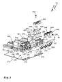
- Nachfolgend wird ein Ausführungsbeispiel der Erfindung anhand der Zeichnung erläutert. Es zeigen:
- Figur 1
- eine perspektivische Schrägansicht einer erfindungsgemäßen Hand-Werkzeugmaschine,
- Figur 2
- eine Anschlageinrichtung der Hand-Werkzeugmaschine gemäß
Figur 1 frontal von vorn, - Figur 3
- eine perspektivische Explosionsdarstellung der Anschlageinrichtung gemäß
Figur 2 , - Figur 4
- die Anschlageinrichtung gemäß
Figuren 2 ,3 mit teilweise ausgeschwenkten, teilweise zurück verstellten Verstellanschlägen, - Figur 5a
- eine teilweise Schnittdarstellung der Anschlageinrichtung gemäß
Figur 2 entlang einer Schnittlinie A-A inFigur 2 , wobei ein Verstellanschlag eine Anschlagstellung einnimmt, und - Figur 5b
- die Ansicht gemäß
Figur 5a , jedoch mit in Ruhestellung verstelltem Verstellanschlag. - Eine Hand-Werkzeugmaschine 10 weist einen Antriebsmotor 11 auf, der direkt oder über ein Getriebe 12 ein Zerspanungswerkzeug 13 antreibt. Bei dem Zerspanungswerkzeug 13 handelt es sich vorliegend um einen Fräser. Alternativ sind aber auch beispielsweise Bohrer, Frässcheiben oder Sägeblätter ohne weiteres möglich. Der Antriebsmotor 11 ist in einem Antriebsgehäuse 14 eines Antriebsteils 15 angeordnet. Die Hand-Werkzeugmaschine 10 ist eine elektrische Hand-Werkzeugmaschine, die beispielsweise über ein nicht dargestelltes elektrisches Versorgungskabel oder durch ein an Bord der Hand-Werkzeugmaschine 10 befindliches Energiespeicherbauteil, beispielsweise einen Akkupack, mit elektrischer Energie versorgt wird.
- Das Antriebsgehäuse 14 weist einen Handgriff 16 auf, der von einem Bediener umgriffen werden kann. Vom Handgriff 16 aus ist beispielsweise mit dem Daumen ein Antriebsschalter 17 betätigbar, mit dem der Antriebsmotor 11 einschaltbar ist. Der Antriebsmotor 11 ist in einem unteren Gehäusebereich 18 des Antriebsgehäuses 14, beispielsweise unterhalb des Handgriffs 16, angeordnet. Das Getriebe 12 befindet sich in einem dem Handgriff 16 vorgelagerten oberen Gehäusebereich 19 des Antriebsgehäuses 14. Das Zerspanungswerkzeug 13 steht unten frontal vor den Gehäusebereich 13 vor. Das Zerspanungswerkzeug 13 wird vom Antriebsmotor 11 oder motorisch angetrieben. Zudem umfasst das Getriebe 12 ein Pendelgetriebe derart, dass das Zerspanungswerkzeug 13 eine oszillierende Hin- und Herbewegung P durchläuft, um in ein schematisch dargestelltes Werkstück W Ausnehmungen, zum Beispiel Langlöcher, zu fräsen. In eine solche Ausnehmung kann beispielsweise ein Dübel, ein Beschlagteil oder dergleichen eingesetzt werden.
- Ein zweckmäßigerweise am Getriebe 12 einstellbarer Schwenkbereich der Hin- und Herbewegung P definiert eine Querlänge der Werkstück-Ausnehmung, während ein Durchmesser des Zerspanungswerkzeugs 13 eine Querbreite der Ausnehmung bestimmt.
- Eine Anschlageinrichtung 20 dient zur Anlage der Hand-Werkzeugmaschine 10 an das Werkstück W. Die Anschlageinrichtung 20 weist eine Frontanschlagfläche 21 auf, die zur Anlage an eine Frontseite F des Werkstücks W vorgesehen ist. Die Anschlageinrichtung 20 hat noch weitere Anschlagflächen, beispielsweise zur Anlage an dem Werkstück W. Eine Bodenfläche 22 der Anschlageinrichtung 20 ist beispielsweise winkelig, insbesondere rechtwinkelig, zur Frontanschlagfläche 21. Die Anschlageinrichtung 20 kann mit der Bodenfläche 22 beispielsweise auf eine dem Werkstück W vorgelagerte Fläche aufgelegt werden.
- Eine Winkelanlageplatte 23 stellt eine Winkelanschlagfläche 24 bereit, die in der in
Figur 1 dargestellten Position der Winkelanlageplatte mit der Frontanschlagfläche 21 fluchtet. Die Winkelanschlagfläche 24 ist um eine Schwenkachse 29 schwenkbar bezüglich der Frontanschlagfläche 21. Eine jeweilige Winkelstellung der Winkelanlageplatte 23 relativ zur Frontanschlagfläche 21 ist mit einer Schwenkeinstelleinrichtung 25 festlegbar. Selbstverständlich ist es vorteilhaft, wenn die beim Ausführungsbeispiel die Winkelanlageplatte 23 auch noch höhenverstellbar ist, so dass ihr Abstand zur Bodenfläche 22 verstellbar ist. - Die Anschlageinrichtung 20 weist zum Ergreifen durch einen Bediener noch einen Handgriff 26 auf, der vorzugsweise nach oben vor die Anschlageinrichtung 20 ergonomisch günstig absteht. Weiterhin ist noch ein Staubabfuhr-Anschluss 27 an der Anschlageinrichtung 20 vorgesehen, über den bei der Bearbeitung des Werkstücks W anfallender Staub oder anfallende Späne abgesaugt werden können.
- Die Anschlageinrichtung 20 relativ zum Antriebsteil 15, vorliegend linear, entlang eines Tiefenverstellwegs T verstellbar. Hierfür ist eine Führungsanordnung 30 vorgesehen, die die Anschlageinrichtung 20 linear bezüglich des Antriebsteils 15 führt. Anders formuliert könnte man aber auch sagen, dass das Antriebsteil 15 relativ zu der Anschlageinrichtung 20 geführt ist, da nämlich das Antriebsteil 15 zur Bearbeitung des Werkstücks W zu diesem hin, d.h. zu der Anschlageinrichtung 20 hin, bewegt wird, damit das Zerspanungswerkzeug 13 in das Werkstück W eindringt. Zuvor wird nämlich die Anschlageinrichtung 20 relativ zum Werkstück W positioniert, beispielsweise mit der Frontanschlagfläche 21 an die Werkstück-Frontseite F angelegt. Wenn das Antriebsteil 15 zu der Anschlageinrichtung 20 hin verstellt ist, steht das Zerspanungswerkzeug 13 vor die Frontanschlagfläche 21 vor. Beispielsweise könnte das Zerspanungswerkzeug 13 zwar neben der Frontanschlagfläche 21 angeordnet sein bzw. neben derselben vor diese vorstehen. Beim Ausführungsbeispiel ist jedoch an der Frontanschlagfläche 21 eine Ausnehmung 28 vorgesehen, durch die das Zerspanungswerkzeug 13 bei der Bearbeitung des Werkstücks W vor die Frontanschlagfläche 21 vor stehen kann.
- Die Führungsanordnung 30 umfasst an der Anschlageinrichtung 20 festgelegte Führungselemente 31. Die Führungselemente 31 umfassen beispielsweise Stangen, Rohre oder Stäbe 32, 33. Die Führungselemente 31 stehen in Richtung des Antriebsteils 15 bzw. des Antriebsgehäuses 14 vor die Anschlageinrichtung 20 vor. Die Führungselemente 31 sind in Führungsaufnahmen 34, 35 des Antriebsteils 15 verschieblich aufgenommen.
- Selbstverständlich könnte bei einer erfindungsgemäßen Hand-Werkzeugmaschine auch ein Führungselement, z.B. eine Stange, vom Antriebsteil abstehen und in eine Führungsaufnahme am Anschlagteil eingreifen.
- Die Führungsaufnahmen 34, 35 bilden Linearführungen für die Führungselemente 31. Die Führungsaufnahmen 34, 35 sind beispielsweise seitlich am Antriebsgehäuse 14 angeordnet, so dass sich das Getriebe 12 und/oder der Antriebsmotor 11 zwischen den Führungsaufnahmen 34, 35 befindet. Die Führungsaufnahmen 34, 35 bzw. die Führungselemente 31 verlaufen zweckmäßigerweise parallel zur Bodenfläche 22, wobei schräge Verläufe auch denkbar sind.
- Das Antriebsteil 15 und die Anschlageinrichtung 20 sind durch eine Federanordnung in einem Sinne voneinander weg beaufschlagt. Eine Feder 36 beaufschlagt das Antriebsteil 15 z.B. so, dass das Zerspanungswerkzeug 13 hinter die Frontanschlagfläche 21 zurückverstellt wird. Vorzugsweise ist geschützt in einem Innenraum eines oder beider Führungselemente 31 eine Feder 36 angeordnet. Die Feder 36 stützt sich z.B. an einem inneren Anschlag, z.B. der inneren Stirnseite, des Stabes 33 und einem Gegenhalt des Antriebsteils 15 ab, z.B. an einem stabartigen Vorsprung 37, der in den Innenraum des Stabes 33 eintaucht.
- Es versteht sich, dass selbstverständlich auch andersartige Führungen, beispielsweise Schwenklagerungen, Linear-Führungselemente, die vom Antriebsteil in Richtung der Anschlageinrichtung abstehen, oder dergleichen, ohne weiteres denkbar sind, auch wenn das beim Ausführungsbeispiel nicht realisiert ist.
- Das in der Zeichnung vordere Führungselement 31, der Stab 33, und die Führungsaufnahme 35 wirkt mit einer Tiefenanschlaganordnung 40 zusammen.
- Die Tiefenanschlaganordnung 40 umfasst einen Tiefenanschlagkörper 41, der an einer Tiefenanschlag-Lagereinrichtung 42 entlang eines Einstellwegs 43 linear beweglich gelagert ist. Die Tiefenanschlag-Lagereinrichtung 42 ist vorzugsweise zumindest teilweise mit dem Antriebsgehäuse 14 oder einem Getriebegehäuse verbunden, beispielsweise einstückig mit demselben und/oder mittels Schrauben, einer Klebeverbindung oder dergleichen, am Antriebsgehäuse 14 oder dem Getriebegehäuse befestigt.
- Der Einstellweg 43 verläuft parallel bzw. in axialer Verlängerung zum Tiefenverstellweg T. Das Führungselement 31, das die Führungsaufnahme 35 durchdringt, steht in eine Ausnehmung 47 der Tiefenanschlag-Lagereinrichtung 42 vor, jedenfalls wenn das Antriebsteil 15 zu der Anschlageinrichtung 20 hin verstellt ist, und schlägt an dem Tiefenanschlagkörper 41 an. Somit bestimmt also eine Längsposition des Tiefenanschlagkörpers 41 relativ zur Tiefenanschlag-Lagereinrichtung 42 die Eindringtiefe des Zerspanungswerkzeugs 13 in das Werkstück W.
- Die Tiefenanschlaganordnung 40 weist Indexkörper 44 auf, die ebenfalls an der Tiefenanschlag-Lagereinrichtung 42 beweglich gelagert sind, nämlich parallel zum Tiefenverstellweg T bzw. zum Einstellweg 43. Die Indexkörper 44 sind an einander entgegengesetzten Seiten des Tiefenanschlagkörpers 41 angeordnet und können dessen Verstellung entlang des Einstellwegs 43 begrenzen. Der Tiefenanschlagkörper 41 kann zwischen den Indexkörpern 44 hin- und her bewegt werden.
- Der Tiefenanschlagkörper 41 ist an einer Führungskulisse 45, die Indexkörper 44 sind an einer Führungskulisse 46 der Tiefenanschlag-Lagereinrichtung 42 geführt.
- Der Tiefenanschlagkörper 41 und die Indexkörper 44 sind jeweils individuell entlang der Führungskulisse in 45, 46 verstellbar und ortsfest festlegbar, beispielsweise verrastbar, verklemmbar oder dergleichen.
- Die Frontanschlagfläche 21 ist an einem Grundkörper 100 der Anschlageinrichtung 20 angeordnet. Der Grundkörper 100 hat eine Winkelgestalt und stellt zum einen die Bodenfläche 22, zum anderen die Frontanschlagfläche 21 bereit. An dem Grundkörper 100 ist die Winkelanlageplatte 23 schwenkbeweglich gelagert.
- Zur Einstellung variabler Querabstände der in das Werkstück W zu fräsenden Ausnehmung zu einer Seitenfläche des Werkstücks W, also zu einer Werkstück-Querseite Q, hat die Anschlageinrichtung 20 mehrere Verstellanschläge 110 an ihrer Frontseite, d.h. im Bereich der Frontanschlagfläche 21. Die Verstellanschläge 110 haben bezüglich einer Mittelachse 102 des Zerspanungswerkzeugs 13 bei dessen Pendelbewegung P oder - bezogen auf die Anschlageinrichtung 20 - bezüglich der Ausnehmung 28 verschiedene Querabstände.
- Bei den Verstellanschlägen 110 ist ein optimiertes Bedienkonzept realisiert, gemäß dem die Verstellanschläge 110 sehr einfach hinter die Frontanschlagfläche 21 in Anschlagaufnahmen 106 zurückverstellbar sind und dort einrasten. Die Verstellanschläge 110 können vollständig in die Anschlagaufnahmen 106 eintauchen, wo sie dann ihre Ruhestellung R einnehmen.
- Mittels einer Löseeinrichtung 130 können die Verstellanschläge 110 wieder aus der Verrastung gelöst werden, so dass sie vor die Frontanschlagfläche 21 selbsttätig vor schwenken. Hierfür ist eine Federbelastung vorgesehen, die in
Figur 1 nicht sichtbar ist. - Das Bedienkonzept sieht vor, dass jeder Verstellanschlag 110 individuell in seine Anschlagaufnahme 106 hinein verstellt, vorliegend geschwenkt, werden kann und dort verrastet.
- Eine Gruppe von mehreren, vorliegend 3, Verstellanschlägen 110 kann durch eine Betätigung einer ihnen zugeordneten Löseeinrichtung 130, beispielsweise durch Drücken eines Betätigungsvorsprungs 131 der Löseeinrichtung 130, aus dieser Verrastung gelöst werden, so dass die Verstellanschläge 110 wieder vor die Frontanschlagfläche 21 vor schwenken. Selbstverständlich wäre alternativ auch eine Schiebebewegung von Verstellanschlägen ohne weiteres möglich.
- Die Schwenklager 120 und/oder die Seitenwände der Anschlagaufnahmen 106 nehmen vorteilhaft Kräfte auf, die auf die Verstellanschläge 110 parallel zur Schwenkachse der Schwenklager 120 wirken.
- Es sind jeweils an beiden Seiten der Ausnehmung 28 drei Verstellanschläge 110 in Querabständen 103, 104, 105 angeordnet, so dass symmetrisch zur Mittelachse 102 jeweils entsprechende Querabstände der in das Werkstück W zu fräsenden Ausnehmung zu den Werkstück-Querseiten Q einstellbar sind. Selbstverständlich wäre auch eine asymmetrische Anordnung ohne weiteres möglich.
- Die Verstellanschläge 110 sind mit Schwenklagern 120 schwenkbar am Grundkörper 100 gelagert.
- An einem Lagerende 111 eines Verstellanschlags 110 ist eine Lageraufnahme 112 vorgesehen, die von einem Lagerachsteil 121 durchdrungen ist. Jeweils 3 an einer Seite der Ausnehmung 28 angeordnete Verstellanschläge 110 sind an einem einzigen Lagerachsteil 121 schwenkbar gelagert, wobei selbstverständlich eine individuelle Lagerung für jeden Verstellanschlag 110 auch möglich ist, z.B. mit direkt an Verstellanschlägen angeordneten Lageraufnahmen oder Lagervorsprüngen, einem individuellen Lagerachsteil pro Verstellanschlag oder dergleichen.
- Jeder Verstellanschlag 110 ist individuell vor die Frontanschlagfläche 21 vor und zurück schwenkbar.
- Das Lagerachsteil 121 ist in einer Achsaufnahme 122 des Grundkörpers 100 aufgenommen. Die Achsaufnahme 122 und das Lagerachsteil 121 erstrecken sich parallel zur Frontanschlagfläche 21. Mithin schwenken also die Verstellanschläge 110 um eine zur Frontanschlagfläche 21 parallele Schwenkachse.
- Die Achsaufnahmen 122 erstrecken sich bis zu Querseiten 101 des Grundkörpers 100. Die Querseiten 101 verlaufen quer, vorliegend rechtwinkelig, zur Frontanschlagfläche 21.
- Ein jeweiliges Lagerachsteil 121 ist von einer der Querseiten 101 her in die Achsaufnahme 122 eingesteckt. Die Achsaufnahme 122 ist an der jeweiligen Querseite 101 vorzugsweise durch einen Stopfen 123 verschlossen.
- Die Verstellanschläge 110 haben eine klinkenartige Gestalt.
- In
Figur 4 sind die inneren, am nächsten bei der Ausnehmung 28 angeordneten Verstellanschläge 110 in die Ruhestellung R verstellt, während die Verstellanschläge 110 nahe bei den Querseiten 101 in ihre Anschlagstellungen A vorgeschwenkt sind, bei der Anschlagabschnitte 113 der Verstellanschläge 110 vor die Frontanschlagfläche 21 vorstehen. Die Lagerenden 111 der Verstellanschläge 110 sind auch in der Anschlagstellung innerhalb der Anschlagaufnahmen 106. - Die Anschlagaufnahmen 106 sind grundsätzlich in der Art von Schlitzen ausgestaltet, haben jedoch in ihrem den Anschlagabschnitten 113 der Verstellanschläge 110 zugeordneten oberen Bereich zusätzliche Vertiefungen 107, die ein ergonomisches Bedienkonzept ermöglichen. Die Vertiefungen 107 sind muldenartig. Die Vertiefungen 107 haben eine Innenkontur, die etwa einer Fingerspitze angepasst ist. Von vorn, von der Frontanschlagfläche 21 her betrachtet, haben die Anschlagaufnahmen 106 die Gestalt eines Schlüsselloches.
- Ein Bediener kann also stirnseitig auf die Verstellanschläge 110 drücken, d.h. auf Stirnseiten 116 der Anschlagabschnitte 113, bis er in den Vertiefungen 107 mit seinem Finger anschlägt. Dann rasten die Verstellanschläge 110 ein, werden also selbsttätig in den Anschlagaufnahmen 106 zurückgehalten.
- Dabei ist es vorteilhaft, dass die Verstellanschläge 110 noch nicht in den Anschlagaufnahmen 106 verrasten, sondern frei beweglich bleiben, wenn sie lediglich so tief in die Anschlagaufnahmen 106 eingedrückt werden, dass ihre Stirnseiten 116 mit der Frontanschlagfläche 21 fluchten oder knapp hinter die Frontanschlagfläche 21 zurück verstellt sind. Somit kann ein beispielsweise an der Frontanschlagfläche 21 anliegendes Werkstück einen jeweiligen Verstellanschlag 110 nicht in der Anschlagaufnahme 106 verrasten. Vielmehr kommt der jeweilige Verstellanschlag 110 selbsttätig wieder aus der Anschlagaufnahme 106 heraus, wenn der Druck auf seine Stirnseite 116 nachlässt.
- Es ist vorteilhaft, dass die Stirnseiten 116 gerundet sind und/oder Schrägflächen aufweisen, so dass ein Gegenstand, zum Beispiel das Werkstück W, leicht auf die Stirnseiten 116 aufgleiten und den jeweiligen Anschlag beispielsweise in Richtung der Anschlagaufnahme 106 verstellen kann.
- Auch ein Außenumfang eines jeweiligen Anschlagabschnitts 113 ist vorzugsweise gerundet und/oder mit Schrägflächen versehen.
- An einem sich zwischen dem Lagerende 111 und den Anschlagabschnitt 113 erstreckenden Rücken 114 der Verstellanschläge 110 sind Rastausnehmungen 115 vorgesehen. In die Rastausnehmungen 115 rasten Rastvorsprünge 141 einer Rasteinrichtung 140 ein. Die Rastvorsprünge 141 sind in der Art von Armen oder Zungen ausgestaltet, die von einem gemeinsamen Träger 142 abstehen. Der Träger 142 bildet zugleich einen Bestandteil der Löseeinrichtung 130, was später noch deutlich wird.
- Die Rastvorsprünge 141 sind federnd nachgiebig am Träger 142 angeordnet und/oder in sich federnd nachgiebig. Somit geben die Rastvorsprünge 141 etwas nach, wenn der jeweilige Verstellanschlag 110 nach hinten, das heißt in die Anschlagaufnahme 106 hinein verstellt wird, und rasten dann in die Rastausnehmungen 115 ein.
- Die Rastvertiefungen oder Rastausnehmungen 115 sind im Querschnitt etwa V-förmig. An den Stirnseiten der Rastvorsprünge 141 sowie den diesen Stirnseiten zugewandten Flächen der Rastausnehmungen 115 sind vorzugsweise Schrägflächen angeordnet derart, dass die Rastvorsprünge 141 leicht in die Rastausnehmungen 115 hinein gleiten können.
- Durch ein axiales Verstellen der Löseeinrichtung 130 quer zur Einrastbewegung der Rastvorsprünge 141 in die Rastausnehmungen 115, vorliegend also beispielsweise parallel zur Schwenkachse der Schwenklager 120, können die Rastvorsprünge 141 zu den Rastausnehmungen 115 hin verstellt werden, d.h. die Rastvorsprünge 141 sind hinter oder in den Rastausnehmungen 115 positioniert. In dieser Stellung, einer Haltestellung H, ist es möglich, die Verstellanschläge 110 mit der Rasteinrichtung 140 zu verrasten oder die Verrastung aufrecht zu erhalten, wie beim vorderen Verstellanschlag 110 in
Figur 5b dargestellt. - Eine Federanordnung 150 beaufschlagt die Löseeinrichtung 130 in die Haltestellung H. Die Federanordnung 150 umfasst einen Federkörper 151. Eine Federzunge 152 des Federkörpers 151 belastet die Löseeinrichtung 130 in Richtung der Haltestellung H. Die Federzunge 152 wirkt beispielsweise auf den Betätigungsvorsprung 131. Die Federzunge 152 drückt beispielsweise den Betätigungsvorsprung 131 in Richtung der jeweiligen Querseite 101, d.h. nach quer außen.
- Es ist vorteilhaft eine weitere Federzunge 157 vorgesehen, die den Federkörper 151 insgesamt in Richtung der Haltestellung H der Löseeinrichtung 130 belastet.
- Der Federkörper 151 ist in einer Federaufnahme 160 des Grundkörpers 100 aufgenommen.
- Die Federzunge 157 stützt sich an einer Wand der Federaufnahme 160 ab.
- Die Federzunge 152 ist an einem Träger 153 des Federkörpers 151 angeordnet. Die Federzunge 152 befindet sich an einem Längsende des Trägers 153. Die Federzungen 152 und 157 sind vorteilhaft an entgegengesetzten Seiten des Federkörpers 151 angeordnet.
- Von dem Träger 153 stehen weiterhin Federzungen 154 ab, die die Verstellanschläge 110 in Richtung der Anschlagstellung A federnd beaufschlagen. Die Federzungen 154 umfassen jeweils einen Tragarm 155, der vom Träger 153 absteht. Vom Tragarm 155 steht ein Federarm 156 winkelig ab, beispielsweise U-förmig oder V-förmig.
- Der Federkörper 151 ist beispielsweise als ein Stanz-Biegeteil ausgestaltet. Der Federkörper 151 besteht beispielsweise aus Metall.
- Die Federaufnahme 160 befindet sich hinter den Anschlagaufnahmen 106. Die Federaufnahme 160 ist in der Art einer geschlossenen Kammer ausgestaltet, jedenfalls einer weitgehend geschlossenen Kammer. Jedenfalls ist die Federaufnahme 160 von oben her durch einen Deckel 161 verschlossen. Wenn also der Federkörper 151 in die Federaufnahme 160 eingesetzt ist, wird der Deckel 161 von oben her aufgesetzt und mit einer Schraube 162 oder einem sonstigen Befestigungsmittel befestigt, zum Beispiel auch angeklebt, verrastet oder dergleichen.
- Der Träger 153 ist vorliegend plattenartig und stützt sich beispielsweise auf Stützen 163 ab, die an, in oder bei der Federaufnahme 160 angeordnet sind. Eine der Stützen 163 bildet beispielsweise einen Schraubdom, in die die Schraube 162 geschraubt ist. Die Schraube 162 durchdringt vorteilhaft den Federkörper 151, zum Beispiel im Bereich des Trägers 153.
- Weiterhin weist die Federaufnahme 160 eine Rückwand oder Stützwand 164 auf, an der sich die Federzungen 154, beispielsweise deren Tragarme 155, abstützen können.
- Die Federzungen 154 wirken von hinten her auf die Verstellanschläge 110. Beispielsweise liegen die Federarme 156 im Wesentlichen flächig an den Rücken 114 der Verstellanschläge 110 an.
- Die von den Rastvorsprüngen 141 aufzubringenden Haltekräfte zum Halten eines jeweiligen Verstellanschlags 110 müssen lediglich ausreichen, um gegen die Kraft der Federanordnung 150 anzukommen.
- Die Anschlagaufnahmen 106 sind vorzugsweise rückseitig und/oder unten geöffnet. Jedenfalls sieht ein vorteilhaftes Konzept vor, dass Anschlagaufnahmen für Verstellanschläge nicht nur frontseitig offen sind, so dass die jeweiligen Verstellanschläge in die Anschlagaufnahmen hinein bewegbar sind, sondern eine zusätzliche Staubabfuhr- oder Spanabfuhröffnung aufweisen. Beim Ausführungsbeispiel sind die Anschlagaufnahmen 106 hinten offen, das heißt sie gehen unmittelbar in die Federaufnahme 160 über, die ihrerseits wieder unten, zur Bodenfläche 22 hin offen ist.
- An der Bodenfläche 22 ist beispielsweise eine Gleitplatte 170 angeordnet, zum Beispiel aus Edelstahl, einem gleitfähigen Kunststoff oder dergleichen. Die Gleitplatte 170 hat Durchtrittsöffnungen 171, durch die Späne, Staub oder sonstiger Schmutz aus den Anschlagaufnahmen 106 sowie auch der Federaufnahmen 160 nach unten herausfallen kann. Vorzugsweise sind die Durchtrittsöffnungen 171 im Bereich der Schwenklager 120 angeordnet, so dass gerade dort, wo eine leichte Beweglichkeit der Verstellanschläge 110 gewünscht ist, Späne oder sonstiger Schmutz abgeführt werden kann. Die Bodenplatte oder Gleitplatte 170 ist beispielsweise an den Grundkörper 100 angeschraubt, wofür passende Schraub- oder Durchtrittsöffnungen 172 vorgesehen sind.
- Selbstverständlich ist es auch möglich, dass beispielsweise in der Art von Schiebekörpern, beispielsweise Bolzen oder dergleichen, ausgestaltete Schiebe-Verstellanschläge bei einer erfindungsgemäß mit einer Rasteinrichtung versehenen Anschlageinrichtung vorhanden sind. In
Figur 3 ist schematisch ein solcher Schiebeanschlag 180 eingezeichnet, der linear, angedeutet durch einen Pfeil 181, zwischen einer vor die Frontanschlagfläche 21 vorstehenden Anschlagstellung und einer hinter diese zurück verstellte oder mit dieser fluchtenden Ruhestellung verstellbar ist. - Auf den Schiebeanschlag 180 wird zweckmäßigerweise ein Rastvorsprung 182, so dass der Schiebeanschlag 180 in der Ruhestellung und/oder auch in der Anschlagstellung, verrastbar ist. Der Rastvorsprung 182 wirkt auf eine Herzkurve 183 am Schiebeanschlag 180, so dass dieser in der Art einer Kugelschreibermine durch lineares Bewegen entlang seiner Schiebeachse zwischen der Anschlagstellung und der Ruhestellung verstellbar ist und zumindest in der Ruhestellung durch den Rastvorsprung 182 gehalten wird. Selbstverständlich sind auch andere Arten einer bistabilen Rasthaltung (alternativ zu einer Herzkurve) ohne weiteres möglich.
Claims (15)
- Hand-Werkzeugmaschine, insbesondere Dübelfräse, mit mindestens einem Zerspanungswerkzeug (13) zum Bohren und/oder Fräsen einer Ausnehmung in eine Werkstück-Frontseite (F) eines Werkstücks (W), mit einer Anschlageinrichtung (20) zur Anlage an das Werkstück (W), die eine Frontanschlagfläche (21) aufweist, und mit mindestens einem in einem Querabstand zu dem Werkzeug angeordneten Verstellanschlag (110), der zwischen einer Anschlagstellung (A), bei der der Verstellanschlag (110) vor die Frontanschlagfläche (21) vorsteht, und einer Ruhestellung (R) beweglich gelagert ist, in der der mindestens eine Verstellanschlag (110) nicht vor die Frontanschlagfläche (21) vorsteht oder hinter die Frontanschlagfläche (21) zurück verstellt ist, dadurch gekennzeichnet, dass sie eine Rasteinrichtung (140) zum Verrasten des mindestens einen Verstellanschlags (110) in mindestens einer Position des mindestens einen Verstellanschlags (110) relativ zu der Frontanschlagfläche (21) aufweist.
- Hand-Werkzeugmaschine nach Anspruch 1, dadurch gekennzeichnet, dass die Rasteinrichtung (140) zum Verrasten des mindestens einen Verstellanschlags (110) in der Ruhestellung (R) ausgestaltet ist.
- Hand-Werkzeugmaschine nach Anspruch 1 oder 2, dadurch gekennzeichnet, dass die Rasteinrichtung (140) bezüglich der Ruhestellung (R) nur in Rasteingriff mit dem mindestens einen Verstellanschlag (110) kommt, wenn eine vordere Stirnseite (116) des mindestens einen Verstellanschlags (110) hinter die Frontanschlagfläche (21) zurück verstellt ist, so dass der mindestens eine Verstellanschlag (110) bei einer Stellung, in der seine vordere Stirnseite (116) mit der Frontanschlagfläche (21) fluchtet, nicht verrastbar ist.
- Hand-Werkzeugmaschine nach einem der vorhergehenden Ansprüche, dadurch gekennzeichnet, dass sie mindestens zwei in einem ersten Abstand (103) und einem von dem ersten Abstand verschiedenen zweiten Abstand (104, 105) zu dem mindestens einen Zerspanungswerkzeug (13) oder einer Mittelachse (102) des Zerspanungswerkzeugs (13) angeordnete Verstellanschläge (110) und/oder an einander entgegengesetzten Seiten des mindestens einen Zerspanungswerkzeugs (13) angeordnete Verstellanschläge (110) aufweist.
- Hand-Werkzeugmaschine nach einem der vorhergehenden Ansprüche, dadurch gekennzeichnet, dass mindestens zwei Verstellanschläge (110) in einer Reihenrichtung nebeneinander, insbesondere entlang einer Reihenachse, angeordnet sind.
- Hand-Werkzeugmaschine nach einem der vorhergehenden Ansprüche, dadurch gekennzeichnet, dass sie eine Löseeinrichtung (130) zum Lösen der Verrastung der Rasteinrichtung (140) aufweist und/oder dass die Rasteinrichtung (140) eine bistabile Verrastung, insbesondere eine Herzkurve, umfasst, so dass die Verrastung anhand einer Druckbetätigung des mindestens einen Verstellanschlags (110) über eine Raststellung hinaus lösbar ist.
- Hand-Werkzeugmaschine nach Anspruch 6, dadurch gekennzeichnet, dass die Löseeinrichtung (130) zum Lösen der Verrastung von mindestens zwei Verstellanschlägen (110) ausgestaltet ist, so dass durch eine einzige, insbesondere axiale, Betätigung der Löseeinrichtung (130) die mindestens zwei Verstellanschläge (110) gleichzeitig aus der Verrastung gelöst werden können.
- Hand-Werkzeugmaschine nach Anspruch 6 oder 7, dadurch gekennzeichnet, dass die Löseeinrichtung (130) einen Träger (142) umfasst, an dem mindestens ein Rastvorsprung (141), vorzugsweise zwei Rastvorsprünge, zum Verrasten mit dem mindestens einen Verstellanschlag (110) vorhanden ist, und dass der Träger (142) bezüglich der Anschlageinrichtung (20) der Hand-Werkzeugmaschine (10) zwischen einer Lösestellung und einer Haltestellung beweglich, insbesondere schiebebeweglich, gelagert ist, wobei der mindestens eine Rastvorsprung (141) relativ zu dem mindestens einen Verstellanschlag (110) in der Haltestellung so verstellt ist, dass der mindestens eine Verstellanschlag (110) in Rasteingriff mit dem mindestens einen Rastvorsprung (141) gelangen kann, und in der Lösestellung so von dem mindestens einen Verstellanschlag (110) weg verstellt ist, dass der mindestens eine Rastvorsprung (141) und der mindestens eine Verstellanschlag (110) nicht in Eingriff gelangen können oder außer Eingriff sind.
- Hand-Werkzeugmaschine nach einem der Ansprüche 6 bis 8, dadurch gekennzeichnet, dass die Löseeinrichtung (130) durch eine Halte-Federanordnung (150, 152) im Sinne eines Haltens der Verrastung der Rasteinrichtung (140) mit dem mindestens einen Verstellanschlag (110) belastet ist.
- Hand-Werkzeugmaschine nach einem der vorhergehenden Ansprüche, dadurch gekennzeichnet, dass der mindestens eine Verstellanschlag (110) durch eine Ausrück-Federanordnung (150, 154) in Richtung der Anschlagstellung (A) belastet ist.
- Hand-Werkzeugmaschine nach Anspruch 9 oder 10, dadurch gekennzeichnet, dass sie einen einstückigen Federkörper (151) aufweist, der einen Bestandteil der Ausrück-Federanordnung und einen Bestandteil der Halte-Federanordnung bereitstellt.
- Hand-Werkzeugmaschine nach einem der vorhergehenden Ansprüche, dadurch gekennzeichnet, dass der mindestens eine Verstellanschlag (110) bezüglich der Anschlageinrichtung (20) oder an der Anschlageinrichtung (20) linear beweglich und/oder schwenkbeweglich, insbesondere in der Art einer Klinke, gelagert ist.
- Hand-Werkzeugmaschine nach einem der vorhergehenden Ansprüche, dadurch gekennzeichnet, dass die Anschlageinrichtung (20) mit dem mindestens einen Verstellanschlag (110) relativ zu einem das mindestens eine Zerspanungswerkzeug (13) und einen Antriebsmotor (11) für das mindestens eine Zerspanungswerkzeug (13) aufweisenden Antriebsteil (15) oder Antriebsgehäuse (14) beweglich, insbesondere schiebebeweglich und/oder in der Art eines Schlittens sind, gelagert ist.
- Hand-Werkzeugmaschine nach einem der vorhergehenden Ansprüche, dadurch gekennzeichnet, dass der mindestens eine Verstellanschlag (110) einen Queranschlag zum seitlichen Anlegen an eine zur Werkstück-Frontseite (F) winkelige Werkstück-Querseite (Q) zur Festlegung eines Querabstandes zwischen der Werkstück-Querseite (Q) und der Werkstück-Ausnehmung oder dem Zerspanungswerkzeug (13) bildet.
- Hand-Werkzeugmaschine nach einem der vorhergehenden Ansprüche, dadurch gekennzeichnet, dass das mindestens eine Zerspanungswerkzeug (13) vor eine Frontanschlagfläche (21) der Anschlageinrichtung (20) der Hand-Werkzeugmaschine (10) vorstehend oder vor die Frontanschlagfläche (21) vor verstellbar ist.
Applications Claiming Priority (1)
| Application Number | Priority Date | Filing Date | Title |
|---|---|---|---|
| DE102011102063.6A DE102011102063B4 (de) | 2011-05-19 | 2011-05-19 | Hand-Werkzeugmaschine mit einem beweglichen Verstellanschlag und einer Rasteinrichtung |
Publications (2)
| Publication Number | Publication Date |
|---|---|
| EP2524779A1 true EP2524779A1 (de) | 2012-11-21 |
| EP2524779B1 EP2524779B1 (de) | 2015-01-14 |
Family
ID=46052524
Family Applications (1)
| Application Number | Title | Priority Date | Filing Date |
|---|---|---|---|
| EP12003012.7A Active EP2524779B1 (de) | 2011-05-19 | 2012-04-28 | Hand-Werkzeugmaschine mit einem beweglichen Verstellanschlag |
Country Status (2)
| Country | Link |
|---|---|
| EP (1) | EP2524779B1 (de) |
| DE (1) | DE102011102063B4 (de) |
Citations (6)
| Publication number | Priority date | Publication date | Assignee | Title |
|---|---|---|---|---|
| US5217331A (en) * | 1992-02-27 | 1993-06-08 | Ericksen Colin W | Hardware installation tool |
| US5257654A (en) * | 1992-05-22 | 1993-11-02 | Black & Decker Inc. | Biscuit joiner with retractable antiskid pins |
| DE19844516A1 (de) * | 1998-09-28 | 2000-03-30 | Bernd Zarneckow | Tragbare Vorrichtung zur Erstellung von Dübellöchern und/oder Ausfräsungen |
| WO2000035643A1 (de) * | 1998-12-15 | 2000-06-22 | Gebhard Graf | Tragbare vorrichtung |
| DE102005036213B3 (de) * | 2005-08-02 | 2006-10-05 | Festool Gmbh | Fräsmaschine |
| DE102008008890A1 (de) | 2008-02-13 | 2009-08-20 | Festool Gmbh | Hand-Werkzeugmaschine |
Family Cites Families (1)
| Publication number | Priority date | Publication date | Assignee | Title |
|---|---|---|---|---|
| US4913204A (en) * | 1989-09-28 | 1990-04-03 | Black & Decker Inc. | Power biscuit jointer cutter |
-
2011
- 2011-05-19 DE DE102011102063.6A patent/DE102011102063B4/de active Active
-
2012
- 2012-04-28 EP EP12003012.7A patent/EP2524779B1/de active Active
Patent Citations (6)
| Publication number | Priority date | Publication date | Assignee | Title |
|---|---|---|---|---|
| US5217331A (en) * | 1992-02-27 | 1993-06-08 | Ericksen Colin W | Hardware installation tool |
| US5257654A (en) * | 1992-05-22 | 1993-11-02 | Black & Decker Inc. | Biscuit joiner with retractable antiskid pins |
| DE19844516A1 (de) * | 1998-09-28 | 2000-03-30 | Bernd Zarneckow | Tragbare Vorrichtung zur Erstellung von Dübellöchern und/oder Ausfräsungen |
| WO2000035643A1 (de) * | 1998-12-15 | 2000-06-22 | Gebhard Graf | Tragbare vorrichtung |
| DE102005036213B3 (de) * | 2005-08-02 | 2006-10-05 | Festool Gmbh | Fräsmaschine |
| DE102008008890A1 (de) | 2008-02-13 | 2009-08-20 | Festool Gmbh | Hand-Werkzeugmaschine |
Also Published As
| Publication number | Publication date |
|---|---|
| EP2524779B1 (de) | 2015-01-14 |
| DE102011102063B4 (de) | 2021-07-08 |
| DE102011102063A1 (de) | 2012-11-22 |
Similar Documents
| Publication | Publication Date | Title |
|---|---|---|
| EP3843959B1 (de) | Messer mit einem messergriff und einer klinge | |
| EP4234160B1 (de) | Führungssystem mit hand-werkzeugmaschine und führungsschiene | |
| DE102007021334A1 (de) | Elektrohandwerkzeugmaschinenanordnung | |
| WO2014001131A1 (de) | Werkzeugmaschinentrennvorrichtung | |
| EP2396151A2 (de) | Vorrichtung zum schneiden von laminat-fussbodenplatten | |
| DE202018103332U1 (de) | Linealadapter | |
| DE102010026023A1 (de) | Hand-Werkzeugmaschine mit einem Energiespeicher | |
| DE102004013066A1 (de) | Spann- und Spreizvorrichtung | |
| EP3162249B1 (de) | Einstellmittel für eine rastanordnung zur einstellung eines an einem möbelkorpus aufgenommenen bewegbaren möbelteils | |
| EP1466690B1 (de) | Säbelsäge mit Justiervorrichtung für eine Führungsvorrichtung | |
| EP2281482A1 (de) | Ausstoßvorrichtung einer Ausziehführung und Ausziehführung | |
| EP2524779B1 (de) | Hand-Werkzeugmaschine mit einem beweglichen Verstellanschlag | |
| DE102011082276A1 (de) | Auflagevorrichtung | |
| DE10214758B4 (de) | Vorrichtung zum Schneiden von Bodenbelägen | |
| DE102016109375A1 (de) | Werkzeugmaschine, insbesondere Kappsäge | |
| EP2524764B1 (de) | Hand-Werkzeugmaschine mit einer Tiefenanschlageinrichtung | |
| EP3246121B1 (de) | Werkzeugmaschine mit einem anlagekörper | |
| EP0855239A1 (de) | Schnellspannvorrichtung an einer Werkstück-Bearbeitungsmaschine | |
| DE102014001577A1 (de) | Hand-Werkzeugmaschine und Führungsschiene | |
| EP2974839B1 (de) | Hand-trennmaschine mit zwei gehrungslagern | |
| DE102008016765B3 (de) | Stichsäge mit Führungsfinne | |
| EP2813333A1 (de) | Ablängwerkzeug | |
| EP2974838B1 (de) | Hand-trennmaschine mit einer fixierbaren gehrungslageranordnung | |
| DE102006006592A1 (de) | Mechanismus zum Verriegeln eines Abschaberwerkzeugs | |
| DE8312309U1 (de) | Papierhandhabungsgerät |
Legal Events
| Date | Code | Title | Description |
|---|---|---|---|
| PUAI | Public reference made under article 153(3) epc to a published international application that has entered the european phase |
Free format text: ORIGINAL CODE: 0009012 |
|
| AK | Designated contracting states |
Kind code of ref document: A1 Designated state(s): AL AT BE BG CH CY CZ DE DK EE ES FI FR GB GR HR HU IE IS IT LI LT LU LV MC MK MT NL NO PL PT RO RS SE SI SK SM TR |
|
| AX | Request for extension of the european patent |
Extension state: BA ME |
|
| RAP1 | Party data changed (applicant data changed or rights of an application transferred) |
Owner name: FESTOOL GROUP GMBH & CO. KG |
|
| 17P | Request for examination filed |
Effective date: 20130410 |
|
| GRAP | Despatch of communication of intention to grant a patent |
Free format text: ORIGINAL CODE: EPIDOSNIGR1 |
|
| RIC1 | Information provided on ipc code assigned before grant |
Ipc: B27F 5/02 20060101AFI20140718BHEP Ipc: B27C 3/06 20060101ALI20140718BHEP Ipc: B27C 3/08 20060101ALI20140718BHEP |
|
| INTG | Intention to grant announced |
Effective date: 20140827 |
|
| RAP1 | Party data changed (applicant data changed or rights of an application transferred) |
Owner name: FESTOOL GMBH |
|
| GRAS | Grant fee paid |
Free format text: ORIGINAL CODE: EPIDOSNIGR3 |
|
| GRAA | (expected) grant |
Free format text: ORIGINAL CODE: 0009210 |
|
| AK | Designated contracting states |
Kind code of ref document: B1 Designated state(s): AL AT BE BG CH CY CZ DE DK EE ES FI FR GB GR HR HU IE IS IT LI LT LU LV MC MK MT NL NO PL PT RO RS SE SI SK SM TR |
|
| REG | Reference to a national code |
Ref country code: GB Ref legal event code: FG4D Free format text: NOT ENGLISH |
|
| REG | Reference to a national code |
Ref country code: CH Ref legal event code: EP |
|
| REG | Reference to a national code |
Ref country code: IE Ref legal event code: FG4D Free format text: LANGUAGE OF EP DOCUMENT: GERMAN |
|
| REG | Reference to a national code |
Ref country code: AT Ref legal event code: REF Ref document number: 706763 Country of ref document: AT Kind code of ref document: T Effective date: 20150215 |
|
| REG | Reference to a national code |
Ref country code: DE Ref legal event code: R096 Ref document number: 502012002066 Country of ref document: DE Effective date: 20150305 |
|
| REG | Reference to a national code |
Ref country code: NL Ref legal event code: VDEP Effective date: 20150114 |
|
| REG | Reference to a national code |
Ref country code: LT Ref legal event code: MG4D |
|
| PG25 | Lapsed in a contracting state [announced via postgrant information from national office to epo] |
Ref country code: HR Free format text: LAPSE BECAUSE OF FAILURE TO SUBMIT A TRANSLATION OF THE DESCRIPTION OR TO PAY THE FEE WITHIN THE PRESCRIBED TIME-LIMIT Effective date: 20150114 Ref country code: SE Free format text: LAPSE BECAUSE OF FAILURE TO SUBMIT A TRANSLATION OF THE DESCRIPTION OR TO PAY THE FEE WITHIN THE PRESCRIBED TIME-LIMIT Effective date: 20150114 Ref country code: ES Free format text: LAPSE BECAUSE OF FAILURE TO SUBMIT A TRANSLATION OF THE DESCRIPTION OR TO PAY THE FEE WITHIN THE PRESCRIBED TIME-LIMIT Effective date: 20150114 Ref country code: NO Free format text: LAPSE BECAUSE OF FAILURE TO SUBMIT A TRANSLATION OF THE DESCRIPTION OR TO PAY THE FEE WITHIN THE PRESCRIBED TIME-LIMIT Effective date: 20150414 Ref country code: FI Free format text: LAPSE BECAUSE OF FAILURE TO SUBMIT A TRANSLATION OF THE DESCRIPTION OR TO PAY THE FEE WITHIN THE PRESCRIBED TIME-LIMIT Effective date: 20150114 Ref country code: BG Free format text: LAPSE BECAUSE OF FAILURE TO SUBMIT A TRANSLATION OF THE DESCRIPTION OR TO PAY THE FEE WITHIN THE PRESCRIBED TIME-LIMIT Effective date: 20150414 Ref country code: LT Free format text: LAPSE BECAUSE OF FAILURE TO SUBMIT A TRANSLATION OF THE DESCRIPTION OR TO PAY THE FEE WITHIN THE PRESCRIBED TIME-LIMIT Effective date: 20150114 |
|
| PG25 | Lapsed in a contracting state [announced via postgrant information from national office to epo] |
Ref country code: GR Free format text: LAPSE BECAUSE OF FAILURE TO SUBMIT A TRANSLATION OF THE DESCRIPTION OR TO PAY THE FEE WITHIN THE PRESCRIBED TIME-LIMIT Effective date: 20150415 Ref country code: PL Free format text: LAPSE BECAUSE OF FAILURE TO SUBMIT A TRANSLATION OF THE DESCRIPTION OR TO PAY THE FEE WITHIN THE PRESCRIBED TIME-LIMIT Effective date: 20150114 Ref country code: IS Free format text: LAPSE BECAUSE OF FAILURE TO SUBMIT A TRANSLATION OF THE DESCRIPTION OR TO PAY THE FEE WITHIN THE PRESCRIBED TIME-LIMIT Effective date: 20150514 Ref country code: RS Free format text: LAPSE BECAUSE OF FAILURE TO SUBMIT A TRANSLATION OF THE DESCRIPTION OR TO PAY THE FEE WITHIN THE PRESCRIBED TIME-LIMIT Effective date: 20150114 Ref country code: NL Free format text: LAPSE BECAUSE OF FAILURE TO SUBMIT A TRANSLATION OF THE DESCRIPTION OR TO PAY THE FEE WITHIN THE PRESCRIBED TIME-LIMIT Effective date: 20150114 Ref country code: LV Free format text: LAPSE BECAUSE OF FAILURE TO SUBMIT A TRANSLATION OF THE DESCRIPTION OR TO PAY THE FEE WITHIN THE PRESCRIBED TIME-LIMIT Effective date: 20150114 |
|
| REG | Reference to a national code |
Ref country code: DE Ref legal event code: R097 Ref document number: 502012002066 Country of ref document: DE |
|
| PG25 | Lapsed in a contracting state [announced via postgrant information from national office to epo] |
Ref country code: CZ Free format text: LAPSE BECAUSE OF FAILURE TO SUBMIT A TRANSLATION OF THE DESCRIPTION OR TO PAY THE FEE WITHIN THE PRESCRIBED TIME-LIMIT Effective date: 20150114 Ref country code: EE Free format text: LAPSE BECAUSE OF FAILURE TO SUBMIT A TRANSLATION OF THE DESCRIPTION OR TO PAY THE FEE WITHIN THE PRESCRIBED TIME-LIMIT Effective date: 20150114 Ref country code: DK Free format text: LAPSE BECAUSE OF FAILURE TO SUBMIT A TRANSLATION OF THE DESCRIPTION OR TO PAY THE FEE WITHIN THE PRESCRIBED TIME-LIMIT Effective date: 20150114 Ref country code: SK Free format text: LAPSE BECAUSE OF FAILURE TO SUBMIT A TRANSLATION OF THE DESCRIPTION OR TO PAY THE FEE WITHIN THE PRESCRIBED TIME-LIMIT Effective date: 20150114 Ref country code: RO Free format text: LAPSE BECAUSE OF FAILURE TO SUBMIT A TRANSLATION OF THE DESCRIPTION OR TO PAY THE FEE WITHIN THE PRESCRIBED TIME-LIMIT Effective date: 20150114 |
|
| PLBE | No opposition filed within time limit |
Free format text: ORIGINAL CODE: 0009261 |
|
| STAA | Information on the status of an ep patent application or granted ep patent |
Free format text: STATUS: NO OPPOSITION FILED WITHIN TIME LIMIT |
|
| PG25 | Lapsed in a contracting state [announced via postgrant information from national office to epo] |
Ref country code: MC Free format text: LAPSE BECAUSE OF FAILURE TO SUBMIT A TRANSLATION OF THE DESCRIPTION OR TO PAY THE FEE WITHIN THE PRESCRIBED TIME-LIMIT Effective date: 20150114 Ref country code: LU Free format text: LAPSE BECAUSE OF FAILURE TO SUBMIT A TRANSLATION OF THE DESCRIPTION OR TO PAY THE FEE WITHIN THE PRESCRIBED TIME-LIMIT Effective date: 20150428 |
|
| REG | Reference to a national code |
Ref country code: CH Ref legal event code: PL |
|
| 26N | No opposition filed |
Effective date: 20151015 |
|
| PG25 | Lapsed in a contracting state [announced via postgrant information from national office to epo] |
Ref country code: IT Free format text: LAPSE BECAUSE OF FAILURE TO SUBMIT A TRANSLATION OF THE DESCRIPTION OR TO PAY THE FEE WITHIN THE PRESCRIBED TIME-LIMIT Effective date: 20150114 |
|
| REG | Reference to a national code |
Ref country code: IE Ref legal event code: MM4A |
|
| PG25 | Lapsed in a contracting state [announced via postgrant information from national office to epo] |
Ref country code: CH Free format text: LAPSE BECAUSE OF NON-PAYMENT OF DUE FEES Effective date: 20150430 Ref country code: LI Free format text: LAPSE BECAUSE OF NON-PAYMENT OF DUE FEES Effective date: 20150430 |
|
| REG | Reference to a national code |
Ref country code: FR Ref legal event code: PLFP Year of fee payment: 5 |
|
| PG25 | Lapsed in a contracting state [announced via postgrant information from national office to epo] |
Ref country code: SI Free format text: LAPSE BECAUSE OF FAILURE TO SUBMIT A TRANSLATION OF THE DESCRIPTION OR TO PAY THE FEE WITHIN THE PRESCRIBED TIME-LIMIT Effective date: 20150114 |
|
| PG25 | Lapsed in a contracting state [announced via postgrant information from national office to epo] |
Ref country code: IE Free format text: LAPSE BECAUSE OF NON-PAYMENT OF DUE FEES Effective date: 20150428 |
|
| PG25 | Lapsed in a contracting state [announced via postgrant information from national office to epo] |
Ref country code: MT Free format text: LAPSE BECAUSE OF FAILURE TO SUBMIT A TRANSLATION OF THE DESCRIPTION OR TO PAY THE FEE WITHIN THE PRESCRIBED TIME-LIMIT Effective date: 20150114 |
|
| REG | Reference to a national code |
Ref country code: FR Ref legal event code: PLFP Year of fee payment: 6 |
|
| PG25 | Lapsed in a contracting state [announced via postgrant information from national office to epo] |
Ref country code: HU Free format text: LAPSE BECAUSE OF FAILURE TO SUBMIT A TRANSLATION OF THE DESCRIPTION OR TO PAY THE FEE WITHIN THE PRESCRIBED TIME-LIMIT; INVALID AB INITIO Effective date: 20120428 Ref country code: SM Free format text: LAPSE BECAUSE OF FAILURE TO SUBMIT A TRANSLATION OF THE DESCRIPTION OR TO PAY THE FEE WITHIN THE PRESCRIBED TIME-LIMIT Effective date: 20150114 |
|
| PG25 | Lapsed in a contracting state [announced via postgrant information from national office to epo] |
Ref country code: CY Free format text: LAPSE BECAUSE OF FAILURE TO SUBMIT A TRANSLATION OF THE DESCRIPTION OR TO PAY THE FEE WITHIN THE PRESCRIBED TIME-LIMIT Effective date: 20150114 |
|
| PG25 | Lapsed in a contracting state [announced via postgrant information from national office to epo] |
Ref country code: PT Free format text: LAPSE BECAUSE OF FAILURE TO SUBMIT A TRANSLATION OF THE DESCRIPTION OR TO PAY THE FEE WITHIN THE PRESCRIBED TIME-LIMIT Effective date: 20150514 Ref country code: BE Free format text: LAPSE BECAUSE OF NON-PAYMENT OF DUE FEES Effective date: 20150430 |
|
| PG25 | Lapsed in a contracting state [announced via postgrant information from national office to epo] |
Ref country code: TR Free format text: LAPSE BECAUSE OF FAILURE TO SUBMIT A TRANSLATION OF THE DESCRIPTION OR TO PAY THE FEE WITHIN THE PRESCRIBED TIME-LIMIT Effective date: 20150114 |
|
| REG | Reference to a national code |
Ref country code: FR Ref legal event code: PLFP Year of fee payment: 7 |
|
| REG | Reference to a national code |
Ref country code: AT Ref legal event code: MM01 Ref document number: 706763 Country of ref document: AT Kind code of ref document: T Effective date: 20170428 |
|
| PG25 | Lapsed in a contracting state [announced via postgrant information from national office to epo] |
Ref country code: MK Free format text: LAPSE BECAUSE OF FAILURE TO SUBMIT A TRANSLATION OF THE DESCRIPTION OR TO PAY THE FEE WITHIN THE PRESCRIBED TIME-LIMIT Effective date: 20150114 |
|
| PG25 | Lapsed in a contracting state [announced via postgrant information from national office to epo] |
Ref country code: AT Free format text: LAPSE BECAUSE OF NON-PAYMENT OF DUE FEES Effective date: 20170428 |
|
| PG25 | Lapsed in a contracting state [announced via postgrant information from national office to epo] |
Ref country code: AL Free format text: LAPSE BECAUSE OF FAILURE TO SUBMIT A TRANSLATION OF THE DESCRIPTION OR TO PAY THE FEE WITHIN THE PRESCRIBED TIME-LIMIT Effective date: 20150114 |
|
| P01 | Opt-out of the competence of the unified patent court (upc) registered |
Effective date: 20230517 |
|
| PGFP | Annual fee paid to national office [announced via postgrant information from national office to epo] |
Ref country code: DE Payment date: 20250318 Year of fee payment: 14 |
|
| PGFP | Annual fee paid to national office [announced via postgrant information from national office to epo] |
Ref country code: GB Payment date: 20260302 Year of fee payment: 15 |
|
| PGFP | Annual fee paid to national office [announced via postgrant information from national office to epo] |
Ref country code: FR Payment date: 20260302 Year of fee payment: 15 |