EP2281482A1 - Ausstoßvorrichtung einer Ausziehführung und Ausziehführung - Google Patents
Ausstoßvorrichtung einer Ausziehführung und Ausziehführung Download PDFInfo
- Publication number
- EP2281482A1 EP2281482A1 EP10171990A EP10171990A EP2281482A1 EP 2281482 A1 EP2281482 A1 EP 2281482A1 EP 10171990 A EP10171990 A EP 10171990A EP 10171990 A EP10171990 A EP 10171990A EP 2281482 A1 EP2281482 A1 EP 2281482A1
- Authority
- EP
- European Patent Office
- Prior art keywords
- driver
- guide
- contour
- contours
- activator
- Prior art date
- Legal status (The legal status is an assumption and is not a legal conclusion. Google has not performed a legal analysis and makes no representation as to the accuracy of the status listed.)
- Granted
Links
- 230000007246 mechanism Effects 0.000 claims abstract description 8
- 239000012190 activator Substances 0.000 claims description 33
- 238000006073 displacement reaction Methods 0.000 claims description 5
- 230000008878 coupling Effects 0.000 description 8
- 238000010168 coupling process Methods 0.000 description 8
- 238000005859 coupling reaction Methods 0.000 description 8
- 230000006378 damage Effects 0.000 description 5
- 230000000630 rising effect Effects 0.000 description 2
- 230000009471 action Effects 0.000 description 1
- 230000008859 change Effects 0.000 description 1
- 230000006835 compression Effects 0.000 description 1
- 238000007906 compression Methods 0.000 description 1
- 238000005553 drilling Methods 0.000 description 1
- 238000004146 energy storage Methods 0.000 description 1
- 238000003780 insertion Methods 0.000 description 1
- 230000037431 insertion Effects 0.000 description 1
- 238000009434 installation Methods 0.000 description 1
- 238000000034 method Methods 0.000 description 1
- 230000008569 process Effects 0.000 description 1
Images


Classifications
-
- A—HUMAN NECESSITIES
- A47—FURNITURE; DOMESTIC ARTICLES OR APPLIANCES; COFFEE MILLS; SPICE MILLS; SUCTION CLEANERS IN GENERAL
- A47B—TABLES; DESKS; OFFICE FURNITURE; CABINETS; DRAWERS; GENERAL DETAILS OF FURNITURE
- A47B88/00—Drawers for tables, cabinets or like furniture; Guides for drawers
- A47B88/40—Sliding drawers; Slides or guides therefor
- A47B88/453—Actuated drawers
- A47B88/46—Actuated drawers operated by mechanically-stored energy, e.g. by springs
- A47B88/463—Actuated drawers operated by mechanically-stored energy, e.g. by springs self-opening
Definitions
- the present invention relates to an ejection device of a pull-out guide, in particular for drawers according to the preamble of claim 1 and a pull-out guide.
- a driver which is displaceable along an integrally formed on a guide housing guide, coupled to a locking mechanism arranged in a force storage such that releases the driver by pressing the drawer in the direction of the furniture body of the locking mechanism and the biased energy storage pushes the drawer in the opening direction , If the drawer is subsequently pushed back into the furniture carcass, the energy store is pretensioned and the catch is locked in place via the latching mechanism in a closed position biasing the energy store.
- the object of the present invention is to provide an ejection device which is designed in such a way that an abusive use of the ejection device described above does not bring about destruction of the ejection device or parts thereof.
- At least one of the contours integrally formed on the driver for receiving the activator can be lowered in the direction of the guide housing.
- a driver designed in this way simultaneously fulfills a plurality of functions in the ejection device.
- the function of preventing destruction of the ejection device can be incorporated into the same component, which causes the coupling to the latching mechanism, holds the drawer in the closed position and transmits the ejection energy of the energy accumulator.
- the costly installation of separate components to meet these requirements is therefore not necessary.
- At least one of the contours of the driver is formed with at least one ramp-like sliding surface, which rises in a direction of displacement of the driver away from an edge of the contour.
- At least one of the contours of the driver is provided with a recess on an underside facing the guide housing, so that the driver rests only partially on the guide housing in the region of the contour.
- one of the contours of the driver is formed with two ramp-like sliding surfaces, wherein the sliding surface leading away from the edge of the driver has a smaller pitch than the sliding surface rising from the opposite side of the contour.
- top, bottom, left, right, front, back, etc. refer exclusively to the exemplary representation and position of the pull-out guide and other parts selected in the respective figures. These terms are not intended to be limiting, that is to say, by different working positions or the mirror-symmetrical design or the like, these references may change.
- FIG. 1 is denoted by the reference numeral 1 a total of a variant of a pull-out according to the invention, which consists of a (not shown) furniture body guide rail 2, to which the ejection device 4 is fixed and a movable on the guide rail 2 running rail 3, to which an activator. 5 is fixed, with which the ejection device 4 can be activated during a closing or opening operation of a arranged on a furniture body movable furniture part.
- the pull-out guide 1 with the ejection device 4 arranged thereon serves in particular for the storage of drawers, but can also be used for other displaceable elements such as slide holders, shelves or the like.
- the ejector 4 has a displaceable by the activator 5 driver 8, which is displaceable in a guide housing 6 along at least one in the illustration shown here a plurality of guides 9, 17, 18.
- the guides 9 and 17 are preferably L-shaped designed to fix the driver 8 by insertion into the short leg of the L of the guides 9, 17 in an open position.
- the opening position refers to the moving out of a furniture body drawer.
- the ejection device 4 For fixing the driver 8 in a closed position (in which the drawer is fully inserted into the furniture body), the ejection device 4 preferably has a latching mechanism 11 with a control curve known from the prior art and a slidable along this control cam and coupled to the driver 8 Control 12 on (shown in FIG. 3 ) to the driver 8 against the force of a force accumulator 15 (also shown in FIG FIG. 3 ) in the closed position.
- the control element 12 preferably engages in a bore 88 in a base 89 of the driver 8.
- the energy accumulator 15 is coupled to the driver 8 via a coupling rod 14 which is coupled to a head piece on a coupling part 90 of the driver 8.
- the coupling rod 14 and the energy accumulator 15, which is preferably designed as a compression spring, are mounted in a housing 7, which is fastened via a coupling piece 13 to the guide housing 6.
- the driver 8 two spaced-apart, the receptacle 10, for receiving the activator 5, forming contours 81, 84.
- the first contour 81 is formed with two ramp-like sliding surfaces 82, 83 which rise away in a direction of displacement X of the driver 8 from the edges of the contour 81 extending transversely to the displacement direction X.
- the second contour 84 of the driver forms the second wall of the U- or V-shaped receptacle 10 for receiving the activator. 5
- the activator 5 is as in Figure 5a-e can be seen, preferably formed with two projecting into the receptacle 10 teeth 51, 52, whose width and distance from each other is such that the outer edges of the teeth 51, 52 in the working position of the activator 5, the receptacle 10 forming inner sides of the Touch outlines 81, 84.
- the driver 8 is provided on its underside with preferably three webs 85, 86, 87, which protrude into the guides 9, 17, 18 of the guide housing 6.
- the web 85 is designed to in that it surrounds the guide 9 from an underside of the guide housing 6 in order to prevent lifting of the driver 8 from the guide housing 6.
- the contour 81 of the driver 8 is provided on a guide housing 6 facing bottom with a recess 91 so that the driver 8 in the contour 81 rests only partially on the guide housing 6 and upon application of force to the contour 81st can yield in the direction of the guide housing 6 through the activator 5, whereby the height of the contour 81 is reduced and thereby the activator 5 can more easily slide over the contour 81 of the driver.
- the contour 81 or the connection of the contour 81 with the driver 8 is preferably elastic.
- the ramp-like sliding surfaces 82, 83 of the contour 81 are preferably designed such that the sliding surface 82 leading away from the edge of the driver 8 has a smaller pitch than the sliding surface 83 rising from the opposite side of the contour 81.
- the activator 5 is granted a sufficient hold in the direction of the contour 81 with only a moderate force of the activator 5, whereas, on the other hand, the activator 5 presses so strongly against the contour 81 that the contour 81 is pressed against the sliding surface 82 or deflecting towards the guide housing 6.
- the activator 5 can slide over the contour 81 and thus prevent destruction of the activator 5 or of the further parts of the ejection device 4 coupled to the driver 8.
- FIGS. 5a-e the sequence of such disengagement of the activator 5 is shown by the driver.
- the activator 5 is here with the driver 8 in engagement.
- the teeth 51, 52 of the activator 5 rest against the inner sides of the contours 81, 84.
- FIG. 5b shows a state in which the activator 5 is pressed against the contour 81.
- the contour 81 is bent over in the direction of the action of force and abuts the upper side 16 of the guide housing 6 with the underside of the contour 81, which is previously still separated from the guide housing 6 or the upper side of the guide housing 16.
- FIG. 5c the state where the first tooth 51 of the activator 5 has stepped out of the recess 10 of the driver 8 out. Depending on the condition of the guide housing 6, this can additionally give in slightly, so that the driver 8 is pressed in the contour 81 further down.
- FIGS. 5d to 5e is the sliding over of the second tooth 52 of the activator 5 shown on the contour 81, so that the activator in the in FIG. 5e shown position is completely solved by the driver 8.
Abstract
Description
- Die vorliegende Erfindung betrifft eine Ausstoßvorrichtung einer Ausziehführung, insbesondere für Schubkästen gemäß dem Oberbegriff des Anspruchs 1 sowie eine Ausziehführung.
- Gattungsgemäße Ausstoßvorrichtungen von Ausziehführungen für in einem Möbelkorpus eines Möbels ausziehbar gelagerten Schubkästen sind in zahlreichen Ausführungen aus dem Stand der Technik bekannt. Bei diesen wird ein Mitnehmer, der entlang einer an einem Führungsgehäuse angeformten Führung verschiebbar ist, mit einem in einem Rastmechanismus angeordneten Kraftspeicher derart gekoppelt, dass durch Drücken des Schubkastens in Richtung des Möbelkorpus der Rastmechanismus den Mitnehmer freigibt und der vorgespannte Kraftspeicher den Schubkasten in Öffnungsrichtung drückt. Wird der Schubkasten anschließend wieder in den Möbelkorpus hinein geschoben, wird der Kraftspeicher vorgespannt und der Mitnehmer über den Rastmechanismus in einer den Kraftspeicher vorspannenden Schließstellung verrastet.
- Problematisch bei diesen Ausstoßvorrichtungen ist, dass es bei verrasteten Ausstoßvorrichtungen durch missbräuchliche Benutzung, insbesondere durch Ziehen an dem Schubkasten, zur Beschädigung von Bauteilen der Ausstoßvorrichtung bis hin zu deren Zerstörung und damit zum vollständigen Funktionsverlust der Ausstoßvorrichtung kommen kann.
- Aufgabe der vorliegende Erfindung ist es, eine Ausstoßvorrichtung bereit zu stellen, die derart ausgebildet ist, dass eine oben beschriebene missbräuchliche Benutzung der Ausstoßvorrichtung nicht eine Zerstörung der Ausstoßvorrichtung oder Teile derselben herbeiführt.
- Diese Aufgabe wird durch eine Ausstoßvorrichtung einer Ausziehführung mit den Merkmalen des Anspruchs 1 sowie durch eine Ausziehführung mit den Merkmalen des Anspruchs 6 gelöst.
- Erfindungsgemäß ist mindestens eine der an dem Mitnehmer zur Aufnahme des Aktivators angeformten Konturen in Richtung des Führungsgehäuses absenkbar ausgebildet. Dadurch kann bei der Aufschlagung einer bestimmten Zugkraft auf den Mitnehmer ein bestimmter Teil des Mitnehmers in Richtung des Führungsgehäuses abtauchen, so dass der in dem Mitnehmer gehaltene Aktivator außer Eingriff des Mitnehmers gelangen kann.
- Vorteilhaft ist außerdem, dass ein derart gestalteter Mitnehmer gleichzeitig mehrere Funktionen in der Ausstoßvorrichtung erfüllt. Somit kann die Funktion zum Schutz vor Zerstörung der Ausstoßvorrichtung in das gleiche Bauteil eingearbeitet werden, welches die Ankopplung an den Rastmechanismus bewirkt, den Schubkasten in der geschlossenen Stellung hält sowie die Ausstoßenergie des Kraftspeichers überträgt. Der kostenträchtige Einbau separater Bauteile zur Erfüllung dieser Anforderungen ist somit nicht notwendig.
- Vorteilhafte Ausgestaltungen der Erfindung sind in den Unteransprüchen gekennzeichnet.
- Gemäß einer Ausführungsvariante ist mindestens eine der Konturen des Mitnehmers mit zumindest einer rampenartigen Gleitfläche ausgebildet, die in einer Verschieberichtung des Mitnehmers von einem Rand der Kontur weg ansteigt. Dadurch ist das Überlaufen des Aktivators über eine Haltekante des Mitnehmers erleichtert.
- Gemäß einer weiteren Ausführungsvariante ist mindestens eine der Konturen des Mitnehmers auf einer dem Führungsgehäuse zugewandten Unterseite mit einer Ausnehmung versehen, so dass der Mitnehmer im Bereich der Kontur nur teilweise auf dem Führungsgehäuse aufliegt. Dadurch kann beim Überlaufen des Aktivators über die Haltekante der Kontur die Kontur zum Führungsgehäuse hin umgebogen und damit in Richtung des Führungsgehäuses abgesenkt werden.
- Gemäß einer weiteren Ausführungsvariante ist eine der Konturen des Mitnehmers mit zwei rampenartigen Gleitflächen ausgebildet, wobei die von dem Rand des Mitnehmers wegführende Gleitfläche eine geringere Steigung als die von der gegenüber liegenden Seite der Kontur her ansteigende Gleitfläche aufweist. Dadurch wird das Überlaufen des Aktivators über die Kante der Kontur hinreichend erleichtert und bietet gleichzeitig bei einem Ziehen am Schubkasten mit einer nur geringen Kraft dem Aktivator einen sicheren Halt in dem Mitnehmer.
- Nachfolgend werden Ausführungsbeispiele der Erfindung anhand der beiliegenden Zeichnungen näher erläutert. Es zeigen:
- Figur 1
- eine schematische perspektivische Darstellung einer Ausführungs- form einer Ausziehführung mit daran angeordneter Ausstoßvor- richtung,
- Figur 2
- eine schematische perspektivische Darstellung der Ausstoßvor- richtung aus
Figur 1 , - Figur 3
- eine schematische Explosionsdarstellung der Ausstoßvorrichtung aus
Figur 2 , - Figuren 4a-d
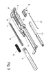
- verschiedene Ansichten einer Ausführungsvariante des Mitneh- mers der Ausstoßvorrichtung und
- Figuren 5a-e
- schematische Darstellungen des Bewegungsablaufes eines durch missbräuchlichen Zug eingeleiteten Außereingriffbringens des Ak- tivators aus dem Mitnehmer.
- In der nachfolgenden Figurenbeschreibung beziehen sich Begriffe wie oben, unten, links, rechts, vorne, hinten usw. ausschließlich auf die in den jeweiligen Figuren gewählte beispielhafte Darstellung und Position der Ausziehführung und anderer Teile. Diese Begriffe sind nicht einschränkend zu verstehen, das heißt, durch verschiedene Arbeitsstellungen oder die spiegelsymmetrische Auslegung oder dergleichen können sich diese Bezüge ändern.
- In
Figur 1 ist mit dem Bezugszeichen 1 insgesamt eine Ausführungsvariante einer erfindungsgemäßen Ausziehführung bezeichnet, die aus einer in einem (nicht gezeigten) Möbelkorpus festgelegten Führungsschiene 2 besteht, an der die Ausstoßvorrichtung 4 befestigt ist sowie einer auf der Führungsschiene 2 verfahrbaren Laufschiene 3, an der ein Aktivator 5 befestigt ist, mit dem die Ausstoßvorrichtung 4 während eines Schließ- oder Öffnungsvorgangs eines an einem Möbelkorpus angeordneten beweglichen Möbelteils aktivierbar ist. Die Ausziehführung 1 mit der daran angeordneten Ausstoßvorrichtung 4 dient insbesondere der Lagerung von Schubkästen, ist aber auch für andere verschiebbare Elemente wie Schiebehalter, Ablagen oder dergleichen einsetzbar. - Wie in
Figur 2 gezeigt, weist die Ausstoßvorrichtung 4 einen durch den Aktivator 5 verschiebbaren Mitnehmer 8 auf, der in einem Führungsgehäuse 6 entlang mindestens einer in der hier gezeigten Darstellung mehrerer Führungen 9, 17, 18 verschiebbar ist. Die Führungen 9 bzw. 17 sind dabei vorzugsweise L-förmig ausgebildet, um den Mitnehmer 8 durch Einschieben in den kurzen Schenkel des L der Führungen 9, 17 in einer Öffnungsposition zu fixieren. Die Öffnungsposition bezieht sich dabei auf den aus einem Möbelkorpus heraus bewegten Schubkasten. - Zur Fixierung des Mitnehmers 8 in einer Schließposition (bei der der Schubkasten vollständig in den Möbelkorpus eingeschoben ist), weist die Ausstoßvorrichtung 4 bevorzugt einen Rastmechanismus 11 mit einer aus dem Stand der Technik bekannten Steuerkurve sowie einem entlang dieser Steuerkurve verschiebbaren und mit dem Mitnehmer 8 gekoppelten Steuerelement 12 auf (gezeigt in
Figur 3 ), um den Mitnehmer 8 entgegen der Kraft eines Kraftspeichers 15 (ebenfalls gezeigt inFigur 3 ) in der Schließposition zu fixieren. Das Steuerelement 12 greift dabei bevorzugt in eine Bohrung 88 in einer Grundfläche 89 des Mitnehmers 8 ein. - Wie des Weiteren in
Figur 3 gezeigt ist, ist der Kraftspeicher 15 mit dem Mitnehmer 8 über eine Koppelstange 14 gekoppelt, die mit einem Kopfstück an einem Koppelteil 90 des Mitnehmers 8 angekoppelt ist. Die Koppelstange 14 und der Kraftspeicher 15, der bevorzugt als Druckfeder ausgebildet ist, sind in einem Gehäuse 7 gelagert, welches über ein Koppelstück 13 an dem Führungsgehäuse 6 befestigt ist. - Wie in den
Figuren 4a-d gezeigt ist, weist der Mitnehmer 8 zwei voneinander beabstandete, die Aufnahme 10, zur Aufnahme des Aktivators 5, bildende Konturen 81, 84 auf. Dabei ist die erste Kontur 81 mit zwei rampenartigen Gleitflächen 82, 83 ausgebildet, welche in einer Verschieberichtung X des Mitnehmers 8 von den quer zur Verschieberichtung X verlaufenden Rändern der Kontur 81 weg ansteigen. Die zweite Kontur 84 des Mitnehmers bildet die zweite Wand der U- bzw. V-förmigen Aufnahme 10 zur Aufnahme des Aktivators 5. - Der Aktivator 5 ist, wie in
Figur 5a-e zu erkennen ist, bevorzugt mit zwei in die Aufnahme 10 hineinragenden Zähnen 51, 52 ausgebildet, deren Breite und Abstand voneinander so bemessen ist, dass die außen liegenden Kanten der Zähne 51, 52 in der Arbeitsstellung des Aktivators 5 die die Aufnahme 10 bildenden Innenseiten der Konturen 81, 84 berühren. - Wie insbesondere in
Figur 4b zu erkennen ist, ist der Mitnehmer 8 auf seiner Unterseite mit bevorzugt drei Stegen 85, 86, 87 versehen, die in die Führungen 9, 17, 18 des Führungsgehäuses 6 hineinragen. Der Steg 85 ist so ausgebildet, dass er die Führung 9 von einer Unterseite des Führungsgehäuses 6 her umgreift, um ein Abheben des Mitnehmers 8 von dem Führungsgehäuse 6 zu verhindern. - Wie in den
Figuren 4a und d besonders gut zu erkennen ist, ist die Kontur 81 des Mitnehmers 8 auf einer dem Führungsgehäuse 6 zugewandten Unterseite mit einer Ausnehmung 91 versehen, so dass der Mitnehmer 8 im Bereich der Kontur 81 nur teilweise auf dem Führungsgehäuse 6 aufliegt und bei Krafteinwirkung auf die Kontur 81 durch den Aktivator 5 in Richtung des Führungsgehäuses 6 hin nachgeben kann, wodurch die Höhe der Kontur 81 vermindert wird und dadurch der Aktivator 5 leichter über die Kontur 81 des Mitnehmers hinweg gleiten kann. Um einen Bruch der Kontur 81 aufgrund der von dem Aktivator auf diese Kontur 81 ausgeübten Kraft zu verhindern, ist die Kontur 81 bzw. die Verbindung der Kontur 81 mit dem Mitnehmer 8 bevorzugt elastisch ausgebildet. - Die rampenartigen Gleitflächen 82, 83 der Kontur 81 sind dabei bevorzugt so ausgebildet, dass die vom Rand des Mitnehmers 8 wegführende Gleitfläche 82 eine geringere Steigung als die von der gegenüber liegende Seite der Kontur 81 her ansteigende Gleitfläche 83 aufweist. Dadurch wird dem Aktivator 5 bei einer nur mäßigen Krafteinwirkung des Aktivators 5 in Richtung der Kontur 81 ein hinreichender Halt gewährt, wo hingegen ab einer bestimmten Krafteinwirkung der Aktivator 5 so stark gegen die Kontur 81 drückt, dass die Kontur 81 sich zur Gleitfläche 82 bzw. zum Führungsgehäuse 6 hin abtauchend verbiegt. Dadurch kann der Aktivator 5 über die Kontur 81 hinweg gleiten und somit eine Zerstörung des Aktivators 5 bzw. der an dem Mitnehmer 8 angekoppelten weiteren Teile der Ausstoßvorrichtung 4 verhindern.
- In den
Figuren 5a-e ist der Ablauf eines solchen Außereingriffbringens des Aktivators 5 von dem Mitnehmer dargestellt. Wie inFigur 5a zu erkennen ist, ist der Aktivator 5 hier mit dem Mitnehmer 8 im Eingriff. Die Zähne 51, 52 des Aktivators 5 liegen dabei an den Innenseiten der Konturen 81, 84 an.Figur 5b zeigt einen Zustand, bei dem der Aktivator 5 gegen die Kontur 81 gedrückt wird. Dabei wird die Kontur 81 in Richtung der Krafteinwirkung hin umgebogen und stößt dabei mit der vorher noch von dem Führungsgehäuse 6 bzw. der Oberseite des Führungsgehäuses 16 beabstandeten Unterseite der Kontur 81 an die Oberseite 16 des Führungsgehäuses 6 an. Dadurch liegt der Zahn 51 des Aktivators 5 an der Gleitfläche 83 der Kontur 81 an, so dass ein Hinweggleiten über die Kontur 81 erleichtert ist. InFigur 5c ist der Zustand erreicht, wo der erste Zahn 51 des Aktivators 5 aus der Ausnehmung 10 des Mitnehmers 8 heraus getreten ist. Je nach Beschaffenheit des Führungsgehäuses 6 kann dieses dabei zusätzlich leicht nachgeben, so dass der Mitnehmer 8 im Bereich der Kontur 81 weiter nach unten gedrückt wird. - In den
Figuren 5d bis 5e ist das Übergleiten des zweiten Zahns 52 des Aktivators 5 über die Kontur 81 gezeigt, so dass der Aktivator in der inFigur 5e gezeigten Position vollständig von dem Mitnehmer 8 gelöst ist. -
- Ausziehführung
- 1
- Führungsschiene
- 2
- Laufschiene
- 3
- Ausstoßvorrichtung
- 4
- Aktivator
- 5
- Führungsgehäuse
- 6
- Gehäuse
- 7
- Mitnehmer
- 8
- Führung
- 9
- Aufnahme
- 10
- Rastmechanismus
- 11
- Steuerelement
- 12
- Koppelstück
- 13
- Koppelstange
- 14
- Kraftspeicher
- 15
- Oberseite des Führungsgehäuses
- 16
- Führung
- 17
- Führung
- 18
- Zahn
- 51
- Zahn
- 52
- Kontur
- 81
- Gleitfläche
- 82
- Gleitfläche
- 83
- Kontur
- 84
- Steg
- 85
- Steg
- 86
- Steg
- 87
- Bohrung
- 88
- Grundfläche
- 89
- Koppelteil
- 90
- Ausnehmung
- 91
- Verschieberichtung
- X
Claims (6)
- Ausstoßvorrichtung (4) einer Ausziehführung (1), insbesondere für Schubkästen, aufweisend- einen durch einen Aktivator (5) verschiebbaren Mitnehmer (8), der in einem Führungsgehäuse (6) entlang mindestens einer Führung (9, 17, 18) verschiebbar und in einer Öffnungsposition und einer Schließposition fixierbar ist,- wobei der Mitnehmer (8) mit einem Rastmechanismus (11) gekoppelt ist, um den Mitnehmer (8) entgegen der Kraft eines Kraftspeichers (15) in der Schließposition zu fixieren und- an dem Mitnehmer (8) zwei voneinander beabstandete, eine Aufnahme (10) zur Aufnahme des Aktivators bildende, Konturen (81, 84) angeformt sind,
dadurch gekennzeichnet, dass- mindestens eine der Konturen (81, 84) des Mitnehmers (8) in Richtung des Führungsgehäuses (6) absenkbar ausgebildet ist. - Ausstoßvorrichtung (4) nach Anspruch 1, dadurch gekennzeichnet, dass mindestens eine der Konturen (81, 84) des Mitnehmers (8) mit zumindest einer rampenartigen Gleitfläche (82, 83) ausgebildet ist, die in einer Verschieberichtung (X) des Mitnehmers (8) von einem Rand der Kontur (81, 84) weg ansteigt.
- Ausstoßvorrichtung (4) nach Anspruch 2, dadurch gekennzeichnet, dass mindestens eine der Konturen (81, 84) des Mitnehmers (8) auf einer dem Führungsgehäuse (6) zugewandten Unterseite mit einer Ausnehmung (91) versehen ist, so dass der Mitnehmer (8) im Bereich der Kontur nur teilweise auf dem Führungsgehäuse (6) aufliegt.
- Ausstoßvorrichtung (4) nach Anspruch 3, dadurch gekennzeichnet, dass mindestens eine der Konturen (81, 84) des Mitnehmers (8) elastisch an dem Mitnehmer (8) angeformt ist.
- Ausstoßvorrichtung (4) nach einem der Ansprüche 2 bis 4, dadurch gekennzeichnet, dass eine der Konturen (81, 84) des Mitnehmers (8) mit zwei rampenartigen Gleitflächen (82, 83) ausgebildet ist, wobei die von dem Rand des Mitnehmers (8) wegführende Gleitfläche (82) eine geringere Steigung als die von der gegenüberliegenden Seite der Kontur (81) her ansteigende Gleitfläche (83) aufweist.
- Ausziehführung (1), aufweisend eine an einem Möbelkorpus festlegbare Führungsschiene (2), an der eine Laufschiene (3) direkt oder über eine Mittelschiene geführt, ist, wobei an der Laufschiene (3) ein Aktivator (5) angeordnet ist, der mit einer Aufnahme (10) eines Mitnehmers (8) einer an der Führungsschiene (2) montierten Ausstoßvorrichtung (4) in Wirkverbindung steht, dadurch gekennzeichnet, dass die Ausstoßvorrichtung (4) nach einem der vorhergehenden Ansprüche ausgebildet ist.
Applications Claiming Priority (1)
| Application Number | Priority Date | Filing Date | Title |
|---|---|---|---|
| DE202009005121U DE202009005121U1 (de) | 2009-08-07 | 2009-08-07 | Ausstoßvorrichtung einer Ausziehführung und Ausziehführung |
Publications (2)
| Publication Number | Publication Date |
|---|---|
| EP2281482A1 true EP2281482A1 (de) | 2011-02-09 |
| EP2281482B1 EP2281482B1 (de) | 2012-05-09 |
Family
ID=42752131
Family Applications (1)
| Application Number | Title | Priority Date | Filing Date |
|---|---|---|---|
| EP10171990A Active EP2281482B1 (de) | 2009-08-07 | 2010-08-05 | Ausstoßvorrichtung einer Ausziehführung und Ausziehführung |
Country Status (5)
| Country | Link |
|---|---|
| EP (1) | EP2281482B1 (de) |
| CN (1) | CN102085051B (de) |
| AT (1) | ATE556620T1 (de) |
| DE (1) | DE202009005121U1 (de) |
| ES (1) | ES2387646T3 (de) |
Cited By (2)
| Publication number | Priority date | Publication date | Assignee | Title |
|---|---|---|---|---|
| WO2014056759A1 (de) | 2012-10-12 | 2014-04-17 | Paul Hettich Gmbh & Co. Kg | AUSSTOßVORRICHTUNG |
| JP2017516574A (ja) * | 2014-06-06 | 2017-06-22 | ユリウス ブルム ゲー エム ベー ハー | 可動家具部用の駆動装置 |
Families Citing this family (3)
| Publication number | Priority date | Publication date | Assignee | Title |
|---|---|---|---|---|
| AT512616B1 (de) | 2012-02-15 | 2017-05-15 | Blum Gmbh Julius | Möbel mit einer federbelasteten Antriebsvorrichtung für ein bewegbares Möbelteil |
| DE102013100652A1 (de) * | 2013-01-23 | 2014-07-24 | Paul Hettich Gmbh & Co | Beschleunigungsvorrichtung für bewegbare Möbel- oder Haushaltsgeräteteile |
| DE102019117593A1 (de) * | 2019-06-28 | 2020-12-31 | Paul Hettich Gmbh & Co. Kg | Ausstoßvorrichtung für ein bewegbares Möbelteil |
Citations (2)
| Publication number | Priority date | Publication date | Assignee | Title |
|---|---|---|---|---|
| DE202005009860U1 (de) * | 2004-12-17 | 2006-04-20 | Alfit Ag | Schließ- und Öffnungsvorrichtung für Schubladen |
| EP2208441A1 (de) * | 2009-01-19 | 2010-07-21 | Paul Hettich GmbH & Co. KG | Rastmechanismus und Möbel |
Family Cites Families (1)
| Publication number | Priority date | Publication date | Assignee | Title |
|---|---|---|---|---|
| AT503066B1 (de) * | 2004-12-03 | 2008-01-15 | Blum Gmbh Julius | Antriebsvorrichtung für ein bewegbar gelagertes möbelteil |
-
2009
- 2009-08-07 DE DE202009005121U patent/DE202009005121U1/de not_active Expired - Lifetime
-
2010
- 2010-08-05 AT AT10171990T patent/ATE556620T1/de active
- 2010-08-05 ES ES10171990T patent/ES2387646T3/es active Active
- 2010-08-05 EP EP10171990A patent/EP2281482B1/de active Active
- 2010-08-06 CN CN201010621684.9A patent/CN102085051B/zh active Active
Patent Citations (2)
| Publication number | Priority date | Publication date | Assignee | Title |
|---|---|---|---|---|
| DE202005009860U1 (de) * | 2004-12-17 | 2006-04-20 | Alfit Ag | Schließ- und Öffnungsvorrichtung für Schubladen |
| EP2208441A1 (de) * | 2009-01-19 | 2010-07-21 | Paul Hettich GmbH & Co. KG | Rastmechanismus und Möbel |
Cited By (6)
| Publication number | Priority date | Publication date | Assignee | Title |
|---|---|---|---|---|
| WO2014056759A1 (de) | 2012-10-12 | 2014-04-17 | Paul Hettich Gmbh & Co. Kg | AUSSTOßVORRICHTUNG |
| DE102012109752A1 (de) | 2012-10-12 | 2014-04-17 | Paul Hettich Gmbh & Co. Kg | Ausstoßvorrichtung |
| CN104703512A (zh) * | 2012-10-12 | 2015-06-10 | 保罗海蒂诗有限及两合公司 | 弹射装置 |
| KR20150070193A (ko) * | 2012-10-12 | 2015-06-24 | 파울 헤티히 게엠베하 운트 콤파니 카게 | 인출 장치 |
| JP2017516574A (ja) * | 2014-06-06 | 2017-06-22 | ユリウス ブルム ゲー エム ベー ハー | 可動家具部用の駆動装置 |
| US10188208B2 (en) | 2014-06-06 | 2019-01-29 | Julius Blum Gmbh | Drive mechanism for a movable furniture part |
Also Published As
| Publication number | Publication date |
|---|---|
| DE202009005121U1 (de) | 2010-12-30 |
| ES2387646T3 (es) | 2012-09-27 |
| EP2281482B1 (de) | 2012-05-09 |
| CN102085051B (zh) | 2014-08-06 |
| ATE556620T1 (de) | 2012-05-15 |
| CN102085051A (zh) | 2011-06-08 |
Similar Documents
| Publication | Publication Date | Title |
|---|---|---|
| DE102011053840B4 (de) | Einzugsvorrichtung zum Einbau in eine Auszugsführung | |
| EP2242082B1 (de) | Halter für Sicherungen | |
| AT10097U1 (de) | Federpuffer für ein möbel | |
| WO2008077946A2 (de) | Kältegerät | |
| AT511329A4 (de) | Verriegelbare ausstossvorrichtung mit überlastmechanismus | |
| DE102016107918A1 (de) | Ausstoßvorrichtung für ein bewegbares Möbelteil und Möbel | |
| EP1865808A1 (de) | Teleskopführung für ein in einem möbelkorpus verschiebbar angeordnetes möbelteil | |
| EP2281482B1 (de) | Ausstoßvorrichtung einer Ausziehführung und Ausziehführung | |
| EP2498643B1 (de) | Vorrichtung zur koppelung eines schubkastens mit einer laufschiene einer auszugsführung | |
| AT511905A1 (de) | Schublade | |
| EP3181013A1 (de) | Auswerferanordnung für ein bewegbares möbelteil | |
| DE112011101781T5 (de) | Verstellbares Rast-Rückhaltesystem und Verfahren | |
| DE102015106856A1 (de) | Vorrichtung und Verfahren zum Festlegen eines Schubelementes | |
| DE202009002035U1 (de) | Auszugsführung | |
| EP2078812A2 (de) | Abdeckelement für eine Gleitschiene | |
| EP2140395A2 (de) | Sim-kartenleser mit fixierbarer schublade | |
| DE102010038247A1 (de) | Schließsystem eines ausziehbaren Möbelteils und Möbel | |
| DE102012109751B4 (de) | Auszugführung eines ausziehbaren Möbelteils und Möbel | |
| EP3189749A1 (de) | Ausziehführung für ein bewegbares möbelteil | |
| WO2019197133A1 (de) | Auszugsführung | |
| EP2292119B1 (de) | Rastbeschlag und Auszugsführung | |
| DE202010018353U1 (de) | Auszugsführung | |
| EP3025938A1 (de) | Abdeckvorrichtung für eine flächenseite eines wandelements | |
| DE102019107690A1 (de) | Einzugs- oder Ausstoßvorrichtung | |
| EP1470771A1 (de) | Auszugführung |
Legal Events
| Date | Code | Title | Description |
|---|---|---|---|
| PUAI | Public reference made under article 153(3) epc to a published international application that has entered the european phase |
Free format text: ORIGINAL CODE: 0009012 |
|
| AK | Designated contracting states |
Kind code of ref document: A1 Designated state(s): AL AT BE BG CH CY CZ DE DK EE ES FI FR GB GR HR HU IE IS IT LI LT LU LV MC MK MT NL NO PL PT RO SE SI SK SM TR |
|
| AX | Request for extension of the european patent |
Extension state: BA ME RS |
|
| 17P | Request for examination filed |
Effective date: 20110302 |
|
| GRAP | Despatch of communication of intention to grant a patent |
Free format text: ORIGINAL CODE: EPIDOSNIGR1 |
|
| RIC1 | Information provided on ipc code assigned before grant |
Ipc: A47B 88/04 20060101AFI20111111BHEP |
|
| GRAS | Grant fee paid |
Free format text: ORIGINAL CODE: EPIDOSNIGR3 |
|
| GRAA | (expected) grant |
Free format text: ORIGINAL CODE: 0009210 |
|
| AK | Designated contracting states |
Kind code of ref document: B1 Designated state(s): AL AT BE BG CH CY CZ DE DK EE ES FI FR GB GR HR HU IE IS IT LI LT LU LV MC MK MT NL NO PL PT RO SE SI SK SM TR |
|
| REG | Reference to a national code |
Ref country code: GB Ref legal event code: FG4D Free format text: NOT ENGLISH |
|
| REG | Reference to a national code |
Ref country code: AT Ref legal event code: REF Ref document number: 556620 Country of ref document: AT Kind code of ref document: T Effective date: 20120515 Ref country code: CH Ref legal event code: EP |
|
| REG | Reference to a national code |
Ref country code: IE Ref legal event code: FG4D Free format text: LANGUAGE OF EP DOCUMENT: GERMAN |
|
| REG | Reference to a national code |
Ref country code: DE Ref legal event code: R096 Ref document number: 502010000705 Country of ref document: DE Effective date: 20120712 |
|
| REG | Reference to a national code |
Ref country code: NL Ref legal event code: VDEP Effective date: 20120509 |
|
| REG | Reference to a national code |
Ref country code: ES Ref legal event code: FG2A Ref document number: 2387646 Country of ref document: ES Kind code of ref document: T3 Effective date: 20120927 |
|
| REG | Reference to a national code |
Ref country code: LT Ref legal event code: MG4D Effective date: 20120509 |
|
| PG25 | Lapsed in a contracting state [announced via postgrant information from national office to epo] |
Ref country code: IS Free format text: LAPSE BECAUSE OF FAILURE TO SUBMIT A TRANSLATION OF THE DESCRIPTION OR TO PAY THE FEE WITHIN THE PRESCRIBED TIME-LIMIT Effective date: 20120909 Ref country code: SE Free format text: LAPSE BECAUSE OF FAILURE TO SUBMIT A TRANSLATION OF THE DESCRIPTION OR TO PAY THE FEE WITHIN THE PRESCRIBED TIME-LIMIT Effective date: 20120509 Ref country code: CY Free format text: LAPSE BECAUSE OF FAILURE TO SUBMIT A TRANSLATION OF THE DESCRIPTION OR TO PAY THE FEE WITHIN THE PRESCRIBED TIME-LIMIT Effective date: 20120509 Ref country code: LT Free format text: LAPSE BECAUSE OF FAILURE TO SUBMIT A TRANSLATION OF THE DESCRIPTION OR TO PAY THE FEE WITHIN THE PRESCRIBED TIME-LIMIT Effective date: 20120509 Ref country code: PL Free format text: LAPSE BECAUSE OF FAILURE TO SUBMIT A TRANSLATION OF THE DESCRIPTION OR TO PAY THE FEE WITHIN THE PRESCRIBED TIME-LIMIT Effective date: 20120509 Ref country code: NO Free format text: LAPSE BECAUSE OF FAILURE TO SUBMIT A TRANSLATION OF THE DESCRIPTION OR TO PAY THE FEE WITHIN THE PRESCRIBED TIME-LIMIT Effective date: 20120809 Ref country code: FI Free format text: LAPSE BECAUSE OF FAILURE TO SUBMIT A TRANSLATION OF THE DESCRIPTION OR TO PAY THE FEE WITHIN THE PRESCRIBED TIME-LIMIT Effective date: 20120509 |
|
| PG25 | Lapsed in a contracting state [announced via postgrant information from national office to epo] |
Ref country code: GR Free format text: LAPSE BECAUSE OF FAILURE TO SUBMIT A TRANSLATION OF THE DESCRIPTION OR TO PAY THE FEE WITHIN THE PRESCRIBED TIME-LIMIT Effective date: 20120810 Ref country code: LV Free format text: LAPSE BECAUSE OF FAILURE TO SUBMIT A TRANSLATION OF THE DESCRIPTION OR TO PAY THE FEE WITHIN THE PRESCRIBED TIME-LIMIT Effective date: 20120509 Ref country code: HR Free format text: LAPSE BECAUSE OF FAILURE TO SUBMIT A TRANSLATION OF THE DESCRIPTION OR TO PAY THE FEE WITHIN THE PRESCRIBED TIME-LIMIT Effective date: 20120509 Ref country code: SI Free format text: LAPSE BECAUSE OF FAILURE TO SUBMIT A TRANSLATION OF THE DESCRIPTION OR TO PAY THE FEE WITHIN THE PRESCRIBED TIME-LIMIT Effective date: 20120509 Ref country code: PT Free format text: LAPSE BECAUSE OF FAILURE TO SUBMIT A TRANSLATION OF THE DESCRIPTION OR TO PAY THE FEE WITHIN THE PRESCRIBED TIME-LIMIT Effective date: 20120910 |
|
| PG25 | Lapsed in a contracting state [announced via postgrant information from national office to epo] |
Ref country code: EE Free format text: LAPSE BECAUSE OF FAILURE TO SUBMIT A TRANSLATION OF THE DESCRIPTION OR TO PAY THE FEE WITHIN THE PRESCRIBED TIME-LIMIT Effective date: 20120509 Ref country code: NL Free format text: LAPSE BECAUSE OF FAILURE TO SUBMIT A TRANSLATION OF THE DESCRIPTION OR TO PAY THE FEE WITHIN THE PRESCRIBED TIME-LIMIT Effective date: 20120509 Ref country code: RO Free format text: LAPSE BECAUSE OF FAILURE TO SUBMIT A TRANSLATION OF THE DESCRIPTION OR TO PAY THE FEE WITHIN THE PRESCRIBED TIME-LIMIT Effective date: 20120509 Ref country code: SK Free format text: LAPSE BECAUSE OF FAILURE TO SUBMIT A TRANSLATION OF THE DESCRIPTION OR TO PAY THE FEE WITHIN THE PRESCRIBED TIME-LIMIT Effective date: 20120509 Ref country code: DK Free format text: LAPSE BECAUSE OF FAILURE TO SUBMIT A TRANSLATION OF THE DESCRIPTION OR TO PAY THE FEE WITHIN THE PRESCRIBED TIME-LIMIT Effective date: 20120509 Ref country code: CZ Free format text: LAPSE BECAUSE OF FAILURE TO SUBMIT A TRANSLATION OF THE DESCRIPTION OR TO PAY THE FEE WITHIN THE PRESCRIBED TIME-LIMIT Effective date: 20120509 |
|
| BERE | Be: lapsed |
Owner name: PAUL HETTICH G.M.B.H. & CO. KG Effective date: 20120831 |
|
| PLBE | No opposition filed within time limit |
Free format text: ORIGINAL CODE: 0009261 |
|
| STAA | Information on the status of an ep patent application or granted ep patent |
Free format text: STATUS: NO OPPOSITION FILED WITHIN TIME LIMIT |
|
| PG25 | Lapsed in a contracting state [announced via postgrant information from national office to epo] |
Ref country code: MC Free format text: LAPSE BECAUSE OF NON-PAYMENT OF DUE FEES Effective date: 20120831 |
|
| 26N | No opposition filed |
Effective date: 20130212 |
|
| REG | Reference to a national code |
Ref country code: IE Ref legal event code: MM4A |
|
| PG25 | Lapsed in a contracting state [announced via postgrant information from national office to epo] |
Ref country code: BE Free format text: LAPSE BECAUSE OF NON-PAYMENT OF DUE FEES Effective date: 20120831 |
|
| REG | Reference to a national code |
Ref country code: DE Ref legal event code: R097 Ref document number: 502010000705 Country of ref document: DE Effective date: 20130212 |
|
| PG25 | Lapsed in a contracting state [announced via postgrant information from national office to epo] |
Ref country code: BG Free format text: LAPSE BECAUSE OF FAILURE TO SUBMIT A TRANSLATION OF THE DESCRIPTION OR TO PAY THE FEE WITHIN THE PRESCRIBED TIME-LIMIT Effective date: 20120809 Ref country code: IE Free format text: LAPSE BECAUSE OF NON-PAYMENT OF DUE FEES Effective date: 20120805 |
|
| PG25 | Lapsed in a contracting state [announced via postgrant information from national office to epo] |
Ref country code: MT Free format text: LAPSE BECAUSE OF FAILURE TO SUBMIT A TRANSLATION OF THE DESCRIPTION OR TO PAY THE FEE WITHIN THE PRESCRIBED TIME-LIMIT Effective date: 20120509 Ref country code: AL Free format text: LAPSE BECAUSE OF FAILURE TO SUBMIT A TRANSLATION OF THE DESCRIPTION OR TO PAY THE FEE WITHIN THE PRESCRIBED TIME-LIMIT Effective date: 20120509 |
|
| PG25 | Lapsed in a contracting state [announced via postgrant information from national office to epo] |
Ref country code: LU Free format text: LAPSE BECAUSE OF NON-PAYMENT OF DUE FEES Effective date: 20120805 Ref country code: SM Free format text: LAPSE BECAUSE OF FAILURE TO SUBMIT A TRANSLATION OF THE DESCRIPTION OR TO PAY THE FEE WITHIN THE PRESCRIBED TIME-LIMIT Effective date: 20120509 |
|
| PG25 | Lapsed in a contracting state [announced via postgrant information from national office to epo] |
Ref country code: HU Free format text: LAPSE BECAUSE OF FAILURE TO SUBMIT A TRANSLATION OF THE DESCRIPTION OR TO PAY THE FEE WITHIN THE PRESCRIBED TIME-LIMIT Effective date: 20100805 |
|
| REG | Reference to a national code |
Ref country code: CH Ref legal event code: PL |
|
| GBPC | Gb: european patent ceased through non-payment of renewal fee |
Effective date: 20140805 |
|
| PG25 | Lapsed in a contracting state [announced via postgrant information from national office to epo] |
Ref country code: CH Free format text: LAPSE BECAUSE OF NON-PAYMENT OF DUE FEES Effective date: 20140831 Ref country code: LI Free format text: LAPSE BECAUSE OF NON-PAYMENT OF DUE FEES Effective date: 20140831 |
|
| PG25 | Lapsed in a contracting state [announced via postgrant information from national office to epo] |
Ref country code: MK Free format text: LAPSE BECAUSE OF FAILURE TO SUBMIT A TRANSLATION OF THE DESCRIPTION OR TO PAY THE FEE WITHIN THE PRESCRIBED TIME-LIMIT Effective date: 20120509 Ref country code: GB Free format text: LAPSE BECAUSE OF NON-PAYMENT OF DUE FEES Effective date: 20140805 |
|
| REG | Reference to a national code |
Ref country code: FR Ref legal event code: PLFP Year of fee payment: 7 |
|
| REG | Reference to a national code |
Ref country code: DE Ref legal event code: R079 Ref document number: 502010000705 Country of ref document: DE Free format text: PREVIOUS MAIN CLASS: A47B0088040000 Ipc: A47B0088400000 |
|
| REG | Reference to a national code |
Ref country code: FR Ref legal event code: PLFP Year of fee payment: 8 |
|
| REG | Reference to a national code |
Ref country code: FR Ref legal event code: PLFP Year of fee payment: 9 |
|
| PGFP | Annual fee paid to national office [announced via postgrant information from national office to epo] |
Ref country code: FR Payment date: 20190822 Year of fee payment: 10 |
|
| PG25 | Lapsed in a contracting state [announced via postgrant information from national office to epo] |
Ref country code: FR Free format text: LAPSE BECAUSE OF NON-PAYMENT OF DUE FEES Effective date: 20200831 |
|
| P01 | Opt-out of the competence of the unified patent court (upc) registered |
Effective date: 20230419 |
|
| PGFP | Annual fee paid to national office [announced via postgrant information from national office to epo] |
Ref country code: TR Payment date: 20230731 Year of fee payment: 14 Ref country code: IT Payment date: 20230831 Year of fee payment: 14 Ref country code: ES Payment date: 20230918 Year of fee payment: 14 Ref country code: AT Payment date: 20230818 Year of fee payment: 14 |
|
| PGFP | Annual fee paid to national office [announced via postgrant information from national office to epo] |
Ref country code: DE Payment date: 20230822 Year of fee payment: 14 |
|
| REG | Reference to a national code |
Ref country code: DE Ref legal event code: R084 Ref document number: 502010000705 Country of ref document: DE |