EP2521111A1 - Dispositif de détection d'accotement de route et véhicule utilisant un dispositif de détection d'accotement de route - Google Patents
Dispositif de détection d'accotement de route et véhicule utilisant un dispositif de détection d'accotement de route Download PDFInfo
- Publication number
- EP2521111A1 EP2521111A1 EP10840802A EP10840802A EP2521111A1 EP 2521111 A1 EP2521111 A1 EP 2521111A1 EP 10840802 A EP10840802 A EP 10840802A EP 10840802 A EP10840802 A EP 10840802A EP 2521111 A1 EP2521111 A1 EP 2521111A1
- Authority
- EP
- European Patent Office
- Prior art keywords
- road
- distance
- shoulder
- vehicle
- decision
- Prior art date
- Legal status (The legal status is an assumption and is not a legal conclusion. Google has not performed a legal analysis and makes no representation as to the accuracy of the status listed.)
- Granted
Links
- 238000003384 imaging method Methods 0.000 claims description 52
- 239000000284 extract Substances 0.000 claims 2
- 238000000034 method Methods 0.000 description 16
- 230000003287 optical effect Effects 0.000 description 15
- 238000001514 detection method Methods 0.000 description 2
- 208000033748 Device issues Diseases 0.000 description 1
- 230000000694 effects Effects 0.000 description 1
- 238000005286 illumination Methods 0.000 description 1
- 238000012986 modification Methods 0.000 description 1
- 230000004048 modification Effects 0.000 description 1
Images


Classifications
-
- G—PHYSICS
- G06—COMPUTING; CALCULATING OR COUNTING
- G06T—IMAGE DATA PROCESSING OR GENERATION, IN GENERAL
- G06T7/00—Image analysis
- G06T7/10—Segmentation; Edge detection
- G06T7/11—Region-based segmentation
-
- G—PHYSICS
- G06—COMPUTING; CALCULATING OR COUNTING
- G06T—IMAGE DATA PROCESSING OR GENERATION, IN GENERAL
- G06T7/00—Image analysis
- G06T7/10—Segmentation; Edge detection
- G06T7/136—Segmentation; Edge detection involving thresholding
-
- G—PHYSICS
- G06—COMPUTING; CALCULATING OR COUNTING
- G06T—IMAGE DATA PROCESSING OR GENERATION, IN GENERAL
- G06T7/00—Image analysis
- G06T7/10—Segmentation; Edge detection
- G06T7/174—Segmentation; Edge detection involving the use of two or more images
-
- G—PHYSICS
- G06—COMPUTING; CALCULATING OR COUNTING
- G06V—IMAGE OR VIDEO RECOGNITION OR UNDERSTANDING
- G06V20/00—Scenes; Scene-specific elements
- G06V20/50—Context or environment of the image
- G06V20/56—Context or environment of the image exterior to a vehicle by using sensors mounted on the vehicle
- G06V20/588—Recognition of the road, e.g. of lane markings; Recognition of the vehicle driving pattern in relation to the road
-
- G—PHYSICS
- G08—SIGNALLING
- G08G—TRAFFIC CONTROL SYSTEMS
- G08G1/00—Traffic control systems for road vehicles
- G08G1/16—Anti-collision systems
- G08G1/165—Anti-collision systems for passive traffic, e.g. including static obstacles, trees
-
- G—PHYSICS
- G08—SIGNALLING
- G08G—TRAFFIC CONTROL SYSTEMS
- G08G1/00—Traffic control systems for road vehicles
- G08G1/16—Anti-collision systems
- G08G1/167—Driving aids for lane monitoring, lane changing, e.g. blind spot detection
-
- B—PERFORMING OPERATIONS; TRANSPORTING
- B60—VEHICLES IN GENERAL
- B60W—CONJOINT CONTROL OF VEHICLE SUB-UNITS OF DIFFERENT TYPE OR DIFFERENT FUNCTION; CONTROL SYSTEMS SPECIALLY ADAPTED FOR HYBRID VEHICLES; ROAD VEHICLE DRIVE CONTROL SYSTEMS FOR PURPOSES NOT RELATED TO THE CONTROL OF A PARTICULAR SUB-UNIT
- B60W30/00—Purposes of road vehicle drive control systems not related to the control of a particular sub-unit, e.g. of systems using conjoint control of vehicle sub-units
- B60W30/10—Path keeping
- B60W30/12—Lane keeping
-
- G—PHYSICS
- G06—COMPUTING; CALCULATING OR COUNTING
- G06T—IMAGE DATA PROCESSING OR GENERATION, IN GENERAL
- G06T2207/00—Indexing scheme for image analysis or image enhancement
- G06T2207/10—Image acquisition modality
- G06T2207/10016—Video; Image sequence
- G06T2207/10021—Stereoscopic video; Stereoscopic image sequence
-
- G—PHYSICS
- G06—COMPUTING; CALCULATING OR COUNTING
- G06T—IMAGE DATA PROCESSING OR GENERATION, IN GENERAL
- G06T2207/00—Indexing scheme for image analysis or image enhancement
- G06T2207/30—Subject of image; Context of image processing
- G06T2207/30248—Vehicle exterior or interior
- G06T2207/30252—Vehicle exterior; Vicinity of vehicle
- G06T2207/30256—Lane; Road marking
-
- G—PHYSICS
- G08—SIGNALLING
- G08G—TRAFFIC CONTROL SYSTEMS
- G08G1/00—Traffic control systems for road vehicles
- G08G1/16—Anti-collision systems
- G08G1/166—Anti-collision systems for active traffic, e.g. moving vehicles, pedestrians, bikes
Definitions
- the present invention relates to a road-shoulder detecting device for detecting road shoulders from off-vehicle image information and to a vehicle using the same.
- a system In preventing the vehicle from running off the lane, a system is put into practical use which detects a white line using an in-vehicle monocular camera or stereo camera and which alerts the driver when the vehicle runs off the lane from the positional relationship between the detected white line and the vehicle. Furthermore, regarding a system which detects a white line by an in-vehicle camera and which controls the steering of the vehicle in a case where the vehicle is about to run off the lane from the positional relationship between the detected white line and the vehicle, there is much patent literature.
- patent literature 2 sets forth an apparatus that detects a gutter in a road shoulder using an in-vehicle monocular camera.
- the gutter is detected by making use of the fact that motion on a road surface is different from portions located at positions lower than the road surface using brightness information of an image from the monocular camera.
- the present invention is configured including a distance information calculating portion for calculating presence or absence of a physical object and the distance from a subject vehicle to the object from input three-dimensional image information about an environment outside of the vehicle, a vehicular road surface detecting portion for detecting a vehicular road surface traveled by the subject vehicle from a distance image based on the calculated distance, a height difference calculating portion for measuring a height difference between the detected vehicular road surface and an off-road region, and a road shoulder decision portion for making a decision based on the measured height difference as to whether a road shoulder being a boundary between the vehicular road surface and the off-road region is a road shoulder occurring in a case where there is an off-road region lower than the vehicular road surface.
- the invention may be so configured as to have a distance information calculating portion for calculating the presence or absence of a physical object and the distance from a subject vehicle to the object from input three-dimensional image information about an environment outside of the vehicle, a discontinuity calculating portion for separating a distance image based on the calculated distance into a plurality of image regions, calculating whether the distance between any two of the image regions is equal to or greater than a predetermined threshold value, taking a case in which the predetermined threshold value is reached or exceeded as discontinuous, and determining this case as a road shoulder, and a road shoulder decision portion for making a decision based on the calculated road shoulder as to whether a road shoulder being a boundary between a vehicular road surface and an off-road region is a road shoulder occurring in a case where there is an off-road region lower than the vehicular road surface,.
- a road-shoulder detecting device can be offered which detects a road shoulder from image information about the outside of the vehicle even if a white line or a three-dimensional object such as a guardrail does not exist on a road shoulder that is the boundary between the vehicular road surface and an off-road region.
- a stereo camera is used as a means for obtaining information about an environment outside the vehicle. Any means can be used as long as it can measure three-dimensional information.
- the invention can be applied in a case where a plurality of monocular cameras (imaging devices) are used.
- FIG 1 A summary of the road-shoulder detecting device of the present invention is first described by referring to FIG 1 .
- a stereo camera device 104 is mounted in a vehicle 103.
- a range covered by the camera device is set in front of the vehicle 103.
- Three-dimensional information about a three-dimensional object ahead of the vehicle 103 can be measured. Details of the stereo camera device 104 will be described later.
- the stereo camera device 104 measures the positional relation between a road shoulder 113 of a road ahead of the vehicle and the vehicle, the height difference between the vehicular road surface capable of being traveled by an automobile (hereinafter referred to as the vehicular road surface traveled) and off-road regions 114, and the discontinuity with the surface along which the subject vehicle is traveling, and makes a decision as to whether there is a danger that the vehicle will run off the road and a decision as to whether the off-road regions are lower than the road surface traveled.
- Road shoulders occurring in a case where the off-road regions are lower than the road surface traveled or where the road surface has discontinuity are hereinafter referred to as "road shoulders delineated by off-road regions lower than a road surface traveled”.
- the camera device issues to the driver a warning of the danger that the vehicle will run off the road and transmits decision information as to automated braking control and as to whether automated steering control is needed and the positional relationship between each road shoulder and the vehicle to an HMI (human machine interface) or vehicle controller mounted in the vehicle 103.
- HMI human machine interface
- the HMI has a screen, a speaker, a vibrator, or the like capable of transmitting a dangerous event to the driver. Where it is necessary to alert the driver of the danger that the vehicle will run off the road, the HMI issues a warning to the driver using a means such as a screen, speech, or vibration of the steering wheel or seat.
- the vehicle controller performs automatic brake control or automatic steering control, based on decision information as to whether automatic brake control or automatic steering control is needed received from the stereo camera device 104 and on information about the positional relationship between each road shoulder and the vehicle, and controls the speed and direction of travel of the vehicle 103 such that the vehicle 103 can travel safely.
- the stereo camera device 104 has a distance information calculating portion 107 for calculating the presence or absence of a physical object (three-dimensional object) in front of the vehicle 106 and the distance from the vehicle 103 to the object from three-dimensional image information based on information about left and right images of an outside environment (in front of the vehicle) taken by a left imaging portion 105 and a right imaging portion 106, a traveled road surface detecting portion 108 for calculating to what portions of the images taken by the left and right imaging portions 105 and 106 does the traveled road surface ahead of the vehicle correspond based on the presence or absence of the object and on the distance information and detecting the traveled road surface, a height difference calculating portion 109 for measuring the height difference between the traveled road surface found by the traveled road surface detecting portion 108 and off-road regions, a road shoulder decision portion 110 for making a decision based on the measured height difference as to whether the road shoulders being the boundaries between the traveled road surface and the off-road regions are road shoulders occurring in a case where the off-road regions are in positions lower
- the vehicle 103 having the stereo camera device 104 therein has a warning need decision portion 112 for making a decision as to whether a warning of a danger of running off the road should be issued to the driver, based on the result of the decision made by the vehicle departure decision portion 116 and an automatic control decision portion 111 for making a decision as to whether automatic brake control or automatic steering control of the vehicle 103 is needed based on the result of the decision made by the vehicle departure decision portion 116.
- the device is so installed that the left imaging portion 105 and the right imaging portion 106 can image a range located ahead of the vehicle 103 and can image the vehicular road 101 and the subject (three-dimensional object) ahead of the vehicle.
- Each of the left imaging portion 105 and the right imaging portion 106 is made up of a lens and a CCD (or CMOS imaging device). Parts having specifications that can cover the imaged range are used. It is assumed that the line connecting the left imaging portion 105 and the right imaging portion 106 is parallel to the vehicular road surface and vertical to the direction of motion of the vehicle. The distance d between the left imaging portion 105 and the right imaging portion 106 is determined by the detection range (distance) from the vehicle.
- left image input processing 201 image data taken by the left imaging portion 105 is first received. Then, in right image input processing 202, image data taken by the right imaging portion 106 is received.
- left image input processing 201 and the right image input processing 202 may be simultaneously performed as parallel processing.
- corresponding point calculation processing 203 two (left and right) images obtained by the left image input processing 201 and the right image input processing 202 are compared and portions of the same object imaged are identified. That is, as shown in FIG 9 , if an object 901 (subject) on the vehicular road 101 is imaged by the stereo camera device 104, images taken by the left imaging portion 105 and the right imaging portion 106 are a left image 902 and a right image 903, respectively.
- the same object 901 is imaged at position 904 in the left image 902 and imaged at position 905 in the right image 903. Since a deviation d 1 occurs in the lateral direction of the image, it is necessary to identify at what portion of the right image 903 is there the object imaged at 904 of the left image 902.
- a method of identifying in what portion of the right image 903 is there a certain object captured in the left image 902 is described by referring to FIG 10 .
- u-axis 1001 lie in the lateral direction.
- v-axis 1002 be the vertical direction.
- a rectangular region 1003 surrounded by (u 1 , v 1 ), (u 1 , v 2 ), (u 2 , v 1 ), and (u 2 , v 2 ) is set in the uv-coordinate system.
- the rectangular region of the left image 902 is shifted to the position of 1006, and similar processing is performed.
- points within the right image 903 corresponding to all the pixels in the left image 902 are found by scanning the rectangular region of the left image 902 across the whole left image 902. Where any corresponding points are not found, it is determined that there are no corresponding points.
- distance calculating processing 204 is performed.
- distances of points from the stereo camera device 104 are computed, the points corresponding to the left image 902 and right image 903 taken from the same object and found in the aforementioned corresponding point calculation processing 203.
- the left imaging portion 105 is a camera having a focal distance of f and an optical axis 1108 and consisting of a lens 1102 and an imaging plane 1103.
- the right imaging portion 106 is a camera having a focal distance of f and an optical axis 1109 and consisting of a lens 1104 and an imaging plane 1105.
- the point 1101 located ahead of the camera is imaged at a point 1106 (at a distance of d 2 from the optical axis 1108) of the imaging plane 1103 of the left imaging portion 105 and imaged at the point 1106 (at the position of pixel d 4 from the optical axis 1108) in the left image 902.
- the point 1101 located ahead of the camera is imaged at a point 1107 (distance d 3 from the optical axis 1109) on the imaging plane 1105 of the right imaging portion 106 and imaged at the point 1107 (the position of pixel d 5 from the optical axis 1109) in the right image 903.
- the point 1101 of the same object is imaged at the position of the pixel d 4 located to the left of the optical axis 1108 in the left image 902 and imaged at the position of d 5 to the right from the optical axis 1109 in the right image 903.
- a parallax of pixels d 4 + d 5 occurs. Therefore, letting x be the distance between the optical axis 1108 and the point 1101 in the left imaging portion 105, the distance D from the stereo camera device 104 to the point 1101 can be found by the following equations:
- the distance calculation described so far is performed for all the corresponding points calculated in the aforementioned corresponding point calculation processing 203. As a result, a distance image representing the distance from the camera to the subject can be found.
- this distance image is output and stored.
- control returns to the processing 201.
- control waits until input image signals are applied to the image distance calculating portion 107.
- a distance image output by the distance information outputting processing 205 of the distance information calculating portion 107 is first read in.
- the three-dimensional position of each pixel on the screen is found using the distance image read in at the distance information calculation result reading processing 301.
- the three-dimensional coordinate values (xk, yk, zk) of the subject 403 to be imaged are calculated.
- the direction of motion of the vehicle as viewed from above the vehicle 103 is taken as a z-axis 501.
- the axis of the left-and-right direction of the vehicle vertical to the z-axis 501 is taken as an x-axis 502.
- the axis of the up-and-down direction of the vehicle vertical to the z-axis is taken as a y-axis.
- the left imaging portion 105 is a camera having a focal distance of f and an optical axis of z'-axis 1603 and consisting of a lens 1102 and an imaging plane 1103.
- the z-axis 501 of FIG 5 and the z'-axis 1603 of FIG 14 are on the same plane as the plane perpendicular to the xz-plane of FIG 5 .
- the angle made between the z-axis 501 and the z'-axis 1603 is coincident with an angle of dip ⁇ at which the stereo camera device 104 is installed.
- x' 1604 be an axis including the imaging plane 1103 of FIG 14 and being vertical to the z'-axis 1603.
- the x'-axis 1604 of FIG 14 and the x-axis 502 of FIG 5 are coincident.
- the subject 403 to be imaged in FIG 5 is a point 1601 of FIG. 14 .
- the point 1601 is imaged at the position of X 2 from the optical axis 1603 of an imaging plane 1602.
- the imaging device has a size of a in the direction of the x'-axis 1604 in the imaging plane 1103.
- dk be the distance of the point 1601 from the camera
- X 3 is the number of pixels corresponding to 403 of FIG. 4 .
- the left imaging portion 105 has a lens 1102 and an imaging plane 1103.
- Let f be the focal distance.
- Let z'-axis 1603 be the optical axis.
- the z-axis 501 of FIG 15 is the same as the z-axis 501 of FIG 5 .
- the angle made between the z-axis 501 and the z'-axis 1603 is coincident with the angle of dip ⁇ at which the stereo camera device 104 is installed.
- a y'-axis 1702 contains the imaging plane 1103 of FIG 15 and is vertical to the z'-axis 1603. Now, let the point 1601 of FIG 14 be the subject 403 to be imaged in FIG 5 .
- the point 1601 is imaged at the position of Y 2 from the optical axis 1603 of the imaging plane 1103. That is, it is assumed that the imaging device has size b in the direction of the y'-axis 1702 in the imaging plane 1103.
- FIG 5 a method of calculating zk that is the z-coordinate value of the subject 403 to be imaged is described.
- the three-dimensional coordinates (xk, yk, zk) of the pixel Pk are calculated about all the pixels of the left image 902 of FIG 4 .
- vehicular road surface equation application processing 303 is then performed.
- the left image 902 is an image taken by the left imaging portion 105.
- the vehicular road 101 is a road taken in the left image.
- an object 601 in FIG 6 is an object hiding the vehicular road surface such as a vehicle or the like traveling ahead of the subject vehicle. Those portions on which an object such as the object 601 is unlikely to exist and which are close to the vehicle and indicated by the dotted line 602 are extracted as pixels used for application of a vehicular road surface equation.
- the height difference calculating portion 109 the three-dimensional positions of the pixels of the left image 902 calculated in the flow of the processing of FIG. 3 of the vehicular road surface detecting portion 108 are compared with the vehicular road surface equation. Those of the pixels which are located at portions lower than the vehicular road surface are extracted.
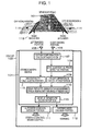
- FIG 7 is a perspective view of the coordinate system defined in FIG. 5 .
- the value zk' of z when xk and zk are substituted into the vehicular road surface equation, ax + by + cz + d 0, is found.
- zk' and zk are compared. When zk > zk', it is determined that Pk is at a position higher than the vehicular road surface equation (position of an object 703). Conversely, when zk ⁇ zk', it is determined that Pk is at a position lower than the vehicular road surface equation (position of an object 702).
- Plow be the Pk's judged to be at positions lower than the vehicular road surface equation. Take the Plow as the output from the height difference calculating portion 109 by giving the coordinate values (uk, vk) on the left image and the three-dimensional positions (xk, yk, zk) of the Plow to the pixels of the Plow.
- the coordinate values (uk, yk) on the left image are the coordinate system shown in FIG. 10 .
- the three-dimensional positions (xk, yk, zk) are the coordinate system shown in FIG 7 .
- the Plow's of the Pk's judged to be at positions lower than the vehicular road surface equation extracted by the height difference calculating portion 109 are clustered. That is, the three-dimensional positions (xk, yk, zk) possessed by the Plow's are compared. Those having close values of xk, yk, and zk are grouped together. A group having group elements exceeding some number N is extracted as an off-road group, i.e., Plow group, lower than the vehicular road surface.
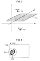
- FIG 8 shows a group of pixels extracted as the off-road group, i.e., Plow group, lower than the vehicular road surface on the left image 902.
- a portion 801 surrounded by the dotted line is one group.
- the contour line 802 is next found on the left image 902.
- the coordinate values (uk, vk) possessed by the pixels of the Plow group are utilized.
- Pixels having the same vk values are extracted.
- Pixels having a minimum vk and a maximum uk out of the extracted group of pixels are extracted as contour elements.
- the values of vk are scanned.
- the contour elements are extracted.
- the group of the extracted contour elements is taken as the contour line 802 of the Plow group.
- a contour line 802 is a contour line extracted in the left image 902.
- the contour line 802 exists in the left half of the left image 902
- pixels extracted as a contour include pixels having the same value of vk
- pixels having larger values of uk are extracted as pixels forming candidate road shoulders defining off-road regions lower than the vehicular road surface.
- Pixels 1201 surrounded by the dotted line in FIG 12 correspond to it.
- the contour line 802 exists in the right half of the left image 902
- pixels extracted as a contour include pixels having the same value of vk
- pixels having smaller values of uk are extracted as pixels forming candidate road shoulders defining off-road regions lower than the vehicular road surface.
- road shoulders defining off-road regions lower than the vehicular road surface can be detected even in processing performed by a discontinuity calculating portion 115.
- the discontinuity indicates a case where the continuities of polygons approximating a road surface around the subject vehicle are judged to have discontinuities equal to or greater than a certain threshold value.
- a distance image calculated by the distance calculating portion 107 is approximated by a plurality of polygonal regions regarding data around the subject vehicle (divided into plural image regions) as shown in FIG 13 .
- portions of the vehicular road surface 101 are shown to be approximated by four quadrilateral patches (regions 1301-1304). Portions of off-road regions 114 are shown to be approximated by four quadrilateral patches (regions 1305-1308).
- the quadrilateral patches may be replaced by triangular patches.
- the continuity between any two adjacent ones of them is judged.
- the distance between their sides closest to each other is calculated. Where the calculated distance is equal to or less than a certain threshold value, the tetragons are judged as continuous. Conversely, where the distance is equal to or greater than the certain threshold value, the tetragons are judged as discontinuous.
- the regions are judged as discontinuous and a portion indicated by 113 can be judged as a road shoulder.
- the off-road region 114 may be higher than the surface of the vehicular road 101 in some cases and may be lower than the surface of the vehicular road 101 in other cases.
- the road shoulder decision portion 110 determines that road shoulders occurring in a case where the off-road regions are lower than the vehicular road surface exist.
- the vehicle departure decision portion 116 receives the result of the decision from the road shoulder decision portion 110 of the stereo camera device 104.
- the contents of the received decision result include a decision as to whether there are the road shoulders 113 on the right and left of the vehicular road 101 ahead of the vehicle occurring in a case where the off-road regions 114 are lower than the surface of the vehicular road 101, as well as the relative position between the road shoulders 113 and the vehicle 103 in a case where there are the road shoulders 113 occurring in a case where the off-road regions 114 are lower than the vehicular road surface.
- the vehicle departure decision portion 116 makes a decision as to whether the vehicle is in danger of running off the road taking account of the relative positions with the road shoulders 113 occurring in a case where the received off-road regions 114 are lower than the vehicular road surface, the speed of the subject vehicle, and the direction of motion of the subject vehicle (steering angle), and sends the results to the automatic control decision portion 111.
- the automatic control decision portion 111 makes a decision as to whether automatic steering control or automatic brake control for preventing the vehicle from running off the road is needed. If necessary, the automatic control decision portion 111 judges the degree of control. The decision portion 111 sends instructions for control to the vehicle controller and performs steering control or brake control.
- the stereo camera device 104 has a function of detecting white lines on the road shoulders 113, guardrails, or the like rather than only the road shoulders 113 occurring where the off-road regions 114 are lower than the vehicular road surface.
- the detection can be accomplished by the technique of patent literature 1 or the like. Based on detected information, automatic control for preventing the vehicle from running off the road is possible. At this time, where road shoulders occurring where the off-road regions are lower than the vehicular road surface are detected in a manner according to the present invention, the steering control or brake control for preventing the vehicle from running off the road is exerted more strongly than where a white line or a guardrail is detected.
- the warning need decision portion 112 makes a decision as to whether it is better to give a warning to the driver about road departure of the vehicle taking account of the relative position with the road shoulders 113 occurring in a case where the off-road regions 114 are lower than the vehicular road surface, the speed of the subject vehicle, and the direction of motion of the subject vehicle (steering angle), based on the result of the decision received from the vehicle departure decision portion 116, and sends instructions to the HMI (human-machine interface) to give a warning to the driver.
- HMI human-machine interface
- the degree of warning for preventing the vehicle from running off the road is similarly increased compared with the case where a white line or a guardrail is detected.
- the present invention can replace the stereo camera device 104 of FIG 1 by a laser range finder.
- the laser range finder can obtain surrounding three-dimensional positional information, can obtain output similarly to the distance information calculating portion 107, and can detect a road shoulder defining an off-road region lower than a vehicular road surface.
Landscapes
- Engineering & Computer Science (AREA)
- Physics & Mathematics (AREA)
- General Physics & Mathematics (AREA)
- Theoretical Computer Science (AREA)
- Computer Vision & Pattern Recognition (AREA)
- Multimedia (AREA)
- Traffic Control Systems (AREA)
- Image Processing (AREA)
- Image Analysis (AREA)
- Steering Control In Accordance With Driving Conditions (AREA)
Applications Claiming Priority (2)
| Application Number | Priority Date | Filing Date | Title |
|---|---|---|---|
| JP2009296670A JP5325765B2 (ja) | 2009-12-28 | 2009-12-28 | 路肩検出装置及び路肩検出装置を用いた車両 |
| PCT/JP2010/063483 WO2011080943A1 (fr) | 2009-12-28 | 2010-08-09 | Dispositif de détection d'accotement de route et véhicule utilisant un dispositif de détection d'accotement de route |
Publications (3)
| Publication Number | Publication Date |
|---|---|
| EP2521111A1 true EP2521111A1 (fr) | 2012-11-07 |
| EP2521111A4 EP2521111A4 (fr) | 2014-01-22 |
| EP2521111B1 EP2521111B1 (fr) | 2021-10-06 |
Family
ID=44226364
Family Applications (1)
| Application Number | Title | Priority Date | Filing Date |
|---|---|---|---|
| EP10840802.2A Active EP2521111B1 (fr) | 2009-12-28 | 2010-08-09 | Dispositif de détection d'accotement de route et véhicule utilisant un dispositif de détection d'accotement de route |
Country Status (4)
| Country | Link |
|---|---|
| US (1) | US8873803B2 (fr) |
| EP (1) | EP2521111B1 (fr) |
| JP (1) | JP5325765B2 (fr) |
| WO (1) | WO2011080943A1 (fr) |
Cited By (5)
| Publication number | Priority date | Publication date | Assignee | Title |
|---|---|---|---|---|
| WO2014127777A3 (fr) * | 2013-02-19 | 2014-12-24 | Conti Temic Microelectronic Gmbh | Procédé et dispositif pour déterminer l'état d'une voie de circulation |
| US9643617B2 (en) | 2012-12-20 | 2017-05-09 | Continental Teves Ag & Co. Ohg | Friction coefficient estimation from camera and wheel speed data |
| US9676331B2 (en) | 2012-12-20 | 2017-06-13 | Continental Teves Ag & Co. Ohg | Method for determining a state of a pavement from surroundings sensor data |
| CN109649387A (zh) * | 2017-10-12 | 2019-04-19 | 德尔福技术公司 | 避免道路中的隆起所导致的轨迹偏斜的自动化车辆系统 |
| US10289920B2 (en) | 2013-11-15 | 2019-05-14 | Continental Teves Ag & Co. Ohg | Method and device for determining a roadway state by means of a vehicle camera system |
Families Citing this family (27)
| Publication number | Priority date | Publication date | Assignee | Title |
|---|---|---|---|---|
| WO2012135018A2 (fr) * | 2011-03-25 | 2012-10-04 | Tk Holdings Inc. | Système et procédé pour déterminer la vigilance d'un conducteur |
| JP5952611B2 (ja) * | 2012-03-28 | 2016-07-13 | 国立研究開発法人農業・食品産業技術総合研究機構 | 走行制御装置 |
| DE102012109310A1 (de) * | 2012-10-01 | 2014-04-03 | Conti Temic Microelectronic Gmbh | Verfahren und Vorrichtung zum Unterstützen des Zurückführens eines Fahrzeugs nach dem Verlassen einer Fahrbahn |
| US9915546B2 (en) * | 2013-05-17 | 2018-03-13 | Telenav, Inc. | Navigation system with route correction mechanism and method of operation thereof |
| JP6084552B2 (ja) * | 2013-11-06 | 2017-02-22 | 株式会社パスコ | 路面オルソ画像の生成装置および生成方法 |
| US10099724B2 (en) * | 2014-01-21 | 2018-10-16 | Continental Automotive Systems, Inc. | Road departure protection system |
| JP5874756B2 (ja) * | 2014-02-07 | 2016-03-02 | トヨタ自動車株式会社 | 区画線検出システム及び区画線検出方法 |
| JP6374695B2 (ja) * | 2014-04-28 | 2018-08-15 | 日立建機株式会社 | 路肩検出システムおよび鉱山用運搬車両 |
| DE112014006767B4 (de) * | 2014-06-25 | 2021-02-04 | Mitsubishi Electric Corporation | Gerät zum Erstellen eines Strukturschablonenmessdiagramms oder Strukturschablonenmessdiagrammdaten und Verfahren hierfür |
| JP6156400B2 (ja) * | 2015-02-09 | 2017-07-05 | トヨタ自動車株式会社 | 走行路面検出装置及び走行路面検出方法 |
| EP3217374A1 (fr) * | 2016-03-10 | 2017-09-13 | Volvo Car Corporation | Procédé et système pour estimer une limite du domaine technique d'une route |
| US10670418B2 (en) * | 2016-05-04 | 2020-06-02 | International Business Machines Corporation | Video based route recognition |
| JP6838340B2 (ja) * | 2016-09-30 | 2021-03-03 | アイシン精機株式会社 | 周辺監視装置 |
| JP6547969B2 (ja) * | 2016-11-30 | 2019-07-24 | トヨタ自動車株式会社 | 車両運転支援装置 |
| JP6794243B2 (ja) * | 2016-12-19 | 2020-12-02 | 日立オートモティブシステムズ株式会社 | 物体検出装置 |
| KR102245115B1 (ko) | 2017-02-24 | 2021-04-28 | 히다치 아스테모 가부시키가이샤 | 차량 거동 제어 장치 |
| JP6936098B2 (ja) * | 2017-09-29 | 2021-09-15 | トヨタ自動車株式会社 | 対象物推定装置 |
| CN113365855A (zh) | 2019-01-28 | 2021-09-07 | 日立安斯泰莫株式会社 | 车辆行为装置 |
| JP6913716B2 (ja) * | 2019-07-17 | 2021-08-04 | 本田技研工業株式会社 | 車両制御装置、車両制御方法、及びプログラム |
| CN111104908A (zh) * | 2019-12-20 | 2020-05-05 | 北京三快在线科技有限公司 | 一种道路边沿确定方法及装置 |
| US11511576B2 (en) * | 2020-01-24 | 2022-11-29 | Ford Global Technologies, Llc | Remote trailer maneuver assist system |
| KR20210124603A (ko) * | 2020-04-06 | 2021-10-15 | 현대자동차주식회사 | 차량의 자율 주행 제어 장치, 그를 포함한 시스템 및 그 방법 |
| JP7446434B2 (ja) | 2020-07-31 | 2024-03-08 | 日立Astemo株式会社 | サスペンション制御装置およびサスペンション装置の制御方法 |
| CN114612736A (zh) * | 2020-12-08 | 2022-06-10 | 广州汽车集团股份有限公司 | 一种车道线检测方法、系统及计算机可读介质 |
| CN113232662B (zh) * | 2021-06-22 | 2022-05-17 | 新石器慧通(北京)科技有限公司 | 一种路肩停车辅助方法及装置 |
| US11541910B1 (en) * | 2022-01-07 | 2023-01-03 | Plusai, Inc. | Methods and apparatus for navigation of an autonomous vehicle based on a location of the autonomous vehicle relative to shouldered objects |
| US11840257B2 (en) * | 2022-03-25 | 2023-12-12 | Embark Trucks Inc. | Lane change determination for vehicle on shoulder |
Citations (2)
| Publication number | Priority date | Publication date | Assignee | Title |
|---|---|---|---|---|
| US7046822B1 (en) * | 1999-06-11 | 2006-05-16 | Daimlerchrysler Ag | Method of detecting objects within a wide range of a road vehicle |
| US20060132295A1 (en) * | 2004-11-26 | 2006-06-22 | Axel Gern | Lane-departure warning system with differentiation between an edge-of-lane marking and a structural boundary of the edge of the lane |
Family Cites Families (20)
| Publication number | Priority date | Publication date | Assignee | Title |
|---|---|---|---|---|
| JP3508213B2 (ja) * | 1994-06-27 | 2004-03-22 | マツダ株式会社 | 自動車の走行状態判定装置 |
| JP3516856B2 (ja) | 1998-01-30 | 2004-04-05 | 富士重工業株式会社 | 車外監視装置 |
| JP3072730B2 (ja) * | 1998-10-09 | 2000-08-07 | 日本電気株式会社 | 車両検出方法および装置 |
| JP3897337B2 (ja) * | 2002-02-08 | 2007-03-22 | 株式会社東芝 | 路肩検出装置及び方法 |
| ES2391556T3 (es) * | 2002-05-03 | 2012-11-27 | Donnelly Corporation | Sistema de detección de objetos para vehículo |
| JP3982483B2 (ja) * | 2003-11-13 | 2007-09-26 | 日産自動車株式会社 | 車線逸脱防止装置 |
| US8594370B2 (en) * | 2004-07-26 | 2013-11-26 | Automotive Systems Laboratory, Inc. | Vulnerable road user protection system |
| JP4835201B2 (ja) * | 2006-02-27 | 2011-12-14 | トヨタ自動車株式会社 | 立体形状検出装置 |
| JP2007331652A (ja) * | 2006-06-16 | 2007-12-27 | Toyota Motor Corp | 車両停止装置 |
| JP4857951B2 (ja) | 2006-06-27 | 2012-01-18 | パナソニック電工株式会社 | マッサージ機 |
| JP5223675B2 (ja) * | 2006-08-18 | 2013-06-26 | 日本電気株式会社 | 車両検知装置,車両検知方法並びに車両検知プログラム |
| US8224564B2 (en) * | 2007-02-14 | 2012-07-17 | Fuji Jukogyo Kabushiki Kaisha | Vehicle drive assist system |
| JP2009053818A (ja) * | 2007-08-24 | 2009-03-12 | Toshiba Corp | 画像処理装置及びその方法 |
| US8436902B2 (en) * | 2007-08-30 | 2013-05-07 | Valeo Schalter And Sensoren Gmbh | Method and system for weather condition detection with image-based road characterization |
| JP2009139323A (ja) * | 2007-12-10 | 2009-06-25 | Mazda Motor Corp | 車両用走行路面検出装置 |
| JP2010055340A (ja) * | 2008-08-28 | 2010-03-11 | Hirosaki Univ | 走行路推定装置及びプログラム |
| US8384532B2 (en) * | 2009-04-02 | 2013-02-26 | GM Global Technology Operations LLC | Lane of travel on windshield head-up display |
| US8269652B2 (en) * | 2009-04-02 | 2012-09-18 | GM Global Technology Operations LLC | Vehicle-to-vehicle communicator on full-windshield head-up display |
| US8395529B2 (en) * | 2009-04-02 | 2013-03-12 | GM Global Technology Operations LLC | Traffic infrastructure indicator on head-up display |
| US8611692B2 (en) * | 2011-09-26 | 2013-12-17 | Northrop Grumman Systems Corporation | Automated image registration with varied amounts of a priori information using a minimum entropy method |
-
2009
- 2009-12-28 JP JP2009296670A patent/JP5325765B2/ja active Active
-
2010
- 2010-08-09 WO PCT/JP2010/063483 patent/WO2011080943A1/fr active Application Filing
- 2010-08-09 EP EP10840802.2A patent/EP2521111B1/fr active Active
- 2010-08-09 US US13/519,347 patent/US8873803B2/en active Active
Patent Citations (2)
| Publication number | Priority date | Publication date | Assignee | Title |
|---|---|---|---|---|
| US7046822B1 (en) * | 1999-06-11 | 2006-05-16 | Daimlerchrysler Ag | Method of detecting objects within a wide range of a road vehicle |
| US20060132295A1 (en) * | 2004-11-26 | 2006-06-22 | Axel Gern | Lane-departure warning system with differentiation between an edge-of-lane marking and a structural boundary of the edge of the lane |
Non-Patent Citations (3)
| Title |
|---|
| ANDREAS WEDEL ET AL: "B-spline modeling of road surfaces for freespace estimation", INTELLIGENT VEHICLES SYMPOSIUM, 2008 IEEE, IEEE, PISCATAWAY, NJ, USA, 4 June 2008 (2008-06-04), pages 828-833, XP031318899, ISBN: 978-1-4244-2568-6 * |
| HOFF W ET AL: "Surfaces from stereo: integrating feature matching, disparity estimation, and contour detection", TRANSACTIONS ON PATTERN ANALYSIS AND MACHINE INTELLIGENCE, IEEE, PISCATAWAY, USA, vol. 11, no. 2, 1 February 1989 (1989-02-01), pages 121-135, XP011478204, ISSN: 0162-8828, DOI: 10.1109/34.16709 * |
| See also references of WO2011080943A1 * |
Cited By (7)
| Publication number | Priority date | Publication date | Assignee | Title |
|---|---|---|---|---|
| US9643617B2 (en) | 2012-12-20 | 2017-05-09 | Continental Teves Ag & Co. Ohg | Friction coefficient estimation from camera and wheel speed data |
| US9676331B2 (en) | 2012-12-20 | 2017-06-13 | Continental Teves Ag & Co. Ohg | Method for determining a state of a pavement from surroundings sensor data |
| WO2014127777A3 (fr) * | 2013-02-19 | 2014-12-24 | Conti Temic Microelectronic Gmbh | Procédé et dispositif pour déterminer l'état d'une voie de circulation |
| US10147002B2 (en) | 2013-02-19 | 2018-12-04 | Conti Temic Microelectronic Gmbh | Method and apparatus for determining a road condition |
| US10289920B2 (en) | 2013-11-15 | 2019-05-14 | Continental Teves Ag & Co. Ohg | Method and device for determining a roadway state by means of a vehicle camera system |
| CN109649387A (zh) * | 2017-10-12 | 2019-04-19 | 德尔福技术公司 | 避免道路中的隆起所导致的轨迹偏斜的自动化车辆系统 |
| CN109649387B (zh) * | 2017-10-12 | 2022-01-11 | 安波福技术有限公司 | 避免道路中的隆起所导致的轨迹偏斜的自动化车辆系统 |
Also Published As
| Publication number | Publication date |
|---|---|
| US8873803B2 (en) | 2014-10-28 |
| WO2011080943A1 (fr) | 2011-07-07 |
| EP2521111B1 (fr) | 2021-10-06 |
| JP2011138244A (ja) | 2011-07-14 |
| US20120288154A1 (en) | 2012-11-15 |
| EP2521111A4 (fr) | 2014-01-22 |
| JP5325765B2 (ja) | 2013-10-23 |
Similar Documents
| Publication | Publication Date | Title |
|---|---|---|
| EP2521111B1 (fr) | Dispositif de détection d'accotement de route et véhicule utilisant un dispositif de détection d'accotement de route | |
| US9074906B2 (en) | Road shape recognition device | |
| US6734787B2 (en) | Apparatus and method of recognizing vehicle travelling behind | |
| US9809223B2 (en) | Driving assistant for vehicles | |
| KR100941271B1 (ko) | 자동차용 차선이탈 방지 방법 | |
| EP1564703B1 (fr) | Système d'assistance de conduite pour véhicules | |
| US9704047B2 (en) | Moving object recognition apparatus | |
| JP4775391B2 (ja) | 障害物検出装置 | |
| JP5712119B2 (ja) | 車両用歩行者報知装置 | |
| EP3188118A1 (fr) | Dispositif de détection d'objet | |
| JP6313081B2 (ja) | 車載用画像処理装置およびそれを用いた車両システム | |
| JP2008123462A (ja) | 物体検知装置 | |
| JPH1139596A (ja) | 車外監視装置 | |
| JP3872179B2 (ja) | 車両の衝突防止装置 | |
| US10672141B2 (en) | Device, method, system and computer-readable medium for determining collision target object rejection | |
| JP2021513159A (ja) | 車線を変更するときに、自動車両と、車両の隣の走行車線にある2次物体との間の衝突リスクを検知するためのシステムおよび方法 | |
| JP3666332B2 (ja) | 歩行者検知装置 | |
| CN109522779B (zh) | 图像处理装置 | |
| KR101721442B1 (ko) | 차량용 블랙박스 후방카메라를 이용한 측후방 충돌방지 시스템 및 충돌방지방법 | |
| JP2017129543A (ja) | ステレオカメラ装置及び車両 | |
| JP6690510B2 (ja) | 物体認識装置 | |
| JP3586938B2 (ja) | 車載用距離測定装置 | |
| JP2007310591A (ja) | 画像処理装置及び駐車場判定方法 | |
| KR20160133386A (ko) | 차량용 블랙박스 후방카메라를 이용한 측후방 충돌방지 시스템의 충돌방지방법 | |
| EP3540643A1 (fr) | Appareil de traitement d'images et procédé de traitement d'images |
Legal Events
| Date | Code | Title | Description |
|---|---|---|---|
| PUAI | Public reference made under article 153(3) epc to a published international application that has entered the european phase |
Free format text: ORIGINAL CODE: 0009012 |
|
| 17P | Request for examination filed |
Effective date: 20120730 |
|
| AK | Designated contracting states |
Kind code of ref document: A1 Designated state(s): AL AT BE BG CH CY CZ DE DK EE ES FI FR GB GR HR HU IE IS IT LI LT LU LV MC MK MT NL NO PL PT RO SE SI SK SM TR |
|
| DAX | Request for extension of the european patent (deleted) | ||
| A4 | Supplementary search report drawn up and despatched |
Effective date: 20140107 |
|
| RIC1 | Information provided on ipc code assigned before grant |
Ipc: G08G 1/16 20060101AFI20131219BHEP Ipc: G06T 1/00 20060101ALI20131219BHEP Ipc: G06K 9/00 20060101ALI20131219BHEP Ipc: G06T 7/00 20060101ALI20131219BHEP Ipc: B60W 30/10 20060101ALI20131219BHEP Ipc: B60W 30/12 20060101ALI20131219BHEP |
|
| STAA | Information on the status of an ep patent application or granted ep patent |
Free format text: STATUS: EXAMINATION IS IN PROGRESS |
|
| 17Q | First examination report despatched |
Effective date: 20171115 |
|
| STAA | Information on the status of an ep patent application or granted ep patent |
Free format text: STATUS: EXAMINATION IS IN PROGRESS |
|
| RIC1 | Information provided on ipc code assigned before grant |
Ipc: G06T 7/136 20170101ALI20210408BHEP Ipc: G06T 7/174 20170101ALI20210408BHEP Ipc: G06T 7/11 20170101ALI20210408BHEP Ipc: B60W 30/10 20060101ALI20210408BHEP Ipc: G06T 1/00 20060101ALI20210408BHEP Ipc: G06K 9/00 20060101ALI20210408BHEP Ipc: G06T 7/00 20170101ALI20210408BHEP Ipc: B60W 30/12 20200101ALI20210408BHEP Ipc: G08G 1/16 20060101AFI20210408BHEP |
|
| GRAP | Despatch of communication of intention to grant a patent |
Free format text: ORIGINAL CODE: EPIDOSNIGR1 |
|
| STAA | Information on the status of an ep patent application or granted ep patent |
Free format text: STATUS: GRANT OF PATENT IS INTENDED |
|
| INTG | Intention to grant announced |
Effective date: 20210525 |
|
| RIN1 | Information on inventor provided before grant (corrected) |
Inventor name: NAKA TAKUYA Inventor name: MONJI TATSUHIKO Inventor name: MURAMATSU SHOJI Inventor name: HIGUCHI MIRAI Inventor name: SHIMA TAKESHI |
|
| GRAS | Grant fee paid |
Free format text: ORIGINAL CODE: EPIDOSNIGR3 |
|
| GRAA | (expected) grant |
Free format text: ORIGINAL CODE: 0009210 |
|
| STAA | Information on the status of an ep patent application or granted ep patent |
Free format text: STATUS: THE PATENT HAS BEEN GRANTED |
|
| RIN1 | Information on inventor provided before grant (corrected) |
Inventor name: NAKA TAKUYA Inventor name: MONJI TATSUHIKO Inventor name: MURAMATSU SHOJI Inventor name: HIGUCHI MIRAI Inventor name: SHIMA TAKESHI |
|
| RAP3 | Party data changed (applicant data changed or rights of an application transferred) |
Owner name: HITACHI ASTEMO, LTD. |
|
| AK | Designated contracting states |
Kind code of ref document: B1 Designated state(s): AL AT BE BG CH CY CZ DE DK EE ES FI FR GB GR HR HU IE IS IT LI LT LU LV MC MK MT NL NO PL PT RO SE SI SK SM TR |
|
| REG | Reference to a national code |
Ref country code: GB Ref legal event code: FG4D |
|
| REG | Reference to a national code |
Ref country code: CH Ref legal event code: EP Ref country code: AT Ref legal event code: REF Ref document number: 1436900 Country of ref document: AT Kind code of ref document: T Effective date: 20211015 |
|
| REG | Reference to a national code |
Ref country code: IE Ref legal event code: FG4D |
|
| REG | Reference to a national code |
Ref country code: DE Ref legal event code: R096 Ref document number: 602010067659 Country of ref document: DE |
|
| REG | Reference to a national code |
Ref country code: LT Ref legal event code: MG9D |
|
| REG | Reference to a national code |
Ref country code: NL Ref legal event code: MP Effective date: 20211006 |
|
| REG | Reference to a national code |
Ref country code: AT Ref legal event code: MK05 Ref document number: 1436900 Country of ref document: AT Kind code of ref document: T Effective date: 20211006 |
|
| PG25 | Lapsed in a contracting state [announced via postgrant information from national office to epo] |
Ref country code: LT Free format text: LAPSE BECAUSE OF FAILURE TO SUBMIT A TRANSLATION OF THE DESCRIPTION OR TO PAY THE FEE WITHIN THE PRESCRIBED TIME-LIMIT Effective date: 20211006 Ref country code: FI Free format text: LAPSE BECAUSE OF FAILURE TO SUBMIT A TRANSLATION OF THE DESCRIPTION OR TO PAY THE FEE WITHIN THE PRESCRIBED TIME-LIMIT Effective date: 20211006 Ref country code: BG Free format text: LAPSE BECAUSE OF FAILURE TO SUBMIT A TRANSLATION OF THE DESCRIPTION OR TO PAY THE FEE WITHIN THE PRESCRIBED TIME-LIMIT Effective date: 20220106 Ref country code: AT Free format text: LAPSE BECAUSE OF FAILURE TO SUBMIT A TRANSLATION OF THE DESCRIPTION OR TO PAY THE FEE WITHIN THE PRESCRIBED TIME-LIMIT Effective date: 20211006 |
|
| PG25 | Lapsed in a contracting state [announced via postgrant information from national office to epo] |
Ref country code: IS Free format text: LAPSE BECAUSE OF FAILURE TO SUBMIT A TRANSLATION OF THE DESCRIPTION OR TO PAY THE FEE WITHIN THE PRESCRIBED TIME-LIMIT Effective date: 20220206 Ref country code: SE Free format text: LAPSE BECAUSE OF FAILURE TO SUBMIT A TRANSLATION OF THE DESCRIPTION OR TO PAY THE FEE WITHIN THE PRESCRIBED TIME-LIMIT Effective date: 20211006 Ref country code: PT Free format text: LAPSE BECAUSE OF FAILURE TO SUBMIT A TRANSLATION OF THE DESCRIPTION OR TO PAY THE FEE WITHIN THE PRESCRIBED TIME-LIMIT Effective date: 20220207 Ref country code: PL Free format text: LAPSE BECAUSE OF FAILURE TO SUBMIT A TRANSLATION OF THE DESCRIPTION OR TO PAY THE FEE WITHIN THE PRESCRIBED TIME-LIMIT Effective date: 20211006 Ref country code: NO Free format text: LAPSE BECAUSE OF FAILURE TO SUBMIT A TRANSLATION OF THE DESCRIPTION OR TO PAY THE FEE WITHIN THE PRESCRIBED TIME-LIMIT Effective date: 20220106 Ref country code: NL Free format text: LAPSE BECAUSE OF FAILURE TO SUBMIT A TRANSLATION OF THE DESCRIPTION OR TO PAY THE FEE WITHIN THE PRESCRIBED TIME-LIMIT Effective date: 20211006 Ref country code: LV Free format text: LAPSE BECAUSE OF FAILURE TO SUBMIT A TRANSLATION OF THE DESCRIPTION OR TO PAY THE FEE WITHIN THE PRESCRIBED TIME-LIMIT Effective date: 20211006 Ref country code: HR Free format text: LAPSE BECAUSE OF FAILURE TO SUBMIT A TRANSLATION OF THE DESCRIPTION OR TO PAY THE FEE WITHIN THE PRESCRIBED TIME-LIMIT Effective date: 20211006 Ref country code: GR Free format text: LAPSE BECAUSE OF FAILURE TO SUBMIT A TRANSLATION OF THE DESCRIPTION OR TO PAY THE FEE WITHIN THE PRESCRIBED TIME-LIMIT Effective date: 20220107 Ref country code: ES Free format text: LAPSE BECAUSE OF FAILURE TO SUBMIT A TRANSLATION OF THE DESCRIPTION OR TO PAY THE FEE WITHIN THE PRESCRIBED TIME-LIMIT Effective date: 20211006 |
|
| REG | Reference to a national code |
Ref country code: DE Ref legal event code: R097 Ref document number: 602010067659 Country of ref document: DE |
|
| PG25 | Lapsed in a contracting state [announced via postgrant information from national office to epo] |
Ref country code: SM Free format text: LAPSE BECAUSE OF FAILURE TO SUBMIT A TRANSLATION OF THE DESCRIPTION OR TO PAY THE FEE WITHIN THE PRESCRIBED TIME-LIMIT Effective date: 20211006 Ref country code: SK Free format text: LAPSE BECAUSE OF FAILURE TO SUBMIT A TRANSLATION OF THE DESCRIPTION OR TO PAY THE FEE WITHIN THE PRESCRIBED TIME-LIMIT Effective date: 20211006 Ref country code: RO Free format text: LAPSE BECAUSE OF FAILURE TO SUBMIT A TRANSLATION OF THE DESCRIPTION OR TO PAY THE FEE WITHIN THE PRESCRIBED TIME-LIMIT Effective date: 20211006 Ref country code: EE Free format text: LAPSE BECAUSE OF FAILURE TO SUBMIT A TRANSLATION OF THE DESCRIPTION OR TO PAY THE FEE WITHIN THE PRESCRIBED TIME-LIMIT Effective date: 20211006 Ref country code: DK Free format text: LAPSE BECAUSE OF FAILURE TO SUBMIT A TRANSLATION OF THE DESCRIPTION OR TO PAY THE FEE WITHIN THE PRESCRIBED TIME-LIMIT Effective date: 20211006 Ref country code: CZ Free format text: LAPSE BECAUSE OF FAILURE TO SUBMIT A TRANSLATION OF THE DESCRIPTION OR TO PAY THE FEE WITHIN THE PRESCRIBED TIME-LIMIT Effective date: 20211006 |
|
| PLBE | No opposition filed within time limit |
Free format text: ORIGINAL CODE: 0009261 |
|
| STAA | Information on the status of an ep patent application or granted ep patent |
Free format text: STATUS: NO OPPOSITION FILED WITHIN TIME LIMIT |
|
| 26N | No opposition filed |
Effective date: 20220707 |
|
| PG25 | Lapsed in a contracting state [announced via postgrant information from national office to epo] |
Ref country code: AL Free format text: LAPSE BECAUSE OF FAILURE TO SUBMIT A TRANSLATION OF THE DESCRIPTION OR TO PAY THE FEE WITHIN THE PRESCRIBED TIME-LIMIT Effective date: 20211006 |
|
| PG25 | Lapsed in a contracting state [announced via postgrant information from national office to epo] |
Ref country code: SI Free format text: LAPSE BECAUSE OF FAILURE TO SUBMIT A TRANSLATION OF THE DESCRIPTION OR TO PAY THE FEE WITHIN THE PRESCRIBED TIME-LIMIT Effective date: 20211006 |
|
| PG25 | Lapsed in a contracting state [announced via postgrant information from national office to epo] |
Ref country code: MC Free format text: LAPSE BECAUSE OF FAILURE TO SUBMIT A TRANSLATION OF THE DESCRIPTION OR TO PAY THE FEE WITHIN THE PRESCRIBED TIME-LIMIT Effective date: 20211006 |
|
| REG | Reference to a national code |
Ref country code: CH Ref legal event code: PL |
|
| GBPC | Gb: european patent ceased through non-payment of renewal fee |
Effective date: 20220809 |
|
| PG25 | Lapsed in a contracting state [announced via postgrant information from national office to epo] |
Ref country code: LU Free format text: LAPSE BECAUSE OF NON-PAYMENT OF DUE FEES Effective date: 20220809 Ref country code: LI Free format text: LAPSE BECAUSE OF NON-PAYMENT OF DUE FEES Effective date: 20220831 Ref country code: CH Free format text: LAPSE BECAUSE OF NON-PAYMENT OF DUE FEES Effective date: 20220831 |
|
| REG | Reference to a national code |
Ref country code: BE Ref legal event code: MM Effective date: 20220831 |
|
| PG25 | Lapsed in a contracting state [announced via postgrant information from national office to epo] |
Ref country code: IT Free format text: LAPSE BECAUSE OF FAILURE TO SUBMIT A TRANSLATION OF THE DESCRIPTION OR TO PAY THE FEE WITHIN THE PRESCRIBED TIME-LIMIT Effective date: 20211006 |
|
| PG25 | Lapsed in a contracting state [announced via postgrant information from national office to epo] |
Ref country code: IE Free format text: LAPSE BECAUSE OF NON-PAYMENT OF DUE FEES Effective date: 20220809 Ref country code: FR Free format text: LAPSE BECAUSE OF NON-PAYMENT OF DUE FEES Effective date: 20220831 |
|
| PG25 | Lapsed in a contracting state [announced via postgrant information from national office to epo] |
Ref country code: BE Free format text: LAPSE BECAUSE OF NON-PAYMENT OF DUE FEES Effective date: 20220831 |
|
| PG25 | Lapsed in a contracting state [announced via postgrant information from national office to epo] |
Ref country code: GB Free format text: LAPSE BECAUSE OF NON-PAYMENT OF DUE FEES Effective date: 20220809 |
|
| PGFP | Annual fee paid to national office [announced via postgrant information from national office to epo] |
Ref country code: DE Payment date: 20230627 Year of fee payment: 14 |
|
| PG25 | Lapsed in a contracting state [announced via postgrant information from national office to epo] |
Ref country code: HU Free format text: LAPSE BECAUSE OF FAILURE TO SUBMIT A TRANSLATION OF THE DESCRIPTION OR TO PAY THE FEE WITHIN THE PRESCRIBED TIME-LIMIT; INVALID AB INITIO Effective date: 20100809 |
|
| PG25 | Lapsed in a contracting state [announced via postgrant information from national office to epo] |
Ref country code: CY Free format text: LAPSE BECAUSE OF FAILURE TO SUBMIT A TRANSLATION OF THE DESCRIPTION OR TO PAY THE FEE WITHIN THE PRESCRIBED TIME-LIMIT Effective date: 20211006 |