EP2518317A1 - Doppelvakuumpumpenvorrichtung, gasreinigungssystem mit der doppelvakuumpumpenvorrichtung und abgasvibrationsunterdrückungsvorrichtung in der doppelvakuumpumpenvorrichtung - Google Patents
Doppelvakuumpumpenvorrichtung, gasreinigungssystem mit der doppelvakuumpumpenvorrichtung und abgasvibrationsunterdrückungsvorrichtung in der doppelvakuumpumpenvorrichtung Download PDFInfo
- Publication number
- EP2518317A1 EP2518317A1 EP10839437A EP10839437A EP2518317A1 EP 2518317 A1 EP2518317 A1 EP 2518317A1 EP 10839437 A EP10839437 A EP 10839437A EP 10839437 A EP10839437 A EP 10839437A EP 2518317 A1 EP2518317 A1 EP 2518317A1
- Authority
- EP
- European Patent Office
- Prior art keywords
- vacuum pump
- gas
- buffer tube
- pump apparatus
- pressure
- Prior art date
- Legal status (The legal status is an assumption and is not a legal conclusion. Google has not performed a legal analysis and makes no representation as to the accuracy of the status listed.)
- Granted
Links
- 238000000746 purification Methods 0.000 title claims description 36
- 238000001179 sorption measurement Methods 0.000 claims description 143
- 239000003463 adsorbent Substances 0.000 claims description 22
- 230000003247 decreasing effect Effects 0.000 claims description 12
- 238000011144 upstream manufacturing Methods 0.000 claims description 11
- 238000005452 bending Methods 0.000 claims description 4
- 238000006073 displacement reaction Methods 0.000 abstract description 9
- 238000001514 detection method Methods 0.000 abstract description 2
- 239000007789 gas Substances 0.000 description 232
- 230000008929 regeneration Effects 0.000 description 62
- 238000011069 regeneration method Methods 0.000 description 62
- IJGRMHOSHXDMSA-UHFFFAOYSA-N Atomic nitrogen Chemical compound N#N IJGRMHOSHXDMSA-UHFFFAOYSA-N 0.000 description 20
- 230000000052 comparative effect Effects 0.000 description 19
- 230000007423 decrease Effects 0.000 description 17
- QVGXLLKOCUKJST-UHFFFAOYSA-N atomic oxygen Chemical group [O] QVGXLLKOCUKJST-UHFFFAOYSA-N 0.000 description 15
- 239000001301 oxygen Substances 0.000 description 15
- 229910052760 oxygen Inorganic materials 0.000 description 15
- 230000001133 acceleration Effects 0.000 description 13
- 230000003584 silencer Effects 0.000 description 13
- 238000005259 measurement Methods 0.000 description 12
- 230000008859 change Effects 0.000 description 11
- MYMOFIZGZYHOMD-UHFFFAOYSA-N Dioxygen Chemical compound O=O MYMOFIZGZYHOMD-UHFFFAOYSA-N 0.000 description 10
- 229910001882 dioxygen Inorganic materials 0.000 description 10
- 229910052757 nitrogen Inorganic materials 0.000 description 10
- 239000012535 impurity Substances 0.000 description 9
- 230000004048 modification Effects 0.000 description 9
- 238000012986 modification Methods 0.000 description 9
- 230000000694 effects Effects 0.000 description 6
- XLYOFNOQVPJJNP-UHFFFAOYSA-N water Substances O XLYOFNOQVPJJNP-UHFFFAOYSA-N 0.000 description 6
- 230000036961 partial effect Effects 0.000 description 5
- 238000007789 sealing Methods 0.000 description 5
- 230000015556 catabolic process Effects 0.000 description 4
- 238000006731 degradation reaction Methods 0.000 description 4
- 238000010586 diagram Methods 0.000 description 4
- 238000004891 communication Methods 0.000 description 3
- 238000011156 evaluation Methods 0.000 description 3
- 238000000034 method Methods 0.000 description 3
- CURLTUGMZLYLDI-UHFFFAOYSA-N Carbon dioxide Chemical compound O=C=O CURLTUGMZLYLDI-UHFFFAOYSA-N 0.000 description 2
- 238000003795 desorption Methods 0.000 description 2
- 239000000463 material Substances 0.000 description 2
- VNWKTOKETHGBQD-UHFFFAOYSA-N methane Chemical compound C VNWKTOKETHGBQD-UHFFFAOYSA-N 0.000 description 2
- 238000012360 testing method Methods 0.000 description 2
- OKTJSMMVPCPJKN-UHFFFAOYSA-N Carbon Chemical compound [C] OKTJSMMVPCPJKN-UHFFFAOYSA-N 0.000 description 1
- UGFAIRIUMAVXCW-UHFFFAOYSA-N Carbon monoxide Chemical compound [O+]#[C-] UGFAIRIUMAVXCW-UHFFFAOYSA-N 0.000 description 1
- 229910021536 Zeolite Inorganic materials 0.000 description 1
- 238000010521 absorption reaction Methods 0.000 description 1
- 230000009471 action Effects 0.000 description 1
- 230000002411 adverse Effects 0.000 description 1
- 230000002238 attenuated effect Effects 0.000 description 1
- 229910052799 carbon Inorganic materials 0.000 description 1
- 229910002092 carbon dioxide Inorganic materials 0.000 description 1
- 239000001569 carbon dioxide Substances 0.000 description 1
- 229910002091 carbon monoxide Inorganic materials 0.000 description 1
- 230000006378 damage Effects 0.000 description 1
- HNPSIPDUKPIQMN-UHFFFAOYSA-N dioxosilane;oxo(oxoalumanyloxy)alumane Chemical compound O=[Si]=O.O=[Al]O[Al]=O HNPSIPDUKPIQMN-UHFFFAOYSA-N 0.000 description 1
- 239000001257 hydrogen Substances 0.000 description 1
- 229910052739 hydrogen Inorganic materials 0.000 description 1
- 150000002431 hydrogen Chemical class 0.000 description 1
- 238000004519 manufacturing process Methods 0.000 description 1
- 230000007246 mechanism Effects 0.000 description 1
- 239000002808 molecular sieve Substances 0.000 description 1
- 230000008569 process Effects 0.000 description 1
- 230000010349 pulsation Effects 0.000 description 1
- 230000002829 reductive effect Effects 0.000 description 1
- 230000001932 seasonal effect Effects 0.000 description 1
- 239000004065 semiconductor Substances 0.000 description 1
- 238000005549 size reduction Methods 0.000 description 1
- URGAHOPLAPQHLN-UHFFFAOYSA-N sodium aluminosilicate Chemical compound [Na+].[Al+3].[O-][Si]([O-])=O.[O-][Si]([O-])=O URGAHOPLAPQHLN-UHFFFAOYSA-N 0.000 description 1
- 239000010457 zeolite Substances 0.000 description 1
Images


Classifications
-
- F—MECHANICAL ENGINEERING; LIGHTING; HEATING; WEAPONS; BLASTING
- F04—POSITIVE - DISPLACEMENT MACHINES FOR LIQUIDS; PUMPS FOR LIQUIDS OR ELASTIC FLUIDS
- F04B—POSITIVE-DISPLACEMENT MACHINES FOR LIQUIDS; PUMPS
- F04B41/00—Pumping installations or systems specially adapted for elastic fluids
- F04B41/06—Combinations of two or more pumps
-
- B—PERFORMING OPERATIONS; TRANSPORTING
- B01—PHYSICAL OR CHEMICAL PROCESSES OR APPARATUS IN GENERAL
- B01D—SEPARATION
- B01D53/00—Separation of gases or vapours; Recovering vapours of volatile solvents from gases; Chemical or biological purification of waste gases, e.g. engine exhaust gases, smoke, fumes, flue gases, aerosols
- B01D53/02—Separation of gases or vapours; Recovering vapours of volatile solvents from gases; Chemical or biological purification of waste gases, e.g. engine exhaust gases, smoke, fumes, flue gases, aerosols by adsorption, e.g. preparative gas chromatography
- B01D53/04—Separation of gases or vapours; Recovering vapours of volatile solvents from gases; Chemical or biological purification of waste gases, e.g. engine exhaust gases, smoke, fumes, flue gases, aerosols by adsorption, e.g. preparative gas chromatography with stationary adsorbents
- B01D53/0407—Constructional details of adsorbing systems
- B01D53/0446—Means for feeding or distributing gases
-
- B—PERFORMING OPERATIONS; TRANSPORTING
- B01—PHYSICAL OR CHEMICAL PROCESSES OR APPARATUS IN GENERAL
- B01D—SEPARATION
- B01D53/00—Separation of gases or vapours; Recovering vapours of volatile solvents from gases; Chemical or biological purification of waste gases, e.g. engine exhaust gases, smoke, fumes, flue gases, aerosols
- B01D53/34—Chemical or biological purification of waste gases
- B01D53/73—After-treatment of removed components
-
- B—PERFORMING OPERATIONS; TRANSPORTING
- B01—PHYSICAL OR CHEMICAL PROCESSES OR APPARATUS IN GENERAL
- B01D—SEPARATION
- B01D53/00—Separation of gases or vapours; Recovering vapours of volatile solvents from gases; Chemical or biological purification of waste gases, e.g. engine exhaust gases, smoke, fumes, flue gases, aerosols
- B01D53/34—Chemical or biological purification of waste gases
- B01D53/96—Regeneration, reactivation or recycling of reactants
-
- F—MECHANICAL ENGINEERING; LIGHTING; HEATING; WEAPONS; BLASTING
- F04—POSITIVE - DISPLACEMENT MACHINES FOR LIQUIDS; PUMPS FOR LIQUIDS OR ELASTIC FLUIDS
- F04B—POSITIVE-DISPLACEMENT MACHINES FOR LIQUIDS; PUMPS
- F04B37/00—Pumps having pertinent characteristics not provided for in, or of interest apart from, groups F04B25/00 - F04B35/00
- F04B37/10—Pumps having pertinent characteristics not provided for in, or of interest apart from, groups F04B25/00 - F04B35/00 for special use
- F04B37/14—Pumps having pertinent characteristics not provided for in, or of interest apart from, groups F04B25/00 - F04B35/00 for special use to obtain high vacuum
- F04B37/16—Means for nullifying unswept space
-
- F—MECHANICAL ENGINEERING; LIGHTING; HEATING; WEAPONS; BLASTING
- F04—POSITIVE - DISPLACEMENT MACHINES FOR LIQUIDS; PUMPS FOR LIQUIDS OR ELASTIC FLUIDS
- F04B—POSITIVE-DISPLACEMENT MACHINES FOR LIQUIDS; PUMPS
- F04B39/00—Component parts, details, or accessories, of pumps or pumping systems specially adapted for elastic fluids, not otherwise provided for in, or of interest apart from, groups F04B25/00 - F04B37/00
- F04B39/16—Filtration; Moisture separation
-
- F—MECHANICAL ENGINEERING; LIGHTING; HEATING; WEAPONS; BLASTING
- F04—POSITIVE - DISPLACEMENT MACHINES FOR LIQUIDS; PUMPS FOR LIQUIDS OR ELASTIC FLUIDS
- F04B—POSITIVE-DISPLACEMENT MACHINES FOR LIQUIDS; PUMPS
- F04B49/00—Control, e.g. of pump delivery, or pump pressure of, or safety measures for, machines, pumps, or pumping installations, not otherwise provided for, or of interest apart from, groups F04B1/00 - F04B47/00
- F04B49/007—Installations or systems with two or more pumps or pump cylinders, wherein the flow-path through the stages can be changed, e.g. from series to parallel
-
- F—MECHANICAL ENGINEERING; LIGHTING; HEATING; WEAPONS; BLASTING
- F04—POSITIVE - DISPLACEMENT MACHINES FOR LIQUIDS; PUMPS FOR LIQUIDS OR ELASTIC FLUIDS
- F04C—ROTARY-PISTON, OR OSCILLATING-PISTON, POSITIVE-DISPLACEMENT MACHINES FOR LIQUIDS; ROTARY-PISTON, OR OSCILLATING-PISTON, POSITIVE-DISPLACEMENT PUMPS
- F04C18/00—Rotary-piston pumps specially adapted for elastic fluids
- F04C18/08—Rotary-piston pumps specially adapted for elastic fluids of intermeshing-engagement type, i.e. with engagement of co-operating members similar to that of toothed gearing
- F04C18/12—Rotary-piston pumps specially adapted for elastic fluids of intermeshing-engagement type, i.e. with engagement of co-operating members similar to that of toothed gearing of other than internal-axis type
- F04C18/126—Rotary-piston pumps specially adapted for elastic fluids of intermeshing-engagement type, i.e. with engagement of co-operating members similar to that of toothed gearing of other than internal-axis type with radially from the rotor body extending elements, not necessarily co-operating with corresponding recesses in the other rotor, e.g. lobes, Roots type
-
- F—MECHANICAL ENGINEERING; LIGHTING; HEATING; WEAPONS; BLASTING
- F04—POSITIVE - DISPLACEMENT MACHINES FOR LIQUIDS; PUMPS FOR LIQUIDS OR ELASTIC FLUIDS
- F04C—ROTARY-PISTON, OR OSCILLATING-PISTON, POSITIVE-DISPLACEMENT MACHINES FOR LIQUIDS; ROTARY-PISTON, OR OSCILLATING-PISTON, POSITIVE-DISPLACEMENT PUMPS
- F04C23/00—Combinations of two or more pumps, each being of rotary-piston or oscillating-piston type, specially adapted for elastic fluids; Pumping installations specially adapted for elastic fluids; Multi-stage pumps specially adapted for elastic fluids
- F04C23/001—Combinations of two or more pumps, each being of rotary-piston or oscillating-piston type, specially adapted for elastic fluids; Pumping installations specially adapted for elastic fluids; Multi-stage pumps specially adapted for elastic fluids of similar working principle
-
- F—MECHANICAL ENGINEERING; LIGHTING; HEATING; WEAPONS; BLASTING
- F04—POSITIVE - DISPLACEMENT MACHINES FOR LIQUIDS; PUMPS FOR LIQUIDS OR ELASTIC FLUIDS
- F04C—ROTARY-PISTON, OR OSCILLATING-PISTON, POSITIVE-DISPLACEMENT MACHINES FOR LIQUIDS; ROTARY-PISTON, OR OSCILLATING-PISTON, POSITIVE-DISPLACEMENT PUMPS
- F04C25/00—Adaptations of pumps for special use of pumps for elastic fluids
- F04C25/02—Adaptations of pumps for special use of pumps for elastic fluids for producing high vacuum
-
- F—MECHANICAL ENGINEERING; LIGHTING; HEATING; WEAPONS; BLASTING
- F04—POSITIVE - DISPLACEMENT MACHINES FOR LIQUIDS; PUMPS FOR LIQUIDS OR ELASTIC FLUIDS
- F04C—ROTARY-PISTON, OR OSCILLATING-PISTON, POSITIVE-DISPLACEMENT MACHINES FOR LIQUIDS; ROTARY-PISTON, OR OSCILLATING-PISTON, POSITIVE-DISPLACEMENT PUMPS
- F04C28/00—Control of, monitoring of, or safety arrangements for, pumps or pumping installations specially adapted for elastic fluids
- F04C28/02—Control of, monitoring of, or safety arrangements for, pumps or pumping installations specially adapted for elastic fluids specially adapted for several pumps connected in series or in parallel
-
- F—MECHANICAL ENGINEERING; LIGHTING; HEATING; WEAPONS; BLASTING
- F04—POSITIVE - DISPLACEMENT MACHINES FOR LIQUIDS; PUMPS FOR LIQUIDS OR ELASTIC FLUIDS
- F04C—ROTARY-PISTON, OR OSCILLATING-PISTON, POSITIVE-DISPLACEMENT MACHINES FOR LIQUIDS; ROTARY-PISTON, OR OSCILLATING-PISTON, POSITIVE-DISPLACEMENT PUMPS
- F04C28/00—Control of, monitoring of, or safety arrangements for, pumps or pumping installations specially adapted for elastic fluids
- F04C28/24—Control of, monitoring of, or safety arrangements for, pumps or pumping installations specially adapted for elastic fluids characterised by using valves controlling pressure or flow rate, e.g. discharge valves or unloading valves
- F04C28/26—Control of, monitoring of, or safety arrangements for, pumps or pumping installations specially adapted for elastic fluids characterised by using valves controlling pressure or flow rate, e.g. discharge valves or unloading valves using bypass channels
-
- B—PERFORMING OPERATIONS; TRANSPORTING
- B01—PHYSICAL OR CHEMICAL PROCESSES OR APPARATUS IN GENERAL
- B01D—SEPARATION
- B01D2259/00—Type of treatment
- B01D2259/40—Further details for adsorption processes and devices
- B01D2259/402—Further details for adsorption processes and devices using two beds
-
- B—PERFORMING OPERATIONS; TRANSPORTING
- B01—PHYSICAL OR CHEMICAL PROCESSES OR APPARATUS IN GENERAL
- B01D—SEPARATION
- B01D53/00—Separation of gases or vapours; Recovering vapours of volatile solvents from gases; Chemical or biological purification of waste gases, e.g. engine exhaust gases, smoke, fumes, flue gases, aerosols
- B01D53/02—Separation of gases or vapours; Recovering vapours of volatile solvents from gases; Chemical or biological purification of waste gases, e.g. engine exhaust gases, smoke, fumes, flue gases, aerosols by adsorption, e.g. preparative gas chromatography
- B01D53/04—Separation of gases or vapours; Recovering vapours of volatile solvents from gases; Chemical or biological purification of waste gases, e.g. engine exhaust gases, smoke, fumes, flue gases, aerosols by adsorption, e.g. preparative gas chromatography with stationary adsorbents
- B01D53/047—Pressure swing adsorption
- B01D53/0476—Vacuum pressure swing adsorption
-
- F—MECHANICAL ENGINEERING; LIGHTING; HEATING; WEAPONS; BLASTING
- F04—POSITIVE - DISPLACEMENT MACHINES FOR LIQUIDS; PUMPS FOR LIQUIDS OR ELASTIC FLUIDS
- F04C—ROTARY-PISTON, OR OSCILLATING-PISTON, POSITIVE-DISPLACEMENT MACHINES FOR LIQUIDS; ROTARY-PISTON, OR OSCILLATING-PISTON, POSITIVE-DISPLACEMENT PUMPS
- F04C2240/00—Components
- F04C2240/80—Other components
- F04C2240/81—Sensor, e.g. electronic sensor for control or monitoring
-
- F—MECHANICAL ENGINEERING; LIGHTING; HEATING; WEAPONS; BLASTING
- F04—POSITIVE - DISPLACEMENT MACHINES FOR LIQUIDS; PUMPS FOR LIQUIDS OR ELASTIC FLUIDS
- F04C—ROTARY-PISTON, OR OSCILLATING-PISTON, POSITIVE-DISPLACEMENT MACHINES FOR LIQUIDS; ROTARY-PISTON, OR OSCILLATING-PISTON, POSITIVE-DISPLACEMENT PUMPS
- F04C2270/00—Control; Monitoring or safety arrangements
- F04C2270/18—Pressure
Definitions
- the present invention relates to an apparatus (double vacuum pump apparatus) including double vacuum pumps, and a gas purification system incorporating the same. Furthermore, the present invention also relates to an exhaust gas vibration suppressing device in the double vacuum pump apparatus.
- Positive displacement vacuum pumps are used in various applications.
- a double vacuum pump apparatus composed of two positive displacement vacuum pumps connected in series may be used to carry out pressure swing adsorption (PSA) as a gas purification method.
- PSA pressure swing adsorption
- an adsorption tower filled with an adsorbent for adsorbing impurities is used.
- the following cycle including an adsorption step and a depressurization regeneration step is repeated in the adsorption tower.
- a source gas which is a mixed gas, is introduced into the adsorption tower whose interior is in the state of a relatively high pressure, and impurities contained in the source gas are adsorbed by the adsorbent while the non-adsorbed gas is emitted from the adsorption tower.
- the non-adsorbed gas is a gas enriched with a target gas, and is obtained as a purified gas.
- the depressurization regeneration step while the interior of the tower is depressurized to a relatively low pressure, impurities are desorbed from the adsorbent, and the desorbed gas containing the impurities is emitted to the outside of the tower.
- Positive displacement vacuum pumps may be used in order to depressurize the interior of the adsorption tower in this depressurization regeneration step. Such positive displacement vacuum pumps are described, for example, in Patent Documents 1 and 2 below.
- two positive displacement vacuum pumps are connected eitherparallel to or in series with the adsorption tower according to variations of the load (the pressure in the adsorption tower) during the depressurization of the adsorption tower. For this reason, it is necessary to perform control to switch between the parallel connection and the serial connection, and the setting of the switching timing is not easy. Also, in these publications, no consideration is made as to what type of control needs to be performed to minimize the total power consumption of the two vacuum pumps in operating the two vacuum pumps. Furthermore, although flow vibration caused by the pulsation of exhaust gas of positive displacement vacuum pumps is involved, no consideration is also made as to how to avoid the adverse effect of the vibration on the on-off valve disposed downstream of the vacuum pumps in these publications.
- Another obj ect of the present invention is to provide a gas purification system including a double vacuum pump apparatus that can minimize the power requirement as described above.
- a further object of the present invention is to provide an exhaust gas vibration suppressing device in the double vacuum pump apparatus.
- a double vacuum pump apparatus includes a first vacuum pump of a positive displacement-type including a suction port and a discharge port; a second vacuum pump including a suction port and a discharge port and having a discharge capacity smaller than the discharge capacity of the first vacuum pump; a connection line connecting between the discharge port of the first vacuum pump and the suction port of the second vacuum pump; a bypass line having a first end connected to the connection line and a second end for emitting gas to the outside; and an on-off valve disposed between the first end and the second end of the bypass line.
- the on-off valve is configured to be switched from an open state to a closed state when the discharge amount from the discharge port of the first vacuum pump has decreased to match the discharge capacity of the second vacuum pump.
- the suction port of the first vacuum pump is linked to a container (container to be depressurized) whose interior needs to be depressurized to a predetermined pressure lower than the atmospheric pressure, for example, via a predetermined line.
- a container container to be depressurized
- Examples of such container to be depressurized include an adsorption tower for performing the PSA and a vacuum chamber of a semiconductor manufacturing apparatus.
- the first and second vacuum pumps that are connected in series via the connection line are operated. Of the discharge amount from the first vacuum pump or the discharge port thereof, a flow rate of gas exceeding the discharge amount from the second vacuum pump is excess gas for the second vacuum pump.
- the on-off valve of the bypass line is turned to the open state when the discharge amount from the first vacuum pump exceeds the discharge capacity of the second vacuum pump (i.e., when excess gas is present), thus controlling the gas flow in the present apparatus so as to cause the excess gas to flow into the bypass line from the connection line.
- the on-off valve of the bypass line is turned to the closed state so as to bring the two vacuum pumps into a completely serial state.
- the second vacuum pump will not become overloaded, and it is therefore possible to suppress the power consumption.
- the excess gas flows into the bypass line from the connection line, then passes through the on-off valve within the bypass line, and thereafter is emitted from the second end.
- the second end of the bypass line is indirectly connected to the silencer, for example, through a piping extending from the discharge port via the second vacuum pump.
- the first and second vacuum pumps in a completely serial state depressurize, in cooperation with each other, the interior of the container to be depressurized, and a predetermined amount of gas is emitted from second vacuum pump.
- the on-off valve of the bypass line is in the closed state, and therefore no gas passes through bypass line.
- the double vacuum pump apparatus further includes a pressure detector that detects the pressure in the vicinity of the suction port of the first vacuum pump, and the on-off valve is configured to be switched from the open state to the closed state when the pressure detector has detected that the discharge amount from the discharge port of the first vacuum pump has decreased to a pressure value indicating that the discharge amount has matched the discharge capacity of the second vacuum pump.
- the on-off valve may be configured to be switched from the open state to the closed state when the pressure detector has detected a pressure value indicating that the pressure inside the connection line has decreased to the atmospheric pressure.
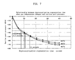
- This characteristic graph suggests an optimum point where only the first vacuum pump acts and excess gas for the second vacuum pump is discharged to the outside from the connection line through the on-off valve of the bypass line, and indicates that the suction port pressure decreases to -42 kPaG, for example, and at the same time, the pressure in the connection line drops to atmospheric pressure, as a result of which the excess gas for the second vacuum pump becomes zero and a minimum and optimum power requirement is provided for the double vacuum pump apparatus with which the first vacuum pump and the second vacuum pump can discharge exhaust gas in a serial manner in cooperation with each other.
- the present inventors found that when the pressure in the connection line between the first vacuum pump and the second vacuum pump becomes equal to the atmospheric pressure, the corresponding pressure at the suction port of the first vacuum pump does not vary with the gas temperature. Specifically, they found that even if the gas temperature has changed and hence the gas adsorption amount has changed, for example, when the pressure at the suction port is -42 kPaG, the pressure in the connection line is atmospheric pressure and does not change with the gas temperature.
- the bent point of the power requirement moves in the direction of -42 kPaG or less when the discharge amount of the first vacuum pump is increased in a combination of the first vacuum pump and the second vacuum pump, and moves in the direction of -42 kPaG or more when the discharge amount of the second vacuum pump is increased.
- the amount of gas adsorbed to the adsorbent decreases during the summer when the gas temperature increases (e.g., at 40°C), and the pressure on the suction port side during the depressurization regeneration decreases and changes as shown in the curve on the lower-side curve in FIG. 7 .
- the on-off valve is configured to be switched from the open state to the closed state when the pressure detector has detected a pressure value indicating that the discharge amount from the discharge port of the first vacuum pump has matched the discharge amount from the second vacuum pump.
- This configuration helps efficiently operating the double vacuum pump apparatus. If the on-off valve is closed before the pressure in the connection line has decreased to the atmospheric pressure, the power requirement of the second vacuum pump increases as shown in FIG. 14 . If the on-off valve is left in the open-state in a state in which the above-described pressure has been reduced to atmospheric pressure or less, the power requirement of the first vacuum pump increases as shown in FIG. 15 .
- each of the first and secondvacuumpumps is a roots pump including a casing and a rotor within the casing, and the rotor of the first vacuum pump and the rotor of the second vacuum pump are configured to be rotationally driven in conjunction with each other by a single motor.
- This configuration is suitable in reducing the power requirement of the present double vacuum pump apparatus.
- the bypass line includes a buffer tube between the first end and the on-off valve tube for suppressing flow vibration of gas flowing into the bypass line.
- the buffer tube is configured such that, in the case where the on-off valve is in the open state, a minimum residence time within the buffer tube of gas passing therethrough is 0.15 second or more when the discharge amount from the discharge port of the first vacuum pump exceeds the discharge capacity of the second vacuum pump.
- the buffer tube includes a constricted portion for locally narrowing the flow path of gas passing through the interior thereof, and the constricted portion has an opening ratio of 20 to 46%.
- the buffer tube includes a plurality of constricted portions for locally narrowing the flow path of gas passing through the interior thereof, and the plurality of constricted portions include a first constricted portion located most upstream in the flow path and a second constricted portion located most downstream.
- the constricted portion is an orifice plate having an opening, or a baffle plate.
- the constricted portion is an orifice plate having an opening, and a portion of an edge of the opening is flush with an inner wall surface of the buffer tube.
- the buffer tube is configured such that, in the case where the on-off valve is in the open state, a maximum flow velocity within the buffer tube of gas passing therethrough is 6 to 12 m/sec when the amount of gas discharged from the discharge port of the first vacuum pump exceeds the suction capacity of the second vacuum pump.
- the buffer tube includes a first end wall on the first end side in the bypass line, a second end wall on the second end side, and a surrounding wall extending between the first and second end walls.
- the bypass line includes a connecting tube portion connected to the buffer tube at a location of the surrounding wall on the first end wall side for introducing gas to the buffer tube, and the connecting tube portion extends in a direction intersecting with the extending direction of the surrounding wall.
- the buffer tube includes a first end wall on the first end side in the bypass line, a second end wall on the second end side, and a surrounding wall extending between the first and second end walls.
- the bypass line includes a connecting tube portion connected to the buffer tube at the first end wall for introducing gas to the buffer tube, and the connecting tube portion has a bent structure for bending the flow of gas immediately before the gas is introduced into the buffer tube.
- a gas purification system includes an adsorption tower whose interior is filled with an adsorbent for purifying gas using pressure swing adsorption (PSA), and a double vacuum pump apparatus according to the first aspect of the present invention for depressurizing the interior of the adsorption tower.
- PSA pressure swing adsorption
- an exhaust gas vibration suppressing device including: a first vacuum pump of a positive displacement-type including a suction port and a discharge port; a second vacuum pump including a suction port and a discharge port and having a discharge capacity smaller than the discharge capacity of the first vacuum pump; a connection line connecting between the discharge port of the first vacuum pump and the suction port of the second vacuum pump; a bypass line having a first end connected to the connection line and a second end for emitting gas to the outside; and an on-off valve disposed between the first end and the second end of the bypass line.
- a buffer tube for suppressing flow vibration of gas flowing into the bypass line is provided between the first end and the on-off valve.
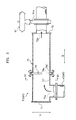
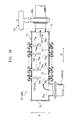
- FIG. 1 shows a schematic configuration of a gas purification system X1 according to an embodiment of the present invention.
- the gas purification system X1 includes a PSA apparatus Y1, a double vacuum pump apparatus Y2, and a silencer Y3.
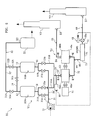
- the PSA apparatus Y1 includes adsorption towers 10A and 10B, a source blower 21, a tank 22, and pipings 31 to 34, and is configured to remove impurities by adsorption from a source gas, which is mixed gas, using pressure swing adsorption (PSA), thereby concentrating and separating a gas component of interest.
- the gas component of interest that is to be purified in this embodiment is oxygen contained in air. In this case, nitrogen is the major impurity.
- Each of the adsorption towers 10A and 10B has gas passage apertures 11 and 12 at opposite ends, and an adsorbent for selectively adsorbing impurities contained in the source gas is filled in the space between the gas passage apertures 11 and 12.
- a zeolite-based adsorbent for selectively adsorbing nitrogen which is the major impurity, is used as the adsorbent.
- molecular sieve carbon it is possible to adsorb oxygen contained in air as the impurity and recover nitrogen as the gas component of interest.
- it is also possible to recover carbon dioxide, carbon monoxide, hydrogen, methane, and the like as the gas component of interest by selecting the combination of the source gas composition and the adsorbent.
- the source blower 21 is an air blower, which is used to supply or feed, to the adsorption towers 10A and 10B, the air that has been sucked as the source gas.
- the tank 22 is used to temporarily store the purified gas (in this embodiment, oxygen).
- the piping 31 includes a main path 31' and branched paths 31A and 31B.
- the main path 31' has an end E1.
- the end E1 is connected to a gas feeding port of the source blower 21.
- the branched paths 31A and 31B are connected to the gas passage apertures 11 side of the adsorption towers 10A and 10B, respectively.
- the branched paths 31A and 31B are provided with automatic valves 31a and 31b that can be switched between the open state and the closed state.
- the piping 32 includes a main path 32' and branched paths 32A and 32B.
- the main path 32' has an end E2.
- the end E2 is connected to the tank 22.
- the branched paths 32A, 32B are connected to the gas passage aperture 12 side of the adsorption towers 10A and 10B, respectively.
- the branched paths 32A, 32B are provided with automatic valves 32a and 32b that can be switched between the open state and the closed state.
- the piping 33 includes a main path 33' and branched paths 33A and 33B.
- the main path 33' has an end E3.
- the end E3 is connected to the double vacuum pump apparatus Y2.
- the branchedpaths 33A and 33B are connected to the gas passage aperture 11 side of the adsorption towers 10A and 10B, respectively.
- the branched paths 33A and 33B are provided with automatic valves 33a and 33b that can be switched between the open state and the closed state.
- a pressure detector 80 is installed in the vicinity of the end E3 of the main path 33', and the pressure detector 80 constantly detects the pressure at a suction port 41 of the vacuum pump 40A.
- the pressure (outlet pressure value) inside the connection line 52 connecting to an discharge port 42 of the vacuum pump 40A is predicted indirectly, and a signal is sent when the inlet pressure value has reached a predetermined threshold (set pressure value) so as to open or close the on-off valve 61.
- the predetermined threshold of the inlet pressure value may be set, for example, to a value at which the above-described outlet pressure value (the pressure inside the connection line 52) becomes equal to atmospheric pressure.
- the piping 34 is provided so as to bridge the branched paths 32A and 32B of the piping 32. Specifically, the piping 34 is connected to the branched path 32A between the automatic valve 32a and the adsorption tower 10A, and is also connected to the branched path 32B between the automatic valve 32b and the adsorption tower 10B. Also, the piping 34 is provided with an automatic valve 34a that can be switched between the open state and the closed state.
- the double vacuum pump apparatus Y2 includes two vacuum pumps 40A and 40B, a motor 51, a connection line 52, a piping 53, and a bypass line 60, and is configured to be able to depressurize the interior of the adsorption towers 10A and 10B of the above-described PSA apparatus Y1 by operation of the vacuum pumps 40A and 40B.
- the vacuum pump 40A is a positive displacement vacuum pump, which is a roots pump in this embodiment.
- the vacuum pump 40B is also a roots pump in this embodiment.
- the discharge capacity (which refers to the maximum amount of gas that can be discharged per unit time, the same as "suction capacity") of the vacuum pump 40B is smaller than that of the vacuum pump 40A.
- the vacuum pumps 40A and 40B each have a suction port 41 and a discharge port 42.
- the end E3 of the piping 33 in the above-described PSA apparatus Y1 is connected to the suction port 41 of the vacuum pump 40A.
- the roots pump includes, for example, as shown in FIG. 2 , a casing 40a, and two rotors 40b having, for example, a cocoon shape, within the casing 40a.
- the two rotors 40b are configured to synchronously rotate in directions opposite to each other.
- the gas that has entered the casing 40a from the suction port 41 is trapped in the space between the casing 40a and the rotor 40b, and is discharged to the discharge port 42 side by rotation of the rotors 40b.
- sealing water supply means (not shown) for supplying the so-called sealing water into the respective casings 40a of the vacuum pumps 40A and 40B is provided in the double vacuum pump apparatus Y2. With the sealing water, it is possible to achieve high air-tightness for the space formed between the casing 40a and the rotor 40b.
- the motor 51 is used to operate the vacuum pumps 40A and 40B.
- the double vacuum pump apparatus Y2 is conf igured such that the rotor of the vacuum pump 40A and the rotor of the vacuum pump 40B are rotationally driven in conjunction with each other by a single motor 51.
- a mechanical interlock is provided between the motor 51 and the vacuum pumps 40A and 40B via shaft components, gear components, and the like such that the rotor of the vacuum pump 40A and the rotor of the vacuum pump 40B are rotated in conjunction with each other by the single motor 51.
- connection line 52 connects between the discharge port 42 of the vacuum pump 40A and the suction port 41 of the vacuum pump 40B.
- the piping 53 has ends E4 and E5. The end E4 of the piping 53 is connected to the discharge port 42 of the vacuum pump 40B. The other end E5 of the piping 53 is connected to the silencer Y3.
- the bypass line 60 has an end E6 serving as the line inlet and an end E7 serving as the line outlet, and has an on-off valve 61 and a buffer tube Z1 within the line.
- the end E6 is connected to the connection line 52 between the vacuum pumps 40A and 40B.
- the end E7 is connected to the piping 53.
- the on-off valve 61 is located between the buffer tube Z1 and the end E5 in the bypass line 60, and, in this embodiment, is open/closed when a pressure set value of the pressure detector 80 is reached.
- the on-off valve 61 is in the open state to allow passage of gas through the bypass line 60.
- the on-off valve 61 is configured to detect the pressure at the suction port 41 (the pressure is specified by a preliminarily conducted test) when the discharge amount (the amount of the gas actually discharged per unit time) from the discharge port 42 of the vacuum pump 40A gradually decreases to match the discharge capacity of the vacuum pump 40B, and to be switched from the open state to the closed state. This control is necessary because the vacuum pump 40B is designed to have a smaller discharge capacity than that of the vacuum pump 40A as described above.
- the buffer tube Z1 constitutes a part of the bypass line 60, and includes an end wall 71 on the end E6 side of the bypass line 60, an the end wall 72 on the end E7 side, a surrounding wall 73 extending between the end walls 71 and 72, and orifice plate 74.
- the surrounding wall 73 has a cylindrical shape.
- a gas inlet 73a is provided at a location of the surrounding wall 73 on the end wall 71 side, and a gas outlet 72a is provided in the end wall 72.
- the surrounding wall 73 extends in the horizontal direction H.
- the length of the surrounding wall 73 (i.e., the buffer tube Z1) in the extending direction is 1 m or more, for example.
- the bypass line 60 includes a connecting tube portion 62 connected to the buffer tube Z1 at the gas inlet 73a provided on the surrounding wall 73.
- the connecting tube portion 62 constitutes a part of the bypass line 60 immediately upstream from the buffer tube Z1 and defines a flow path of gas immediately before the gas is introduced into the buffer tube Z1.
- the connecting tube portion 62 extends in a direction intersecting with the extending direction of the surrounding wall 73 (the horizontal direction H).
- the connecting tube portion 62 extends in a direction orthogonal to the extending direction of the surrounding wall 73. More preferably, the connecting tube portion 62 extends in the direction V and is connected to the surrounding wall 73 of the buffer tube Z1 from below in the vertical direction V.
- the orifice plate 74 is a constricted portion for locally narrowing the flow path of the gas passing through the interior of the buffer tube Z1, and has an opening 74a as shown in FIGS. 3 and 4 .
- the opening ratio of the orifice plate 74 (constricted portion) is preferably 20 to 46%, more preferably 29 to 39%.
- the opening 74a has an edge 74a' that is flush with an inner surface 73' of the surrounding wall 73 of the buffer tube Z1. That is, the rotationally symmetrical axis of the cylindrical buffer tube Z1 and the center of the opening 74a are shifted in position, and the inner surface 73' of the surrounding wall 73 is flush with a distal end 74a' of the edge of the opening 74a.
- the buffer tube Z1 is configured such that in the case where the on-off valve 61 of the bypass line 60 is in the open state, the minimum residence time in the buffer tube of the gas passing through the buffer tube Z1 is 0.15 second or more when the discharge amount from the discharge port 42 of the vacuum pump 40A exceeds the discharge capacity (the same as the suction capacity) of the vacuum pump 40B. As described above, this state occurs because the discharge capacity of the vacuum pump 40B is smaller than that of the vacuum pump 40A.
- the buffer tube Z1 is also configured such that in the case where the on-off valve 61 of the bypass line 60 is in the open state during the operation of the double vacuum pump apparatus Y2, the maximum flow velocity within the buffer tube of the gas passing through the buffer tube Z1 is 6 to 12 m/sec when the discharge amount from the discharge port 42 of the vacuum pump 40A exceeds the discharge capacity of the vacuum pump 40B.
- the silencer Y3 is a device for reducing the noise emitted during the discharge of gas discharged from the gas purification system X1. Therefore, if the noise is not a problem, the silencer Y3 may be omitted and the piping 53 and the bypass line 60 may be directly open to the atmosphere. Furthermore, although , in the embodiment shown in FIG. 1 , the bypass line 60 is merged with the piping 53 and connected to the same silencer Y3, the piping 53 and the bypass line 60 may be connected to separate silencers Y3 and Y3', respectively, as shown in FIG. 5 .
- the gas purification system X1 including the PSA apparatus Y1 and the double vacuum pump apparatus Y2 having the above-described configuration, it is possible to purify a target gas (in this embodiment, oxygen) from a source gas (in this embodiment, air).
- a target gas in this embodiment, oxygen
- a source gas in this embodiment, air
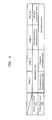
- Steps 1 to 4 an adsorption step, a depressurization regeneration step, and a pressure restoration step are performed in each of the adsorption towers 10A and 10B as shown in FIG. 6 .
- Step 1 the adsorption step is performed in the adsorption tower 10A, and the depressurization regeneration step is performed in the adsorption tower 10B.
- the interior of the adsorption tower 10A, in which the adsorption step is performed in Step 1, is in the state of a relatively high pressure (e.g. , about 40 kPaG, which is slightly higher than atmospheric pressure: G represents the gauge pressure; the same applies in the following) after undergoing Step 4 (the pressure restoration step is performed in the adsorption tower 10A), which will be described below.
- a relatively high pressure e.g. , about 40 kPaG, which is slightly higher than atmospheric pressure: G represents the gauge pressure; the same applies in the following
- Step 1 air is continuously introduced into the gas passage apertures 11 side of the adsorption tower 10A from the source blower 21 via the main path 31' and the branched path 31A of the piping 31, and mainly nitrogen contained in the air is adsorbed by the adsorbent in the adsorption tower 10A, and an oxygen-enriched purified oxygen gas is continuously emitted from the gas passage aperture 12 side of the adsorption tower 10A.
- the purified oxygen gas is guided through the branched path 32A and the main path 32' of the piping 32 to the tank 22, and stored in the tank 22. This purified oxygen gas may be continuously supplied from the tank 22 to a predetermined apparatus or plant.
- Step 1 the interior of the adsorption tower 10B that has undergone Steps 3 to 4 (the adsorption step is performed in the adsorption tower 10B), which will be described below, is depressurized by the double vacuum pump apparatus Y2.
- the gas passage aperture 11 side of the adsorption tower 10B and the suction port 41 side of the vacuum pump 40A of the double vacuum pump apparatus Y2 are in a state of communication via the piping 33, and then the interior of the adsorption tower 10B is depressurized by the double vacuum pump apparatus Y2.
- the double vacuum pump apparatus Y2 Thereby, mainly nitrogen is desorbed from the adsorbent in the adsorption tower 10B and is emitted to the outside of the tower.
- the nitrogen (off gas) is guided to the double vacuum pump apparatus Y2 from the gas passage aperture 11 side of the adsorption tower 10B via the branched path 33B and the main path 33' in the piping 33.
- the internal pressure of the adsorption tower 10B at the start of this depressurization regeneration step is about 40 kPaG, for example.
- the internal pressure of the adsorption tower 10B that is finally reached at the end of the depressurization regeneration step varies depending on the gas temperature, and may be, for example, -66 to -72 kPaG.
- Step 2 the adsorption step is performed in the adsorption tower 10A continuously from Step 1, and the pressure restoration step is performed in the adsorption tower 10B.
- Step 2 specifically, continuously from Step 1, air is continuously supplied to the gas passage aperture 11 side of the adsorption tower 10A from the source blower 21, and the purified oxygen gas is continuously emitted from the gas passage aperture 12 side of the adsorption tower 10A. Apart of the purified oxygen gas is introduced and stored in the tank 22. Another part of the purified gas is guided via the piping 34 to the gas passage aperture 12 side of the adsorption tower 10B.
- Step 2 the purified oxygen gas is introduced from the gas passage aperture 12 side of the adsorption tower 10B side, and thereby, the internal pressure of the adsorption tower 10B is restored. That is, the interior of the adsorption tower 10B is returned to the state of a relatively high pressure (e.g., a pressure ranging from atmospheric pressure to about 40kPaG).
- a relatively high pressure e.g., a pressure ranging from atmospheric pressure to about 40kPaG.
- Steps 3 to 4 the adsorption step is performed in the adsorption tower 10B in the same manner as in the adsorption tower 10A in Steps 1 to 2. Accordingly, in Steps 1 to 2, the purified oxygen gas is continuously emitted from the gas passage aperture 12 side of the adsorption tower 10B, and the purified oxygen gas is introduced and stored in the tank 22. Along with this, in Steps 3 to 4, the depressurization regeneration step (Step 3) and the pressure restoration step (step 4) are performed in the adsorption tower 10A in the same manner as in the adsorption tower 10B in Steps 1 to 2.
- the gas passage aperture 11 side of the adsorption tower 10A and the suction port 41 side of the vacuum pump 40A of the double vacuum pump apparatus Y2 are in a state of communication via the piping 33, and then the interior of the adsorption tower 10A is depressurized by the double vacuum pump apparatus Y2.
- the nitrogen (off gas) is guided to the double vacuum pump apparatus Y2 from the gas passage aperture 11 side of the adsorption tower 10A via the branched path 33A and the main path 33' in the piping 33.
- the adsorbent is regenerated.
- the purified oxygen gas can be continuously obtained from the gas purification system X1, using the air as the source material.
- the double vacuum pump apparatus Y2 is operated in the gas purification system X1 specifically in the following manner.
- Step 1 the depressurization regeneration step is performed in the adsorption tower 10B
- the gas passage aperture 11 side of the adsorption tower 10B of the PSA apparatus Y1 and the suction port 41 side of the vacuum pump 40A of the double vacuum pump apparatus Y2 are in a state of communication via the piping 33, and the vacuum pumps 40A and 40B (which are connected in series via the connection line 52, is driven by the motor 51), and thereby, the interior of the adsorption tower 10B is depressurized.
- the on-off valve 61 of the bypass line 60 in the double vacuum pump apparatus Y2 is open.
- Step 1 the depressurization regeneration step
- the internal pressure of the piping 33 in the vicinity of the suction port 41 is slightly higher than the atmospheric pressure (because the absorption pressure in the adsorption tower B is, for example, 40 kPaG), and the interior of the connection line 52 (the side that is subjected to pressurization by the vacuum pump 40A) is also at a pressure greater than the atmospheric pressure.
- the off gas from the adsorption tower 10B passes through the vacuum pump 40A in the double vacuum pump apparatus Y2, and then a portion thereof passes through the vacuum pump 40B, whereas as a portion thereof passes through the bypass line 60 and is discharged to the outside through the silencer Y3.
- the discharge amount from the vacuum pump 40A that continues to suck the off gas from the adsorption tower 10B undergoing Step 1 changes according to the pressure on the suction port 41 side of the vacuum pump 40A connected to the adsorption tower 10B (i.e., the inlet pressure of the double vacuum pump apparatus Y2). Specifically, the internal pressure of the adsorption tower 10B decreases (hence, the pressure on the suction port 41 side of the vacuum pump 40A also decreases) as the depressurization regeneration step proceeds, and the discharge amount of the vacuum pump 40A decreases accordingly.
- Step 1 Of this discharge amount from the vacuum pump 40A that continues to suck the off gas from the adsorption tower 10B undergoing Step 1, a flow rate of gas exceeding the discharge amount from the vacuum pump 40B is excess gas for the vacuum pump 40B (as described above, the discharge capacity of the vacuum pump 40B is smaller than that of the vacuum pump 40A).
- the excess gas for the vacuum pump 40B is present for a certain period from the start of the depressurization regeneration step (Step 1) for the adsorption tower 10B.
- the discharge amount from the vacuum pump 40A decreases accordingly until it matches the discharge capacity (the same as the suction capacity) of the vacuum pump 40B. After this matching is achieved, the on-off valve 61 turns into the closed state, and therefore, the discharge amount from the vacuum pump 40B continues to decrease while it remains matching the discharge amount from the vacuum pump 40B.
- the change in pressure on the suction port 41 side of the vacuum pump 40A in the depressurization regeneration step according to the gas temperature is as shown in FIG. 7 .
- the pressure at the suction port 41 (the inlet of the double vacuum pump apparatus Y2) of the first vacuum pump 40A quickly drops in the depressurization regeneration time, and the pressure drop becomes slow when the gas temperature becomes low because the gas adsorption amount of the adsorbent increases.
- the point at which the pressure in the connection line 52 between the first vacuum pump 40A and the second vacuum pump 40B becomes equal to atmospheric pressure is in the vicinity of a point at which the pressure at the suction port 41 is about -42 kPaG, and this point will not change even if the gas adsorption amount of the adsorbent has changed as a result of a change in the temperature of the exhaust gas.
- the pressure detector 80 in the vicinity of the suction port 41 side on which no flow vibration occurs and previously setting the inlet pressure value (e.g., -42 kPaG) at a changing point at which the pressure inside the connection line 52 between the first vacuum pump 40A and the second vacuum pump 40B becomes equal to or greater than atmospheric pressure or becomes equal to or less than atmospheric pressure, it is possible to always operate the first vacuum pump 40A and the second vacuum pump 40B in an economical combination, thus operating the double vacuum pump apparatus Y2 with a minimum power requirement.
- the inlet pressure value e.g., -42 kPaG
- the double vacuum pump apparatus Y2 In the double vacuum pump apparatus Y2, during the period starting from the start of the depressurization regeneration step for the adsorption tower 10B and in which the excess gas is present from (i.e. , when the discharge amount from the vacuum pump 40A exceeds the discharge capacity of the vacuum pump 40B), it is detected that the pressure on the suction port 41 side is higher than a pressure set value (e.g., -42 kPaG) of the pressure detector 80, and the on-off valve 61 of the bypass line 60 is turned to the open state, thereby controlling the gas flow so as to cause the excess gas to flow into the bypass line 60 from the connection line 52.
- a pressure set value e.g., -42 kPaG
- the excess gas flows into the bypass line 60 from the connection line 52, thenpasses through the buffer tube Z1 in the bypass line 60, subsequently through the on-off valve 61, is then introduced into the silencer Y3 (or a separate silencer Y3' shown in FIG. 5 ) via the ends E7 and E5, and thereby, the excess gas is discharged via the silencer Y3 to the outside of the gas purification system X1.
- the gas is also discharged from the discharge port 42 of the vacuum pump 40B connected to the vacuum pump 40A via the connection line 52.
- the substantive depressurization work is performed only in the upstream vacuum pump 40A, and the downstream vacuum pump 40B is substantially not involved in the depressurization. Since the discharge port 42 of the vacuum pump 40B is connected to the silencer Y3 via the piping 53, the gas that has passed through the vacuum pump 40B is discharged via the silencer Y3 to the outside of the gas purification system X1.
- the vacuum pumps 40A and 40B that are in a completely serial state depressurize, in cooperation with each other, the interior of the adsorption tower 10B, which is the container to be depressurized, and thereby, a predetermined amount of gas is discharged from the vacuum pump 40B.
- This discharged gas is introduced via the piping 53 into the silencer Y3, and discharged to the outside of the gas purification system X1.
- the on-off valve 61 of the bypass line 60 is in the closed state, and therefore, no gas passes through the bypass line 60.
- the depressurization regeneration step for the adsorption tower 10B in Step 1 described above is performed by operating the double vacuum pump apparatus Y2 so as to perform depressurization in the above-described manner.
- the depressurization regeneration step for the adsorption tower 10A in Step 3 described above is performed by operating the double vacuum pump apparatus Y2 so as to perform depressurization in the same manner described with respect to the depressurization regeneration step for the adsorption tower 10B.
- the on-off valve 61 that is in the open state at the start of depressurization is switched from the open state to the closed state as a result of detection of the pressure on the suction port 41 side by the pressure detector 80 when the discharge amount from the vacuum pump 40A gradually decreases to match the discharge capacity of the vacuum pump 40B.
- This configuration helps serially operating the vacuum pump 40A and the vacuum pump 40B in the latter part of the depressurization regeneration step, thus efficiently operating the double vacuum pump apparatus Y2.
- the set value of the pressure detector 80 that can minimize the power requirement of the double vacuum pump apparatus Y2 is hardly affected by the temperature change, and therefore, there is no problem of increase in the power requirement due to the temperature change, in contrast to the case where the open/close control for the on-off valve 61 is performed by previously setting the time elapsed after the start of the depressurization.
- the double vacuum pump apparatus Y2 is configured such that the rotor 40b of the vacuum pump 40A and the rotor 40b of the vacuum pump 40B are rotationally driven in conjunction with each other by a single motor 51. This configuration is preferable for reducing the power requirement of the double vacuum pump apparatus Y2.
- the discharge amount from the vacuum pump 40A changes according to the pressure at the suction port 41 side of the vacuum pump 40A connected to the adsorption tower 10A or the adsorption tower 10B, and the lower the pressure on the suction port 41, the smaller the amount of the gas exhaust.
- the discharge amount reaches its maximum value at the start of the depressurization regeneration step, and the amount of excess gas reaches its maximum value (flow rate) also at the start of the depressurization in a state in which excess gas (the portion of the discharge amount from the vacuum pump 40A that exceeds the discharge capacity of the vacuum pump 40B) is generated (the on-off valve 61 of the bypass line 60 is in the open state when excess gas is generated). Further, the velocity at which the excess gas flows into the bypass line 60 from the connection line 52 reaches its maximum also at the start of the depressurization.
- the time during which the excess gas passing through the buffer tube Z1 in the bypass line 60 resides in the buffer tube Z1 is the shortest when the excess gas passes through the buffer tube Z1 at the start of the depressurization at which the velocity of flowing into the bypass line 60 from the connection line 52 reaches its maximum.
- the time required for the excess gas to pass through the buffer tube Z1 at the start of the depressurization is referred to as a "minimum residence time within the buffer tube".
- the buffer tube Z1 is configured such that the minimum residence time within the buffer tube is 0.15 second or more.
- Relatively large flow vibration occurs in the gas discharged from the vacuum pump 40A during the depressurizing operation.
- relatively large flow vibration occurs also in the excess gas flowing into the bypass line 60 from the connection line 52.
- the mechanical degradation of a shaft 61a of the on-off valve 61 of the bypass line 60 is facilitated due to the flow vibration of such excess gas. The reason for this is that the shaft 61a that is continuously exposed to the gas flowing through the inside of the bypass line 60 while causing flow vibration is continuously provided with vibration energy by that gas and thus continuously vibrates in an improper manner.
- This vibration of the shaft 61a induces a local destruction of material structure constituting the shaft 61a, and hence promotes degradation of the mechanical strength of the shaft 61a.
- the degradation of the mechanical strength of the shaft 61a becomes particularly noticeable in the case of supplying sealing water into the pump mechanism of the vacuum pump 40A while operating the relevant pump apparatus.
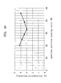
- the level of vibration of the shaft 61a resulting from the flow vibration of the excess gas may reach a vibration acceleration of about 13 G or more.
- the bypass line 60 is provided with the buffer tube Z1, which is configured such that the minimum residence time within the buffer tube is 0.15 second or more, and thereby, the flow vibration of the excess gas is efficiently attenuated in the buffer tube Z1 when the excess gas passes through the bypass line 60. Accordingly, in the double vacuum pump apparatus Y2, the degradation of the mechanical strength of the members located downstream of the buffer tube Z1 (in particular, the shaft 61a of the on-off valve 61) can be sufficiently suppressed.
- the bypass line 60 may include an on-off valve 61' having a check valve function, in place of the on-off valve 61.
- the on-off valve 61' is configured to assume the open state when the pressure on the buffer tube Z1 side of the on-off valve 61' is higher than the pressure on the end E7 side thereof in the bypass line 60 and to assume the closed state when the pressure on the buffer tube Z1 side becomes equal to or less than the pressure on the side of the end E7.
- the on-off valve 61' having this check valve function is in the open state immediately after the start of depressurization, and is automatically switched from the open state to the closed state when the discharge amount from the vacuum pump 40A gradually decreases to match the discharge capacity of the vacuum pump 40B (the pressure inside the connection line 52 at that time is approximately atmospheric pressure).
- This configuration helps reducing the operating loss of the vacuum pump 40B, thus efficiently operating the double vacuum pump apparatus Y2.
- the buffer tube Z1 includes the orifice plate 74 as the constricted portion for locally narrowing the flow path of the gas passing through the interior thereof, and the opening ratio of the orifice plate 74 is preferably 20 to 46%, more preferably 29 to 39%. This configuration is useful for efficiently attenuating the above-described flow vibration of the excess gas passing through the buffer tube Z1. Furthermore, the orifice plate 74 is preferable for accurately adjusting its opening ratio as the constricted portion.
- the distal end 74a' of the edge of the opening 74a is flush with the inner wall surface 73' of the buffer tube Z1. This configuration facilitate the passage through the buffer tube Z1 of water droplets (resulting from the above-described sealing water) contained in the excess gas passing though the buffer tube Z1.
- the buffer tube Z1 may be configured such that the above-described minimum residence time within the buffer tube is 0.15 second or more by appropriately setting the length and/or inside diameter of the buffer tube Z1, without providing the orifice plate 74.
- the buffer tube Z1 is configured such that the maximum flow velocity within the buffer tube of the gas passing through the buffer tube Z1 is 6 to 12 m/sec when the discharge amount from the discharge port 42 of the vacuum pump 40A exceeds the discharge capacity (suction capacity) of the vacuum pump 40B in the case where the on-off valve 61 (or 61') of the bypass line 60 is in the open state during the depressurizing operation of the double vacuum pump apparatus Y2.
- the flow velocity at which the excess gas passes through the buffer tube Z1 in the bypass line 60 is maximum at the start of depressurization, where the velocityof flowing into the bypass line 60 from the connection line 52 is maximum.
- the flow velocity at which the excess gas passes through the buffer tube Z1 at the start of depressurization is referred to as a "maximum flow velocity within the buffer tube".
- the buffer tube Z1 In order to efficiently emit the excess gas from the end E7 of the bypass line 60 while achieving a value of 0.15 second or more for the above-described minimum residence time within the buffer tube, it is preferable to configure the buffer tube Z1 such that the maximum flow velocity within the buffer tube is 6 to 12 m/sec.
- the bypass line 60 includes the connecting tube portion 62, which is connected to the buffer tube Z1 at the gas inlet 73a provided at a location on the end wall 71 side of the surrounding wall 73 in the buffer tube Z1, for introducing gas into the buffer tube Z1.
- the connecting tube portion 62 preferably extends in a direction intersecting with the extending direction (horizontal direction H in FIG. 3 ) of the surrounding wall 73, preferably extends in a direction orthogonal (vertical direction V) thereto, or more preferably, it extends in the vertical direction V and is connected to the surrounding wall 73 from below in the vertical direction V.
- This configuration is suitable for realizing a size reduction for the buffer tube Z1 while achieving a value of 0.15 second or more for the above-described minimum residence time within the buffer tube.
- FIG. 10 is a schematic partial cross-sectional view of a buffer tube Z1' as a first modification and the vicinity thereof.
- the buffer tube Z1' includes an end wall 71 on the end E6 side in the bypass line 60, an end wall 72 on the end E7 side, a surrounding wall 73 extending between the end walls 71 and 72, and a plurality of orifice plates 74, and the end wall 71 is cylindrical.
- Each of the orifice plates 74 is a constricted portion for locally narrowing the flow path of the gas passing through the interior of the buffer tube Z1', and has an opening 74a.
- the plurality of orifice plates 74 are aligned along the gas flow path inside the buffer tube Z1', and include an orifice plate 74' located most upstream in the gas flow path and an orifice plate 74" located most downstream.
- the buffer tube Z1' having this configuration attenuates the flow vibration of the excess gas by the plurality of orifice plates 74 in a step-wise manner, and thus can increase the effect of attenuating flow vibration.
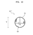
- FIGS. 11 and 12 show a buffer tube Z1" as a second modification.
- the buffer tube Z1" includes an end wall 71 on the end E6 side in the bypass line 60, an end wall 72 on the end E7 side, a surrounding wall 73 extending between the end walls 71 and 72, and a baffle plate 75, and the surrounding wall 73 is cylindrical.
- the baffle plate 75 is a constricted portion for locally narrowing the flow path of the gas passing through the interior of the buffer tube Z1".
- the opening ratio of the baffle plate 75 is preferably 20 to 46%, more preferably 29 to 39%.
- the opening ratio of the baffle plate 75 refers to the ratio of the cross-sectional area of the gas flow path that is not occupied by the baffle plate 75 to the cross-sectional area of the buffer tube Z1".
- the buffer tube Z1" having this configuration functions as the constricted portion of the baffle plate 75, and efficiently attenuates the flow vibration of the excess gas. Furthermore, the opening ratio of the baffle plate 75 can be more easily adjusted than that of an orifice plate.
- the buffer tube Z1" may include a plurality of baffle plates 75.
- the plurality of baffle plates 75 are arranged along the gas flow path at appropriate intervals, and include a first baffle plate located most upstream in the gas flow path and a second baffle plate located most down stream.
- the buffer tube having this configuration attenuates the flow vibration of the excess gas by the plurality of baffle plates 75 in a step-wise manner, and thus can increase the effect of attenuating flow vibration.
- FIGS. 13 and 14 show a buffer tube Z2 as a third modification.
- the buffer tube Z2 includes an end wall 71 on the end E6 side of the bypass line 60', an end wall 72 on the end E7 side, a surrounding wall 73 extending between the end walls 71 and 72, and an orifice plate 74, and the surrounding wall 73 is cylindrical.
- the end wall 71 is provided with a gas inlet 71a and the end wall 72 is provided with a gas outlet 72a.
- the buffer tube Z2 is different from the buffer tube Z1 shown in FIG. 3 in that the gas inlet is provided in the end wall 71 instead of in the surrounding wall 73, but the rest of the configuration is the same as that of the buffer tube Z1 shown in FIG. 3 .
- the connecting tube portion 62' of the bypass line 60' is connected to the buffer tube Z2 at the gas inlet 71a provided in the end wall 71.
- the connecting tube portion 62' is located immediately upstream of the buffer tube Z2 in the bypass line 60', and defines the flow path for the gas immediately before it is introduced into the buffer tube Z2.
- the connecting tube portion 62' has a bent structure for bending the flow of the gas immediately before it is introduced into the buffer tube Z2.
- the connecting tube portion 62' has a bent structure for bending the f low of the gas immediately before it is introduced into the buffer tube Z2 at 90 degrees. More preferably, the connecting tube portion 62' is arranged so as to guide the gas from below in the vertical direction V into the buffer tube Z2.
- the buffer tube Z2 shown in FIG. 13 may be combined with the on-off valve 61' having the check valve function shown in FIG. 9 .
- a plurality of orifice plates 74 may be provided as shown in FIG. 10 , or a single baffle plate 75 (or a plurality of baffle plates 75) shown in FIG. 11 maybe provided.
- the orifice plate 74 shown in FIG. 3 may be combined with the baffle plate 75 shown in FIG. 11 .
- Steps 1 to 4 a cycle including the adsorption step, the depressurization regeneration step, and the pressure restoration step shown in FIG. 6 was repeated in each of the adsorption towers 10A and 10B when the gas temperature was 30°C, using the gas purification system X1 shown in FIG. 1 , and thereby, oxygen was obtained from air serving as a source gas.
- the amount of air supplied by the source blower 21 of the PSA apparatus Y1 was 8,300 N m 3 /h ("N" indicates normal conditions; the same also applies to the following).
- the internal pressure of the adsorption towers 10A and 10B undergoing the adsorption step was a maximum of 40 kPaG. Further, the internal pressure of the adsorption towers 10A and 10B undergoing the depressurization regeneration step was -69 kPaG at the late stage of the depressurization regeneration step, and the internal pressure of the adsorption towers 10A and 10B undergoing the pressure restoration step was returned to atmospheric pressure.
- the depressurization regeneration step for the adsorption towers 10A and 10B was set such that the on-off valve 61 is switched from the open state to the closed state when the pressure on the suction port 41 side had reached a pressure value of -42 kPaG in the pressure detector 80 as the characteristics shown in FIG. 8 .
- the double vacuum pump apparatus Y2 was operated to perform depressurization in the following manner.
- the gas flow was controlled by sending a signal to the on-off valve 61 of the bypass line 60 to switch the on-off valve 61 to the open state so as to cause the excess gas to flow into the bypass line 60 from the connection line 52.
- the on-off valve 61 was switched from the open state to the closed state so as to bring the two vacuum pumps 40A and 40B in a completely serial state, and thereafter the depressurizing operation of the double vacuum pump apparatus Y2 was continued.
- the accumulated average power requirement of the vacuum pumps was 206 kw.
- Steps 1 to 4 a cycle including the adsorption step, the depressurization regeneration step, and the pressure restoration step shown in FIG. 6 was repeated in each of the adsorption towers 10A and 10B when the gas temperature was 40°C, using the gas purification system X1 shown in FIG. 1 , and thereby, oxygen was obtained from air serving as a source gas. Further, the amount of air supplied by the source blower 21 of the PSA apparatus Y1 was 8,300 N m 3 /h.
- the internal pressure of the adsorption towers 10A and 10B undergoing the adsorption step was a maximum of 40 kPaG.
- the internal pressure of the adsorption towers 10A and 10B undergoing the depressurization regeneration step decreased to -72 kPaG at the late stage of the depressurization regeneration step, and the internal pressure of the adsorption towers 10A and 10B undergoing the pressure restoration step was returned to atmospheric pressure.
- the depressurization regeneration step for the adsorption towers 10A and 10B was set such that the on-off valve 61 is switched from the open state to the closed state when the pressure on the suction port 41 side had reached a pressure value of -42 kPaG in the pressure detector 80 as the characteristics shown in FIG. 4 .
- Example 2 The same operation as that in Example 1 was performed for the double vacuum pump apparatus Y2.
- the pressure detector 80 indicated a value of -42 kPaG
- the on-off valve 61 was switched from the open state to the closed state so as to bring the two vacuum pumps 40A and 40B in a completely serial state, and thereafter the depressurizing operation of the double vacuum pump apparatus Y2 was continued.
- the accumulated average power requirement of the vacuum pump was 213 kw.
- Example 1 With the discharge capacity of the first vacuum pump 40A of the double vacuum pump apparatus Y2 set to 14,800 m 3 /h and the discharge capacity of the second vacuum pump 40B set to 14,100 m 3 /h, these pumps were connected in series as roots pumps, and a cycle (Steps 1 to 4) including the adsorption step, the depressurization regeneration step, and the pressure restoration step shown in FIG. 6 was repeated in each of the adsorption towers 10A and 10B when the gas temperature was 30°C, using the gas purification system X1 shown in FIG. 1 , and thereby, oxygen was obtained from air serving as a source gas.
- a cycle (Steps 1 to 4) including the adsorption step, the depressurization regeneration step, and the pressure restoration step shown in FIG. 6 was repeated in each of the adsorption towers 10A and 10B when the gas temperature was 30°C, using the gas purification system X1 shown in FIG. 1 , and thereby, oxygen was obtained from air serving as a
- the amount of air supplied by the source blower 21 of the PSA apparatus Y1 was 8,300 N m 3 /h as in Example 1.
- the internal pressure of the adsorption towers 10A and 10B undergoing the adsorption step was a maximum of 40 kPaG.
- the final pressure in the adsorption towers 10A and 10B undergoing the depressurization regeneration step was -69 kPaG.
- the switching of the on-off valve 61 from the open state to the closed state was performed such that the on-off valve 61 is turned from the open state to the closed state after 7.5 seconds of the depressurization regeneration time as shown in FIG. 7 .
- the pressure at the suction port 41 was indicated as -35 kPaG.
- the internal pressure of the adsorption towers 10A and 10B undergoing the pressure restoration step was returned to atmospheric pressure.
- the double vacuum pump apparatus Y2 was operated to perform depressurization in the following manner. During a period in which the pressure at the suction port 41 changed from approximately atmospheric pressure to -35 kPaG over 7.5 seconds from the start of the depressurization regeneration step, the on-off valve 61 of the bypass line 60 was turned to the open state, then the on-off valve 61 was forcibly switched from the open state to the closed state so as to bring the two vacuum pumps 40A and 40B in a completely serial state, and thereafter the depressurizing operation of the double vacuum pump apparatus Y2 was continued. As a result, the accumulated average power requirement of the vacuum pumps 40A and 40B was 216 kw, which is larger by 10 kw than in the case where the control using the pressure detector 80 on the suction port 41 side was not performed.
- Example 2 With the discharge capacity of the first vacuum pump 40A of the double vacuum pump apparatus Y2 set to 14,800 m 3 /h and the discharge capacity of the second vacuum pump 40B set to 14,100 m 3 /h, these pumps were connected in series as roots pumps, and a cycle (Steps 1 to 4) including the adsorption step, the depressurization regeneration step, and the pressure restoration step shown in FIG. 6 was repeated in each of the adsorption towers 10A and 10B when the gas temperature was 40°C, using the gas purification system X1 shown in FIG. 1 , and thereby, oxygen was obtained from air serving as a source gas.
- a cycle (Steps 1 to 4) including the adsorption step, the depressurization regeneration step, and the pressure restoration step shown in FIG. 6 was repeated in each of the adsorption towers 10A and 10B when the gas temperature was 40°C, using the gas purification system X1 shown in FIG. 1 , and thereby, oxygen was obtained from air serving as a
- the amount of air supplied by the source blower 21 of the PSA apparatus Y1 was 8,300 N m 3 /h as in Example 2.
- the internal pressure of the adsorption towers 10A and 10B undergoing the adsorption step was a maximum of 40 kPaG.
- the final pressure in the adsorption towers 10A and 10B undergoing the depressurization regeneration step was -72 kPaG.
- the switching of the on-off valve 61 from the open state to the closed state was performed such that the on-off valve 61 is switched from the open state to the closed state after 15 seconds of the depressurization regeneration time as shown in FIG. 8 .
- the pressure at the suction port 41 was indicated as -50 kPaG.
- the internal pressure of the adsorption towers 10A and 10B undergoing the pressure restoration step was returned to atmospheric pressure.
- the double vacuum pump apparatus Y2 was operated to perform depressurization in the following manner. During a period in which the pressure at the suction port 41 changed from approximately atmospheric pressure to -50 kPaG over 15 seconds from the start of the depressurization regeneration step, the on-off valve 61 of the bypass line 60 was switched to the open state, then the on-off valve 61 was forcibly switched from the open state to the closed state so as to bring the two vacuum pumps 40A and 40B in a completely serial state, and thereafter the depressurizing operation of the double vacuum pump apparatus Y2 was continued. As a result, the accumulated average power requirement of the vacuum pumps 40A and 40B was 224 kw, which is larger by 11 kw than in the case where the control was not performed using the pressure detector 80 on the suction port 41 side.
- the pressure at the suction port 41 of the upstream vacuum pump 40A a is substantially constant value (-42 kPaG in Examples 1 and 2) at the point when the discharge amount from the upstream vacuum pump 40A in the double vacuum pump apparatus Y2 has decreased to match the discharge capacity from the downstream vacuum pump 40B. Accordingly, the effect of the temperature change can be avoided by measuring the pressure in the vicinity of the suction port 41 of the upstream vacuum pump 40A and controlling the on-off valve 61 so as to open or close.
- a cycle (Steps 1 to 4) including the adsorption step, the depressurization regeneration step, and the pressure restoration step shown in FIG. 6 was repeated in each of the adsorption towers 10A and 10B using a gas purification system X1 having the same configuration as that shown in FIGS. 1 to 4 except that the buffer tube Z1 of the double vacuum pump apparatus Y2 does not have the orifice plate 74, and thereby oxygen was obtained from air serving as source gas.
- the amount of air supplied by the source blower 21 of the PSA apparatus Y1 was set to 4,800 N m 3 /h.
- the internal pressure of the adsorption towers 10A and 10B undergoing the adsorption step was set to atmospheric pressure
- the internal pressure of the adsorption towers 10A and 10B undergoing the depressurization regeneration step at the late stage of the depressurization regeneration step was set to -530 mmHg (gauge pressure: about -70 kPaG)
- the internal pressure of the adsorption towers 10A and 10B undergoing the pressure restoration step was returned to atmospheric pressure.
- the depressurization regeneration step for the adsorption towers 10A and 10B was performed by operating a double vacuum pump apparatus Y2 having the same configuration as that described above except that the buffer tube Z1 does not include the orifice plate 74, so as to perform depressurization.
- a roots pump having a discharge capacity of 10, 000 m 3 /h was used as the vacuum pump 40A.
- a roots pump having a discharge capacity of 6, 053 m 3 /h was used as the vacuum pump 40B.
- a buffer tube having an inner dimension in the extending direction (length) of 4.4 m and an inside diameter of 400 mm was used as the buffer tube Z1 (without the orifice plate 74).
- the double vacuum pump apparatus Y2 was operated to perform depressurization in the following manner. During a predetermined period from the start of the depressurization regeneration step and when excess gas is present (i.e., when the discharge amount from the vacuumpump 40Aexceeds the discharge capacity of the vacuum pump 40B), the on-off valve 61 of the bypass line 60 was turned to the open state, thus controlling the gas flow so as to cause the excess gas to flow into the bypass line 60 from the connection line 52.
- the on-off valve 61 was automatically switched from the open state to the closed state so as to bring the two vacuum pumps 40A and 40B in completely serial state, and then the depressurizing operation for the double vacuum pump apparatus Y2 was continued.
- Example 9 Using the same gas purification system X1 as that in Example 3 except that the length of the buffer tube Z1 (without the orifice plate 74) in the double vacuum pump apparatus Y2 was changed from 4.4 m to 3.6 m (Example 4), 2.8 m (Example 5), 2.1m (Example 6), 1.5 m (Example 7), 1.3 m (Example 8), or 1.05 m (Example 9), a cycle including the adsorption step, the depressurization regeneration step, and the pressure restoration step was repeated for each of the adsorption towers 10A and 10B while operating the double vacuum pump apparatus Y2 to perform depressurization in the depressurization regeneration step, and thereby, oxygen was obtained from air serving as a source gas.
- the minimum residence time within the buffer tube during the depressurizing operation of the double vacuum pump apparatus Y2 was measured for the buffer tube Z1 of the double vacuum pump apparatus Y2 in Examples 4 to 9, and the results were as follows: 0.41 second (Example 4), 0.32 second (Example 5), 0.24 second (Example 6), 0.17 second (Example 7), 0.15 second (Example 8), and 0.12 second (Example 9).
- a cycle (Steps 1 to 4) including the adsorption step, the depressurization regeneration step, and the pressure restoration step shown in FIG. 6 was repeated in each of the adsorption towers 10A and 10B, using a gas purification system X3 as shown in FIG. 17 , and thereby, oxygen was obtained from air serving as a source gas.
- the gas purification system X3 used in Comparative Example 3 has the same configuration as, for example, the gas purification system X1 used in Example 3 except that it is not provided with the buffer tube Z1.
- the depressurization regeneration step for the adsorption towers 10A and 10B was performed by operating the vacuum pumps 40A and 40B to perform pressurization in the same manner as in Example 3 except that gas was not passed through the buffer tube (the on-off valve 61 of the bypass line 60 was switched from the open state to the closed state in the middle of the depressurization regeneration step).
- the maximum value was 13.5 G.
- Example 3 while operating the double vacuum pump apparatus Y2 to perform depressurization in the depressurization regeneration step, a cycle including the adsorption step, the depressurization regeneration step, and the pressure restoration step was repeated in the adsorption towers 10A and 10B, using the same gas purification system X1 as in Example 3 except that the buffer tube Z1 in the double vacuum pump apparatus Y2 included the orifice plate 74, and thereby, oxygen was obtained from air serving as a source gas.
- the orifice plate 74 was provided at a location in the buffer tube Z1 that was 500 mm away from the end wall 71 located on the gas inlet side.
- an orifice plate having an opening 74a with a diameter of 230 mm was used as the orifice plate 74.
- the opening ratio of the orifice plate 74 (the diameter of the opening 74a was 230 mm) in the buffer tube Z1 having an inside diameter of 400 mm was 33%.
- Example 9 As a result of measuring the minimum residence time within the buffer tube during the depressurizing operation of the double vacuum pump apparatus Y2 for the buffer tube Z1 (having the orifice plate 74) of the double vacuum pump apparatus Y2 in Example 10 as in Example 3, it was 0.50 second. Further, as a result of measuring the vibration acceleration applied to the shaft 61a of the on-off valve 61 in the open state during the depressurizing operation of the double vacuum pump apparatus Y2, the maximum value was 2.1 G. These results of measurement for Example 9 are shown in the table in FIG. 16 .
- Example 3 the minimum residence time within the buffer tube during the depressurizing operation of the double vacuum pump apparatus Y2 was measured for the buffer tube Z1 of the double vacuum pump apparatus Y2 in Examples 11 to 16, and the results were as follows: 0.41 second (Example 11), 0.32 second (Example 12), 0.24 second (Example 13), 0.17 second (Example 14), 0.15 second (Example 15), and 0.12 second (Example 16).
- Example 22 Using the same gas purification system X1 as that in Example 10 except that the diameter of the opening 74a of the orifice plate 74 of the buffer tube Z1 in the double vacuum pump apparatus Y2 was changed from 230 mm to 180 mm (Example 17), 200 mm (Example 18), 215 mm (Example 19), 230 mm (Example 20), 250 mm (Example 21), or 270 mm (Example 22), a cycle including the adsorption step, the depressurization regeneration step, and the pressure restoration step was repeated in each of the adsorption towers 10A and 10B, while operating the double vacuum pump apparatus Y2 in the depressurization regeneration step, and thereby, oxygen was obtained from air serving as a source gas.
- the opening ratio of the orifice plate 74 in Example 17 in the buffer tube Z1 having an inside diameter of 400 mm was 20%, the opening ratio of the orifice plate 74 in Example 18 was 25%, the opening ratio of the orifice plate 74 in Example 19 was 29%, the opening ratio of the orifice plate 74 in Example 20 was 33%, the opening ratio of the orifice plate 74 in Example 21 was 39%, and the opening ratio of the orifice plate 74 of Example 22 was 46%.
- Example 3 the minimum residence time within the buffer tube during the depressurizing operation of the double vacuum pump apparatus Y2 was measured for the buffer tube Z1 of the double vacuum pump apparatus Y2 in Examples 17 to 22, and all was 0.15 second.
- the maximum values were as follows: 4.2 G (Example 17), 3.8 G (Example 18), 3.4 G (Example 19), 3.0 G (Example 20), 3.3 G (Example 21), and 4.0 G (Example 22).
- the results of the measurement for Example 17 to 22 are shown in the table in FIG.
- the horizontal axis represents the opening ratio of the orifice plate 74 (constricted portion) (%), and the vertical axis represents the vibration acceleration (G) of the shaft 61a of the on-off valve 61.
- a comparison of Examples 3 to 22 and Comparative Example 3 indicates that the vibration acceleration applied to the shaft 61a of the on-off valve 61 is smaller in the gas purification system X1 (Examples 3 to 22) shown in FIG. 1 , which was with the buffer tube Z1, than in the gas purification system X3 (Comparative Example 3) shown in FIG. 17 , in which this buffer tube was not provided. Further, if the length of the buffer tube is the same, this vibration acceleration of the shaft 61a of the on-off valve 61 is smaller when the orifice plate 74 is provided (Examples 10 to 16), than when such orifice plate is not provided.
- the vibration acceleration applied to the shaft 61a of the on-off valve 61 can be made particularly small.
Priority Applications (1)
| Application Number | Priority Date | Filing Date | Title |
|---|---|---|---|
| EP19156439.2A EP3502472B1 (de) | 2009-12-24 | 2010-12-22 | Abgasvibrationsunterdrückungsvorrichtung in einer doppelvakuumpumpe |
Applications Claiming Priority (3)
| Application Number | Priority Date | Filing Date | Title |
|---|---|---|---|
| JP2009291796A JP4677041B1 (ja) | 2009-12-24 | 2009-12-24 | 二連型真空ポンプ装置、ガス精製システム、真空ポンプ排ガス振動抑制装置、および真空ポンプ排ガス振動抑制方法 |
| JP2010223841A JP4664444B1 (ja) | 2010-10-01 | 2010-10-01 | 二連型真空ポンプ装置、およびそれを備えるガス精製システム、ならびに二連型真空ポンプ装置の制御方法 |
| PCT/JP2010/073091 WO2011078207A1 (ja) | 2009-12-24 | 2010-12-22 | 二連型真空ポンプ装置、およびそれを備えるガス精製システム、 ならびに二連型真空ポンプ装置における排ガス振動抑制装置 |
Related Child Applications (2)
| Application Number | Title | Priority Date | Filing Date |
|---|---|---|---|
| EP19156439.2A Division-Into EP3502472B1 (de) | 2009-12-24 | 2010-12-22 | Abgasvibrationsunterdrückungsvorrichtung in einer doppelvakuumpumpe |
| EP19156439.2A Division EP3502472B1 (de) | 2009-12-24 | 2010-12-22 | Abgasvibrationsunterdrückungsvorrichtung in einer doppelvakuumpumpe |
Publications (3)
| Publication Number | Publication Date |
|---|---|
| EP2518317A1 true EP2518317A1 (de) | 2012-10-31 |
| EP2518317A4 EP2518317A4 (de) | 2017-11-01 |
| EP2518317B1 EP2518317B1 (de) | 2019-06-05 |
Family
ID=44195734
Family Applications (2)
| Application Number | Title | Priority Date | Filing Date |
|---|---|---|---|
| EP19156439.2A Active EP3502472B1 (de) | 2009-12-24 | 2010-12-22 | Abgasvibrationsunterdrückungsvorrichtung in einer doppelvakuumpumpe |
| EP10839437.0A Active EP2518317B1 (de) | 2009-12-24 | 2010-12-22 | Doppelvakuumpumpenvorrichtung, gasreinigungssystem mit der doppelvakuumpumpenvorrichtung und abgasvibrationsunterdrückungsvorrichtung in der doppelvakuumpumpenvorrichtung |
Family Applications Before (1)
| Application Number | Title | Priority Date | Filing Date |
|---|---|---|---|
| EP19156439.2A Active EP3502472B1 (de) | 2009-12-24 | 2010-12-22 | Abgasvibrationsunterdrückungsvorrichtung in einer doppelvakuumpumpe |
Country Status (7)
| Country | Link |
|---|---|
| US (1) | US8715400B2 (de) |
| EP (2) | EP3502472B1 (de) |
| KR (1) | KR101506026B1 (de) |
| BR (1) | BR112012018803B1 (de) |
| ES (2) | ES2818976T3 (de) |
| TW (1) | TWI490411B (de) |
| WO (1) | WO2011078207A1 (de) |
Cited By (1)
| Publication number | Priority date | Publication date | Assignee | Title |
|---|---|---|---|---|
| CN109441775A (zh) * | 2018-11-29 | 2019-03-08 | 东莞市维健维康科技有限公司 | 一种真空系统 |
Families Citing this family (10)
| Publication number | Priority date | Publication date | Assignee | Title |
|---|---|---|---|---|
| CH706231B1 (fr) * | 2012-03-05 | 2016-07-29 | Ateliers Busch Sa | Installation de pompage et procédé de contrôle d'une telle installation. |
| DE102013219464A1 (de) * | 2013-09-26 | 2015-03-26 | Inficon Gmbh | Evakuierung einer Folienkammer |
| WO2016014232A1 (en) * | 2014-07-25 | 2016-01-28 | Exxonmobil Upstream Research Company | Apparatus and system having a valve assembly and swing adsorption processes related thereto |
| DE202017003212U1 (de) * | 2017-06-17 | 2018-09-18 | Leybold Gmbh | Mehrstufige Wälzkolbenpumpe |
| IT201700074132A1 (it) * | 2017-07-03 | 2019-01-03 | Ecospray Tech Srl | Sistema e metodo di filtraggio per gas |
| CN112118900A (zh) * | 2018-09-05 | 2020-12-22 | 系统工程服务有限公司 | 废气处理方法及装置 |
| CN112185788B (zh) * | 2019-07-04 | 2023-09-29 | 中微半导体设备(上海)股份有限公司 | 一种等离子处理装置及其方法 |
| FR3112171B1 (fr) * | 2020-10-16 | 2022-07-08 | Pfeiffer Vacuum | Procédé de contrôle d’une puissance de fonctionnement d’une pompe à vide et pompe à vide |
| CN114939445B (zh) * | 2022-03-29 | 2023-12-22 | 合肥通用机械研究院有限公司 | 一种大型真空度变化试验装置及应用该装置的试验方法 |
| CN117386541B (zh) * | 2023-12-11 | 2024-02-09 | 四川航天世源科技有限公司 | 一种双余度电动燃油泵 |
Family Cites Families (23)
| Publication number | Priority date | Publication date | Assignee | Title |
|---|---|---|---|---|
| US3922110A (en) * | 1974-01-28 | 1975-11-25 | Henry Huse | Multi-stage vacuum pump |
| US4505647A (en) * | 1978-01-26 | 1985-03-19 | Grumman Allied Industries, Inc. | Vacuum pumping system |
| JPS607920A (ja) * | 1983-06-29 | 1985-01-16 | Hitachi Ltd | 非凝縮性混合ガスの分離方法 |
| JPS62241524A (ja) * | 1986-04-14 | 1987-10-22 | Kawasaki Steel Corp | 純度安定化に優れる一酸化炭素の分離精製方法 |
| US4850806A (en) * | 1988-05-24 | 1989-07-25 | The Boc Group, Inc. | Controlled by-pass for a booster pump |
| JPH04326943A (ja) * | 1991-04-25 | 1992-11-16 | Hitachi Ltd | 真空排気システム及び排気方法 |
| DE4213763B4 (de) * | 1992-04-27 | 2004-11-25 | Unaxis Deutschland Holding Gmbh | Verfahren zum Evakuieren einer Vakuumkammer und einer Hochvakuumkammer sowie Hochvakuumanlage zu seiner Durchführung |
| JP3378949B2 (ja) * | 1993-03-09 | 2003-02-17 | 日本酸素株式会社 | 圧力変動式空気分離装置及びその運転方法 |
| DE19500823A1 (de) * | 1995-01-13 | 1996-07-18 | Sgi Prozess Technik Gmbh | Vakuum-Pumpstand |
| JP3309197B2 (ja) * | 1995-03-02 | 2002-07-29 | 住友精化株式会社 | 濃縮酸素の回収方法 |
| DE19524609A1 (de) * | 1995-07-06 | 1997-01-09 | Leybold Ag | Vorrichtung zum raschen Evakuieren einer Vakuumkammer |
| JP3121286B2 (ja) | 1997-04-24 | 2000-12-25 | エア・ウォーター株式会社 | 真空ポンプ排気システム |
| DE19929519A1 (de) * | 1999-06-28 | 2001-01-04 | Pfeiffer Vacuum Gmbh | Verfahren zum Betrieb einer Mehrkammer-Vakuumanlage |
| JP4429450B2 (ja) * | 2000-02-04 | 2010-03-10 | 大陽日酸株式会社 | 圧力変動吸着酸素製造方法及び装置 |
| US20050189074A1 (en) * | 2002-11-08 | 2005-09-01 | Tokyo Electron Limited | Gas processing apparatus and method and computer storage medium storing program for controlling same |
| US6589023B2 (en) * | 2001-10-09 | 2003-07-08 | Applied Materials, Inc. | Device and method for reducing vacuum pump energy consumption |
| JP2003343469A (ja) * | 2002-03-20 | 2003-12-03 | Toyota Industries Corp | 真空ポンプ |
| DE10319633A1 (de) * | 2003-05-02 | 2004-11-18 | Inficon Gmbh | Lecksuchgerät |
| EP1666877B1 (de) * | 2003-09-10 | 2010-09-08 | Astellas Pharma Inc. | Vorrichtung zur verdampfung von lösungsmitteln im vakuum |
| GB0329839D0 (en) * | 2003-12-23 | 2004-01-28 | Boc Group Plc | Vacuum pump |
| JP4685662B2 (ja) | 2005-03-03 | 2011-05-18 | エア・ウォーター株式会社 | ガス分離方法およびそれに用いる装置 |
| GB0505500D0 (en) * | 2005-03-17 | 2005-04-27 | Boc Group Plc | Vacuum pumping arrangement |
| JP5675505B2 (ja) * | 2011-06-07 | 2015-02-25 | 住友精化株式会社 | 目的ガス分離方法、および目的ガス分離装置 |
-
2010
- 2010-12-22 EP EP19156439.2A patent/EP3502472B1/de active Active
- 2010-12-22 ES ES19156439T patent/ES2818976T3/es active Active
- 2010-12-22 ES ES10839437T patent/ES2731202T3/es active Active
- 2010-12-22 US US13/518,257 patent/US8715400B2/en active Active
- 2010-12-22 BR BR112012018803-8A patent/BR112012018803B1/pt active IP Right Grant
- 2010-12-22 WO PCT/JP2010/073091 patent/WO2011078207A1/ja active Application Filing
- 2010-12-22 KR KR1020127019512A patent/KR101506026B1/ko active IP Right Grant
- 2010-12-22 EP EP10839437.0A patent/EP2518317B1/de active Active
- 2010-12-23 TW TW099145461A patent/TWI490411B/zh active
Non-Patent Citations (1)
| Title |
|---|
| See references of WO2011078207A1 * |
Cited By (1)
| Publication number | Priority date | Publication date | Assignee | Title |
|---|---|---|---|---|
| CN109441775A (zh) * | 2018-11-29 | 2019-03-08 | 东莞市维健维康科技有限公司 | 一种真空系统 |
Also Published As
| Publication number | Publication date |
|---|---|
| US20120255445A1 (en) | 2012-10-11 |
| EP2518317B1 (de) | 2019-06-05 |
| EP2518317A4 (de) | 2017-11-01 |
| WO2011078207A1 (ja) | 2011-06-30 |
| EP3502472A1 (de) | 2019-06-26 |
| BR112012018803A2 (pt) | 2020-09-01 |
| TW201139855A (en) | 2011-11-16 |
| ES2818976T3 (es) | 2021-04-14 |
| KR101506026B1 (ko) | 2015-03-25 |
| TWI490411B (zh) | 2015-07-01 |
| EP3502472B1 (de) | 2020-09-09 |
| BR112012018803B1 (pt) | 2021-09-28 |
| KR20120120256A (ko) | 2012-11-01 |
| ES2731202T3 (es) | 2019-11-14 |
| US8715400B2 (en) | 2014-05-06 |
Similar Documents
| Publication | Publication Date | Title |
|---|---|---|
| EP2518317B1 (de) | Doppelvakuumpumpenvorrichtung, gasreinigungssystem mit der doppelvakuumpumpenvorrichtung und abgasvibrationsunterdrückungsvorrichtung in der doppelvakuumpumpenvorrichtung | |
| AU2007298122B2 (en) | Oxygen concentrator | |
| KR101511803B1 (ko) | 산소 농축 장치 | |
| CN106456927B (zh) | 基于氧气输出流速控制氧气浓缩器定时循环 | |
| ES2711552T3 (es) | Control de velocidad anti-sobrecarga de un compresor en un aparato VPSA | |
| KR20120112401A (ko) | 산소 농축 장치 | |
| KR101120992B1 (ko) | 산소 가스 및 질소 가스의 병행 분리방법 및 병행 분리시스템 | |
| JP5581243B2 (ja) | 空気圧縮機 | |
| JP4758129B2 (ja) | 酸素濃縮装置 | |
| JP5027662B2 (ja) | 酸素ガスおよび窒素ガスの併行分離方法および併行分離システム | |
| JP5010772B2 (ja) | 気体分離装置 | |
| JP5015831B2 (ja) | 酸素濃縮器 | |
| JP4664444B1 (ja) | 二連型真空ポンプ装置、およびそれを備えるガス精製システム、ならびに二連型真空ポンプ装置の制御方法 | |
| JP2009082782A (ja) | 気体分離装置 | |
| JP2007054678A (ja) | 気体濃縮における気体濃度の安定化方法及び気体濃縮装置 | |
| JP2006015221A (ja) | 気体分離装置 | |
| JP5022785B2 (ja) | 気体分離装置 | |
| JP4677041B1 (ja) | 二連型真空ポンプ装置、ガス精製システム、真空ポンプ排ガス振動抑制装置、および真空ポンプ排ガス振動抑制方法 | |
| JP3749150B2 (ja) | 濃縮酸素供給装置 | |
| KR100484549B1 (ko) | 두 개의 진공원을 이용한 산소발생장치 및 방법 | |
| JP4594223B2 (ja) | 窒素ガス発生装置 | |
| JP3033038U (ja) | 圧力変動吸着法によるガス供給装置 |
Legal Events
| Date | Code | Title | Description |
|---|---|---|---|
| PUAI | Public reference made under article 153(3) epc to a published international application that has entered the european phase |
Free format text: ORIGINAL CODE: 0009012 |
|
| 17P | Request for examination filed |
Effective date: 20120710 |
|
| AK | Designated contracting states |
Kind code of ref document: A1 Designated state(s): AL AT BE BG CH CY CZ DE DK EE ES FI FR GB GR HR HU IE IS IT LI LT LU LV MC MK MT NL NO PL PT RO RS SE SI SK SM TR |
|
| DAX | Request for extension of the european patent (deleted) | ||
| RA4 | Supplementary search report drawn up and despatched (corrected) |
Effective date: 20171004 |
|
| RIC1 | Information provided on ipc code assigned before grant |
Ipc: B01D 53/04 20060101ALI20170927BHEP Ipc: F04C 25/02 20060101ALI20170927BHEP Ipc: F04B 37/14 20060101AFI20170927BHEP Ipc: F04C 18/12 20060101ALI20170927BHEP Ipc: F04B 49/00 20060101ALI20170927BHEP Ipc: F04B 41/06 20060101ALI20170927BHEP Ipc: F04C 23/00 20060101ALI20170927BHEP Ipc: F04C 28/02 20060101ALI20170927BHEP Ipc: B01D 53/047 20060101ALI20170927BHEP |
|
| STAA | Information on the status of an ep patent application or granted ep patent |
Free format text: STATUS: EXAMINATION IS IN PROGRESS |
|
| 17Q | First examination report despatched |
Effective date: 20180525 |
|
| REG | Reference to a national code |
Ref country code: DE Ref legal event code: R079 Ref document number: 602010059312 Country of ref document: DE Free format text: PREVIOUS MAIN CLASS: F04B0037160000 Ipc: F04B0037140000 |
|
| GRAP | Despatch of communication of intention to grant a patent |
Free format text: ORIGINAL CODE: EPIDOSNIGR1 |
|
| STAA | Information on the status of an ep patent application or granted ep patent |
Free format text: STATUS: GRANT OF PATENT IS INTENDED |
|
| RIC1 | Information provided on ipc code assigned before grant |
Ipc: F04B 37/14 20060101AFI20181130BHEP Ipc: F04B 49/00 20060101ALI20181130BHEP Ipc: F04C 28/02 20060101ALI20181130BHEP Ipc: F04B 41/06 20060101ALI20181130BHEP Ipc: F04C 25/02 20060101ALI20181130BHEP Ipc: F04C 18/12 20060101ALI20181130BHEP Ipc: F04C 23/00 20060101ALI20181130BHEP Ipc: F04C 28/26 20060101ALI20181130BHEP Ipc: B01D 53/047 20060101ALI20181130BHEP Ipc: B01D 53/04 20060101ALI20181130BHEP |
|
| INTG | Intention to grant announced |
Effective date: 20181221 |
|
| GRAS | Grant fee paid |
Free format text: ORIGINAL CODE: EPIDOSNIGR3 |
|
| GRAA | (expected) grant |
Free format text: ORIGINAL CODE: 0009210 |
|
| STAA | Information on the status of an ep patent application or granted ep patent |
Free format text: STATUS: THE PATENT HAS BEEN GRANTED |
|
| AK | Designated contracting states |
Kind code of ref document: B1 Designated state(s): AL AT BE BG CH CY CZ DE DK EE ES FI FR GB GR HR HU IE IS IT LI LT LU LV MC MK MT NL NO PL PT RO RS SE SI SK SM TR |
|
| REG | Reference to a national code |
Ref country code: GB Ref legal event code: FG4D |
|
| REG | Reference to a national code |
Ref country code: CH Ref legal event code: EP |
|
| REG | Reference to a national code |
Ref country code: AT Ref legal event code: REF Ref document number: 1140255 Country of ref document: AT Kind code of ref document: T Effective date: 20190615 |
|
| REG | Reference to a national code |
Ref country code: IE Ref legal event code: FG4D |
|
| REG | Reference to a national code |
Ref country code: DE Ref legal event code: R096 Ref document number: 602010059312 Country of ref document: DE |
|
| REG | Reference to a national code |
Ref country code: DE Ref legal event code: R082 Ref document number: 602010059312 Country of ref document: DE |
|
| REG | Reference to a national code |
Ref country code: NL Ref legal event code: MP Effective date: 20190605 |
|
| REG | Reference to a national code |
Ref country code: LT Ref legal event code: MG4D |
|
| PG25 | Lapsed in a contracting state [announced via postgrant information from national office to epo] |
Ref country code: FI Free format text: LAPSE BECAUSE OF FAILURE TO SUBMIT A TRANSLATION OF THE DESCRIPTION OR TO PAY THE FEE WITHIN THE PRESCRIBED TIME-LIMIT Effective date: 20190605 Ref country code: NO Free format text: LAPSE BECAUSE OF FAILURE TO SUBMIT A TRANSLATION OF THE DESCRIPTION OR TO PAY THE FEE WITHIN THE PRESCRIBED TIME-LIMIT Effective date: 20190905 Ref country code: AL Free format text: LAPSE BECAUSE OF FAILURE TO SUBMIT A TRANSLATION OF THE DESCRIPTION OR TO PAY THE FEE WITHIN THE PRESCRIBED TIME-LIMIT Effective date: 20190605 Ref country code: SE Free format text: LAPSE BECAUSE OF FAILURE TO SUBMIT A TRANSLATION OF THE DESCRIPTION OR TO PAY THE FEE WITHIN THE PRESCRIBED TIME-LIMIT Effective date: 20190605 Ref country code: LT Free format text: LAPSE BECAUSE OF FAILURE TO SUBMIT A TRANSLATION OF THE DESCRIPTION OR TO PAY THE FEE WITHIN THE PRESCRIBED TIME-LIMIT Effective date: 20190605 Ref country code: HR Free format text: LAPSE BECAUSE OF FAILURE TO SUBMIT A TRANSLATION OF THE DESCRIPTION OR TO PAY THE FEE WITHIN THE PRESCRIBED TIME-LIMIT Effective date: 20190605 |
|
| REG | Reference to a national code |
Ref country code: ES Ref legal event code: FG2A Ref document number: 2731202 Country of ref document: ES Kind code of ref document: T3 Effective date: 20191114 |
|
| PG25 | Lapsed in a contracting state [announced via postgrant information from national office to epo] |
Ref country code: LV Free format text: LAPSE BECAUSE OF FAILURE TO SUBMIT A TRANSLATION OF THE DESCRIPTION OR TO PAY THE FEE WITHIN THE PRESCRIBED TIME-LIMIT Effective date: 20190605 Ref country code: RS Free format text: LAPSE BECAUSE OF FAILURE TO SUBMIT A TRANSLATION OF THE DESCRIPTION OR TO PAY THE FEE WITHIN THE PRESCRIBED TIME-LIMIT Effective date: 20190605 Ref country code: BG Free format text: LAPSE BECAUSE OF FAILURE TO SUBMIT A TRANSLATION OF THE DESCRIPTION OR TO PAY THE FEE WITHIN THE PRESCRIBED TIME-LIMIT Effective date: 20190905 Ref country code: GR Free format text: LAPSE BECAUSE OF FAILURE TO SUBMIT A TRANSLATION OF THE DESCRIPTION OR TO PAY THE FEE WITHIN THE PRESCRIBED TIME-LIMIT Effective date: 20190906 |
|
| REG | Reference to a national code |
Ref country code: AT Ref legal event code: MK05 Ref document number: 1140255 Country of ref document: AT Kind code of ref document: T Effective date: 20190605 |
|
| PG25 | Lapsed in a contracting state [announced via postgrant information from national office to epo] |
Ref country code: PT Free format text: LAPSE BECAUSE OF FAILURE TO SUBMIT A TRANSLATION OF THE DESCRIPTION OR TO PAY THE FEE WITHIN THE PRESCRIBED TIME-LIMIT Effective date: 20191007 Ref country code: AT Free format text: LAPSE BECAUSE OF FAILURE TO SUBMIT A TRANSLATION OF THE DESCRIPTION OR TO PAY THE FEE WITHIN THE PRESCRIBED TIME-LIMIT Effective date: 20190605 Ref country code: EE Free format text: LAPSE BECAUSE OF FAILURE TO SUBMIT A TRANSLATION OF THE DESCRIPTION OR TO PAY THE FEE WITHIN THE PRESCRIBED TIME-LIMIT Effective date: 20190605 Ref country code: SK Free format text: LAPSE BECAUSE OF FAILURE TO SUBMIT A TRANSLATION OF THE DESCRIPTION OR TO PAY THE FEE WITHIN THE PRESCRIBED TIME-LIMIT Effective date: 20190605 Ref country code: RO Free format text: LAPSE BECAUSE OF FAILURE TO SUBMIT A TRANSLATION OF THE DESCRIPTION OR TO PAY THE FEE WITHIN THE PRESCRIBED TIME-LIMIT Effective date: 20190605 Ref country code: NL Free format text: LAPSE BECAUSE OF FAILURE TO SUBMIT A TRANSLATION OF THE DESCRIPTION OR TO PAY THE FEE WITHIN THE PRESCRIBED TIME-LIMIT Effective date: 20190605 Ref country code: CZ Free format text: LAPSE BECAUSE OF FAILURE TO SUBMIT A TRANSLATION OF THE DESCRIPTION OR TO PAY THE FEE WITHIN THE PRESCRIBED TIME-LIMIT Effective date: 20190605 |
|
| PG25 | Lapsed in a contracting state [announced via postgrant information from national office to epo] |
Ref country code: SM Free format text: LAPSE BECAUSE OF FAILURE TO SUBMIT A TRANSLATION OF THE DESCRIPTION OR TO PAY THE FEE WITHIN THE PRESCRIBED TIME-LIMIT Effective date: 20190605 Ref country code: IS Free format text: LAPSE BECAUSE OF FAILURE TO SUBMIT A TRANSLATION OF THE DESCRIPTION OR TO PAY THE FEE WITHIN THE PRESCRIBED TIME-LIMIT Effective date: 20191005 |
|
| REG | Reference to a national code |
Ref country code: DE Ref legal event code: R097 Ref document number: 602010059312 Country of ref document: DE |
|
| PG25 | Lapsed in a contracting state [announced via postgrant information from national office to epo] |
Ref country code: TR Free format text: LAPSE BECAUSE OF FAILURE TO SUBMIT A TRANSLATION OF THE DESCRIPTION OR TO PAY THE FEE WITHIN THE PRESCRIBED TIME-LIMIT Effective date: 20190605 |
|
| PLBE | No opposition filed within time limit |
Free format text: ORIGINAL CODE: 0009261 |
|
| STAA | Information on the status of an ep patent application or granted ep patent |
Free format text: STATUS: NO OPPOSITION FILED WITHIN TIME LIMIT |
|
| PG25 | Lapsed in a contracting state [announced via postgrant information from national office to epo] |
Ref country code: DK Free format text: LAPSE BECAUSE OF FAILURE TO SUBMIT A TRANSLATION OF THE DESCRIPTION OR TO PAY THE FEE WITHIN THE PRESCRIBED TIME-LIMIT Effective date: 20190605 Ref country code: PL Free format text: LAPSE BECAUSE OF FAILURE TO SUBMIT A TRANSLATION OF THE DESCRIPTION OR TO PAY THE FEE WITHIN THE PRESCRIBED TIME-LIMIT Effective date: 20190605 |
|
| 26N | No opposition filed |
Effective date: 20200306 |
|
| PG25 | Lapsed in a contracting state [announced via postgrant information from national office to epo] |
Ref country code: SI Free format text: LAPSE BECAUSE OF FAILURE TO SUBMIT A TRANSLATION OF THE DESCRIPTION OR TO PAY THE FEE WITHIN THE PRESCRIBED TIME-LIMIT Effective date: 20190605 |
|
| REG | Reference to a national code |
Ref country code: CH Ref legal event code: PL |
|
| REG | Reference to a national code |
Ref country code: BE Ref legal event code: MM Effective date: 20191231 |
|
| PG25 | Lapsed in a contracting state [announced via postgrant information from national office to epo] |
Ref country code: MC Free format text: LAPSE BECAUSE OF FAILURE TO SUBMIT A TRANSLATION OF THE DESCRIPTION OR TO PAY THE FEE WITHIN THE PRESCRIBED TIME-LIMIT Effective date: 20190605 |
|
| PG25 | Lapsed in a contracting state [announced via postgrant information from national office to epo] |
Ref country code: IE Free format text: LAPSE BECAUSE OF NON-PAYMENT OF DUE FEES Effective date: 20191222 Ref country code: LU Free format text: LAPSE BECAUSE OF NON-PAYMENT OF DUE FEES Effective date: 20191222 |
|
| PG25 | Lapsed in a contracting state [announced via postgrant information from national office to epo] |
Ref country code: CH Free format text: LAPSE BECAUSE OF NON-PAYMENT OF DUE FEES Effective date: 20191231 Ref country code: LI Free format text: LAPSE BECAUSE OF NON-PAYMENT OF DUE FEES Effective date: 20191231 Ref country code: BE Free format text: LAPSE BECAUSE OF NON-PAYMENT OF DUE FEES Effective date: 20191231 |
|
| PG25 | Lapsed in a contracting state [announced via postgrant information from national office to epo] |
Ref country code: CY Free format text: LAPSE BECAUSE OF FAILURE TO SUBMIT A TRANSLATION OF THE DESCRIPTION OR TO PAY THE FEE WITHIN THE PRESCRIBED TIME-LIMIT Effective date: 20190605 |
|
| PG25 | Lapsed in a contracting state [announced via postgrant information from national office to epo] |
Ref country code: MT Free format text: LAPSE BECAUSE OF FAILURE TO SUBMIT A TRANSLATION OF THE DESCRIPTION OR TO PAY THE FEE WITHIN THE PRESCRIBED TIME-LIMIT Effective date: 20190605 Ref country code: HU Free format text: LAPSE BECAUSE OF FAILURE TO SUBMIT A TRANSLATION OF THE DESCRIPTION OR TO PAY THE FEE WITHIN THE PRESCRIBED TIME-LIMIT; INVALID AB INITIO Effective date: 20101222 |
|
| PG25 | Lapsed in a contracting state [announced via postgrant information from national office to epo] |
Ref country code: MK Free format text: LAPSE BECAUSE OF FAILURE TO SUBMIT A TRANSLATION OF THE DESCRIPTION OR TO PAY THE FEE WITHIN THE PRESCRIBED TIME-LIMIT Effective date: 20190605 |
|
| PGFP | Annual fee paid to national office [announced via postgrant information from national office to epo] |
Ref country code: ES Payment date: 20230227 Year of fee payment: 13 |
|
| P01 | Opt-out of the competence of the unified patent court (upc) registered |
Effective date: 20230524 |
|
| PGFP | Annual fee paid to national office [announced via postgrant information from national office to epo] |
Ref country code: GB Payment date: 20231220 Year of fee payment: 14 |
|
| PGFP | Annual fee paid to national office [announced via postgrant information from national office to epo] |
Ref country code: IT Payment date: 20231228 Year of fee payment: 14 Ref country code: FR Payment date: 20231221 Year of fee payment: 14 Ref country code: DE Payment date: 20231214 Year of fee payment: 14 |
|
| PGFP | Annual fee paid to national office [announced via postgrant information from national office to epo] |
Ref country code: ES Payment date: 20240126 Year of fee payment: 14 |