EP2516993B1 - Hochauflösendes mikroskop und verfahren zur zwei- oder dreidimensionalen positionsbestimmung von objekten - Google Patents
Hochauflösendes mikroskop und verfahren zur zwei- oder dreidimensionalen positionsbestimmung von objekten Download PDFInfo
- Publication number
- EP2516993B1 EP2516993B1 EP10795617.9A EP10795617A EP2516993B1 EP 2516993 B1 EP2516993 B1 EP 2516993B1 EP 10795617 A EP10795617 A EP 10795617A EP 2516993 B1 EP2516993 B1 EP 2516993B1
- Authority
- EP
- European Patent Office
- Prior art keywords
- image
- sample
- switching
- resolution
- activated
- Prior art date
- Legal status (The legal status is an assumption and is not a legal conclusion. Google has not performed a legal analysis and makes no representation as to the accuracy of the status listed.)
- Active
Links
Images


Classifications
-
- G—PHYSICS
- G01—MEASURING; TESTING
- G01N—INVESTIGATING OR ANALYSING MATERIALS BY DETERMINING THEIR CHEMICAL OR PHYSICAL PROPERTIES
- G01N21/00—Investigating or analysing materials by the use of optical means, i.e. using sub-millimetre waves, infrared, visible or ultraviolet light
- G01N21/62—Systems in which the material investigated is excited whereby it emits light or causes a change in wavelength of the incident light
- G01N21/63—Systems in which the material investigated is excited whereby it emits light or causes a change in wavelength of the incident light optically excited
- G01N21/64—Fluorescence; Phosphorescence
- G01N21/645—Specially adapted constructive features of fluorimeters
- G01N21/6456—Spatial resolved fluorescence measurements; Imaging
- G01N21/6458—Fluorescence microscopy
-
- G—PHYSICS
- G01—MEASURING; TESTING
- G01N—INVESTIGATING OR ANALYSING MATERIALS BY DETERMINING THEIR CHEMICAL OR PHYSICAL PROPERTIES
- G01N21/00—Investigating or analysing materials by the use of optical means, i.e. using sub-millimetre waves, infrared, visible or ultraviolet light
- G01N21/62—Systems in which the material investigated is excited whereby it emits light or causes a change in wavelength of the incident light
- G01N21/63—Systems in which the material investigated is excited whereby it emits light or causes a change in wavelength of the incident light optically excited
- G01N21/64—Fluorescence; Phosphorescence
- G01N21/6428—Measuring fluorescence of fluorescent products of reactions or of fluorochrome labelled reactive substances, e.g. measuring quenching effects, using measuring "optrodes"
-
- G—PHYSICS
- G02—OPTICS
- G02B—OPTICAL ELEMENTS, SYSTEMS OR APPARATUS
- G02B21/00—Microscopes
- G02B21/16—Microscopes adapted for ultraviolet illumination ; Fluorescence microscopes
-
- G—PHYSICS
- G02—OPTICS
- G02B—OPTICAL ELEMENTS, SYSTEMS OR APPARATUS
- G02B21/00—Microscopes
- G02B21/36—Microscopes arranged for photographic purposes or projection purposes or digital imaging or video purposes including associated control and data processing arrangements
- G02B21/361—Optical details, e.g. image relay to the camera or image sensor
-
- G—PHYSICS
- G02—OPTICS
- G02B—OPTICAL ELEMENTS, SYSTEMS OR APPARATUS
- G02B21/00—Microscopes
- G02B21/36—Microscopes arranged for photographic purposes or projection purposes or digital imaging or video purposes including associated control and data processing arrangements
- G02B21/365—Control or image processing arrangements for digital or video microscopes
- G02B21/367—Control or image processing arrangements for digital or video microscopes providing an output produced by processing a plurality of individual source images, e.g. image tiling, montage, composite images, depth sectioning, image comparison
-
- G—PHYSICS
- G02—OPTICS
- G02B—OPTICAL ELEMENTS, SYSTEMS OR APPARATUS
- G02B27/00—Optical systems or apparatus not provided for by any of the groups G02B1/00 - G02B26/00, G02B30/00
- G02B27/58—Optics for apodization or superresolution; Optical synthetic aperture systems
Definitions
- the optical resolution of a light microscope is diffraction-limited by the laws of physics.
- Special illumination configurations are known for optimum resolution within these limits, such as 4Pi arrangements or arrangements with standing wave fields. This can significantly improve the resolution, especially in the axial direction, compared to a classic LSM.
- the resolution can be further increased compared to a diffraction-limited confocal LSM.
- a procedure is used, for example, in the US 5,866,911 A
- Various approaches are known for the depopulation processes, for example as in the DE 44 16 558 C2 , US 6,633,432 B2 or DE 103 25 460 A1 described.
- a method for high-resolution fluorescence microscopy that is currently being developed with particular advantage is based on the highly precise localization of individual molecules. It is known that localization, i.e. the determination of the location of an individual fluorescent molecule, is not subject to diffraction limitations.
- This location determination can be carried out with highly sensitive cameras in the wide field with an accuracy of up to the nm range if enough photons of the molecule can be detected.
- localization-based, high-resolution microscopy an image is composed from the molecule positions obtained in this way.
- the crucial point here is that only a subset of the molecules in the sample is in the fluorescent state, so that on average the "nearest neighbor" distance of the active molecules is always greater than the PSF (point spread function) of the microscope.
- PSF point spread function
- This is achieved by using optically or chemically switchable fluorophores: in a densely marked area of a sample, stochastic subsets of the fluorophores in the area under consideration are switched to the fluorescent state by irradiating a suitable conversion wavelength. The density of the spots is adjusted so that continuous localization of the molecule positions is possible.
- This optical switching method is used, for example, in PhotoActivated Localization Microscopy (PALM). This basic procedure is described in detail in the literature in
- the high-resolution methods differ mainly in the choice of fluorophores and the type of optical switching process.
- Typical localization accuracies are (depending on the experimental conditions) 5-30nm; this is approximately the lateral resolution of this method.
- the method of localization-based high resolution described above is limited to surfaces or 2 dimensions, since the localization of the individual dye molecules in the third spatial direction (z-direction) is much more complex.
- the number of individual molecules to be recorded to reproduce the structures increases accordingly in the three-dimensional case.
- Another problem for three-dimensional high-resolution imaging in the depth of a sample is the limited penetration depth: as is also known from classical fluorescence microscopy and laser scanning microscopy, the increasing scattering of the excitation radiation in the depth of the sample leads to an increase in the background signal while simultaneously reducing the actual useful signal.
- the PALM method In addition to the undesirable photobleaching of sample areas outside the focal plane, the PALM method also results in undesirable switching of the fluorophores by the activation radiation in the layers not currently being measured in the depth of the sample.
- a weak cylindrical lens is inserted into the detection beam path, which leads to an astigmatic PSF. Accordingly, the image of the molecule is distorted elliptically if the molecule is above or below the symmetry point of the PSF. The information about the z-position of the molecule can then be extracted from the orientation and strength of the distortion.
- the anamorphic optics are advantageously used to determine the vertical molecular position by shape and/or size detection and are implemented in a microscope using the following methods and arrangements.
- a 50/50 beam splitter is introduced into the detection beam path, which splits the image into two partial images (duplicates it). These two images are either imaged on two identical cameras or next to each other on a camera chip.
- An optical path length difference is introduced into one of the two partial beam paths in such a way that the two partial beam paths result in two object planes that are about half to one z-PSF (700 nm) apart in the z-direction.
- the z-position for molecules that lie between these two planes is now obtained, for example, by subtracting the two partial images of the molecule or by fitting a three-dimensional PSF or comparable algorithms.
- a splitting of the detection beam path and offset detection of the split beam paths, which have a path length difference, as well as the color-selective use for several fluorophores in several detection beam paths are realized with the other methods and arrangements according to the invention in a microscope.
- switchable fluorophores can also be switched with 2-photon excitation, e.g. the proteins Dronpa, EosFP, Kaede, Kikume, PA-GFP (references 2P-Switching).
- the 2P activation (switching to an activatable state) is used in particular in the point scanning mode, but also in the line scanning mode, preferably with wide-field fluorescence excitation and wide-field detection, individually or with the other described arrangements and methods according to the invention.
- ROI predetermined regions
- the depth discrimination effect which is created in point-scanning 2P microscopy by the quadratic intensity dependence of the excitation in combination with strong focusing, can also be achieved in a wide-field image.
- short laser pulses are spectrally split over a grating; this grating is then imaged via the microscope objective.
- the peak power of the pulse is thus only maximum in the focal plane, which, in conjunction with the above-mentioned quadratic intensity dependence of the 2P excitation, leads to depth discrimination, but now in the wide field.
- sample regions are selectively activated or switched over.
- multi-level detection is carried out in the Z direction, in which either an astigmatic point image blurring function is generated or partial images with a spatial offset are generated in a detection plane.
- the high-resolution microscope according to the invention can also be used for confocal depth discrimination with wide-field illumination. field illumination.
- Fig. 1 shows a schematic of a marker molecule 1 that has been excited to fluorescence.
- fluorescence detection requires a large number of excitations, since each excitation produces exactly one fluorescence photon and radiation detection requires an integration of many fluorescence photons.
- the fluorescence radiation emitted by the marker molecule 1 can only be detected in a microscope with a limited optical resolution. Even if the microscope reaches the diffraction limit of the optical resolution, the photons of the fluorescent marker molecule 1 are still scattered due to diffraction and thus detected in a diffraction disk 2. In principle, the microscope therefore gives the geometric extension of the marker molecule 1, which is in Fig.
- diffraction disk 1 schematically drawn as a black circle, represents a larger object that is in Fig. 1 by the diffraction disk 2.
- the size of the diffraction disk 2 depends on the quality of the microscopy equipment used and is defined by the half-width of the point blurring function of the optical image. In fact, it is of course not a two-dimensional object, but a diffraction volume into which the Fluorescence photons reach the surface. In the two-dimensional representation of the Fig. 1 However, this appears as a disk.
- the term diffraction disk is therefore used here in general terms for a maximum resolution volume that the optics used can achieve. The optics used do not necessarily have to work at the diffraction limit, although this is preferable.
- the PALM method described above is used.
- This activates individual marker molecules whereby in this description the term activation is generally understood to mean the activation of certain luminescence properties of the marker molecules, i.e. both switching on the luminescence excitability and a change in the luminescence emission spectrum s , which corresponds to the switching on of certain luminescence properties.
- the activation is brought about by optical activation radiation.
- other non-optical activation mechanisms are also possible.
- the activation now occurs in such a way that there are at least some activated molecules whose center of gravity is not in the diffraction disk of other activated molecules, i.e. which can at least just be distinguished within the optical resolution.
- Fig. 2 shows schematically an exemplary situation on a detector 5, which integrates the photons in a spatially resolved manner. As can be seen, there are areas 3 in which the diffraction disks 2 of neighboring marker molecules overlap. Here, as in the left area 3 of the Fig. 2 can be seen, however, only those marker molecules that were previously activated are relevant. Non-activated marker molecules 1' do not emit the specific fluorescence radiation that is captured on the matrix detector 5, and thus play no role.
- marker molecules 1 are positioned such that their diffraction disk 2 does not overlap with any diffraction disk 2 of another activated marker molecule 1.
- the right-hand area of the matrix detector 5 shows that areas 3 in which diffraction disks 2 of activated marker molecules 1 overlap can be adjacent to areas 4 in which this is not the case.
- the right-hand area 4 also makes it clear that the proximity of an activated marker molecule 1 to a non-activated marker molecule 1' plays no role in the detection, since such a marker molecule 1' does not emit the fluorescence radiation detected by the matrix detector 5, i.e. does not fluoresce.
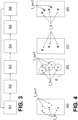
- Fig. 3 schematically illustrated steps are used.
- a subset of the marker molecules is activated by means of a switching signal; they are thus switched from a first state in which they cannot be excited to emit the specific fluorescence radiation to a second state in which they can be excited to emit the specific fluorescence radiation.
- the activation signal can also cause selective deactivation, i.e. an inverse procedure can also be used in step S1. It is important that after step S1 only a subset of the marker molecules can be excited to emit the specific fluorescence radiation.
- the activation or deactivation occurs depending on the marker molecules used.
- the activation occurs through optical radiation, so the switching signal is switching radiation.
- Fig. 4 shows in part (a) the state after step S1. Only a subset of the marker molecules I_n is activated. The marker molecules of this subset are shown with a fully highlighted black dot. The remaining marker molecules were not activated in this step. They are shown in part (a) of the Fig. 4 denoted by l_n+1.
- Labeling molecules that have been activated can then be stimulated to emit fluorescence radiation in a second step S2.
- Fluorescent proteins known from the state of the art such as PA-GFP or DRONPA, are preferably used as fluorescent dyes.
- Such molecules are activated with radiation in the range of 405 nm, excited to emit fluorescence radiation at a wavelength of around 488 nm, and the fluorescence radiation is in a range above 490 nm.
- a third step S3 the emitted fluorescence radiation is detected, for example by integrating the recorded fluorescence photons, so that the fluorescence photons in the sub-image (b) below the Fig. 4 situations shown on the matrix detector 5.
- the diffraction disks of the activated marker molecules I_n do not overlap.
- the size of the diffraction disks is determined by the optical resolution of the image on the matrix detector 5.
- part (b) of the Fig. 4 (theoretical) diffraction disks of fluorescent molecules belonging to the non-activated group I_n+1 are shown. Since these non-activated labeling molecules do not emit any fluorescence radiation, no fluorescence radiation in their (theoretical) diffraction disks interferes the detection of the fluorescence radiation of the subset I_n of the activated label molecules.
- the activation energy is set so that the subset I_n only makes up a comparatively small proportion of the total amount of labeling molecules, so that statistically many labeling molecules can be distinguished in relation to the volume that can be resolved with the optical arrangement.
- a fourth step S4 the position of the fluorescent marker molecules is calculated from the diffraction distribution of the fluorescence disks, whereby the resolution with which the position of the activated marker molecules is known is sharpened beyond the resolution of the optical arrangement, as shown in the partial image (c) of the Fig. 4 shows.
- the non-linearity is preferably selected so that the half-width of the diffraction disk corresponds to a desired spatial resolution for the location of the marking molecules.
- non-linear attenuation can also be used. Fluorescence signals of low amplitude or intensity are attenuated, whereas strong signals remain at least largely undamped.
- a combination of nonlinear amplification and attenuation can also be used.
- a fifth step S5 assembles the marker molecules, whose position has been specified, into a single image whose spatial resolution is increased beyond the optical resolution. However, it only contains information about the previously activated subset of marker molecules.
- step S6 the individual image is adjusted to form an overall image in a known manner.
- the system then returns to step S1, whereby the molecules that were previously fluorescent must be deactivated again.
- deactivation can be achieved by separate radiation or by decaying the activation state. It is possible to bleach already imaged marker molecules by excitation radiation.
- Fig. 4 represented subset I_n+1.
- the overall image is constructed from individual images from the individual runs, which indicate the locations of the marker molecules with a spatial resolution that is sharper than the resolution of the optical image.
- a high-resolution overall image is thus gradually constructed through a corresponding number of iterations.
- the reduction of the diffraction disk is preferably carried out in all three spatial dimensions in the method if several image stacks that are spaced apart in the z direction are recorded.
- the overall image then contains the location of the marker molecules in high resolution in all three spatial directions.
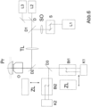
- Fig. 5 shows a schematic of a microscope 6 for high-resolution imaging of a sample 7.
- the sample 7 is, for example, stained with the dye DRONPA (compare WO 2007009812 A1 ).
- the microscope 6 has a radiation source 8 which has individual lasers 9 and 10, whose beams are combined by a beam combiner 11.
- the lasers 9 and 10 can emit radiation at 405 nm (activation radiation) and 488 nm (fluorescence excitation and deactivation), for example.
- Dyes are also known (e.g. the dye called DENDRA (cf. Gurskaya et al., Nature Biotech., Volume 24, pp. 461-465, 2006 )), where activation and fluorescence excitation can occur at one and the same wavelength. In this case, one laser is sufficient.
- An acoustic-optical filter 12 is used for wavelength selection and for quickly switching or attenuating individual laser wavelengths.
- An optics 13 focuses the radiation via a dichroic beam splitter 14 into a pupil of an objective 15, so that the radiation from the radiation source 8 falls on the sample 7 as wide-field illumination.
- Fluorescence radiation generated in the sample 7 is collected via the objective 15.
- the dichroic beam splitter 14 is designed in such a way that it allows the fluorescence radiation to pass through a filter 16 to a tube lens 17, so that the fluorescent sample 7 is imaged onto the detector 5.
- a control device is provided, here designed as a computer 18 with display 19 and keyboard 20.
- the process steps S2 to S6 take place in the computer 18.
- the frame rate of the matrix detector is decisive for the Total measuring time, so that a matrix detector 5 with the highest possible frame rate is advantageous in order to reduce the measuring time.
- a first laser L1 is provided for switching (activating) the dye and lasers L2, L3 are provided for fluorescence excitation / deactivation of dyes in the sample Pr in the wide field and one or more cameras (preferably CCDE) are provided for wide field detection.
- Figures 6 and 8 explain the embodiments according to claim 1 and claim 2 respectively. Further details are shown in Figures 12-14.
- the Figure 7 explains the function of the device according to Fig. 6 .
- Figures 9-11 relate to examples which are not part of the present invention.
- Multi-level detection is defined as an image splitter module according to Fig. 12-14 or an anamorphic image as well as designs of the state of the art ([7,8]).
- ROI regions of interest refers to areas that are preselected automatically or manually, for example based on an overview image, and which can be selectively exposed to radiation.
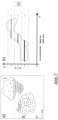
- Figure 6 shows a depth-selective 3D high-resolution fluorescence microscope according to the invention (schematic) in a 2-channel version (for 2 different fluorophores to be observed simultaneously with two cameras K1, K2.
- a point-scanning scan module S follows a laser L1 in the direction of illumination for switching via a 2P excitation, this can be a ps laser diode or even a cw diode laser in the range 780-830nm (or another wavelength suitable for the 2P switching process), the laser L1 is coupled into the illumination beam path via dichroic D1.
- Lasers for wide-field excitation L2 and L3 in different wavelengths are coupled into the illumination beam path via D. Fluorescence detection is carried out via D2 in transmission towards the cameras K1, K2, with a splitting into two color channels for different wavelengths of two fluorophores via D3. For each color, the image can be split using image splitter modules (Bt1 and Bt2) as in Fig. 12-14 described.
- the detection is advantageously carried out using a biplane (multi-plane) detection scheme [7,8], Fig.12-14 for highly precise localization of the molecules also on the z-axis.
- the image is advantageous (see Fig. 12-14 ) through the image splitter modules (Bt1/2 in Figure 6 ) is split in such a way that two partial images are created, each with half the intensity, whose conjugated object planes are offset by, for example, approximately half an axial PSF.
- These partial images are imaged side by side on the camera sensor (K1/K2) and can be evaluated according to [7,8] to determine the z-position of the individual fluorophores from the 2 partial images.
- the switching (photoconversion) of the fluorophores from their non-excitable to their excitable state is carried out via a focused, point-scanned excitation beam, the wavelength of which is chosen so that the switching process occurs through a 2-photon absorption process while the fluorescence excitation and detection of the thus switched fluorophores occurs in the wide field.
- the rasterized activation does not necessarily have to be synchronized with the image recording of the camera.
- the 2P switching advantageously leads to the "sectioning" known from 2-photon microscopy, i.e. the selective excitation of only the molecules in the focal plane.
- a z-resolution comparable to confocal microscopy can be achieved without having to use a confocal pinhole. This means that the method can be easily combined with the camera wide-field detection required for PALM.
- a laser diode operated in picosecond mode can be used (example), or other cost-effective ps laser systems.
- the typical 2P switching wavelengths for the common PALM fluorophores are 760 - 850 nm, a range that is well covered by low-cost semiconductor lasers.
- ROls (Region Of Interest - see DE 198 29 981 A1 define the range within which the fluorophores are activated; with TIRF-PALM, however, all areas of the sample are always activated.
- the method described here can be used to optimally adapt the switching intensity within a frame to the labeling density of the sample (cf. Figure 7a )). This allows the image acquisition time to be reduced, which is particularly important for the acquisition of 3D image stacks.
- the localization rates of areas in the sample marked with different fluorophores can be adjusted to one another.
- a further advantage is that unwanted switching of molecules in sample areas above and below the z-slice to be imaged can be minimized (in addition to the above-mentioned intrinsic sectioning of the 2P excitation) by switching on the activation radiation only in the sample areas with colored structures ( Figure 7 b) ).
- An advantageous method for a sequential process for number-controlled feedback for 2P switching can be carried out.
- the corresponding intensity modulation is output to the scanning 2P switching beam and a next camera image is recorded.
- the described control of the switching intensity is particularly advantageous for samples that are stained with different fluorophores that are measured simultaneously.
- the possibly different switching rates of the different molecules can be adjusted by spatially adjusting the switching intensity, thus reducing the recording time for multi-color measurements.
- the ROIs can be defined based on sample characteristics, or can be laid over the image as a regular grid with fields of suitable size; the latter is particularly advantageous for the versions with wide-field switching illumination (temporal focusing, spinning microlens disc) mentioned below.
- a very high scanning speed of a point scanner may be required, especially for fast image acquisition rates.
- the scanner speed is reduced accordingly. The reduction in peak intensity associated with the line can be accepted due to the low switching intensities required.
- a line scanner can also be used (see also Fig.11 , not part of the invention).
- the low intensities required to switch the dyes also make the use of a scanned line in conjunction with the 2P switching process possible.
- This line can be created, for example, with an anamorphic lens and moved through the object with a one-dimensional scanner.
- the advantage is that a faster scan is possible because only 1D scanning is required.
- the line Since the activation occurs stochastically and is detected in the wide field, the line does not need to be synchronized with the image acquisition.
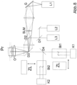
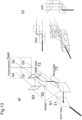
- Figure 8 shows a depth-selective 3D high-resolution microscope according to the invention (schematic) with L1 as activation laser; L2,L2 as excitation laser, a grating G: grating; an SLM: spatial light modulator (see for example DE 199 305 32 A1 ); D1-D4 are dichroic beam splitters or combiners, Bt1 and 2: image splitter modules, K1 and K2 are cameras.
- Fig. 8a the beam path from the light source to the sample is shown enlarged.
- the illumination beam path is drawn with a continuous line and the image is dashed.
- the objective O is schematically represented by a lens.
- the grating is in an intermediate image and is imaged into the next intermediate image (dashed line) in which the SLM is located. This in turn is imaged into the sample Pr.
- the illumination beam (continuous line) of the laser is “offset”.
- the illumination spot Spot is maximally blurred.
- an ROI functionality can be implemented as shown above, with the difference that the respective switching intensity is now set via the SLM in the intermediate image.
- This arrangement advantageously does not require any moving parts (non-scanning) and achieves a similar flexibility as the scanning arrangements described above.
- a grating G is illuminated with the expanded beam of a short-pulse laser L1 with a wavelength suitable for 2P excitation of the switching process.
- the illuminated area of the grating G is then imaged into the sample Pr.
- the grating G splits the spectral components of the laser pulse so that the original short pulse shape is only achieved in the focus of the image (and possibly intermediate images) and accordingly the high peak intensities for the 2P activation process are only present there.
- An SLM as a modulator for the split wavelengths is positioned in an intermediate frame of the image, where the original pulse shape is restored.
- ROIs are created by selectively switching the SLM elements.
- the ROI functionality can now also be used in wide-field excitation (in addition to switching).
- the laser wide-field excitation must also be guided through the SLM or have its own SLM; then the separate definition of ROIs for excitation and switching is also possible.
- This version is available in Figure 8 for the case of 2-color excitation and detection.
- a DMD array can also be used; structure analogous to Figure 8 , but the DMD array must now be used in reflection (again in the intermediate image).
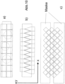
- Figure 9 shows a depth-selective 3D high-resolution microscope (schematic) with scanning microlens disk (SML). The designations are otherwise as in Figure 8 .
- Illumination is provided by a 2P laser L1, for example at around 800 nm (e.g. ps laser diode).
- a 2P laser L1 for example at around 800 nm (e.g. ps laser diode).
- SML scanning microlens array
- the foci of the (rotating) microlenses are imaged into the sample via an intermediate image with an SLM located therein. This creates a rapidly scanned 2P point source for switching the fluorophores with ROl functionality via the SLM.
- the laser wide-field illumination is coupled to excite the fluorophores via dichroic 1 (D1).
- D1 dichroic 1
- the localization-based high-resolution methods described in cannot, in principle, be carried out with a standard LSM: the sub-PSF-accurate localization must be achieved by simultaneous spatial oversampling by the camera pixels, since the molecules only fluoresce for a limited time or are activated at unpredictable times (stochastically). This eliminates a process in which the center of gravity of the molecule is sequentially is determined (raster method).
- the line illumination for switching and/or excitation can also be achieved by a multi-photon process.
- Figure 10 a) shows a principle of localization-based confocal high-resolution microscopy with a line sensor, 10 b) a sensor with an interlocked pixel structure, 10 c) an example for the realization of an interlocked pixel structure with existing pixel geometries by masking.
- Figure 10 a (not part of the invention) explains the principle using a 2-line line sensor (for example the sensor of a line scan camera as often used in machine vision).
- a 2-line line sensor for example the sensor of a line scan camera as often used in machine vision.
- lateral localization (along the row direction) can be achieved by forming a center of gravity or fitting a suitable function (1D Gauss), whereby the interlocking pixels of both rows must be taken into account.
- Localization orthogonal to the row direction can be achieved by forming the difference signal of the corresponding pixels of the opposite pixel rows.
- PSD position sensitive detector
- Figure 10 b) shows a possible sensor structure with two interlocking combs.
- the determined x-position must first be evaluated and taken into account, since the interlocked pixel structure means that the PSD function (y-center of gravity determination) depends on the x-position of the molecule to be localized.
- the line mapping is to be chosen such that the PSF width exactly corresponds to the width of a pixel line; but it is centered on the center of the interlocking comb structure.
- Figure 10 c) shows an alternative implementation proposal based on conventional, square pixel geometries.
- a normal sensor can be rotated by 45 degrees to obtain this pixel orientation.
- an area sensor can also be used for this, which is masked except for the desired line for detection.
- This mask can also be designed as a variable aperture.
- the existing slit aperture in a line scanner is opened slightly in order to capture two rows simultaneously.
- the slit image captured in this way is shown in 10 a ) and b ) .
- the detected area is shown slightly brighter than the hidden area above and below it.
- the center of gravity of the detected molecule can be determined exactly (by the magnitude and sign of the subtraction result).
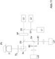
- Figure 11 shows schematically a possible embodiment of a depth-selective high-resolution microscope based on this sensor principle.
- FIG 11 shows a depth-selective 2D high-resolution confocal microscope (schematic) with line scanner, as an example for two-color detection.
- Switching and excitation lasers (L1-L3) are brought into line form by a beam former (SF) and rasterized in one spatial direction (scanner Sx).
- SF beam former
- scanner Sx rasterized in one spatial direction
- the line is confocally imaged onto line detectors (Ld1, Ld2) by appropriate slit apertures as described in the text above.
- D1-D4 are dichroic beam splitters or combiners.
- the line for illumination is generated by the beam shaping optics SF (cylindrical lens) and scanned in one spatial direction (scanner Sx).
- the fluorescence is confocally focused via slit diaphragms B1 and B2 (here an example with two color channels) onto the Fig. 10 sketched line detectors Ld1 and Ld2.
- Fig. 12-14 are advantageous variable image splitter modules Bt1, Bt2 (see e.g. Fig. 6 ) for z-splitting is outlined.
- Fig. 12 shows a wide-field beam path with an expanded light source L1 and a spatially resolved area detector DE, for example a CCD camera.
- the light from the light source L1 is reflected via Dic 1 and the objective O onto a sample Pr.
- the reflected and fluorescent sample light passes through the objective O towards the detection.
- the desired light is selected at the divider Dic 1 and through the filter EF, in this case the reflected light is suppressed, i.e. only the fluorescent light reaches the detection direction.
- the sample light reaches the inventive arrangement of BS, P1 and P2 via SP, L1, L2 and then to the detector DE.
- E1 and E2 are different object planes in the sample Pr.
- Fig. 12a shows an enlarged view of the variable image splitter module BM according to the invention.
- An image of the sample Pr is split into two partial images on the detector DE via the beam splitter cube BS.
- the prism P1 is moved perpendicular to the optical axis by a motor in order to adjust the splitting of the two object planes E1, E2.
- the shifted partial image is reflected back into the continuous beam path via P2 (fixed), spatially offset from the continuous beam path, i.e. laterally offset to DE.
- the image plane e2 of the non-deflected partial image lies on the sensor (partial area S2 of the sensor).
- Fig. 12b enlarged point images of molecules 1, 2, 3 are shown, each from the object planes E1, E2 on the sensor halves S1 and S2.
- the drawing also shows the ray paths of two molecules, both of which are located in object plane E2.
- the aperture B defines the image section reduced to half (corresponding to the size of the sensor halves S1 and S2) and prevents light from outside this area from spilling over into the two partial beam paths.
- the splitting into two partial images takes place at the 50/50 beam splitter cube BS.
- the task of focusing the deflected partial image into an image plane that is different from the directly imaged partial image is fulfilled by the prism P1.
- This prism P1 extends the focal length of the corresponding bundles compared to the corresponding path in air; it is therefore preferably made of a high-refractive glass in order to obtain the largest possible working area. These bundles are reflected back parallel to the direct beam path via the prism P2 and directed onto the image sensor DE in section S1.
- the z-shift of the focal planes of the two partial images from different object planes in the sample can be adjusted.
- the splitting can be advantageously adapted to different lenses.
- the imaging of the object onto the detector by lens L2 in conjunction with the optics L1 to the left of the beam splitter Dic 2 is, overall, advantageously telecentric.
- An adjustable, preferably rectangular aperture B in an intermediate image serves to define a rectangular image area split over P1, P2 and to suppress fluorescence and stray light from the field areas outside this new area.
- a second emission wavelength can be reflected via the color splitter Dic 2 and by using a second, preferably identical z-splitting module and another detector, this beam path can also be used for high-resolution localization.
- Possible longitudinal color errors of the objective O or other chromatic errors that influence the z-localization of the individual molecules can be compensated by adjusting the splitting for the second color channel.
- Fig. 13a shows a further advantageous design of a module for splitting a camera image into 4 partial images of equal intensity for z-high resolution.
- FIG. 13 a On the left, a design with separate mirrors and beam splitters is shown.
- a first splitter T1 here 25/75 split in terms of transmission and reflection, directs part of the light onto the surface Q1 of the detector De4.
- a second part is reflected by T1 and directed via a mirror S1 towards a second splitter T2 with a ratio of 66/33.
- This lets part of the light through towards the surface Q2 of De4 and reflects part towards a mirror S3, which redirects the light towards the 50/50 splitter T3.
- Part passes through T3 onto the surface Q3 of De4 and part is redirected via S3 towards the surface Q4 of De4.
- quadrant Q1 of De4 sees the image in direct passage
- quadrant Q3 by two and quadrant Q4 an image shifted by 3 distances.
- the division ratios of the 3 beam splitters shown here without restriction ensure that all 4 quadrants preferably capture the same intensity.
- Fig. 13 b is a monolithic design with 3 beam splitter cubes for T1-T3 and 3 mirrored prisms for S1-S3 shown from the side, from above and in perspective.
- Fig. 13a The arrangement in Fig. 13a ) and b) is also advantageously suitable for a telecentric detection beam path as shown by Fig. 12 described.
- the advantage is that four images from four sample planes provide four support points for the z-determination, thus enabling more precise z-determination in a larger working range.
- FIG. 14 An advantageous combination of an execution according to Fig. 13 with movable prisms according to Fig. 12 .
- Prisms 1-3 are provided here, which define a light path parallel to the optical axis through a medium of higher optical density. In comparison to Fig. 13 Additional deflection elements 1-3 are used for reflection into the respective partial beam path.
- Each of the three prisms 1-3 which can be adjusted perpendicular to the optical axis (direction of light), is responsible for one quadrant Q2-4 of the sensor De4 ( Fig. 13 ), the fourth quadrant Q1 is illuminated by the direct passage.
- Each prism could now be set to a different plane displacement.
Landscapes
- Physics & Mathematics (AREA)
- Chemical & Material Sciences (AREA)
- General Physics & Mathematics (AREA)
- Optics & Photonics (AREA)
- Health & Medical Sciences (AREA)
- Analytical Chemistry (AREA)
- Immunology (AREA)
- Multimedia (AREA)
- Engineering & Computer Science (AREA)
- Nuclear Medicine, Radiotherapy & Molecular Imaging (AREA)
- Life Sciences & Earth Sciences (AREA)
- Biochemistry (AREA)
- General Health & Medical Sciences (AREA)
- Pathology (AREA)
- Computer Vision & Pattern Recognition (AREA)
- Chemical Kinetics & Catalysis (AREA)
- Investigating, Analyzing Materials By Fluorescence Or Luminescence (AREA)
- Microscoopes, Condenser (AREA)
Applications Claiming Priority (2)
| Application Number | Priority Date | Filing Date | Title |
|---|---|---|---|
| DE102009060793A DE102009060793A1 (de) | 2009-12-22 | 2009-12-22 | Hochauflösendes Mikroskop und Verfahren zur zwei- oder dreidimensionalen Positionsbestimmung von Objekten |
| PCT/EP2010/007595 WO2011085766A1 (de) | 2009-12-22 | 2010-12-14 | Hochauflösendes mikroskop und verfahren zur zwei- oder dreidimensionalen positionsbestimmung von objekten |
Publications (2)
| Publication Number | Publication Date |
|---|---|
| EP2516993A1 EP2516993A1 (de) | 2012-10-31 |
| EP2516993B1 true EP2516993B1 (de) | 2025-02-19 |
Family
ID=43567611
Family Applications (1)
| Application Number | Title | Priority Date | Filing Date |
|---|---|---|---|
| EP10795617.9A Active EP2516993B1 (de) | 2009-12-22 | 2010-12-14 | Hochauflösendes mikroskop und verfahren zur zwei- oder dreidimensionalen positionsbestimmung von objekten |
Country Status (5)
| Country | Link |
|---|---|
| US (1) | US9234846B2 (enExample) |
| EP (1) | EP2516993B1 (enExample) |
| JP (3) | JP2013515249A (enExample) |
| DE (1) | DE102009060793A1 (enExample) |
| WO (1) | WO2011085766A1 (enExample) |
Families Citing this family (45)
| Publication number | Priority date | Publication date | Assignee | Title |
|---|---|---|---|---|
| JPH0742971B2 (ja) | 1990-06-06 | 1995-05-15 | 株式会社青山製作所 | ブランクおよびこのブランクを用いたボルトの製造法 |
| DE102010041794A1 (de) | 2010-09-30 | 2012-04-05 | Carl Zeiss Microlmaging Gmbh | Mikroskopsystem, Mikroskopieverfahren und Computerprogrammprodukt |
| DE102011053232B4 (de) * | 2011-09-02 | 2020-08-06 | Leica Microsystems Cms Gmbh | Mikroskopische Einrichtung und mikroskopisches Verfahren zur dreidimensionalen Lokalisierung von punktförmigen Objekten |
| DE102011055294B4 (de) * | 2011-11-11 | 2013-11-07 | Leica Microsystems Cms Gmbh | Mikroskopische Einrichtung und Verfahren zur dreidimensionalen Lokalisierung von punktförmigen Objekten in einer Probe |
| DE102012201003B4 (de) | 2012-01-24 | 2024-07-25 | Carl Zeiss Microscopy Gmbh | Mikroskop und Verfahren für die hochauflösende 3-D Fluoreszenzmikroskopie |
| GB201217171D0 (en) * | 2012-08-23 | 2012-11-07 | Isis Innovation | Stimulated emission depletion microscopy |
| JP6371289B2 (ja) * | 2012-09-24 | 2018-08-08 | ジーイー・ヘルスケア・バイオサイエンス・コーポレイション | 3次元構造化照明を用いた蛍光確率顕微鏡での位置を解像するための方法及びシステム |
| DE102013102988A1 (de) * | 2013-03-22 | 2014-09-25 | Leica Microsystems Cms Gmbh | Lichtmikroskopisches Verfahren zur Lokalisierung von Punktobjekten |
| WO2014179269A2 (en) * | 2013-04-30 | 2014-11-06 | Molecular Devices, Llc | Apparatus and method for generating in-focus images using parallel imaging in a microscopy system |
| DE102013208415B4 (de) * | 2013-05-07 | 2023-12-28 | Carl Zeiss Microscopy Gmbh | Mikroskop und Verfahren für die 3D-hochauflösende Lokalisierungsmikroskopie |
| DE102013208927A1 (de) * | 2013-05-14 | 2014-11-20 | Carl Zeiss Microscopy Gmbh | Verfahren zur 3D-hochauflösenden Lokalisierungsmikroskopie |
| DE102013208926A1 (de) | 2013-05-14 | 2014-11-20 | Carl Zeiss Microscopy Gmbh | Verfahren zur 3D-hochauflösenden Lokalisierungsmikroskopie |
| DE102013009042A1 (de) * | 2013-05-28 | 2014-12-04 | Carl Zeiss Microscopy Gmbh | Lumineszenzmikroskopie |
| DE102013216124A1 (de) | 2013-08-14 | 2015-02-19 | Carl Zeiss Microscopy Gmbh | Hochauflösende 3D-Fluoreszenzmikroskopie |
| CA2938082A1 (en) | 2013-12-15 | 2015-06-18 | President And Fellows Of Harvard College | Methods and compositions relating to optical super-resolution patterning |
| DE102014002328B4 (de) * | 2014-02-12 | 2021-08-05 | Carl Zeiss Microscopy Gmbh | Multifokales Fluoreszenzrastermikroskop |
| US10352860B2 (en) * | 2014-04-24 | 2019-07-16 | Bruker Nano, Inc. | Super resolution microscopy |
| JP6300658B2 (ja) * | 2014-06-19 | 2018-03-28 | オリンパス株式会社 | 標本観察装置 |
| US20160033411A1 (en) * | 2014-07-29 | 2016-02-04 | President And Fellows Of Harvard College | Methods and compositions relating to storm-based patterning |
| US10006917B2 (en) | 2014-12-15 | 2018-06-26 | President And Fellows Of Harvard College | Methods and compositions relating to super-resolution imaging and modification |
| LU92620B1 (de) * | 2014-12-19 | 2016-06-20 | Leica Microsystems | Rastermikroskop |
| KR101716125B1 (ko) * | 2015-07-20 | 2017-03-15 | 주식회사 토모큐브 | 파면 제어기를 활용한 초고속 고정밀 3차원 굴절률 측정 방법 및 장치 |
| JP6617774B2 (ja) * | 2015-11-27 | 2019-12-11 | 株式会社ニコン | 顕微鏡装置 |
| DE102015016353A1 (de) | 2015-12-16 | 2017-06-22 | Horst Wochnowski | PALM-Verfahren mit mehreren sich nur marginal voneinander unterscheidenden Fluorophoren |
| JP6726687B2 (ja) * | 2015-12-18 | 2020-07-22 | 株式会社堀場製作所 | 粒子分析装置及び粒子分析方法 |
| CN106546513B (zh) * | 2016-11-02 | 2019-04-23 | 中国人民解放军理工大学 | 一种基于正交双视场的三维降水粒子测量与重构装置及方法 |
| JP6784603B2 (ja) * | 2017-01-05 | 2020-11-11 | 東レエンジニアリング株式会社 | 分光測定方法および分光測定装置 |
| CN107167929B (zh) * | 2017-06-12 | 2019-06-25 | 华南师范大学 | 基于dmd的双模式光学超分辨显微成像装置及方法 |
| JP2019066706A (ja) | 2017-10-02 | 2019-04-25 | ソニー株式会社 | 蛍光顕微鏡装置及び蛍光顕微鏡システム |
| JP2019086529A (ja) * | 2017-11-01 | 2019-06-06 | 株式会社ニコン | 顕微鏡、照明装置、及び観察方法 |
| EP3735606B1 (en) * | 2018-01-02 | 2023-03-22 | King's College London | Method and system for localisation microscopy |
| JP7380569B2 (ja) | 2018-08-09 | 2023-11-15 | ソニーグループ株式会社 | 光学顕微鏡装置及び光学顕微鏡システム |
| CN109407295B (zh) * | 2018-12-18 | 2020-07-24 | 中国科学院深圳先进技术研究院 | 一种基于dmd可多色激发的结构光显微系统及多色激发方法 |
| CN113994374B (zh) * | 2019-06-18 | 2025-11-25 | 索高视觉有限公司 | 具有基于局部照射的组合的细化循环的发光成像 |
| DE102019129932B4 (de) * | 2019-11-06 | 2023-12-21 | Technische Universität Braunschweig | Optische Detektionseinrichtung und Verfahren zum Betreiben einer optischen Detektionseinrichtung |
| CN110989186B (zh) * | 2019-12-18 | 2022-03-08 | 苏州显纳精密仪器有限公司 | 一种能在不同环境介质中实现大视场下超分辨成像的上浸没微球透镜组 |
| CN111650739B (zh) * | 2020-05-21 | 2022-06-03 | 中国科学院苏州生物医学工程技术研究所 | 基于dmd的单帧曝光快速三维荧光成像系统及方法 |
| DE102020130476A1 (de) * | 2020-11-18 | 2022-05-19 | MAX-PLANCK-Gesellschaft zur Förderung der Wissenschaften e.V. | Verfahren und Laserscanningmikroskop zum Abbilden einer mit verschiedenen Fluoreszenzmarkern markierten Struktur einer Probe |
| DE102020131047B4 (de) * | 2020-11-24 | 2024-08-22 | Abberior Instruments Gmbh | Verfahren und Vorrichtung zur Aufnahme nanoskopischer Bilder mehrfach gefärbter Proben |
| CN112859315A (zh) * | 2021-01-11 | 2021-05-28 | 北京大学 | 一种多色双模式结构光照明显微成像系统及其成像方法 |
| CN115702777B (zh) * | 2021-08-13 | 2024-05-17 | 深圳先进技术研究院 | 一种多功能双光子显微成像系统 |
| CN113936837B (zh) * | 2021-10-11 | 2023-07-21 | 散裂中子源科学中心 | 一种中子光阑转动切换机构 |
| DE102021134427A1 (de) | 2021-12-22 | 2023-06-22 | Carl Zeiss Microscopy Gmbh | Mikroskop und verfahren zur mikroskopie |
| EP4715441A1 (en) * | 2023-04-21 | 2026-03-25 | Pontificia Universidad Católica de Chile | Method for taking volumetric measurements |
| CN118896940A (zh) * | 2023-05-04 | 2024-11-05 | 深圳先进技术研究院 | 融合光遗传刺激与光信号探测的光学系统及成像装置 |
Citations (2)
| Publication number | Priority date | Publication date | Assignee | Title |
|---|---|---|---|---|
| US20050036667A1 (en) * | 2003-08-15 | 2005-02-17 | Massachusetts Institute Of Technology | Systems and methods for volumetric tissue scanning microscopy |
| WO2009146016A1 (en) * | 2008-04-01 | 2009-12-03 | The Jackson Laboratory | 3d biplane microscopy |
Family Cites Families (32)
| Publication number | Priority date | Publication date | Assignee | Title |
|---|---|---|---|---|
| DE2834204C3 (de) * | 1978-08-04 | 1981-03-19 | Karl Süss KG, Präzisionsgeräte für Wissenschaft und Industrie - GmbH & Co, 8046 Garching | Mikroskop mit zwei Strahlengängen zur gleichzeitigen Scharfeinstellung auf zwei im Abstand befindliche Dingebenen |
| DE4416558C2 (de) | 1994-02-01 | 1997-09-04 | Hell Stefan | Verfahren zum optischen Messen eines Probenpunkts einer Probe und Vorrichtung zur Durchführung des Verfahrens |
| US5866911A (en) | 1994-07-15 | 1999-02-02 | Baer; Stephen C. | Method and apparatus for improving resolution in scanned optical system |
| US5867604A (en) | 1995-08-03 | 1999-02-02 | Ben-Levy; Meir | Imaging measurement system |
| DE19643475C1 (de) * | 1996-10-22 | 1998-06-25 | Laser Applikationan Gmbh | Verfahren zur Geschwindigkeitsmessung nach dem Laser-Doppler-Prinzip |
| US6388788B1 (en) * | 1998-03-16 | 2002-05-14 | Praelux, Inc. | Method and apparatus for screening chemical compounds |
| DE19829981C2 (de) | 1998-07-04 | 2002-10-17 | Zeiss Carl Jena Gmbh | Verfahren und Anordnung zur konfokalen Mikroskopie |
| DE19835072A1 (de) | 1998-08-04 | 2000-02-10 | Zeiss Carl Jena Gmbh | Anordnung zur Beleuchtung und/oder Detektion in einem Mikroskop |
| EP1145066B1 (de) * | 1998-12-21 | 2005-03-02 | Evotec OAI AG | Positionierung des messvolumens in einem scanning-mikroskopischen verfahren |
| JP3099063B2 (ja) * | 1998-12-28 | 2000-10-16 | 大阪大学長 | 多光子顕微鏡 |
| DE19908883A1 (de) | 1999-03-02 | 2000-09-07 | Rainer Heintzmann | Verfahren zur Erhöhung der Auflösung optischer Abbildung |
| DE19930532C2 (de) | 1999-06-30 | 2002-03-28 | Zeiss Carl Jena Gmbh | Anordnung zur Optimierung der Pulsform in einem Laser-Scanning-Mikroskop |
| JP2002062261A (ja) | 2000-08-21 | 2002-02-28 | Olympus Optical Co Ltd | 光学装置および顕微鏡 |
| JP4804665B2 (ja) * | 2001-08-09 | 2011-11-02 | オリンパス株式会社 | レーザ顕微鏡 |
| DE10259443B4 (de) | 2002-12-19 | 2015-01-22 | Carl Zeiss Microscopy Gmbh | Verfahren und Anordnung zur optischen Untersuchung und/oder Bearbeitung einer Probe |
| DE10325459A1 (de) | 2003-04-13 | 2004-11-18 | MAX-PLANCK-Gesellschaft zur Förderung der Wissenschaften e.V. | Räumlich hochaufgelöstes Erzeugen einer dauerhaften Struktur |
| JP4454980B2 (ja) * | 2003-07-11 | 2010-04-21 | オリンパス株式会社 | 顕微鏡の撮像光学系およびそれを用いた顕微鏡 |
| JP2005233802A (ja) * | 2004-02-20 | 2005-09-02 | Yokogawa Electric Corp | 物理量計測装置およびその装置を用いて行う物理量校正方法 |
| JP4709278B2 (ja) | 2005-05-23 | 2011-06-22 | エフ. ヘスス ハラルド | 光変換可能な光学標識を用いる光学顕微鏡法 |
| DE102005027896B4 (de) * | 2005-06-16 | 2012-03-15 | MAX-PLANCK-Gesellschaft zur Förderung der Wissenschaften e.V. | Verfahren zum optischen Messen einer Probe |
| EP1907826B2 (de) | 2005-07-22 | 2020-11-25 | Carl Zeiss MicroImaging GmbH | Auflösungsgesteigerte lumineszenz-mikroskopie |
| DE102006021317B3 (de) * | 2006-05-06 | 2007-10-11 | MAX-PLANCK-Gesellschaft zur Förderung der Wissenschaften e.V. | Verfahren und Fluoreszenzlichtmikroskop zum räumlich hochauflösenden Abbilden einer Struktur einer Probe |
| US7838302B2 (en) * | 2006-08-07 | 2010-11-23 | President And Fellows Of Harvard College | Sub-diffraction limit image resolution and other imaging techniques |
| DE102006047912A1 (de) * | 2006-10-06 | 2008-04-10 | Carl Zeiss Microimaging Gmbh | Verfahren und Anordnung zur parallelisierten mikroskopischen Bildgebung |
| US8217992B2 (en) * | 2007-01-11 | 2012-07-10 | The Jackson Laboratory | Microscopic imaging techniques |
| WO2009085218A1 (en) * | 2007-12-21 | 2009-07-09 | President And Fellows Of Harvard College | Sub-diffraction limit image resolution in three dimensions |
| WO2009098079A1 (en) * | 2008-02-06 | 2009-08-13 | Ludwig-Maximilians-Universität München | Thermo-optical characterisation of nucleic acid molecules |
| WO2009115108A1 (en) * | 2008-03-19 | 2009-09-24 | Ruprecht-Karls-Universität Heidelberg | A method and an apparatus for localization of single dye molecules in the fluorescent microscopy |
| JP2009229715A (ja) * | 2008-03-21 | 2009-10-08 | Olympus Corp | 顕微鏡 |
| DE102008021641A1 (de) * | 2008-04-30 | 2009-11-05 | Carl Zeiss Microlmaging Gmbh | Auflösungsgesteigerte Lumineszenzmikroskopie |
| EP2291641B2 (en) * | 2008-05-21 | 2021-02-17 | Max-Planck-Gesellschaft zur Förderung der Wissenschaften e.V. | High spatial resolution imaging of a structure of interest in a specimen |
| US8948851B2 (en) * | 2009-01-20 | 2015-02-03 | The Trustees Of Dartmouth College | Method and apparatus for depth-resolved fluorescence, chromophore, and oximetry imaging for lesion identification during surgery |
-
2009
- 2009-12-22 DE DE102009060793A patent/DE102009060793A1/de active Pending
-
2010
- 2010-12-14 EP EP10795617.9A patent/EP2516993B1/de active Active
- 2010-12-14 WO PCT/EP2010/007595 patent/WO2011085766A1/de not_active Ceased
- 2010-12-14 US US13/518,064 patent/US9234846B2/en active Active
- 2010-12-14 JP JP2012545135A patent/JP2013515249A/ja active Pending
-
2015
- 2015-06-16 JP JP2015121233A patent/JP6018263B2/ja active Active
-
2016
- 2016-09-29 JP JP2016191256A patent/JP6282706B2/ja active Active
Patent Citations (2)
| Publication number | Priority date | Publication date | Assignee | Title |
|---|---|---|---|---|
| US20050036667A1 (en) * | 2003-08-15 | 2005-02-17 | Massachusetts Institute Of Technology | Systems and methods for volumetric tissue scanning microscopy |
| WO2009146016A1 (en) * | 2008-04-01 | 2009-12-03 | The Jackson Laboratory | 3d biplane microscopy |
Non-Patent Citations (2)
| Title |
|---|
| JONAS FÖLLING ET AL: "Fluorescence Nanoscopy with Optical Sectioning by Two-Photon Induced Molecular Switching using Continuous-Wave Lasers", CHEMPHYSCHEM, vol. 9, no. 2, 1 February 2008 (2008-02-01), DE, pages 321 - 326, XP055329929, ISSN: 1439-4235, DOI: 10.1002/cphc.200700655 * |
| SHROFF H ET AL: "Dual-color superresolution imaging of genetically expressed probes within individual adhesion complexes", PROCEEDINGS OF THE NATIONAL ACADEMY OF SCIENCES, NATIONAL ACADEMY OF SCIENCES, vol. 104, no. 51, 18 December 2007 (2007-12-18), pages 20308 - 20313, XP002540127, ISSN: 0027-8424, DOI: 10.1073/PNAS.0710517105 * |
Also Published As
| Publication number | Publication date |
|---|---|
| WO2011085766A1 (de) | 2011-07-21 |
| JP2015187745A (ja) | 2015-10-29 |
| JP2013515249A (ja) | 2013-05-02 |
| US9234846B2 (en) | 2016-01-12 |
| EP2516993A1 (de) | 2012-10-31 |
| JP6018263B2 (ja) | 2016-11-02 |
| JP6282706B2 (ja) | 2018-02-21 |
| DE102009060793A1 (de) | 2011-07-28 |
| US20130010098A1 (en) | 2013-01-10 |
| JP2017004024A (ja) | 2017-01-05 |
Similar Documents
| Publication | Publication Date | Title |
|---|---|---|
| EP2516993B1 (de) | Hochauflösendes mikroskop und verfahren zur zwei- oder dreidimensionalen positionsbestimmung von objekten | |
| EP2641078B1 (de) | Tiefenauflösungsgesteigerte mikroskopie | |
| EP3295236B1 (de) | Auswertung von signalen der fluoreszenzrastermikroskopie unter verwendung eines konfokalen laserscanning-mikroskops | |
| EP3667391B1 (de) | Mikroskopisches verfahren und mikroskop mit gesteigerter auflösung | |
| EP2444833B1 (de) | SPIM-Mikroskop mit sequenziellem Lightsheet | |
| EP3526634B1 (de) | Optikgruppe für detektionslicht für ein mikroskop, verfahren zur mikroskopie und mikroskop | |
| EP2860566B1 (de) | Hochauflösende Scanning-Mikroskopie | |
| DE102009043744B4 (de) | Verfahren und Mikroskop zur dreidimensional auflösungsgesteigerten Mikroskopie | |
| EP2245494B1 (de) | Vorrichtung und verfahren zum räumlichen hochauflösenden abbilden einer struktur einer probe | |
| EP1264169B1 (de) | Verbesserung der spektralen und/oder räumlichen auflösung in einem laser-scanning mikroskop | |
| EP2480923B1 (de) | Mikroskop | |
| EP1307726B1 (de) | Verfahren zur erfassung des wellenlängenabhängigen verhaltens einer beleuchteten probe | |
| DE102009044983A1 (de) | Mikroskop | |
| DE102009044986A1 (de) | Mikroskop | |
| DE102009060490A1 (de) | Hochauflösendes Mikroskop und Bildteileranordnung | |
| DE10151216A1 (de) | Verfahren zur optischen Erfassung von charakteristischen Größen einer beleuchteten Probe | |
| DE102009044987A1 (de) | Mikroskop | |
| WO2012168065A1 (de) | Hochauflösende lumineszenzmikroskopie | |
| WO2017055405A1 (de) | Hochauflösende scanning-mikroskopie mit der unterscheidung mindestens zweier spektralbereiche | |
| EP4189358B1 (de) | Verfahren zum detektieren von emissionslicht, detektionsvorrichtung und laserscanning-mikroskop | |
| DE102011084315A1 (de) | Hochauflösende Lumineszenzmikroskopie | |
| DE102023100926A1 (de) | Mikroskop | |
| DE102015116598B4 (de) | Verfahren und Mikroskop zur hochauflösenden Abbildung mittels SIM | |
| DE10327382A1 (de) | Verfahren zur Fluoreszenzmikroskopie | |
| DE102023134043A1 (de) | Mikroskop |
Legal Events
| Date | Code | Title | Description |
|---|---|---|---|
| PUAI | Public reference made under article 153(3) epc to a published international application that has entered the european phase |
Free format text: ORIGINAL CODE: 0009012 |
|
| 17P | Request for examination filed |
Effective date: 20120707 |
|
| AK | Designated contracting states |
Kind code of ref document: A1 Designated state(s): AL AT BE BG CH CY CZ DE DK EE ES FI FR GB GR HR HU IE IS IT LI LT LU LV MC MK MT NL NO PL PT RO RS SE SI SK SM TR |
|
| DAX | Request for extension of the european patent (deleted) | ||
| STAA | Information on the status of an ep patent application or granted ep patent |
Free format text: STATUS: EXAMINATION IS IN PROGRESS |
|
| 17Q | First examination report despatched |
Effective date: 20170105 |
|
| GRAP | Despatch of communication of intention to grant a patent |
Free format text: ORIGINAL CODE: EPIDOSNIGR1 |
|
| STAA | Information on the status of an ep patent application or granted ep patent |
Free format text: STATUS: GRANT OF PATENT IS INTENDED |
|
| INTG | Intention to grant announced |
Effective date: 20241127 |
|
| GRAS | Grant fee paid |
Free format text: ORIGINAL CODE: EPIDOSNIGR3 |
|
| GRAA | (expected) grant |
Free format text: ORIGINAL CODE: 0009210 |
|
| STAA | Information on the status of an ep patent application or granted ep patent |
Free format text: STATUS: THE PATENT HAS BEEN GRANTED |
|
| AK | Designated contracting states |
Kind code of ref document: B1 Designated state(s): AL AT BE BG CH CY CZ DE DK EE ES FI FR GB GR HR HU IE IS IT LI LT LU LV MC MK MT NL NO PL PT RO RS SE SI SK SM TR |
|
| REG | Reference to a national code |
Ref country code: GB Ref legal event code: FG4D Free format text: NOT ENGLISH |
|
| RIN1 | Information on inventor provided before grant (corrected) |
Inventor name: WOLLESCHENSKY, RALF Inventor name: KALKBRENNER, THOMAS |
|
| REG | Reference to a national code |
Ref country code: CH Ref legal event code: EP |
|
| REG | Reference to a national code |
Ref country code: DE Ref legal event code: R096 Ref document number: 502010017106 Country of ref document: DE |
|
| REG | Reference to a national code |
Ref country code: IE Ref legal event code: FG4D Free format text: LANGUAGE OF EP DOCUMENT: GERMAN |
|
| REG | Reference to a national code |
Ref country code: NL Ref legal event code: MP Effective date: 20250219 |
|
| PG25 | Lapsed in a contracting state [announced via postgrant information from national office to epo] |
Ref country code: RS Free format text: LAPSE BECAUSE OF FAILURE TO SUBMIT A TRANSLATION OF THE DESCRIPTION OR TO PAY THE FEE WITHIN THE PRESCRIBED TIME-LIMIT Effective date: 20250519 |
|
| PG25 | Lapsed in a contracting state [announced via postgrant information from national office to epo] |
Ref country code: FI Free format text: LAPSE BECAUSE OF FAILURE TO SUBMIT A TRANSLATION OF THE DESCRIPTION OR TO PAY THE FEE WITHIN THE PRESCRIBED TIME-LIMIT Effective date: 20250219 |
|
| PG25 | Lapsed in a contracting state [announced via postgrant information from national office to epo] |
Ref country code: PL Free format text: LAPSE BECAUSE OF FAILURE TO SUBMIT A TRANSLATION OF THE DESCRIPTION OR TO PAY THE FEE WITHIN THE PRESCRIBED TIME-LIMIT Effective date: 20250219 |
|
| PG25 | Lapsed in a contracting state [announced via postgrant information from national office to epo] |
Ref country code: ES Free format text: LAPSE BECAUSE OF FAILURE TO SUBMIT A TRANSLATION OF THE DESCRIPTION OR TO PAY THE FEE WITHIN THE PRESCRIBED TIME-LIMIT Effective date: 20250219 |
|
| REG | Reference to a national code |
Ref country code: LT Ref legal event code: MG9D |
|
| PG25 | Lapsed in a contracting state [announced via postgrant information from national office to epo] |
Ref country code: IS Free format text: LAPSE BECAUSE OF FAILURE TO SUBMIT A TRANSLATION OF THE DESCRIPTION OR TO PAY THE FEE WITHIN THE PRESCRIBED TIME-LIMIT Effective date: 20250619 Ref country code: NO Free format text: LAPSE BECAUSE OF FAILURE TO SUBMIT A TRANSLATION OF THE DESCRIPTION OR TO PAY THE FEE WITHIN THE PRESCRIBED TIME-LIMIT Effective date: 20250519 |
|
| PG25 | Lapsed in a contracting state [announced via postgrant information from national office to epo] |
Ref country code: NL Free format text: LAPSE BECAUSE OF FAILURE TO SUBMIT A TRANSLATION OF THE DESCRIPTION OR TO PAY THE FEE WITHIN THE PRESCRIBED TIME-LIMIT Effective date: 20250219 |
|
| PG25 | Lapsed in a contracting state [announced via postgrant information from national office to epo] |
Ref country code: HR Free format text: LAPSE BECAUSE OF FAILURE TO SUBMIT A TRANSLATION OF THE DESCRIPTION OR TO PAY THE FEE WITHIN THE PRESCRIBED TIME-LIMIT Effective date: 20250219 |
|
| PG25 | Lapsed in a contracting state [announced via postgrant information from national office to epo] |
Ref country code: LV Free format text: LAPSE BECAUSE OF FAILURE TO SUBMIT A TRANSLATION OF THE DESCRIPTION OR TO PAY THE FEE WITHIN THE PRESCRIBED TIME-LIMIT Effective date: 20250219 Ref country code: PT Free format text: LAPSE BECAUSE OF FAILURE TO SUBMIT A TRANSLATION OF THE DESCRIPTION OR TO PAY THE FEE WITHIN THE PRESCRIBED TIME-LIMIT Effective date: 20250620 |
|
| PG25 | Lapsed in a contracting state [announced via postgrant information from national office to epo] |
Ref country code: GR Free format text: LAPSE BECAUSE OF FAILURE TO SUBMIT A TRANSLATION OF THE DESCRIPTION OR TO PAY THE FEE WITHIN THE PRESCRIBED TIME-LIMIT Effective date: 20250520 Ref country code: BG Free format text: LAPSE BECAUSE OF FAILURE TO SUBMIT A TRANSLATION OF THE DESCRIPTION OR TO PAY THE FEE WITHIN THE PRESCRIBED TIME-LIMIT Effective date: 20250219 |
|
| PG25 | Lapsed in a contracting state [announced via postgrant information from national office to epo] |
Ref country code: SE Free format text: LAPSE BECAUSE OF FAILURE TO SUBMIT A TRANSLATION OF THE DESCRIPTION OR TO PAY THE FEE WITHIN THE PRESCRIBED TIME-LIMIT Effective date: 20250219 |
|
| PG25 | Lapsed in a contracting state [announced via postgrant information from national office to epo] |
Ref country code: SM Free format text: LAPSE BECAUSE OF FAILURE TO SUBMIT A TRANSLATION OF THE DESCRIPTION OR TO PAY THE FEE WITHIN THE PRESCRIBED TIME-LIMIT Effective date: 20250219 |
|
| PG25 | Lapsed in a contracting state [announced via postgrant information from national office to epo] |
Ref country code: DK Free format text: LAPSE BECAUSE OF FAILURE TO SUBMIT A TRANSLATION OF THE DESCRIPTION OR TO PAY THE FEE WITHIN THE PRESCRIBED TIME-LIMIT Effective date: 20250219 |
|
| PG25 | Lapsed in a contracting state [announced via postgrant information from national office to epo] |
Ref country code: IT Free format text: LAPSE BECAUSE OF FAILURE TO SUBMIT A TRANSLATION OF THE DESCRIPTION OR TO PAY THE FEE WITHIN THE PRESCRIBED TIME-LIMIT Effective date: 20250219 |
|
| PG25 | Lapsed in a contracting state [announced via postgrant information from national office to epo] |
Ref country code: CZ Free format text: LAPSE BECAUSE OF FAILURE TO SUBMIT A TRANSLATION OF THE DESCRIPTION OR TO PAY THE FEE WITHIN THE PRESCRIBED TIME-LIMIT Effective date: 20250219 Ref country code: EE Free format text: LAPSE BECAUSE OF FAILURE TO SUBMIT A TRANSLATION OF THE DESCRIPTION OR TO PAY THE FEE WITHIN THE PRESCRIBED TIME-LIMIT Effective date: 20250219 |
|
| PG25 | Lapsed in a contracting state [announced via postgrant information from national office to epo] |
Ref country code: RO Free format text: LAPSE BECAUSE OF FAILURE TO SUBMIT A TRANSLATION OF THE DESCRIPTION OR TO PAY THE FEE WITHIN THE PRESCRIBED TIME-LIMIT Effective date: 20250219 |
|
| PG25 | Lapsed in a contracting state [announced via postgrant information from national office to epo] |
Ref country code: SK Free format text: LAPSE BECAUSE OF FAILURE TO SUBMIT A TRANSLATION OF THE DESCRIPTION OR TO PAY THE FEE WITHIN THE PRESCRIBED TIME-LIMIT Effective date: 20250219 |
|
| REG | Reference to a national code |
Ref country code: DE Ref legal event code: R097 Ref document number: 502010017106 Country of ref document: DE |
|
| PLBE | No opposition filed within time limit |
Free format text: ORIGINAL CODE: 0009261 |
|
| STAA | Information on the status of an ep patent application or granted ep patent |
Free format text: STATUS: NO OPPOSITION FILED WITHIN TIME LIMIT |
|
| PGFP | Annual fee paid to national office [announced via postgrant information from national office to epo] |
Ref country code: DE Payment date: 20251211 Year of fee payment: 16 |
|
| 26N | No opposition filed |
Effective date: 20251120 |