EP2513398B1 - Agencement de mécanisme de roulement comprenant un rail de guidage pour porte coulissante - Google Patents
Agencement de mécanisme de roulement comprenant un rail de guidage pour porte coulissante Download PDFInfo
- Publication number
- EP2513398B1 EP2513398B1 EP10801103.2A EP10801103A EP2513398B1 EP 2513398 B1 EP2513398 B1 EP 2513398B1 EP 10801103 A EP10801103 A EP 10801103A EP 2513398 B1 EP2513398 B1 EP 2513398B1
- Authority
- EP
- European Patent Office
- Prior art keywords
- sliding door
- guide
- sliding
- cabinet
- running gear
- Prior art date
- Legal status (The legal status is an assumption and is not a legal conclusion. Google has not performed a legal analysis and makes no representation as to the accuracy of the status listed.)
- Not-in-force
Links
- 230000001360 synchronised effect Effects 0.000 claims description 2
- 238000006073 displacement reaction Methods 0.000 description 27
- 230000005540 biological transmission Effects 0.000 description 5
- 229910052782 aluminium Inorganic materials 0.000 description 2
- XAGFODPZIPBFFR-UHFFFAOYSA-N aluminium Chemical compound [Al] XAGFODPZIPBFFR-UHFFFAOYSA-N 0.000 description 2
- 239000000969 carrier Substances 0.000 description 2
- 238000009434 installation Methods 0.000 description 2
- 229910052751 metal Inorganic materials 0.000 description 2
- 239000002184 metal Substances 0.000 description 2
- 238000007789 sealing Methods 0.000 description 2
- 229910000831 Steel Inorganic materials 0.000 description 1
- 238000004891 communication Methods 0.000 description 1
- 238000009749 continuous casting Methods 0.000 description 1
- 230000001419 dependent effect Effects 0.000 description 1
- 238000013461 design Methods 0.000 description 1
- 238000009826 distribution Methods 0.000 description 1
- 239000000428 dust Substances 0.000 description 1
- 230000007246 mechanism Effects 0.000 description 1
- 238000000034 method Methods 0.000 description 1
- 238000003801 milling Methods 0.000 description 1
- 238000005192 partition Methods 0.000 description 1
- 238000012545 processing Methods 0.000 description 1
- 238000005096 rolling process Methods 0.000 description 1
- 238000010079 rubber tapping Methods 0.000 description 1
- 239000010959 steel Substances 0.000 description 1
- 238000003860 storage Methods 0.000 description 1
- 238000013519 translation Methods 0.000 description 1
Images


Classifications
-
- E—FIXED CONSTRUCTIONS
- E05—LOCKS; KEYS; WINDOW OR DOOR FITTINGS; SAFES
- E05D—HINGES OR SUSPENSION DEVICES FOR DOORS, WINDOWS OR WINGS
- E05D15/00—Suspension arrangements for wings
- E05D15/06—Suspension arrangements for wings for wings sliding horizontally more or less in their own plane
- E05D15/10—Suspension arrangements for wings for wings sliding horizontally more or less in their own plane movable out of one plane into a second parallel plane
- E05D15/1042—Suspension arrangements for wings for wings sliding horizontally more or less in their own plane movable out of one plane into a second parallel plane with transversely moving carriage
-
- E—FIXED CONSTRUCTIONS
- E05—LOCKS; KEYS; WINDOW OR DOOR FITTINGS; SAFES
- E05D—HINGES OR SUSPENSION DEVICES FOR DOORS, WINDOWS OR WINGS
- E05D15/00—Suspension arrangements for wings
- E05D15/06—Suspension arrangements for wings for wings sliding horizontally more or less in their own plane
- E05D15/10—Suspension arrangements for wings for wings sliding horizontally more or less in their own plane movable out of one plane into a second parallel plane
- E05D2015/1028—Suspension arrangements for wings for wings sliding horizontally more or less in their own plane movable out of one plane into a second parallel plane with only the wing moving transversely
- E05D2015/1039—Suspension arrangements for wings for wings sliding horizontally more or less in their own plane movable out of one plane into a second parallel plane with only the wing moving transversely the wing sliding transversely on the carriage
-
- E—FIXED CONSTRUCTIONS
- E05—LOCKS; KEYS; WINDOW OR DOOR FITTINGS; SAFES
- E05Y—INDEXING SCHEME ASSOCIATED WITH SUBCLASSES E05D AND E05F, RELATING TO CONSTRUCTION ELEMENTS, ELECTRIC CONTROL, POWER SUPPLY, POWER SIGNAL OR TRANSMISSION, USER INTERFACES, MOUNTING OR COUPLING, DETAILS, ACCESSORIES, AUXILIARY OPERATIONS NOT OTHERWISE PROVIDED FOR, APPLICATION THEREOF
- E05Y2201/00—Constructional elements; Accessories therefor
- E05Y2201/40—Motors; Magnets; Springs; Weights; Accessories therefor
- E05Y2201/404—Function thereof
- E05Y2201/41—Function thereof for closing
- E05Y2201/412—Function thereof for closing for the final closing movement
-
- E—FIXED CONSTRUCTIONS
- E05—LOCKS; KEYS; WINDOW OR DOOR FITTINGS; SAFES
- E05Y—INDEXING SCHEME ASSOCIATED WITH SUBCLASSES E05D AND E05F, RELATING TO CONSTRUCTION ELEMENTS, ELECTRIC CONTROL, POWER SUPPLY, POWER SIGNAL OR TRANSMISSION, USER INTERFACES, MOUNTING OR COUPLING, DETAILS, ACCESSORIES, AUXILIARY OPERATIONS NOT OTHERWISE PROVIDED FOR, APPLICATION THEREOF
- E05Y2201/00—Constructional elements; Accessories therefor
- E05Y2201/40—Motors; Magnets; Springs; Weights; Accessories therefor
- E05Y2201/47—Springs
- E05Y2201/488—Traction springs
-
- E—FIXED CONSTRUCTIONS
- E05—LOCKS; KEYS; WINDOW OR DOOR FITTINGS; SAFES
- E05Y—INDEXING SCHEME ASSOCIATED WITH SUBCLASSES E05D AND E05F, RELATING TO CONSTRUCTION ELEMENTS, ELECTRIC CONTROL, POWER SUPPLY, POWER SIGNAL OR TRANSMISSION, USER INTERFACES, MOUNTING OR COUPLING, DETAILS, ACCESSORIES, AUXILIARY OPERATIONS NOT OTHERWISE PROVIDED FOR, APPLICATION THEREOF
- E05Y2201/00—Constructional elements; Accessories therefor
- E05Y2201/60—Suspension or transmission members; Accessories therefor
- E05Y2201/604—Transmission members
-
- E—FIXED CONSTRUCTIONS
- E05—LOCKS; KEYS; WINDOW OR DOOR FITTINGS; SAFES
- E05Y—INDEXING SCHEME ASSOCIATED WITH SUBCLASSES E05D AND E05F, RELATING TO CONSTRUCTION ELEMENTS, ELECTRIC CONTROL, POWER SUPPLY, POWER SIGNAL OR TRANSMISSION, USER INTERFACES, MOUNTING OR COUPLING, DETAILS, ACCESSORIES, AUXILIARY OPERATIONS NOT OTHERWISE PROVIDED FOR, APPLICATION THEREOF
- E05Y2201/00—Constructional elements; Accessories therefor
- E05Y2201/60—Suspension or transmission members; Accessories therefor
- E05Y2201/606—Accessories therefor
- E05Y2201/62—Synchronisation of suspension or transmission members
-
- E—FIXED CONSTRUCTIONS
- E05—LOCKS; KEYS; WINDOW OR DOOR FITTINGS; SAFES
- E05Y—INDEXING SCHEME ASSOCIATED WITH SUBCLASSES E05D AND E05F, RELATING TO CONSTRUCTION ELEMENTS, ELECTRIC CONTROL, POWER SUPPLY, POWER SIGNAL OR TRANSMISSION, USER INTERFACES, MOUNTING OR COUPLING, DETAILS, ACCESSORIES, AUXILIARY OPERATIONS NOT OTHERWISE PROVIDED FOR, APPLICATION THEREOF
- E05Y2201/00—Constructional elements; Accessories therefor
- E05Y2201/60—Suspension or transmission members; Accessories therefor
- E05Y2201/622—Suspension or transmission members elements
- E05Y2201/64—Carriers
-
- E—FIXED CONSTRUCTIONS
- E05—LOCKS; KEYS; WINDOW OR DOOR FITTINGS; SAFES
- E05Y—INDEXING SCHEME ASSOCIATED WITH SUBCLASSES E05D AND E05F, RELATING TO CONSTRUCTION ELEMENTS, ELECTRIC CONTROL, POWER SUPPLY, POWER SIGNAL OR TRANSMISSION, USER INTERFACES, MOUNTING OR COUPLING, DETAILS, ACCESSORIES, AUXILIARY OPERATIONS NOT OTHERWISE PROVIDED FOR, APPLICATION THEREOF
- E05Y2201/00—Constructional elements; Accessories therefor
- E05Y2201/60—Suspension or transmission members; Accessories therefor
- E05Y2201/622—Suspension or transmission members elements
- E05Y2201/706—Shafts
-
- E—FIXED CONSTRUCTIONS
- E05—LOCKS; KEYS; WINDOW OR DOOR FITTINGS; SAFES
- E05Y—INDEXING SCHEME ASSOCIATED WITH SUBCLASSES E05D AND E05F, RELATING TO CONSTRUCTION ELEMENTS, ELECTRIC CONTROL, POWER SUPPLY, POWER SIGNAL OR TRANSMISSION, USER INTERFACES, MOUNTING OR COUPLING, DETAILS, ACCESSORIES, AUXILIARY OPERATIONS NOT OTHERWISE PROVIDED FOR, APPLICATION THEREOF
- E05Y2800/00—Details, accessories and auxiliary operations not otherwise provided for
- E05Y2800/20—Combinations of elements
- E05Y2800/205—Combinations of elements forming a unit
-
- E—FIXED CONSTRUCTIONS
- E05—LOCKS; KEYS; WINDOW OR DOOR FITTINGS; SAFES
- E05Y—INDEXING SCHEME ASSOCIATED WITH SUBCLASSES E05D AND E05F, RELATING TO CONSTRUCTION ELEMENTS, ELECTRIC CONTROL, POWER SUPPLY, POWER SIGNAL OR TRANSMISSION, USER INTERFACES, MOUNTING OR COUPLING, DETAILS, ACCESSORIES, AUXILIARY OPERATIONS NOT OTHERWISE PROVIDED FOR, APPLICATION THEREOF
- E05Y2800/00—Details, accessories and auxiliary operations not otherwise provided for
- E05Y2800/20—Combinations of elements
- E05Y2800/21—Combinations of elements of identical elements, e.g. of identical compression springs
-
- E—FIXED CONSTRUCTIONS
- E05—LOCKS; KEYS; WINDOW OR DOOR FITTINGS; SAFES
- E05Y—INDEXING SCHEME ASSOCIATED WITH SUBCLASSES E05D AND E05F, RELATING TO CONSTRUCTION ELEMENTS, ELECTRIC CONTROL, POWER SUPPLY, POWER SIGNAL OR TRANSMISSION, USER INTERFACES, MOUNTING OR COUPLING, DETAILS, ACCESSORIES, AUXILIARY OPERATIONS NOT OTHERWISE PROVIDED FOR, APPLICATION THEREOF
- E05Y2800/00—Details, accessories and auxiliary operations not otherwise provided for
- E05Y2800/73—Multiple functions
-
- E—FIXED CONSTRUCTIONS
- E05—LOCKS; KEYS; WINDOW OR DOOR FITTINGS; SAFES
- E05Y—INDEXING SCHEME ASSOCIATED WITH SUBCLASSES E05D AND E05F, RELATING TO CONSTRUCTION ELEMENTS, ELECTRIC CONTROL, POWER SUPPLY, POWER SIGNAL OR TRANSMISSION, USER INTERFACES, MOUNTING OR COUPLING, DETAILS, ACCESSORIES, AUXILIARY OPERATIONS NOT OTHERWISE PROVIDED FOR, APPLICATION THEREOF
- E05Y2900/00—Application of doors, windows, wings or fittings thereof
- E05Y2900/20—Application of doors, windows, wings or fittings thereof for furniture, e.g. cabinets
Definitions
- the subject of the present invention is a drive arrangement with a guide rail for a sliding door according to the preamble of patent claim 1.
- Sliding doors are used to make a cabinet accessible without requiring space for swinging out the doors. Often, more than two sliding doors are provided for closing a cabinet when the latter exceeds a certain width. Such known sliding doors move to mounted on the ceiling and / or in the bottom of the cabinet rails. If a sliding door is opened, it comes to lie in front of or behind the adjacent sliding door. A disadvantage of these sliding doors is the fact that no optimal sealing of the cabinet interior is possible. Furthermore, parallel sliding doors are often not aesthetically pleasing.
- the sliding doors are each held by a displacement device, which is arranged above the cabinet or under the cabinet and is guided on two spaced, individually bolted to the cabinet rails.
- a guide curve is mounted on the cabinet or under this, in which a guide member attached to the displacement device engages to trigger the predetermined parallel offset.
- further guidance means are necessary. These are activated by suitable synchronization elements from the support side.
- a groove must be inserted, in which a guide member is pivotally mounted and guided. A smooth shift and also an exact parallel guidance of the sliding doors is thus called into question. Because of the imperfect guidance, the sliding doors must be displaced strongly in parallel by the carrying device in order to prevent mutual contact during the lateral displacement.
- An object of the present invention is therefore to provide a drive assembly with a guide rail for parallel sliding doors, which eliminates the disadvantages of the known and is possible with a smooth-running, simple design and mountable with little effort by the carpenter mechanics.
- the merger of the two parallel rails for the storage of the displacement device in the longitudinal displacement to a single made of folded sheet metal or preferably made as extruded aluminum, allows the manufacturer of sliding door cabinets (carpenters, furniture factories) in the simplest way the rails on or under a To mount the cabinet, the manufacturer must specify during installation only the distance of this single monobloc element to the front edge of the cabinet. He can also insert the guide cam in the rail element and he only needs to measure the location of the attachment of the sliding door to the displacement device and to fix the guide curve with a screw.
- the Rail element can also be narrower, ie, the two rails can be closer together than in the known displacement devices, whereby the rail element is also mounted on cabinets with shallow depth.
- the displacement device can also be divided into two sections.
- the guide means for the edge of the sliding door further spaced from the displacement device are very simply constructed and fastened to the rear side of the sliding door.
- On the cabinet itself is to attach only the device for transmitting the movement from top to bottom.
- no recesses and the like must be attached to the cabinet so that an optimal all-round sealing of the sliding doors can be achieved with closed sliding doors.
- the height of the displacement device can be reduced compared to the known embodiments, which leads to a gain in the interior of the cabinet. Consequently, with the sliding device according to the invention, sliding doors according to the invention can be attached to each cabinet, eg also existing built-in wardrobes intended for swing doors, without further intervention, such as attaching grooves for guide rails.
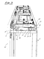
- FIG. 1 a cabinet 1 with two side walls 3, two partitions 5, a bottom 7 and a ceiling 9 and a rear wall 11 is shown. All elements of the cabinet 1 consist of rectangular blanks. There are for the installation of an inventive drive assembly for sliding doors 15 no adjustments such as cuts, grooves for guide rails, breakthroughs, etc. required.
- FIG. 2 showing the right upper half of the cabinet 1, the right side wall 3 is pulled out as a side termination for the drive assembly 13 above the ceiling 9.
- a displacement device 13 with a cover 17 can be seen on the top of the ceiling 9, a displacement device 13 with a cover 17 can be seen. The latter serves as dust protection for the underlying functional elements of the displacement device 13.
- the cover 17 also serves as an upper pivot bearing for a shaft 45 (FIG. FIG.
- the sliding device 13 is mounted on a rail element 19 which extends over the entire width of the cabinet 1 and is fixed on the ceiling 9 or below the floor 7.
- the rail member 19 includes laterally each a lower roller conveyor 21 for the mass of the sliding door 15th receiving carrying rollers 23.
- the support rollers 23 are easily rotatably mounted on horizontal shafts or stub shafts.
- upper roller conveyors 25 are formed, which are arranged parallel to the lower roller conveyors 21 and spaced therefrom, which is only slightly larger than the diameter of the support rollers 23. Between the roller conveyors 21, 25 are in a constant Distance from each other, two further guideways 27 formed between paired vertical legs 29.
- each guide track 27 serves for the lateral guidance of guide rollers 31, which are rotatably mounted about vertical axes and the displacement device 13 laterally guide exactly.
- the distance between the two legs 29 of each guide track 27 is again slightly larger than the diameter of the guide rollers 31, such that they are guided almost free of play, ie that these are each in contact with one of the two legs 29 when rolling, depending on the forces acting on the displacement device 13.
- the rail element 19, with the features listed above, is preferably produced as a continuous casting of aluminum. It could of course also be produced as a sheet metal bent part made of steel.
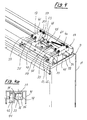
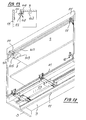
- the displacement device 13 further comprises two spaced apart through the cover 17th connected cross member 33, at the ends of the four support rollers 23 are mounted ( FIGS. 3 to 5 ).
- an open-top guide channel 35 is formed with pairwise opposite, mutually parallel side walls 37. In this engage from above each two spaced-apart, about vertical axes rotatably mounted rollers 39 a.
- the rollers 39 are attached to roller carriers 41.
- the rollers 39 are located with a small clearance between the side walls 37.
- the two roller supports 41 are bolted to the top with screws 40 serving as a cover 17.
- On roller carrier 41 four support rollers 42 are further rotatably mounted on horizontal axes.
- the support rollers 42 are guided at the top and bottom in a laterally formed on the roller carrier 41 track 44 ( FIG. 4a ).
- a shaft 45 is further attached as a pivot bearing for a sleeve 43.
- a lever 47 is pivotally mounted, the free end carries a support roller 55.
- a cam roller 48 is arranged at the lower end of the shaft 45.
- the guide plate 51 comprises on its surface over about 90 ° extending cam track 53, in which the cam roller 48 is guided on both sides.
- the cam roller 48 is rotatably mounted at the lower end of the shaft 45 and protrudes into the cam track 53.
- a recess 57 which is open in the sliding direction and into which the support roller 55 retracts when the displacement device 13 slides over the guide plate 51 when the sliding door 15 is closed.
- the guide plate 51 is held in the vertical direction and in the horizontal by the leg 29 of the roller conveyor 27.
- the guide plate 51 In the direction of travel of the sliding doors 15, the guide plate 51 is held by the screwed into the base plate 49, preferably self-tapping screw 59.
- the guide plate 51 is fixed on the rail member 19 before or after the attachment of the rail member 19 to the cabinet 1.
- the cover 17, to which the cross members 33 are attached, is characterized by at least one spring (not shown) FIG. 4 pulled into the retracted position.
- An in FIG. 5 shown spring 61 which is connected to the end of the control lever 47 and the cover 17, serves to hold the lever 47 in a direction perpendicular to the direction of travel of the sliding doors 15 aligned position or to pull in this position.
- a mounting rail 63 is fastened with screws in the region of the upper edge.
- retaining pin 65 are arranged with conical circumferential grooves.
- the retaining pins 65 engage in closely dimensioned bores 67 on a retaining strip 69.
- About the horizontal holes 67 in the retaining strip 69 are at right angles screwed into threaded holes locking screws 71, with which the retaining pin 65 can be fixed without play in the retaining strip 69.
- the retaining strip 69 is held on the cover 17 by suitable means, such as screws 70, both in the vertical and horizontal adjustable to align the sliding door 15 to the cabinet 1 can.
- the sliding door 15 is pulled away from its closed position, ie adjacent to the leading edges of the walls of the cabinet 1, vertically from the cabinet 1.
- the cam roller 48 slides the initially perpendicular to the rail member 19 extending, then arcuate cam track 53 along from the position according to FIG. 4 in the position according to FIG. 5 ,
- the support roller 55 still remains in the recess 57. This is done at the beginning of the pulling movement only a parallel displacement of the sliding door 15 away from the front of the cabinet.
- the adjusting lever 47 rotates about the axis of rotation of the remaining in the recess 57 support roller 55. Thereafter, the sliding door 15 can move to the left and are the interior of the cabinet 1 free. The sliding door 15 can now be pushed so far to the left until essentially complete overlap with the adjacent sliding door 15 is done. During the sliding movement, the support roller rolls on the leg 29 of the rear guide track 27 from. If the sliding door 15 is closed, ie shifted to the right, the support roller 55 runs into the recess 57 at the end of the sliding movement. Thereafter, the cam roller 48 slides into the cam track 53 and pulls the sliding door 15 in translation to the cabinet 1 zoom. Due to the straight last section at the end of the cam track 53, the sliding door 15 can not open by itself, ie move to the left, but only after the Nachvorne endeavour, which is done manually or electrically in an electric drive.
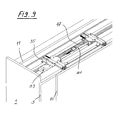
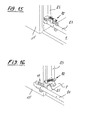
- a synchronization and support device 72 attached.
- This comprises a mounting plate 73, on which a transmission shaft 83 is pivotally mounted and held axially by a bridge 75.
- a pivot lever 85 is rotatably disposed on the free end of a roller carrier 77 is pivotally supported about a vertical axis 87.
- roller carrier 77 two support rollers 79 are at the top and at the bottom a guide roller 79 rotatably mounted on horizontal axes.
- the holding rollers 79 rest on the top and on the bottom edge of a guide strip 81 fastened to the inside of the sliding door 15, wherein the top holding rollers 79 have a recess, so that the rollers can partially surround the top edge 81 'of the guide rail 81.
- An identically formed synchronization device 71 is also fixed in the area of the ceiling 9 of the cabinet 1 to the intermediate wall 5 and engages there in a guide bar 81, which is connected by screws to the sliding door 15.
- a tension spring 95 is attached at its first end. The second end of the tension spring 95 is connected to the roller carrier 77.
- the transmission shaft 83 rotates because of the two roller carriers 77, which with the sliding door 15 are in communication via the guide rails 81, are led to the outside. This ensures that the upper and lower edges of the sliding door 15 simultaneously, ie synchronously, also participate in the translational displacement.
- the synchronization device 72 thus ensures the parallelism of the translational displacement of the sliding door 15.
- the synchronization device 72 also serves to support the sliding door 15 at the edge remote from the displacement device 13. In each position of the sliding door 15, the lower retaining roller 79 carries the sliding door 15 via the guide strip 81 and thus prevents a torque on the drive assembly 13.
- two drive arrangements can be arranged next to one another at a distance from one another for better load distribution and avoidance of large torque on the drive arrangement.
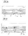
- FIG. 8 occurs in place of a single control lever 47, a further one which, via a synchronization element in the form of a toothed belt 97, the pivoting movements of the two levers 47 is equal.
- the timing belt 97 meshes with two pinions 99, which are non-rotatably attached to the levers 47.
- the pinion 99 sit on that end of the lever 47, which by the cam track 53 when lifting the Sliding door 15 is pivoted about 90 ° clockwise.
- FIG. 9 occurs in place of a toothed belt 97, a link rod 101, the ends of which are pivotally connected to the ends of the two levers 47.
- the roller carrier 77 is in turn secured to the transmission shaft 83 via the boom 85.
- the transmission shaft 83 connects a further roller carrier 77, which is formed and fixed on a rail 81 in the region of the upper edge of the sliding door in the same manner.
- a plate 103 with a guide groove 105 can be attached to the ceiling 9 of the cabinet 1, a plate 103 with a guide groove 105.
- the guide groove 105 engages a hinged to the sliding door 15 guide lever 107 a.
- the guide groove 105 in the plate 103 is connected to a parallel to the front edge of the cabinet 1 extending guide rail 109.
- the guide lever 107 is pivotally hinged to a support bracket 111 and carries at its free end a retaining roller 113, which is guided when moving the sliding door in the guide rail 109 and at the end of the sliding movement, when the sliding door 15 moves from the extended to the retracted position, slides out of the guide rail 109 in the guide groove 105 and is held there by a spring on the guide lever in the retracted position or is urged by the spring in the retracted position.
- Displacement device 13 at the bottom of a cabinet, in particular a sideboard, the upper edge fed to the cabinet 1 at.
- the guide lever 7 serves to ensure that the sliding door 15 is always guided at a constant distance from the front edge of the cabinet, even if a person in the area of the sliding door corner holds it and shifts it ( FIGS. 12 and 13 ).
- Shifters shown 13 are each mounted on the ceiling 9 of the cabinet, ie, the sliding door 15 depends on the displacement device 13.
- a sliding device 13 To attach invisible to a low cabinet, such as a sideboard, a sliding device 13, the latter from below the bottom of the bottom. 7 be attached.
- the support rollers 23 are then on the upper roller conveyor 25 and carry the sliding door 15 ( FIG. 14 ).
Landscapes
- Engineering & Computer Science (AREA)
- Mechanical Engineering (AREA)
- Support Devices For Sliding Doors (AREA)
- Drawers Of Furniture (AREA)
- Power-Operated Mechanisms For Wings (AREA)
Claims (5)
- Agencement de mécanisme de roulement, avec deux rails de guidage (21) s'étendant en parallèle pour une porte coulissante (15) et avec un dispositif d'avancement en parallèle pour le mouvement coulissant latéral et pour dégager la porte coulissante (15) d'une ouverture de porte d'une armoire (1) en la soulevant, comprenant un dispositif de coulissement (13) mobile en coulissement sur les rails (21), un support (33) pouvant être déplacé sur le dispositif de coulissement (13) perpendiculairement à la direction de coulissement, et un élément de guidage fixé sur le support (33), élément qui est destiné à s'engager dans une piste de came (53) disposée entre les rails de guidage (21) et qui assure l'avancement en parallèle pendant le coulissement latéral de la porte coulissante (15),
caractérisé en ce que l'élément de guidage comprend un arbre (45) fixé sur le support (33), arbre auquel un levier de commande (47) est articulé à pivotement,
en ce qu'un galet de soutien (55) est disposé à l'extrémité libre du levier de commande (47) comme moyen de guidage,
en ce qu'un galet de came (48) est monté à l'extrémité inférieure de l'arbre (45), galet qui est destiné à s'engager dans la piste de came (53) prévue sur une plaque de guidage (51) sur l'armoire (1),
en ce que l'axe de rotation du galet de soutien (55) sert d'axe de pivotement du levier de commande (47) pendant le déplacement en parallèle,
en ce que le galet de came (48) est, pendant l'avancement en parallèle de la porte coulissante (15), guidé dans la piste de came (53) s'étendant sur un angle supérieur à 90°, et en ce que le galet de soutien (55) est, pendant l'avancement en parallèle, maintenu à poste fixe dans un évidement (57) prévu sur la plaque de guidage (51) et ouvert d'un côté dans la direction de coulissement de la porte coulissante (15),
et en ce que le levier de commande (47), après l'avancement en parallèle, est maintenu par un ressort (61) dans une position sensiblement perpendiculaire à l'allure des voies de guidage (29) pour le dispositif de coulissement (13), et le galet de soutien (55) s'applique contre la voie de guidage (29) pendant le coulissement latéral de la porte coulissante (15) et guide la porte coulissante (15) dans sa position dégagée de l'armoire (1) par soulèvement. - Agencement de mécanisme de roulement selon la revendication 1, caractérisé en ce que l'arbre (45) est fixé par son extrémité supérieure sur le dessous d'un élément de recouvrement (17) recouvrant le support (33).
- Agencement de mécanisme de roulement selon la revendication 1 ou 2, caractérisé en ce que deux leviers de commande (47) sont disposés à distance l'un de l'autre sur le dispositif de coulissement (13), et leur mouvement de pivotement est synchronisé par un moyen de liaison.
- Agencement de mécanisme de roulement selon la revendication 3, caractérisé en ce que, comme moyen de liaison pour les leviers de commande (47), une courroie dentée (97) s'enroule autour de deux pignons (99) fixés sur les arbres (45) qui portent les leviers de commande (47).
- Agencement de mécanisme de roulement selon la revendication 3, caractérisé en ce que, comme moyen de liaison pour les leviers de commande (47), une tige articulée (101) relie entre eux de manière articulée les deux leviers de commande (47).
Priority Applications (1)
| Application Number | Priority Date | Filing Date | Title |
|---|---|---|---|
| EP13004804.4A EP2687661B1 (fr) | 2009-12-18 | 2010-12-17 | Agencement de mécanisme de roulement comprenant un rail de guidage pour porte coulissante |
Applications Claiming Priority (2)
| Application Number | Priority Date | Filing Date | Title |
|---|---|---|---|
| CH01950/09A CH702441A1 (de) | 2009-12-18 | 2009-12-18 | Laufwerksanordnung mit zwei Führungsschienen für eine Schiebetür. |
| PCT/CH2010/000315 WO2011079400A1 (fr) | 2009-12-18 | 2010-12-17 | Agencement de mécanisme de roulement comprenant un rail de guidage pour porte coulissante |
Related Child Applications (2)
| Application Number | Title | Priority Date | Filing Date |
|---|---|---|---|
| EP13004804.4A Division EP2687661B1 (fr) | 2009-12-18 | 2010-12-17 | Agencement de mécanisme de roulement comprenant un rail de guidage pour porte coulissante |
| EP13004804.4A Division-Into EP2687661B1 (fr) | 2009-12-18 | 2010-12-17 | Agencement de mécanisme de roulement comprenant un rail de guidage pour porte coulissante |
Publications (2)
| Publication Number | Publication Date |
|---|---|
| EP2513398A1 EP2513398A1 (fr) | 2012-10-24 |
| EP2513398B1 true EP2513398B1 (fr) | 2014-12-03 |
Family
ID=43735206
Family Applications (2)
| Application Number | Title | Priority Date | Filing Date |
|---|---|---|---|
| EP10801103.2A Not-in-force EP2513398B1 (fr) | 2009-12-18 | 2010-12-17 | Agencement de mécanisme de roulement comprenant un rail de guidage pour porte coulissante |
| EP13004804.4A Not-in-force EP2687661B1 (fr) | 2009-12-18 | 2010-12-17 | Agencement de mécanisme de roulement comprenant un rail de guidage pour porte coulissante |
Family Applications After (1)
| Application Number | Title | Priority Date | Filing Date |
|---|---|---|---|
| EP13004804.4A Not-in-force EP2687661B1 (fr) | 2009-12-18 | 2010-12-17 | Agencement de mécanisme de roulement comprenant un rail de guidage pour porte coulissante |
Country Status (9)
| Country | Link |
|---|---|
| US (1) | US8763205B2 (fr) |
| EP (2) | EP2513398B1 (fr) |
| JP (1) | JP5762438B2 (fr) |
| CN (1) | CN102713120B (fr) |
| BR (1) | BR112012014840A2 (fr) |
| CH (1) | CH702441A1 (fr) |
| DE (1) | DE212010000193U1 (fr) |
| ES (2) | ES2604029T3 (fr) |
| WO (1) | WO2011079400A1 (fr) |
Families Citing this family (39)
| Publication number | Priority date | Publication date | Assignee | Title |
|---|---|---|---|---|
| ITTV20110071A1 (it) * | 2011-05-23 | 2012-11-24 | Bortoluzzi Lab S R L | Dispositivo per ante scorrevoli a chiusura complanare, particolarmente per mobili e simili |
| ITCO20110048A1 (it) * | 2011-10-18 | 2013-04-19 | Mixal S R L | Gruppo di scorrimento di una anta di un mobile e mobile che lo utilizza |
| KR101249976B1 (ko) * | 2012-11-23 | 2013-04-03 | (주)지씨아이 | 미닫이식 도어의 개폐장치 |
| DE102013110013A1 (de) * | 2013-04-30 | 2014-10-30 | Hettich-Heinze Gmbh & Co. Kg | Funktionsbeschlag für eine Schiebetür |
| DE102013104436A1 (de) | 2013-04-30 | 2014-10-30 | Hettich-Heinze Gmbh & Co. Kg | Schiebetürbeschlag für ein Möbel |
| ITMI20130759A1 (it) * | 2013-05-09 | 2014-11-10 | Effegi Brevetti Srl | Dispositivo di apertura per ante complanari |
| DE102013108848A1 (de) | 2013-08-15 | 2015-02-19 | Hettich-Heinze Gmbh & Co. Kg | Schiebetürbeschlag und Möbel |
| EP2886764A1 (fr) * | 2013-12-23 | 2015-06-24 | Vapor Europe S.r.l. A Wabtec Company | Dispositif de montage pour panneau de porte |
| CN105025673B (zh) * | 2014-04-21 | 2017-12-15 | 上海宽带技术及应用工程研究中心 | 一种适用于高密度机房的机柜滑动门 |
| US9282831B2 (en) * | 2014-05-16 | 2016-03-15 | Cierreesse S.R.L. | Food display counter |
| DE202014103102U1 (de) * | 2014-07-07 | 2015-10-12 | Grass Gmbh | Vorrichtung zur Bewegungsführung eines Schubelements und Kücheneinrichtung |
| WO2016016794A1 (fr) * | 2014-08-01 | 2016-02-04 | Calistri Giacinto S.N.C. Di Calistri Claudio, Roberto, Sauro & C. | Appareil de mouvement pour portes |
| US20160066689A1 (en) * | 2014-09-09 | 2016-03-10 | TERNO SCORREVOLI s.r.I. | Device for the support and safe movement of cabinet doors |
| PL3204583T3 (pl) * | 2014-10-12 | 2022-08-08 | Bortoluzzi Sistemi S.P.A. | Mebel z mechanizmem przesuwnego skrzydła |
| EP3088646B1 (fr) | 2015-04-27 | 2020-02-19 | Hawa Sliding Solutions AG | Dispositif de guidage pour une porte coulissante |
| EP3088645B1 (fr) | 2015-04-27 | 2018-06-27 | Hawa Sliding Solutions AG | Dispositif de liaison pour une porte coulissante |
| EP3088647B1 (fr) | 2015-04-27 | 2021-02-24 | Hawa Sliding Solutions AG | Système à rails pour un dispositif de guidage |
| CN106322877A (zh) * | 2015-06-30 | 2017-01-11 | 青岛海高设计制造有限公司 | 冰箱 |
| CN105466124B (zh) * | 2015-12-29 | 2018-03-23 | 青岛海尔股份有限公司 | 一种用于冰箱门体的引导组件及冰箱 |
| DE102016101118A1 (de) * | 2016-01-22 | 2017-07-27 | Hettich-Heinze Gmbh & Co. Kg | Möbel |
| US9896871B2 (en) * | 2016-02-16 | 2018-02-20 | Vantage Mobility International, Llc | Method of extending opening ranges of vehicle sliding doors |
| KR101674346B1 (ko) * | 2016-03-31 | 2016-11-08 | 정용일 | 미닫이용 도어의 슬라이딩 장치 |
| WO2018004450A1 (fr) * | 2016-06-30 | 2018-01-04 | Ikea Supply Ag | Système de porte coulissante et procédé d'absorption de forces dans un système de porte coulissante |
| EP3272981A1 (fr) | 2016-07-21 | 2018-01-24 | Eku Ag | Dispositif de guidage pour une porte coulissante de meuble |
| US20190174920A1 (en) * | 2016-07-29 | 2019-06-13 | Mitsubishi Electric Corporation | Cooker and kitchen furniture item equipped with cooker |
| KR20180044589A (ko) * | 2016-10-24 | 2018-05-03 | 엘지전자 주식회사 | 욕실관리기 |
| DE102017107568A1 (de) * | 2017-04-07 | 2018-10-11 | Hettich-Heinze Gmbh & Co. Kg | Möbelbeschlag für eine Schiebebewegung einer mehrteiligen Tür und Möbel mit einem derartigen Möbelbeschlag |
| EP3401480B1 (fr) * | 2017-05-10 | 2020-07-08 | Hawa Sliding Solutions AG | Dispositif de guidage pour un meuble et meuble |
| CN107829654B (zh) * | 2017-11-09 | 2023-12-26 | 广东东泰五金精密制造有限公司 | 一种家具推拉门的转动轮定位防脱结构 |
| US11572725B2 (en) * | 2017-12-08 | 2023-02-07 | Wolfgang Held | Shutter for furniture |
| CN108071287A (zh) * | 2017-12-25 | 2018-05-25 | 佛山市珂莎巴科技有限公司 | 一种平趟门轨道机构 |
| CN110439427A (zh) * | 2019-08-08 | 2019-11-12 | 广东东泰五金精密制造有限公司 | 一种家具平顺开闭机构 |
| CN110454021B (zh) * | 2019-08-16 | 2024-03-26 | 广东东泰五金精密制造有限公司 | 一种家具用回转推拉稳定开闭结构 |
| CN110454052A (zh) * | 2019-08-16 | 2019-11-15 | 广东东泰五金精密制造有限公司 | 一种家具用平顺开闭结构 |
| CN110439432A (zh) * | 2019-08-16 | 2019-11-12 | 广东东泰五金精密制造有限公司 | 一种用于家具的同步调节机构 |
| CN110454045A (zh) * | 2019-08-23 | 2019-11-15 | 广东东泰五金精密制造有限公司 | 一种用于家具的稳定开闭结构 |
| CN110671016A (zh) * | 2019-10-18 | 2020-01-10 | 广东东泰五金精密制造有限公司 | 一种家具用同步平移开闭结构 |
| EP4111025A4 (fr) * | 2020-02-25 | 2023-11-15 | Samet Kalip Ve Madeni Esya San. Ve Tic. A.S. | Dispositif destiné à une porte coulissante |
| WO2022247068A1 (fr) * | 2021-05-24 | 2022-12-01 | 九牧厨卫股份有限公司 | Mécanisme de transmission et armoire à miroir dotée de celui-ci |
Family Cites Families (21)
| Publication number | Priority date | Publication date | Assignee | Title |
|---|---|---|---|---|
| BE496663A (fr) * | 1949-10-31 | |||
| US3169574A (en) * | 1962-07-06 | 1965-02-16 | Behlen Mfg Company Inc | Flexible door |
| US3580183A (en) * | 1968-05-13 | 1971-05-25 | Automated Handling Systems Inc | Trolley and hanger apparatus |
| GB1439940A (en) * | 1972-12-01 | 1976-06-16 | Westinghouse Brake & Signal | Door mechanisms |
| US3843995A (en) * | 1973-08-20 | 1974-10-29 | American Standard Inc | Trolley for movable wall panels |
| US3990183A (en) * | 1974-07-29 | 1976-11-09 | Columbia Manufacturing Corporation | Sliding door assembly |
| DE2932730C2 (de) | 1979-08-13 | 1980-12-18 | F. Hesterberg & Soehne Gmbh & Co Kg, 5828 Ennepetal | Beschlag für eine hängende Schiebetüre eines Kofferaufbaus von Transportfahrzeugen |
| IT1208916B (it) * | 1981-09-17 | 1989-07-10 | Kairos Di Bonetti M Manente G | Dispositivo di apertura della ante scorrevoli allineate di mobili. |
| JPS6263788A (ja) * | 1985-09-12 | 1987-03-20 | 株式会社 ムラコシ精工 | 家具の扉装置 |
| IT1226676B (it) * | 1988-08-08 | 1991-01-31 | Artieri Del Legno S P A | Ferramenta per ante di armadio scorrevoli complanari |
| DE69717247T2 (de) * | 1997-03-12 | 2003-07-24 | B & B Italia Spa | System zum Öffnen und Schliessen von Türen in Möbeln, Zimmern und dgl. |
| ES2174175T3 (es) | 1997-03-12 | 2002-11-01 | Volkswagen Ag | Disposicion con un soporte y una pieza de montaje sujeta en este con movimiento de giro. |
| FR2814491B1 (fr) * | 2000-09-26 | 2004-07-02 | Peugeot Citroen Automobiles Sa | Dispositif d'ouverture laterale d'un vehicule automobile comprenant au moins une porte coulissante |
| US6463625B2 (en) * | 2000-12-20 | 2002-10-15 | Richards-Wilcox, Inc. | Door truck with a one piece frame and low friction wheels |
| CN2611533Y (zh) * | 2003-02-24 | 2004-04-14 | 陈清辽 | 一种新型趟门装置 |
| ITBL20030004A1 (it) * | 2003-04-09 | 2004-10-10 | Bortoluzzi Mobili S P A Ora Borto Luzzi Mobili S | Porte scorrevoli con guida a camma per chiusura complanare, |
| JP4634335B2 (ja) * | 2006-05-15 | 2011-02-16 | 株式会社 平山 | フラット引戸装置 |
| US7637059B2 (en) * | 2007-06-28 | 2009-12-29 | Door & Window Hardware Co. | Roller assembly for a frameless sliding glass door |
| ITBL20070017A1 (it) * | 2007-06-29 | 2008-12-30 | Bortoluzzi Mobili Srl | Dispositivo perfezionato per la chiusura complanare di porte scorrevoli, in particolare per mobili a due o piu ante. |
| NZ575249A (en) * | 2009-03-02 | 2011-06-30 | Open Building Solutions Ltd | Re-closable dust cover for track of support carriage of sliding door or window, with carriage constructed as a sliding fastener of cover |
| US8308221B2 (en) * | 2009-10-20 | 2012-11-13 | Honda Motor Co., Ltd. | Roller assembly for sliding vehicle closure |
-
2009
- 2009-12-18 CH CH01950/09A patent/CH702441A1/de not_active Application Discontinuation
-
2010
- 2010-12-17 EP EP10801103.2A patent/EP2513398B1/fr not_active Not-in-force
- 2010-12-17 WO PCT/CH2010/000315 patent/WO2011079400A1/fr active Application Filing
- 2010-12-17 EP EP13004804.4A patent/EP2687661B1/fr not_active Not-in-force
- 2010-12-17 DE DE212010000193U patent/DE212010000193U1/de not_active Expired - Lifetime
- 2010-12-17 CN CN201080057674.5A patent/CN102713120B/zh not_active Expired - Fee Related
- 2010-12-17 US US13/514,417 patent/US8763205B2/en not_active Expired - Fee Related
- 2010-12-17 ES ES13004804.4T patent/ES2604029T3/es active Active
- 2010-12-17 ES ES10801103.2T patent/ES2531476T3/es active Active
- 2010-12-17 JP JP2012543433A patent/JP5762438B2/ja not_active Expired - Fee Related
- 2010-12-17 BR BR112012014840A patent/BR112012014840A2/pt not_active IP Right Cessation
Also Published As
| Publication number | Publication date |
|---|---|
| CN102713120B (zh) | 2015-07-15 |
| EP2513398A1 (fr) | 2012-10-24 |
| CH702441A1 (de) | 2011-06-30 |
| JP2013514468A (ja) | 2013-04-25 |
| CN102713120A (zh) | 2012-10-03 |
| ES2531476T3 (es) | 2015-03-16 |
| WO2011079400A1 (fr) | 2011-07-07 |
| BR112012014840A2 (pt) | 2017-09-19 |
| US20120260460A1 (en) | 2012-10-18 |
| EP2687661B1 (fr) | 2016-08-17 |
| JP5762438B2 (ja) | 2015-08-12 |
| DE212010000193U1 (de) | 2012-11-22 |
| US8763205B2 (en) | 2014-07-01 |
| EP2687661A1 (fr) | 2014-01-22 |
| ES2604029T3 (es) | 2017-03-02 |
Similar Documents
| Publication | Publication Date | Title |
|---|---|---|
| EP2513398B1 (fr) | Agencement de mécanisme de roulement comprenant un rail de guidage pour porte coulissante | |
| EP2604778B1 (fr) | Paroi coulissante pliante, train de roulement et rail de guidage | |
| EP3088646B1 (fr) | Dispositif de guidage pour une porte coulissante | |
| EP1374734B1 (fr) | Glissière pour tiroirs | |
| EP2200912B1 (fr) | Dispositif de déviation pour système convoyeur | |
| EP2142050B1 (fr) | Dispositif pour la présentation d'objets | |
| DE102015217393A1 (de) | Vorrichtung zum Öffnen und Schließen einer Schwenkschiebetür und Schwenkschiebetür-Vorrichtung | |
| EP0883726A1 (fr) | Systeme de porte coulissante | |
| AT519905B1 (de) | Führungssystem zur Führung einer Möbeltüre | |
| EP2799651B1 (fr) | Ferrure de porte coulissante pour meuble | |
| EP0441919B1 (fr) | Element de meuble pour la mise en place dans un coin rectangulaire d'une piece | |
| EP1605796A1 (fr) | Tiroir | |
| DE102005017417B4 (de) | Schubladenführung | |
| AT15365U1 (de) | Verglasungssystem | |
| AT524557B1 (de) | Führungssystem zur Führung wenigstens eines Türflügels relativ zu einem Möbelkorpus | |
| EP3547876A1 (fr) | Ferrure d'armoire d'angle destinée au logement mobile à commande par roue dentée d'une tablette dans une armoire d'angle | |
| EP2527575B1 (fr) | Ferrure de porte coulissante | |
| EP3088647B1 (fr) | Système à rails pour un dispositif de guidage | |
| WO1995024536A1 (fr) | Battant de porte | |
| DE3807729A1 (de) | Moebelscharnier | |
| DE19860241A1 (de) | Karussellvorrichtung zum Halten mindestens eines Fachbodens in einem Eckschrank und einer zweiflügeligen Türe | |
| DE19854739C1 (de) | Trag- und/oder Führungsrollenvorrichtung für in ortsfesten Lauf- und/oder Führungsschienen um vertikale Achsen beweglich angeordnete Schiebeflügel von Fenstern, Türen od. dgl. | |
| EP2500496B1 (fr) | Agencement de porte | |
| CH670749A5 (en) | Cabinet and/or table mounted on vertical wall | |
| DE4334619C2 (de) | Beschlag für einen Ausziehtisch |
Legal Events
| Date | Code | Title | Description |
|---|---|---|---|
| PUAI | Public reference made under article 153(3) epc to a published international application that has entered the european phase |
Free format text: ORIGINAL CODE: 0009012 |
|
| 17P | Request for examination filed |
Effective date: 20120526 |
|
| AK | Designated contracting states |
Kind code of ref document: A1 Designated state(s): AL AT BE BG CH CY CZ DE DK EE ES FI FR GB GR HR HU IE IS IT LI LT LU LV MC MK MT NL NO PL PT RO RS SE SI SK SM TR |
|
| DAX | Request for extension of the european patent (deleted) | ||
| 17Q | First examination report despatched |
Effective date: 20130425 |
|
| GRAP | Despatch of communication of intention to grant a patent |
Free format text: ORIGINAL CODE: EPIDOSNIGR1 |
|
| INTG | Intention to grant announced |
Effective date: 20140623 |
|
| GRAS | Grant fee paid |
Free format text: ORIGINAL CODE: EPIDOSNIGR3 |
|
| GRAA | (expected) grant |
Free format text: ORIGINAL CODE: 0009210 |
|
| AK | Designated contracting states |
Kind code of ref document: B1 Designated state(s): AL AT BE BG CH CY CZ DE DK EE ES FI FR GB GR HR HU IE IS IT LI LT LU LV MC MK MT NL NO PL PT RO RS SE SI SK SM TR |
|
| REG | Reference to a national code |
Ref country code: GB Ref legal event code: FG4D Free format text: NOT ENGLISH |
|
| REG | Reference to a national code |
Ref country code: CH Ref legal event code: EP Ref country code: CH Ref legal event code: NV Representative=s name: GACHNANG AG PATENTANWAELTE, CH Ref country code: AT Ref legal event code: REF Ref document number: 699494 Country of ref document: AT Kind code of ref document: T Effective date: 20141215 |
|
| REG | Reference to a national code |
Ref country code: IE Ref legal event code: FG4D Free format text: LANGUAGE OF EP DOCUMENT: GERMAN |
|
| REG | Reference to a national code |
Ref country code: DE Ref legal event code: R096 Ref document number: 502010008425 Country of ref document: DE Effective date: 20150115 |
|
| REG | Reference to a national code |
Ref country code: SE Ref legal event code: TRGR |
|
| REG | Reference to a national code |
Ref country code: ES Ref legal event code: FG2A Ref document number: 2531476 Country of ref document: ES Kind code of ref document: T3 Effective date: 20150316 |
|
| REG | Reference to a national code |
Ref country code: NL Ref legal event code: VDEP Effective date: 20141203 |
|
| PG25 | Lapsed in a contracting state [announced via postgrant information from national office to epo] |
Ref country code: NO Free format text: LAPSE BECAUSE OF FAILURE TO SUBMIT A TRANSLATION OF THE DESCRIPTION OR TO PAY THE FEE WITHIN THE PRESCRIBED TIME-LIMIT Effective date: 20150303 Ref country code: NL Free format text: LAPSE BECAUSE OF FAILURE TO SUBMIT A TRANSLATION OF THE DESCRIPTION OR TO PAY THE FEE WITHIN THE PRESCRIBED TIME-LIMIT Effective date: 20141203 Ref country code: LT Free format text: LAPSE BECAUSE OF FAILURE TO SUBMIT A TRANSLATION OF THE DESCRIPTION OR TO PAY THE FEE WITHIN THE PRESCRIBED TIME-LIMIT Effective date: 20141203 Ref country code: FI Free format text: LAPSE BECAUSE OF FAILURE TO SUBMIT A TRANSLATION OF THE DESCRIPTION OR TO PAY THE FEE WITHIN THE PRESCRIBED TIME-LIMIT Effective date: 20141203 |
|
| REG | Reference to a national code |
Ref country code: LT Ref legal event code: MG4D |
|
| PG25 | Lapsed in a contracting state [announced via postgrant information from national office to epo] |
Ref country code: CY Free format text: LAPSE BECAUSE OF FAILURE TO SUBMIT A TRANSLATION OF THE DESCRIPTION OR TO PAY THE FEE WITHIN THE PRESCRIBED TIME-LIMIT Effective date: 20141203 Ref country code: LV Free format text: LAPSE BECAUSE OF FAILURE TO SUBMIT A TRANSLATION OF THE DESCRIPTION OR TO PAY THE FEE WITHIN THE PRESCRIBED TIME-LIMIT Effective date: 20141203 Ref country code: RS Free format text: LAPSE BECAUSE OF FAILURE TO SUBMIT A TRANSLATION OF THE DESCRIPTION OR TO PAY THE FEE WITHIN THE PRESCRIBED TIME-LIMIT Effective date: 20141203 Ref country code: HR Free format text: LAPSE BECAUSE OF FAILURE TO SUBMIT A TRANSLATION OF THE DESCRIPTION OR TO PAY THE FEE WITHIN THE PRESCRIBED TIME-LIMIT Effective date: 20141203 Ref country code: GR Free format text: LAPSE BECAUSE OF FAILURE TO SUBMIT A TRANSLATION OF THE DESCRIPTION OR TO PAY THE FEE WITHIN THE PRESCRIBED TIME-LIMIT Effective date: 20150304 |
|
| PG25 | Lapsed in a contracting state [announced via postgrant information from national office to epo] |
Ref country code: CZ Free format text: LAPSE BECAUSE OF FAILURE TO SUBMIT A TRANSLATION OF THE DESCRIPTION OR TO PAY THE FEE WITHIN THE PRESCRIBED TIME-LIMIT Effective date: 20141203 Ref country code: SK Free format text: LAPSE BECAUSE OF FAILURE TO SUBMIT A TRANSLATION OF THE DESCRIPTION OR TO PAY THE FEE WITHIN THE PRESCRIBED TIME-LIMIT Effective date: 20141203 Ref country code: EE Free format text: LAPSE BECAUSE OF FAILURE TO SUBMIT A TRANSLATION OF THE DESCRIPTION OR TO PAY THE FEE WITHIN THE PRESCRIBED TIME-LIMIT Effective date: 20141203 Ref country code: PT Free format text: LAPSE BECAUSE OF FAILURE TO SUBMIT A TRANSLATION OF THE DESCRIPTION OR TO PAY THE FEE WITHIN THE PRESCRIBED TIME-LIMIT Effective date: 20150403 Ref country code: RO Free format text: LAPSE BECAUSE OF FAILURE TO SUBMIT A TRANSLATION OF THE DESCRIPTION OR TO PAY THE FEE WITHIN THE PRESCRIBED TIME-LIMIT Effective date: 20141203 |
|
| PG25 | Lapsed in a contracting state [announced via postgrant information from national office to epo] |
Ref country code: IS Free format text: LAPSE BECAUSE OF FAILURE TO SUBMIT A TRANSLATION OF THE DESCRIPTION OR TO PAY THE FEE WITHIN THE PRESCRIBED TIME-LIMIT Effective date: 20150403 Ref country code: PL Free format text: LAPSE BECAUSE OF FAILURE TO SUBMIT A TRANSLATION OF THE DESCRIPTION OR TO PAY THE FEE WITHIN THE PRESCRIBED TIME-LIMIT Effective date: 20141203 |
|
| REG | Reference to a national code |
Ref country code: DE Ref legal event code: R097 Ref document number: 502010008425 Country of ref document: DE |
|
| REG | Reference to a national code |
Ref country code: IE Ref legal event code: MM4A |
|
| PG25 | Lapsed in a contracting state [announced via postgrant information from national office to epo] |
Ref country code: MC Free format text: LAPSE BECAUSE OF FAILURE TO SUBMIT A TRANSLATION OF THE DESCRIPTION OR TO PAY THE FEE WITHIN THE PRESCRIBED TIME-LIMIT Effective date: 20141203 |
|
| PLBE | No opposition filed within time limit |
Free format text: ORIGINAL CODE: 0009261 |
|
| STAA | Information on the status of an ep patent application or granted ep patent |
Free format text: STATUS: NO OPPOSITION FILED WITHIN TIME LIMIT |
|
| PG25 | Lapsed in a contracting state [announced via postgrant information from national office to epo] |
Ref country code: DK Free format text: LAPSE BECAUSE OF FAILURE TO SUBMIT A TRANSLATION OF THE DESCRIPTION OR TO PAY THE FEE WITHIN THE PRESCRIBED TIME-LIMIT Effective date: 20141203 Ref country code: IE Free format text: LAPSE BECAUSE OF NON-PAYMENT OF DUE FEES Effective date: 20141217 |
|
| 26N | No opposition filed |
Effective date: 20150904 |
|
| REG | Reference to a national code |
Ref country code: FR Ref legal event code: PLFP Year of fee payment: 6 |
|
| GBPC | Gb: european patent ceased through non-payment of renewal fee |
Effective date: 20150303 |
|
| PG25 | Lapsed in a contracting state [announced via postgrant information from national office to epo] |
Ref country code: GB Free format text: LAPSE BECAUSE OF NON-PAYMENT OF DUE FEES Effective date: 20150303 |
|
| PG25 | Lapsed in a contracting state [announced via postgrant information from national office to epo] |
Ref country code: SI Free format text: LAPSE BECAUSE OF FAILURE TO SUBMIT A TRANSLATION OF THE DESCRIPTION OR TO PAY THE FEE WITHIN THE PRESCRIBED TIME-LIMIT Effective date: 20141203 |
|
| PG25 | Lapsed in a contracting state [announced via postgrant information from national office to epo] |
Ref country code: SM Free format text: LAPSE BECAUSE OF FAILURE TO SUBMIT A TRANSLATION OF THE DESCRIPTION OR TO PAY THE FEE WITHIN THE PRESCRIBED TIME-LIMIT Effective date: 20141203 |
|
| PG25 | Lapsed in a contracting state [announced via postgrant information from national office to epo] |
Ref country code: BG Free format text: LAPSE BECAUSE OF FAILURE TO SUBMIT A TRANSLATION OF THE DESCRIPTION OR TO PAY THE FEE WITHIN THE PRESCRIBED TIME-LIMIT Effective date: 20141203 |
|
| PG25 | Lapsed in a contracting state [announced via postgrant information from national office to epo] |
Ref country code: LU Free format text: LAPSE BECAUSE OF NON-PAYMENT OF DUE FEES Effective date: 20141217 Ref country code: TR Free format text: LAPSE BECAUSE OF FAILURE TO SUBMIT A TRANSLATION OF THE DESCRIPTION OR TO PAY THE FEE WITHIN THE PRESCRIBED TIME-LIMIT Effective date: 20141203 Ref country code: HU Free format text: LAPSE BECAUSE OF FAILURE TO SUBMIT A TRANSLATION OF THE DESCRIPTION OR TO PAY THE FEE WITHIN THE PRESCRIBED TIME-LIMIT; INVALID AB INITIO Effective date: 20101217 Ref country code: MT Free format text: LAPSE BECAUSE OF FAILURE TO SUBMIT A TRANSLATION OF THE DESCRIPTION OR TO PAY THE FEE WITHIN THE PRESCRIBED TIME-LIMIT Effective date: 20141203 |
|
| REG | Reference to a national code |
Ref country code: FR Ref legal event code: PLFP Year of fee payment: 7 |
|
| REG | Reference to a national code |
Ref country code: CH Ref legal event code: NV Representative=s name: PETER RUTZ, CH |
|
| REG | Reference to a national code |
Ref country code: CH Ref legal event code: PFUS Owner name: HAWA SLIDING SOLUTIONS AG, CH Free format text: FORMER OWNER: EKU AG, CH |
|
| PGFP | Annual fee paid to national office [announced via postgrant information from national office to epo] |
Ref country code: CH Payment date: 20161228 Year of fee payment: 7 |
|
| REG | Reference to a national code |
Ref country code: AT Ref legal event code: MM01 Ref document number: 699494 Country of ref document: AT Kind code of ref document: T Effective date: 20151217 |
|
| REG | Reference to a national code |
Ref country code: DE Ref legal event code: R082 Ref document number: 502010008425 Country of ref document: DE Representative=s name: MAUCHER JENKINS, DE Ref country code: DE Ref legal event code: R082 Ref document number: 502010008425 Country of ref document: DE Representative=s name: MAUCHER JENKINS PATENTANWAELTE & RECHTSANWAELT, DE Ref country code: DE Ref legal event code: R081 Ref document number: 502010008425 Country of ref document: DE Owner name: HAWA SLIDING SOLUTIONS AG, CH Free format text: FORMER OWNER: EKU AG, SIRNACH, CH |
|
| PGFP | Annual fee paid to national office [announced via postgrant information from national office to epo] |
Ref country code: BE Payment date: 20161221 Year of fee payment: 7 Ref country code: SE Payment date: 20161222 Year of fee payment: 7 Ref country code: ES Payment date: 20161221 Year of fee payment: 7 Ref country code: FR Payment date: 20161221 Year of fee payment: 7 Ref country code: IT Payment date: 20161220 Year of fee payment: 7 |
|
| PGFP | Annual fee paid to national office [announced via postgrant information from national office to epo] |
Ref country code: DE Payment date: 20161220 Year of fee payment: 7 |
|
| PG25 | Lapsed in a contracting state [announced via postgrant information from national office to epo] |
Ref country code: AT Free format text: LAPSE BECAUSE OF NON-PAYMENT OF DUE FEES Effective date: 20151217 |
|
| PG25 | Lapsed in a contracting state [announced via postgrant information from national office to epo] |
Ref country code: MK Free format text: LAPSE BECAUSE OF FAILURE TO SUBMIT A TRANSLATION OF THE DESCRIPTION OR TO PAY THE FEE WITHIN THE PRESCRIBED TIME-LIMIT Effective date: 20141203 |
|
| REG | Reference to a national code |
Ref country code: DE Ref legal event code: R119 Ref document number: 502010008425 Country of ref document: DE |
|
| REG | Reference to a national code |
Ref country code: CH Ref legal event code: PL |
|
| PG25 | Lapsed in a contracting state [announced via postgrant information from national office to epo] |
Ref country code: SE Free format text: LAPSE BECAUSE OF NON-PAYMENT OF DUE FEES Effective date: 20171218 |
|
| REG | Reference to a national code |
Ref country code: FR Ref legal event code: ST Effective date: 20180831 |
|
| REG | Reference to a national code |
Ref country code: BE Ref legal event code: MM Effective date: 20171231 |
|
| PG25 | Lapsed in a contracting state [announced via postgrant information from national office to epo] |
Ref country code: AL Free format text: LAPSE BECAUSE OF FAILURE TO SUBMIT A TRANSLATION OF THE DESCRIPTION OR TO PAY THE FEE WITHIN THE PRESCRIBED TIME-LIMIT Effective date: 20141203 Ref country code: IT Free format text: LAPSE BECAUSE OF NON-PAYMENT OF DUE FEES Effective date: 20171217 Ref country code: DE Free format text: LAPSE BECAUSE OF NON-PAYMENT OF DUE FEES Effective date: 20180703 Ref country code: FR Free format text: LAPSE BECAUSE OF NON-PAYMENT OF DUE FEES Effective date: 20180102 |
|
| PG25 | Lapsed in a contracting state [announced via postgrant information from national office to epo] |
Ref country code: LI Free format text: LAPSE BECAUSE OF NON-PAYMENT OF DUE FEES Effective date: 20171231 Ref country code: CH Free format text: LAPSE BECAUSE OF NON-PAYMENT OF DUE FEES Effective date: 20171231 Ref country code: BE Free format text: LAPSE BECAUSE OF NON-PAYMENT OF DUE FEES Effective date: 20171231 |
|
| REG | Reference to a national code |
Ref country code: ES Ref legal event code: FD2A Effective date: 20190703 |
|
| PG25 | Lapsed in a contracting state [announced via postgrant information from national office to epo] |
Ref country code: ES Free format text: LAPSE BECAUSE OF NON-PAYMENT OF DUE FEES Effective date: 20171218 |