EP2510139B1 - Steuereinrichtung zum steuern einer schmelzspinnmaschine - Google Patents
Steuereinrichtung zum steuern einer schmelzspinnmaschine Download PDFInfo
- Publication number
- EP2510139B1 EP2510139B1 EP10785429.1A EP10785429A EP2510139B1 EP 2510139 B1 EP2510139 B1 EP 2510139B1 EP 10785429 A EP10785429 A EP 10785429A EP 2510139 B1 EP2510139 B1 EP 2510139B1
- Authority
- EP
- European Patent Office
- Prior art keywords
- control
- work
- assigned
- melt
- control device
- Prior art date
- Legal status (The legal status is an assumption and is not a legal conclusion. Google has not performed a legal analysis and makes no representation as to the accuracy of the status listed.)
- Not-in-force
Links
Images


Classifications
-
- D—TEXTILES; PAPER
- D01—NATURAL OR MAN-MADE THREADS OR FIBRES; SPINNING
- D01D—MECHANICAL METHODS OR APPARATUS IN THE MANUFACTURE OF ARTIFICIAL FILAMENTS, THREADS, FIBRES, BRISTLES OR RIBBONS
- D01D13/00—Complete machines for producing artificial threads
-
- B—PERFORMING OPERATIONS; TRANSPORTING
- B29—WORKING OF PLASTICS; WORKING OF SUBSTANCES IN A PLASTIC STATE IN GENERAL
- B29C—SHAPING OR JOINING OF PLASTICS; SHAPING OF MATERIAL IN A PLASTIC STATE, NOT OTHERWISE PROVIDED FOR; AFTER-TREATMENT OF THE SHAPED PRODUCTS, e.g. REPAIRING
- B29C48/00—Extrusion moulding, i.e. expressing the moulding material through a die or nozzle which imparts the desired form; Apparatus therefor
- B29C48/25—Component parts, details or accessories; Auxiliary operations
- B29C48/92—Measuring, controlling or regulating
-
- B—PERFORMING OPERATIONS; TRANSPORTING
- B65—CONVEYING; PACKING; STORING; HANDLING THIN OR FILAMENTARY MATERIAL
- B65H—HANDLING THIN OR FILAMENTARY MATERIAL, e.g. SHEETS, WEBS, CABLES
- B65H54/00—Winding, coiling, or depositing filamentary material
- B65H54/70—Other constructional features of yarn-winding machines
-
- B—PERFORMING OPERATIONS; TRANSPORTING
- B65—CONVEYING; PACKING; STORING; HANDLING THIN OR FILAMENTARY MATERIAL
- B65H—HANDLING THIN OR FILAMENTARY MATERIAL, e.g. SHEETS, WEBS, CABLES
- B65H63/00—Warning or safety devices, e.g. automatic fault detectors, stop-motions ; Quality control of the package
-
- B—PERFORMING OPERATIONS; TRANSPORTING
- B29—WORKING OF PLASTICS; WORKING OF SUBSTANCES IN A PLASTIC STATE IN GENERAL
- B29C—SHAPING OR JOINING OF PLASTICS; SHAPING OF MATERIAL IN A PLASTIC STATE, NOT OTHERWISE PROVIDED FOR; AFTER-TREATMENT OF THE SHAPED PRODUCTS, e.g. REPAIRING
- B29C2948/00—Indexing scheme relating to extrusion moulding
- B29C2948/92—Measuring, controlling or regulating
- B29C2948/92009—Measured parameter
- B29C2948/92019—Pressure
-
- B—PERFORMING OPERATIONS; TRANSPORTING
- B29—WORKING OF PLASTICS; WORKING OF SUBSTANCES IN A PLASTIC STATE IN GENERAL
- B29C—SHAPING OR JOINING OF PLASTICS; SHAPING OF MATERIAL IN A PLASTIC STATE, NOT OTHERWISE PROVIDED FOR; AFTER-TREATMENT OF THE SHAPED PRODUCTS, e.g. REPAIRING
- B29C2948/00—Indexing scheme relating to extrusion moulding
- B29C2948/92—Measuring, controlling or regulating
- B29C2948/92009—Measured parameter
- B29C2948/92209—Temperature
-
- B—PERFORMING OPERATIONS; TRANSPORTING
- B29—WORKING OF PLASTICS; WORKING OF SUBSTANCES IN A PLASTIC STATE IN GENERAL
- B29C—SHAPING OR JOINING OF PLASTICS; SHAPING OF MATERIAL IN A PLASTIC STATE, NOT OTHERWISE PROVIDED FOR; AFTER-TREATMENT OF THE SHAPED PRODUCTS, e.g. REPAIRING
- B29C2948/00—Indexing scheme relating to extrusion moulding
- B29C2948/92—Measuring, controlling or regulating
- B29C2948/92323—Location or phase of measurement
- B29C2948/92361—Extrusion unit
- B29C2948/92409—Die; Nozzle zone
-
- B—PERFORMING OPERATIONS; TRANSPORTING
- B29—WORKING OF PLASTICS; WORKING OF SUBSTANCES IN A PLASTIC STATE IN GENERAL
- B29C—SHAPING OR JOINING OF PLASTICS; SHAPING OF MATERIAL IN A PLASTIC STATE, NOT OTHERWISE PROVIDED FOR; AFTER-TREATMENT OF THE SHAPED PRODUCTS, e.g. REPAIRING
- B29C2948/00—Indexing scheme relating to extrusion moulding
- B29C2948/92—Measuring, controlling or regulating
- B29C2948/92504—Controlled parameter
- B29C2948/9258—Velocity
- B29C2948/926—Flow or feed rate
-
- B—PERFORMING OPERATIONS; TRANSPORTING
- B29—WORKING OF PLASTICS; WORKING OF SUBSTANCES IN A PLASTIC STATE IN GENERAL
- B29C—SHAPING OR JOINING OF PLASTICS; SHAPING OF MATERIAL IN A PLASTIC STATE, NOT OTHERWISE PROVIDED FOR; AFTER-TREATMENT OF THE SHAPED PRODUCTS, e.g. REPAIRING
- B29C2948/00—Indexing scheme relating to extrusion moulding
- B29C2948/92—Measuring, controlling or regulating
- B29C2948/92819—Location or phase of control
- B29C2948/92828—Raw material handling or dosing, e.g. active hopper or feeding device
-
- B—PERFORMING OPERATIONS; TRANSPORTING
- B29—WORKING OF PLASTICS; WORKING OF SUBSTANCES IN A PLASTIC STATE IN GENERAL
- B29C—SHAPING OR JOINING OF PLASTICS; SHAPING OF MATERIAL IN A PLASTIC STATE, NOT OTHERWISE PROVIDED FOR; AFTER-TREATMENT OF THE SHAPED PRODUCTS, e.g. REPAIRING
- B29C2948/00—Indexing scheme relating to extrusion moulding
- B29C2948/92—Measuring, controlling or regulating
- B29C2948/92819—Location or phase of control
- B29C2948/92857—Extrusion unit
- B29C2948/92876—Feeding, melting, plasticising or pumping zones, e.g. the melt itself
- B29C2948/92885—Screw or gear
-
- B—PERFORMING OPERATIONS; TRANSPORTING
- B29—WORKING OF PLASTICS; WORKING OF SUBSTANCES IN A PLASTIC STATE IN GENERAL
- B29C—SHAPING OR JOINING OF PLASTICS; SHAPING OF MATERIAL IN A PLASTIC STATE, NOT OTHERWISE PROVIDED FOR; AFTER-TREATMENT OF THE SHAPED PRODUCTS, e.g. REPAIRING
- B29C2948/00—Indexing scheme relating to extrusion moulding
- B29C2948/92—Measuring, controlling or regulating
- B29C2948/92819—Location or phase of control
- B29C2948/92933—Conveying, transporting or storage of articles
-
- B—PERFORMING OPERATIONS; TRANSPORTING
- B29—WORKING OF PLASTICS; WORKING OF SUBSTANCES IN A PLASTIC STATE IN GENERAL
- B29C—SHAPING OR JOINING OF PLASTICS; SHAPING OF MATERIAL IN A PLASTIC STATE, NOT OTHERWISE PROVIDED FOR; AFTER-TREATMENT OF THE SHAPED PRODUCTS, e.g. REPAIRING
- B29C2948/00—Indexing scheme relating to extrusion moulding
- B29C2948/92—Measuring, controlling or regulating
- B29C2948/92819—Location or phase of control
- B29C2948/92952—Drive section, e.g. gearbox, motor or drive fluids
-
- B—PERFORMING OPERATIONS; TRANSPORTING
- B29—WORKING OF PLASTICS; WORKING OF SUBSTANCES IN A PLASTIC STATE IN GENERAL
- B29C—SHAPING OR JOINING OF PLASTICS; SHAPING OF MATERIAL IN A PLASTIC STATE, NOT OTHERWISE PROVIDED FOR; AFTER-TREATMENT OF THE SHAPED PRODUCTS, e.g. REPAIRING
- B29C48/00—Extrusion moulding, i.e. expressing the moulding material through a die or nozzle which imparts the desired form; Apparatus therefor
- B29C48/03—Extrusion moulding, i.e. expressing the moulding material through a die or nozzle which imparts the desired form; Apparatus therefor characterised by the shape of the extruded material at extrusion
- B29C48/05—Filamentary, e.g. strands
-
- B—PERFORMING OPERATIONS; TRANSPORTING
- B29—WORKING OF PLASTICS; WORKING OF SUBSTANCES IN A PLASTIC STATE IN GENERAL
- B29C—SHAPING OR JOINING OF PLASTICS; SHAPING OF MATERIAL IN A PLASTIC STATE, NOT OTHERWISE PROVIDED FOR; AFTER-TREATMENT OF THE SHAPED PRODUCTS, e.g. REPAIRING
- B29C48/00—Extrusion moulding, i.e. expressing the moulding material through a die or nozzle which imparts the desired form; Apparatus therefor
- B29C48/25—Component parts, details or accessories; Auxiliary operations
- B29C48/36—Means for plasticising or homogenising the moulding material or forcing it through the nozzle or die
- B29C48/365—Means for plasticising or homogenising the moulding material or forcing it through the nozzle or die using pumps, e.g. piston pumps
-
- B—PERFORMING OPERATIONS; TRANSPORTING
- B29—WORKING OF PLASTICS; WORKING OF SUBSTANCES IN A PLASTIC STATE IN GENERAL
- B29C—SHAPING OR JOINING OF PLASTICS; SHAPING OF MATERIAL IN A PLASTIC STATE, NOT OTHERWISE PROVIDED FOR; AFTER-TREATMENT OF THE SHAPED PRODUCTS, e.g. REPAIRING
- B29C48/00—Extrusion moulding, i.e. expressing the moulding material through a die or nozzle which imparts the desired form; Apparatus therefor
- B29C48/25—Component parts, details or accessories; Auxiliary operations
- B29C48/36—Means for plasticising or homogenising the moulding material or forcing it through the nozzle or die
- B29C48/375—Plasticisers, homogenisers or feeders comprising two or more stages
- B29C48/387—Plasticisers, homogenisers or feeders comprising two or more stages using a screw extruder and a gear pump
-
- B—PERFORMING OPERATIONS; TRANSPORTING
- B29—WORKING OF PLASTICS; WORKING OF SUBSTANCES IN A PLASTIC STATE IN GENERAL
- B29L—INDEXING SCHEME ASSOCIATED WITH SUBCLASS B29C, RELATING TO PARTICULAR ARTICLES
- B29L2031/00—Other particular articles
- B29L2031/731—Filamentary material, i.e. comprised of a single element, e.g. filaments, strands, threads, fibres
-
- B—PERFORMING OPERATIONS; TRANSPORTING
- B65—CONVEYING; PACKING; STORING; HANDLING THIN OR FILAMENTARY MATERIAL
- B65H—HANDLING THIN OR FILAMENTARY MATERIAL, e.g. SHEETS, WEBS, CABLES
- B65H2701/00—Handled material; Storage means
- B65H2701/30—Handled filamentary material
- B65H2701/31—Textiles threads or artificial strands of filaments
-
- G—PHYSICS
- G05—CONTROLLING; REGULATING
- G05B—CONTROL OR REGULATING SYSTEMS IN GENERAL; FUNCTIONAL ELEMENTS OF SUCH SYSTEMS; MONITORING OR TESTING ARRANGEMENTS FOR SUCH SYSTEMS OR ELEMENTS
- G05B2219/00—Program-control systems
- G05B2219/20—Pc systems
- G05B2219/22—Pc multi processor system
- G05B2219/2229—Multiprocessing, change over from master slave to peer to peer, no master
Definitions
- the invention relates to a control device for controlling a melt spinning machine according to claim 1.
- a plastic melt coming from a melt source for example an extruder
- a melt source for example an extruder
- a pump under pressure
- the filament bundles are each combined into a thread and drawn off by means of a take-up device and wound up into a bobbin.
- a further treatment for example by one or more godets of a drawing device, takes place before winding up.
- the thread undergoes thermomechanical treatment through different peripheral speeds and temperatures of the godet shells.
- ancillary units are provided in the melt spinning machine in addition to the above aggregates, such as means for metered application of preparation.
- the melt spinning machine is constructed of several similar work fields arranged in parallel, on each of which several threads are processed in the form of a group of threads.
- the group of threads is extruded within the working field through several workstations, subtracted, stretched and wound into coils.
- the individual workstations of the melt spinning machine or the work fields are controlled coordinated by means of a control device.
- a generic control device is known from the published patent application DE 100 39 093 A1 known.
- the respective one threadline or a group of threads associated workstations or their aggregates are assigned by a this field of work Controlled control unit.
- a higher-level control system controls and coordinates in turn the individual control units as well as aggregates which are assigned to several work fields together, such as the extruder.
- a multiplicity of identical control devices is used.
- a disadvantage of this structure is that the structure of the controller is relatively rigidly based on the structure of the melt spinning machine. In addition, a higher-level control unit must be maintained.
- This object is achieved in that a plurality of control devices are provided and that in each case one of the workstations of one of the work fields is assigned to each one of the control units, and that the control units are connected directly via at least one data line without higher-level master control.
- the invention leaves the known concept of a central control device for a melt-spinning machine, in which the working means of the workstations arranged within one of the working fields are combined to form a control unit, and selects a control concept oriented on the similar workstations.
- each work area is logically divided into individual workstations, each of the workstations of the work area is assigned to individual control units and the individual control units are connected directly to each other by means of a data line and communicate directly with each other, whereby the coordination of the control devices takes place with each other.
- This eliminates the need for a higher-level master controller.
- the constant exchange of data ensures that the workstations which cooperate within a field of work can be operated in a coordinated manner for thread production.
- the data line is preferably designed as an Ethernet connection, so that entire data packets can be exchanged between the control units.
- the data line may also be a bus system or a direct digital or analog connection.
- Similar workstations adjacent work fields can be according to an advantageous embodiment of the invention preferably put together to form a control network, so that the workstations are connected together with one of the control units.
- the control effort can be reduced to a minimum even for a variety of workplaces with multiple workstations. This results in a simplified structure, in particular in workstations with a small number of actuators and sensors to be controlled, and has cost advantages.
- the workstations have as working means at least one spinning device, a thread treatment device and a winding device, with a tax separation preferably taking place between the winding and thread treatment.
- control device for the winding device is used.
- Another control unit is thus associated with the thread treatment device.
- a further control device for the spinning device is provided.
- melt spinning machines differ mainly in the equipment of the thread treatment device.
- melt spinning machines for fully drawn yarns have a higher number of partially heated godets.
- a control device is used for the respectively identical take-up devices of several work fields. This controller is the same for the different types of melt spinning machines.
- two or more different control devices can be kept available, which are used depending on the equipment of the yarn treatment device.
- these controllers themselves are relatively simple, so that the modularization and the provision of different variants are cost-effective.
- this structure makes it easier to carry out a strict separation between the spinning device, on the one hand, and the two filament treatment and winding devices arranged underneath, on the other hand. With this separation, it is easier to combine standardized spinning devices with flexibly adapted thread handling and winding devices.
- the take-up device preferably has a winding head with a plurality of winding points for the continuous winding of the threads.
- the thread treatment device preferably contains a plurality of godets for drawing the threads.
- the winding device includes a winding head and godets. This is useful, for example, when winding head and godets are integrated in a structural unit, so that both units can be controlled jointly by the associated control unit.
- control unit which is associated with the take-up device to associate additional aggregates of the yarn treatment device.
- the interaction between the winding head and godets during thread production can be optimized for certain processes.
- control devices for the take-up device and the thread treatment device by a common control device. This is particularly advantageous if, for example, the thread treatment device has few aggregates.
- control units are connected to an operating unit, which does not fulfill the tasks of a master control unit. This makes it possible to improve the access to the equal control devices for an operator, so that, for example, specifications for changes of process parameters in the workstations can be made via the operating unit to the respectively assigned control unit.
- this operating unit provides software updates for the control units. This is done by a suitable means, for example by a memory or other data carrier.
- This operating unit or alternatively a further operating unit can be connected via a wide area network, for example via the Internet or via a modem connection. This can be done over a spatial Distance assistance, fault diagnosis or a software update can be provided.
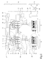
- FIG. 1 shows a control device according to the invention for controlling a melt-spinning machine.
- a plurality of different working materials for a material flow are arranged one after the other within the melt spinning machine in order to produce a plurality of synthetic threads in a plurality of steps from a polymer, for example in the form of a granulate.
- a polymer for example in the form of a granulate.
- the predetermined in the form of a granulate polymer material is melted into a polymer melt and over several Melting lines 4 to several spinning beams 5 distributed.
- spinning beams 5 For reasons of clarity, only two spinning beams 5 are shown here. As a rule, several spinning beams 5 will be used.
- the polymer melt is first fed to a melt metering pump 6, which meters the melt and distributes it via several distributor lines 8 to a plurality of spin packages 9.
- These spin packs 9 contain nozzle plates with a plurality of nozzle bores from which a plurality of filaments are extruded, which emerge as a filament bundle 10 and are combined into a respective thread 13.
- a preparation is applied by means of a preparation device 11.
- the preparation devices 11 are supplied with the preparation medium by a common preparation pump 12 via the illustrated connection lines.
- the threads 13 are guided in the form of a group of yarns over two driven godets 14 and then fed to a winding head 15, where the threads 13 are wound in several winding positions parallel to several coils 17.
- the winding head 15 a plurality of drives 16, wherein only three motors are exemplarily and representative of all drives, actuators and sensors shown.
- the melt spinning machine is divided both vertically and horizontally into several units.
- a working field 18 is defined in the vertical direction of each winding head 15 and the working means arranged above, which are arranged upstream in the process chain of the thread production.
- Such a working field 18 could be regarded as the smallest functional unit of the melt spinning machine, even if, as shown here, several working fields 18 share a common extruder 1.
- a group of threads 13 is produced as a group of threads and wound together to form coils 17.
- two adjacent working fields 18 are shown. In practice Such melt spinning machines on a plurality of such work fields 18.
- the working fields 18 are subdivided into different workstations 19 which contain one or more working means for carrying out one or more work steps in the process chain.
- a top workstation 19 include the extruder 1
- an underlying middle workstation 19 includes the godets 14
- a bottom workstation 19 includes the winding head 15.
- the boundaries between the workstations 19 are not defined according to the invention.
- the boundary between the lowest and the middle workstation 19 can be set differently depending on the general conditions, that is, certain work equipment could be assigned to both the lowest and the middle workstation.
- the workstations 19 associated work equipment in groups to a take-up device 25, a thread treatment device 26 and a spinning device 27 are summarized.
- the upper workstation 19 contains the working means of the spinning device 27, the middle workstation 19 the working means of the thread treating device 26 and the lower workstation 19 the working means of the winding device 25.
- the control device of in FIG. 1 illustrated melt spinning machine is divided into a plurality of control units 20, 30 and 40, which are assigned to the individual workstations 19.
- the control unit 40 is assigned to the working means of the spinning device 27.
- the working means of the thread treating device 26 is controlled via the control unit 30 and the working means of the winding device 25 via the control unit 20.
- the spinning device 27 associated control unit 40 is connected via a plurality of control lines 41 and 42 with the extruder drive 2 and the extruder heater 3 and via a plurality of control line 43 with the Schmelzedosierpumpenantrieben 7 and controls them. Furthermore, the control unit 40 is connected via control lines, not shown here, with sensors which serve, for example, to detect the melt pressure, the melt temperature or the temperature of the spinneret 5. The control unit 40 is also connected via the control lines 43 with working means of the workstation of the adjacent working field 18. Thus, the Schmelzedosierpumpenantriebe 7 of the adjacent working field 18 are also assigned to the control unit 40. The spinning device 27 of the adjacent working field 18 is connected to the central extruder 1.
- the central workstation depending on a working field 18 associated control unit 30, which is associated with the thread treatment device 26 is connected via a plurality of control lines 31 to the drive units of the godets 14 and a control line 32 to the drive units of the preparation pump 12.
- a working field 18 associated control unit 30 which is associated with the thread treatment device 26 is connected via a plurality of control lines 31 to the drive units of the godets 14 and a control line 32 to the drive units of the preparation pump 12.
- ancillaries and sensors which are associated with the thread treatment device 26.
- the controller 30 is shown here only for a working field 18. According to the invention, each working area 18 has its own control unit 30.
- the lower workstation associated control unit 20 controls the drives and sensors of the winding device 25 via a control line 22 at.
- the winding device 25 has the winding head 15 in this embodiment.
- the controller is shown only for a working field 18 for reasons of clarity. According to the invention, each of the working fields 18 has its own control device 20.
- the first working field 18 associated with control units 20, 30 and 40 are connected to each other via a data line 24.
- the data line 24 could be designed, for example, as an Ethernet connection.
- the control units 20, 30 and 40 communicate with each other.
- the data line 24 will be a bus line or a network connection. But it is also possible to realize the connection by means of one or more analog lines.
- the control units 20, 30 and 40 are connected to an operating device 21 that is integrated into the data line 24. This is a manual control device or a process control system without any master function. This is used to receive setpoints or operating parameters.
- the controllers 20, 30 and 40 are equal in the control hierarchy and cooperate to control all work equipment of a working field. The coordination between the control units 20, 30 and 40 takes place exclusively via a constant exchange of data between the control units.
- another control unit 45 is connected to the control units 20, 30 and 40 in this embodiment.
- This has a means for providing updates 44, via which updates are transmitted to the control units 20, 30 and 40.
- the means for deploying updates is a disk or storage. This can be for example a USB stick or a CD-Rom. Alternatively, this can also be an area of the main memory of a computer in which the update was previously loaded.
- One of the operator panels 21 or 45 may be connected via a wide area network connection, for example via the Internet or via a modem connection. Thus, this operating device can be located for example in a service station of the manufacturer, which supports the user in this way.
- FIG. 2 is a further embodiment of the control device according to the invention for a variant of the melt spinning machine FIG. 1 shown.
- the embodiment is essentially made with the embodiment Fig. 1 identical, so here's just the differences too FIG. 1 described and otherwise reference is made to the above description.
- the thread treating device 26 of the middle workstation 19 is formed in a changed configuration within the working field 18.
- the thread treatment device 26 has here per field 18 more Galettenduos 23, which may also be heated beyond.
- Such thread treatment device 26 are used in particular for the production of highly drawn threads.
- the multiplicity of drives and heaters in the godets 23 requires a more complex control device 30, which is a multiple of the working means of the control unit 30 FIG. 1 must drive.
- the controller 30 is coupled via the data line 24 to the adjacent controllers 20 and 40 to control the manufacturing process in the work area.
- the data line 24 may be formed as a pure data line or as a control line with data exchange.
- control device According to the invention, the advantage of the control device according to the invention is clear. To equip a variety of different melt spinning machines with a control device this can be modularly assembled from a modular system.
- FIG. 3 represents a further embodiment of the control device according to the invention for a further variant of the melt spinning machine
- FIG. 1 In contrast to FIG. 1 has the take-up 25 here next to the winding head 15 and a plurality of godets 14, which are connected directly to the winding head 15 in the form of a common unit.
- the division of the control device changes in the form that the control of the godets 14 now rests on the control device 20 assigned to the take-up device 25.
- the control unit 20 is connected via the control lines 31 to the godet drives of the godets 14 and via the control lines 22 to the drives of the winding head 15.
- the adjacent control unit 30 is thus only with work equipment the yarn treatment device 27 connected above the winding head 15.
- the control of the melt metering pump drives 7 is now assigned to the control unit 30, so that the control unit 40 only cooperates with the extruder 1 of the spinning device 27.
- the middle control unit 30 is connected via the control line 33 to the melt metering pump drives 7.
- This example shows only one option for the configuration of the control device according to the invention. Basically, it is possible and useful, even a winding head with integrated godets with a control structure as in FIG. 1 or 2 shown to combine or the control units 30 and 40 in FIG. 3 to summarize to a common control unit.
- control units 30 and 40 it is also possible to combine the control units 30 and 40 to a control unit, so that the working field 18 could be broken down, for example, in two workstations.
- the first upper work station would contain the working means for extruding spinning and dissecting the strands, and the lower work station would have the work means for stripping, drawing and winding the strands. All working means of the working field would then be controlled by the interaction of two control units.
Landscapes
- Engineering & Computer Science (AREA)
- Mechanical Engineering (AREA)
- Textile Engineering (AREA)
- Quality & Reliability (AREA)
- Spinning Methods And Devices For Manufacturing Artificial Fibers (AREA)
Description
- Die Erfindung betrifft eine Steuereinrichtung zum Steuern einer Schmelzspinnmaschine gemäß Anspruch 1.
- Bei der Herstellung von synthetischen Fäden mittels einer Schmelzspinnmaschine wird zunächst eine von einer Schmelzequelle, beispielsweise einem Extruder, kommende Kunststoffschmelze mit Hilfe einer Pumpe unter Druck auf mehrere Spinndüsen mit einer Vielzahl von Düsenbohrungen verteilt und zu mehreren Filamentbündeln gesponnen. Die Filamentbündel werden nach Abkühlung jeweils zu einem Faden zusammengefasst und mittels einer Aufwickeleinrichtung abgezogen und zu einer Spule aufgewickelt. Je nach Art der gewünschten Fadenqualität wird vor dem Aufwickeln eine weitere Behandlung, beispielsweise durch eine oder mehrere Galetten einer Verstreckeinrichtung erfolgen. Dabei erfährt der Faden durch unterschiedliche Umfangsgeschwindigkeiten und Temperaturen der Galettenmäntel eine thermomechanische Behandlung. Weiterhin sind bei der Schmelzspinnmaschine neben den oben genannten Aggregaten Nebenaggregate vorgesehen, wie beispielsweise Mittel zum dosierten Auftragen von Präparation.
- Die Schmelzspinnmaschine ist aus mehreren parallel angeordneten gleichartigen Arbeitsfeldern aufgebaut, auf denen jeweils mehrere Fäden in Form einer Fadenschar bearbeitet werden. Dabei wird die Fadenschar innerhalb des Arbeitsfeldes durch mehrere Arbeitsstationen extrudiert, abgezogen, verstreckt und zu Spulen aufgewickelt.
- Die einzelnen Arbeitsstationen der Schmelzspinnmaschine beziehungsweise der Arbeitsfelder werden dabei mittels einer Steuereinrichtung koordiniert angesteuert. Eine gattungsgemäße Steuereinrichtung ist aus der Offenlegungsschrift
DE 100 39 093 A1 bekannt. Hier werden die jeweils einem Fadenlauf beziehungsweise einer Fadenschar zugeordneten Arbeitsstationen bzw. deren Aggregate durch ein diesem Arbeitsfeld zugeordnetes Steuergerät angesteuert. Ein übergeordnetes Steuersystem steuert und koordiniert wiederum die einzelnen Steuergeräte sowie Aggregate, die mehreren Arbeitsfeldern gemeinsam zugeordnet sind, wie dem Extruder, an. Hierbei kommt eine Vielzahl gleicher Steuergeräte zum Einsatz. - Ein Nachteil dieser Struktur ist, dass die Struktur der Steuerung relativ starr an die Struktur der Schmelzspinnmaschine angelehnt ist. Zudem muss ein übergeordnetes Steuergerät vorgehalten werden.
- Es ist daher Aufgabe der Erfindung, eine kostengünstige Steuereinrichtung für Schmelzspinnmaschinen bereit zu stellen, die dennoch leicht an unterschiedliche Konfigurationen der Schmelzspinnmaschine angepasst werden kann.
- Diese Aufgabe wird dadurch gelöst, dass mehrere Steuergeräte vorgesehen sind und dass jeweils eine der Arbeitsstationen eines der Arbeitsfelder jeweils einem der Steuergeräte zugeordnet ist, und dass die Steuergeräte über zumindest eine Datenleitung ohne übergeordnete Master-Steuerung unmittelbar miteinander verbunden sind.
- Weitere vorteilhafte Weiterbildungen der Erfindung sind durch die Merkmale und Merkmalskombinationen der jeweiligen Unteransprüche definiert.
- Die Erfindung verlässt das bekannte Konzept einer zentralen Steuereinrichtung für eine Schmelzspinnmaschine, bei welcher die innerhalb einer der Arbeitsfelder angeordneten Arbeitsmittel der Arbeitsstationen zu einer Steuereinheit zusammengeschlossen sind, und wählt ein sich an den gleichartigen Arbeitsstationen orientiertes Steuerungskonzept. Hierbei wird jedes Arbeitsfeld logisch in einzelne Arbeitsstationen unterteilt, jede der Arbeitsstationen des Arbeitsfeldes wird einzelnen Steuergeräten zugeordnet und die einzelnen Steuergeräte sind mittels einer Datenleitung direkt miteinander verbunden und kommunizieren direkt miteinander, wodurch die Koordination der Steuergeräte untereinander erfolgt. Damit wird eine übergeordnete Master-Steuerung entbehrlich. Durch den ständigen Datenaustausch ist sichergestellt, dass die innerhalb eines Arbeitsfeldes zusammenwirkenden Arbeitsstationen koordiniert zur Fadenherstellung betrieben werden können. Dabei wird die Datenleitung vorzugsweise als eine Ethernetverbindung ausgebildet, so dass ganze Datenpakete zwischen den Steuergeräten austauschbar sind. Die Datenleitung kann auch ein Bussystem oder eine direkte digitale bzw. analoge Verbindung sein.
- Durch die in der Schmelzspinnmaschine erfindungsgemäß vertikal ausgerichtet Steuerungsebenen können auch vorteilhaft einzelne Arbeitsstationen gleicher Art innerhalb der Arbeitsfelder unabhängig von benachbarten Arbeitsstationen schnell ausgetauscht werden. Die benachbarten Steuerungsebenen bleiben hiervon unberührt. Insbesondere für Schmelzspinnmaschinen bietet dieses Steuerungskonzept einen besonderen Vorteil, da je nach Fadentype unterschiedliche Arbeitsmittel in den Arbeitsstationen insbesondere in Fadenbehandlungsvorrichtung zum Einsatz kommen. So ist bekannt POY-, FDY-, BCF- oder IDY- Fäden mit verschiedenen Arbeitsmitteln in der Fadenbehandlung herzustellen.
- Gleichartige Arbeitsstationen benachbarter Arbeitsfelder lassen sich gemäß einer vorteilhaften Weiterbildung der Erfindung bevorzugt zu einem Steuerverbund zusammenfügen, so dass die Arbeitsstationen gemeinsam mit einem der Steuergeräte verbunden sind. Damit lässt sich der Steuerungsaufwand selbst für eine Vielzahl von Arbeitsfeldern mit mehreren Arbeitsstationen auf ein Minimum reduzieren. Dies hat insbesondere bei Arbeitsstationen mit geringer Zahl zu steuernder Aktoren und Sensoren einen vereinfachten Aufbau zur Folge und weist Kostenvorteile auf.
- Zur Herstellung synthetischer Fäden weisen die Arbeitsstationen als Arbeitsmittel zumindest eine Spinnvorrichtung, eine Fadenbehandlungsvorrichtung und eine Aufwickelvorrichtung auf, wobei eine steuerliche Trennung bevorzugt zwischen der Aufwicklung und Fadenbehandlung erfolgt.
- Dadurch wird ein Steuergerät für die Aufwickelvorrichtung eingesetzt. Ein weiteres Steuergerät ist somit der Fadenbehandlungsvorrichtung zugeordnet. Zusätzlich oder alternativ ist ein weiteres Steuergerät für die Spinnvorrichtung vorgesehen.
- Der Vorteil derartiger Schmelzspinnmaschinen liegt darin, dass eine Modularisierung der Steuergeräte dadurch wirkungsvoll unterstützt wird. Verschiedene Typen von Schmelzspinnmaschinen unterscheiden sich hauptsächlich in der Bestückung der Fadenbehandlungsvorrichtung. So weisen Schmelzspinnmaschinen für voll verstreckte Fäden eine höhere Anzahl von teilweise beheizten Galetten auf. Bei einer erfindungsgemäßen Steuereinrichtung wird ein Steuergerät für die jeweils gleichartigen Aufwickelvorrichtungen mehrerer Arbeitsfelder verwendet. Dieses Steuergerät ist bei den verschiedenen Schmelzspinnmaschinen-Typen gleich. Für die unterschiedlich bestückten Fadenbehandlungsvorrichtungen können zwei oder mehr verschiedene Steuergeräte vorgehalten werden, die abhängig von der Bestückung der Fadenbehandlungsvorrichtung zum Einsatz kommen. Diese Steuergeräte selbst sind aber relativ einfach aufgebaut, so dass die Modularisierung und die Vorhaltung verschiedener Varianten kostengünstig möglich sind. Insbesondere ist es durch diese Struktur einfacher möglich, eine strikte Trennung zwischen der Spinnvorrichtung einerseits und den beiden darunter angeordneten Fadenbehandlungs- und Aufwickelvorrichtungen andererseits vorzunehmen. Mit dieser Trennung ist es einfacher möglich, standardisierte Spinnvorrichtungen mit flexibel angepassten Fadenbehandlungs- und Aufwickelvorrichtungen zu kombinieren.
- Bei einer steuerlichen Trennung zwischen der Aufwickelvorrichtung und der Fadenbehandlungsvorrichtung weist die Aufwickelvorrichtung vorzugsweise ein Spulkopf mit mehreren Wickelstellen zum kontinuierlichen Aufwickeln der Fäden auf. Die Fadenbehandlungsvorrichtung enthält dabei vorzugsweise mehrere Galetten zum Verstrecken der Fäden.
- In einer anderen Ausführungsvariante enthält die Aufwickelvorrichtung einen Spulkopf sowie Galetten. Dies ist beispielsweise dann sinnvoll, wenn Spulkopf und Galetten in einer baulichen Einheit integriert sind, so dass beide Aggregate gemeinsam durch das zugeordnete Steuergerät steuerbar sind.
- Es besteht jedoch auch die Möglichkeit, dem Steuergerät, das der Aufwickelvorrichtung zugeordnet ist, zusätzliche Aggregate aus der Fadenbehandlungsvorrichtung zuzuordnen. Somit lässt sich das Zusammenwirken zwischen Spulkopf und Galetten bei der Fadenherstellung bei bestimmten Prozessen noch optimieren.
- Grundsätzlich wäre es jedoch auch möglich, die Steuergeräte für die Aufwickelvorrichtung und die Fadenbehandlungsvorrichtung durch ein gemeinsames Steuergerät zu bilden. Dies ist insbesondere dann vorteilhaft, wenn beispielsweise die Fadenbehandlungsvorrichtung wenige Aggregate aufweist.
- In einer Weiterbildung der Erfindung sind die Steuergeräte mit einer Bedieneinheit verbunden, die jedoch nicht die Aufgaben eines Master-Steuergerätes erfüllt. Damit lässt sich der Zugriff auf die gleichberechtigten Steuergeräte für eine Bedienperson verbessern, so dass beispielsweise Vorgaben zur Veränderungen von Prozessparametern in den Arbeitsstationen über die Bedieneinheit dem jeweilig zugeordneten Steuergerät erfolgen können.
- In einer bevorzugten Weiterbildung stellt diese Bedieneinheit Software-Updates für die Steuergeräte bereit. Dies erfolgt durch ein geeignetes Mittel, beispielsweise durch einen Speicher oder einen anderem Datenträger.
- Diese Bedieneinheit oder alternativ eine weitere Bedieneinheit kann über ein Wide Area Network, beispielsweise über das Internet oder über eine Modem-Verbindung verbunden sein. Dadurch kann über eine räumliche Distanz Hilfestellung, Fehlerdiagnose oder ein Software-Update zur Verfügung gestellt werden.
- Ein Ausführungsbeispiel der erfindungsgemäßen Steuereinrichtung für eine Schmelzspinnmaschine wird im Folgenden unter Hinweis auf die beigefügten Zeichnungen näher beschrieben.
- Es stellen dar:
-
Fig. 1 : Eine erfindungsgemäße Steuereinrichtung zum Steuern einer Schmelzspinnmaschine, -
Fig. 2 eine erfindungsgemäße Steuereinrichtung zum Steuern einer Variante der Schmelzspinnmaschine, -
Fig. 3 eine erfindungsgemäße Steuereinrichtung zum Steuern einer weiteren Variante der Schmelzspinnmaschine, -
Figur 1 zeigt eine erfindungsgemäße Steuereinrichtung zum Steuern einer Schmelzspinnmaschine. - Zur Herstellung einer Vielzahl synthetischer Fäden ist innerhalb der Schmelzspinnmaschine eine Mehrzahl verschiedener Arbeitsmittel zu einem Materialfluss nacheinander angeordnet, um in mehreren Arbeitsschritten aus einem Polymer beispielsweise in Form eines Granulats eine Mehrzahl synthetischer Fäden herzustellen. Bei dem gezeigten Ausführungsbeispiel der Schmelzspinnmaschine beginnt die Kette der Arbeitsmittel mit einem Extruder 1.Von dem Extruder 1, der über einen Extruderantrieb 2 angetrieben und mittels einer Extruderheizung 3 beheizt ist, wird das in Form eines Granulats vorgegeben Polymermaterial zu einer Polymerschmelze aufgeschmolzen und über mehrere Schmelzeleitungen 4 zu mehreren Spinnbalken 5 verteilt. Aus Gründen der Übersichtlichkeit sind hier nur zwei Spinnbalken 5 dargestellt. In der Regel werden mehrere Spinnbalken 5 zum Einsatz kommen. Ebenso ist es möglich, mehrere Extruder 1 oder alternativ eine Polymerisationsanlage zur Bereitstellung einer Polymerschmelze zu verwenden.
- Innerhalb des Spinnbalkens 5 wird die Polymerschmelze zunächst einer Schmelzedosierpumpe 6 zugeführt, die die Schmelze dosiert und über mehrere Verteilerleitungen 8 auf mehrere Spinnpakete 9 verteilt. Diese Spinnpakete 9 enthalten Düsenplatten mit einer Vielzahl von Düsenbohrungen, aus denen eine Vielzahl von Filamenten extrudiert werden, welche als ein Filamentbündel 10 austreten und zu jeweils einen Faden 13 zusammengefasst werden. Üblicherweise wird an dem Punkt, an dem die Filamentbündel 9 zu Fäden 13 zusammengefasst werden, mittels einer Präparationseinrichtung 11 eine Präparation aufgetragen. Die Präparationseinrichtungen 11 werden durch eine gemeinsame Präparationspumpe 12 über die dargestellten Verbindungsleitungen mit dem Präparationsmittel versorgt.
- Anschließend werden die Fäden 13 in Form einer Fadenschar über zwei angetriebene Galetten 14 geführt und anschließend einem Spulkopf 15 zugeführt, wo die Fäden 13 in mehreren Wickelstellen parallel zu mehreren Spulen 17 aufgewickelt werden. Hierzu weist der Spulkopf 15 mehrere Antriebe 16 auf, wobei hier exemplarisch und stellvertretend für alle Antriebe, Aktoren und Sensoren nur drei Motoren dargestellt sind.
- Zur Steuerung alle Arbeitsmittel ist die Schmelzspinnmaschine sowohl vertikal als auch horizontal in mehrere Einheiten gegliedert. Zunächst wird in vertikaler Richtung von jedem Spulkopf 15 und den darüber angeordneten Arbeitsmittel, die in der Prozesskette der Fadenherstellung vorgeordnet sind, ein Arbeitsfeld 18 definiert. Ein solches Arbeitsfeld 18 könnte als kleinste für sich funktionsfähige Einheit der Schmelzspinnmaschine angesehen werden, auch wenn wie hier dargestellt sich mehrere Arbeitsfelder 18 einen gemeinsamen Extruder 1 teilen. In dem Arbeitsfeld 18 wird eine Gruppe von Fäden 13 als Fadenschar hergestellt und gemeinsam zu Spulen 17 aufgewickelt. In dem gezeigten Ausführungsbeispiel sind zwei benachbarte Arbeitsfelder 18 gezeigt. In Praxis weisen derartige Schmelzspinnmaschinen eine Mehrzahl derartiger Arbeitsfelder 18 auf.
- In horizontaler Richtung unterteilen sich die Arbeitsfelder 18 in verschiedene Arbeitsstationen 19, die ein oder mehrere Arbeitsmittel zur Durchführung eines oder mehrerer Arbeitsschritte in der Prozesskette enthalten. So können beispielsweise, wie in
Figur 1 dargestellt, eine oberste Arbeitsstation 19 den Extruder 1 beinhalten, eine darunter angesiedelte mittlere Arbeitsstation 19 beinhaltet die Galetten 14 und eine unten angesiedelte Arbeitsstation 19 beinhaltet den Spulkopf 15. Dabei sind die Grenzen zwischen den Arbeitsstationen 19 erfindungsgemäß nicht festgelegt. Insbesondere die Grenze zwischen der untersten und der mittleren Arbeitsstation 19 kann abhängig von den Rahmenbedingungen unterschiedlich festgelegt werden, das heißt bestimmte Arbeitsmittel könnten sowohl der untersten als auch der mittleren Arbeitsstation zugeordnet werden. - In dem in
Figur 1 dargestellten Ausführungsbeispiel sind die den Arbeitsstationen 19 zugeordneten Arbeitsmitteln in Gruppen zu einer Aufwickelvorrichtung 25, einer Fadenbehandlungsvorrichtung 26 und einer Spinnvorrichtung 27 zusammengefasst. Insoweit enthält die obere Arbeitsstation 19 die Arbeitsmittel der Spinnvorrichtung 27, die mittlere Arbeitsstation 19 die Arbeitsmittel der Fadenbehandlungsvorrichtung 26 und die untere Arbeitsstation 19 die Arbeitsmittel der Aufwickelvorrichtung 25. - Die Steuereinrichtung der in
Figur 1 dargestellten Schmelzspinnmaschine unterteilt sich in mehrere Steuergeräte 20, 30 und 40, die den einzelnen Arbeitsstationen 19 zugeordnet sind. So ist das Steuergerät 40 den Arbeitsmitteln der Spinnvorrichtung 27 zugeordnet. Die Arbeitsmittel der Fadenbehandlungsvorrichtung 26 wird über das Steuergerät 30 und die Arbeitsmittel der Aufwickelvorrichtung 25 über das Steuergerät 20 gesteuert. - Das der Spinnvorrichtung 27 zugeordnete Steuergerät 40 ist über mehrere Steuerleitungen 41 und 42 mit dem Extruderantrieb 2 und der Extruderheizung 3 sowie über mehrere Steuerleitung 43 mit den Schmelzedosierpumpenantrieben 7 verbunden und steuert diese an. Weiterhin ist das Steuergerät 40 über hier nicht dargestellte Steuerleitungen mit Sensoren verbundenen, die beispielsweise der Erfassung des Schmelzedrucks, der Schmelzetemperatur oder der Temperatur des Spinnbalkens 5 dienen. Das Steuergerät 40 ist über die Steuerleitungen 43 auch mit Arbeitsmitteln der Arbeitsstation des benachbarten Arbeitsfeldes 18 verbunden. So sind die Schmelzedosierpumpenantriebe 7 des benachbarten Arbeitsfeldes 18 ebenfalls dem Steuergerät 40 zugeordnet. Die Spinnvorrichtung 27 des benachbarten Arbeitsfeldes 18 ist dabei an dem zentralen Extruder 1 angeschlossen.
- Das der mittleren Arbeitsstation je einem Arbeitsfeld 18 zugeordnete Steuergerät 30, das der Fadenbehandlungsvorrichtung 26 zugeordnet ist, ist über mehrere Steuerleitungen 31 mit den Antriebseinheiten der Galetten 14 sowie über eine Steuerleitung 32 mit den Antriebseinheiten der Präparationspumpe 12 verbunden. Aus Übersichtsgründen nicht dargestellt, aber erfindungsgemäß enthalten sind hier nicht dargestellte Nebenaggregate und Sensoren, die der Fadenbehandlungsvorrichtung 26 zuzuordnen sind. Ebenfalls aus Gründen der Übersichtlichkeit ist das Steuergerät 30 hier nur für ein Arbeitsfeld 18 dargestellt. Erfindungsgemäß verfügt jedes Arbeitsfeld 18 über ein eigenes Steuergerät 30.
- Das der unteren Arbeitsstation zugeordnete Steuergerät 20 steuert die Antriebe und Sensoren der Aufwickelvorrichtung 25 über eine Steuerleitung 22 an. Die Aufwickelvorrichtung 25 weist in diesem Ausführungsbeispiel den Spulkopf 15 auf. Auch hier ist aus Gründen der Übersichtlichkeit das Steuergerät nur für ein Arbeitsfeld 18 dargestellt. Erfindungsgemäß verfügt jedes der Arbeitsfelder 18 über ein eigenes Steuergerät 20.
- Die dem ersten Arbeitsfeld 18 zugeordneten Steuergeräte 20, 30 und 40 sind über eine Datenleitung 24 miteinander verbunden. Die Datenleitung 24 könnte beispielsweise als eine Ethernetverbindung ausgebildet sein. Über die Datenleitung 24 kommunizieren die Steuergeräte 20, 30 und 40 miteinander. In der Regel wird die Datenleitung 24 eine Bus-Leitung oder eine Netzwerkverbindung sein. Es ist aber auch möglich, die Verbindung mittels einer oder mehrerer analoger Leitungen zu realisieren. Darüber hinaus sind die Steuergeräte 20, 30 und 40 mit einem Bediengerät 21 verbunden, dass in die Datenleitung 24 mit eingebunden ist. Dabei handelt es sich um ein Hand-Bediengerät oder um ein Prozess-Leitsystem ohne jegliche Masterfunktion. Hierüber werden Sollwerte oder Betriebsparameter entgegengenommen. Die Steuergeräte 20, 30 und 40 sind gleichrangig in der Steuerhierarchie und wirken zur Steuerung aller Arbeitsmittel eines Arbeitsfeldes zusammen. Die Koordination zwischen den Steuergeräten 20,30 und 40 erfolgt ausschließlich über einen ständigen Datenaustausch zwischen den Steuergeräten.
- Parallel ist in diesem Ausführungsbeispiel ein weiteres Bediengerät 45 mit den Steuergeräten 20, 30 und 40 verbunden. Dieses weist ein Mittel zum Bereitstellen von Updates 44 auf, über welches Updates an die Steuergeräte 20, 30 und 40 übertragen werden. Bei dem Mittel zum Bereitstellen von Updates handelt es sich um einen Datenträger oder Speicher. Dies kann beispielsweise ein USB-Stick oder eine CD-Rom sein. Alternativ kann dies auch ein Bereich des Arbeitsspeichers eines Computers sein, in den zuvor das Update geladen wurde. Eines der Bediengeräte 21 oder 45 kann über eine Wide Area Network-Verbindung angeschlossen sein, beispielsweise über das Internet oder über eine Modemverbindung. Somit kann sich dieses Bediengerät beispielsweise in einer Servicestation des Herstellers befinden, der dem Anwender auf diese Weise unterstützt.
- In
Figur 2 ist ein weiteres Ausführungsbeispiel der erfindungsgemäßen Steuereinrichtung für eine Variante der Schmelzspinnmaschine ausFigur 1 dargestellt. Das Ausführungsbeispiel ist im wesentlich mit dem Ausführungsbeispiel ausFig. 1 identisch, so dass hier nur die Unterschiede zuFigur 1 beschrieben werden und ansonsten Bezug zu der vorgenannten Beschreibung genommen wird. - Bei dem in
Fig. 2 gezeigten Ausführungsbeispiel ist die Fadenbehandlungsvorrichtung 26 der mittleren Arbeitsstation 19 in einer geänderten Konfiguration innerhalb des Arbeitsfeldes 18 ausgebildet. Die Fadenbehandlungsvorrichtung 26 weist hier pro Arbeitsfeld 18 mehrere Galettenduos 23 auf, die darüber hinaus auch beheizt sein können. Derartige Fadenbehandlungsvorrichtung 26 werden insbesondere zur Herstellung von hochverstreckten Fäden eingesetzt. Die Vielzahl von Antrieben und Heizungen in den Galettenduos 23 erfordert ein komplexeres Steuergerät 30, das ein Vielfaches der Arbeitsmittel des Steuergerätes 30 ausFigur 1 ansteuern muss. Das Steuergerät 30 ist über die Datenleitung 24 mit den benachbarten Steuergeräten 20 und 40 gekoppelt, um den Herstellungsprozess in dem Arbeitsfeld zu steuern. Die Datenleitung 24 kann als reine Datenleitung oder auch als Steuerleitung mit Datenaustausch ausgebildet sein. - Hier wird auch der Vorteil der erfindungsgemäßen Steuereinrichtung deutlich. Um eine Vielzahl von unterschiedlichen Schmelzspinnmaschinen mit einer Steuereinrichtung auszurüsten kann diese modular aus einem Baukastensystem zusammengestellt werden.
-
Figur 3 stellt ein weiteres Ausführungsbeispiel der erfindungsgemäßen Steuereinrichtung für eine weitere Variante der Schmelzspinnmaschine ausFigur 1 dar. Im Unterschied zuFigur 1 weist die Aufwickelvorrichtung 25 hier neben dem Spulkopf 15 auch mehrere Galetten 14 auf, die direkt mit dem Spulkopf 15 in Form einer gemeinsamen Baueinheit verbunden sind. Dadurch ändert sich die Aufteilung der Steuereinrichtung in der Form, dass die Steuerung der Galetten14 nun dem der Aufwickelvorrichtung 25 zugeordneten Steuergerät 20 obliegt. Das Steuergerät 20 ist über die Steuerleitungen 31 mit den Galettenantrieben der Galetten 14 und über die Steuerleitungen 22 mit den Antrieben des Spulkopf 15 verbunden. Das benachbarte Steuergerät 30 ist somit nur noch mit Arbeitsmitteln der Fadenbehandlungsvorrichtung 27 oberhalb des Spulkopfes 15 verbunden. Zusätzlich wird daher hier nun die Steuerung der Schmelzedosierpumpenantriebe 7 dem Steuergerät 30 zugeordnet, so dass das Steuergerät 40 nur noch mit dem Extruder 1 der Spinnvorrichtung 27 zusammenwirkt. Das mittlere Steuergerät 30 ist hierzu über die Steuerleitung 33 mit den Schmelzedosierpumpenantrieben 7 verbunden. Dieses Beispiel zeigt lediglich eine Option für die Konfiguration der erfindungsgemäßen Steuereinrichtung. Grundsätzlich ist es möglich und sinnvoll, auch einen Spulkopf mit integrierten Galetten mit einer Steuerungsstruktur wie inFigur 1 oder2 gezeigt zu kombinieren oder aber die Steuergeräte 30 und 40 inFigur 3 zu einem gemeinsamen Steuergerät zusammenzufassen. - Bei dem in
Figur 3 dargestellten Ausführungsbeispiel besteht alternativ auch die Möglichkeit die Steuergerate 30 und 40 zu einem Steuergerät zu kombinieren, so dass das Arbeitsfeld 18 beispielsweise in zwei Arbeitsstationen aufgegliedert werden könnte. Die erste obere Arbeitsstation würde die Arbeitsmittel zum Extrudieren Spinnen und Präparieren der Fäden enthalten und die untere Arbeitsstation weist die Arbeitsmittel zum Abziehen, Verstrecken und Aufwickeln der Fäden auf. Alle Arbeitsmittel des Arbeitsfeldes würden dann durch das Zusammenwirken zweier Steuergeräte gesteuert. -
- 1
- Extruder
- 2
- Extruderantrieb
- 3
- Extruderheizung
- 4
- Schmelzeleitung
- 5
- Spinnbalken
- 6
- Schmelzedosierpumpe
- 7
- Schmelzedosierpumpenantrieb
- 8
- Verteilerleitung
- 9
- Spinnpaket
- 10
- Filamentbündel
- 11
- Präparationseinrichtung
- 12
- Präparationspumpe
- 13
- Faden
- 14
- Galetten
- 15
- Spulkopf
- 16
- Antrieb
- 17
- Spulen
- 18
- Arbeitsfeld
- 19
- Arbeitsstation
- 20
- Steuergerät
- 21
- Bediengerät
- 22
- Steuerleitung
- 23
- Galettenduo
- 24
- Datenleitung
- 25
- Aufwickelvorrichtung
- 26
- Fadenbehandlungsvorrichtung
- 27
- Spinnvorrichtung
- 30
- Steuergerät
- 31 - 33
- Steuerleitung
- 40
- Steuergerät
- 41 - 43
- Steuerleitung
- 44
- Mittel zum Bereitstellen von Updates
- 45
- Bediengerät
Claims (9)
- Steuereinrichtung zum Steuern einer Schmelzspinnmaschine, welche mehrere gleichartige Arbeitsfelder (18) zum Herstellen mehrerer Fäden (13) pro Arbeitsfeld aufweist,
wobei jedes der Arbeitsfelder (18) mehrere Arbeitsstationen (19) mit zumindest einem Arbeitsmittel (27, 26, 25) zum Durchführen zumindest eines dieser Arbeitsstation zugeordneten Arbeitsschrittes aufweist, wobei
mehrere Steuergeräte (20, 30, 40) vorgesehen sind und wobei jeweils eine der Arbeitsstationen (19) eines der Arbeitsfelder (18) jeweils einem der Steuergeräte (20, 30, 40) zugeordnet ist, dadurch gekennzeichnet, dass die Steuergeräte (20, 30, 40) zum Datenaustausch über zumindest eine Datenleitung (24) ohne übergeordnete Master-Steuerung unmittelbar miteinander verbunden sind. - Steuereinrichtung nach Anspruch 1,
dadurch gekennzeichnet, dass
zumindest eines der Steuergeräte (20, 30, 40) mehreren gleichartigen Arbeitsstationen (19) mehrerer Arbeitsfelder (18) zugeordnet ist. - Steuereinrichtung nach Anspruch 1 oder 2,
dadurch gekennzeichnet, dass
eine der Arbeitsstationen (19) der Schmelzspinnmaschine als Arbeitsmittel eine Aufwickelvorrichtung (25) aufweist, die mit einem zugeordnetem Steuergerät (20) verbunden ist, und dass weitere Arbeitsstationen (19) der Schmelzspinnmaschine als Arbeitsmittel eine Fadenbehandlungsvorrichtung (26) und/oder eine Spinnvorrichtung (27) aufweisen, die separat mit zugeordneten benachbarten Steuergeräten (30, 40) verbunden sind. - Steuereinrichtung nach Anspruch 3,
dadurch gekennzeichnet, dass
mehreren Spinnvorrichtungen (27) gemeinsam dem betreffenden Steuergerät (40) der Arbeitsstation (19) zugeordnet sind. - Steuereinrichtung nach einem der Ansprüche 1 bis 4,
dadurch gekennzeichnet, dass
die Aufwickelvorrichtung (25) einen Spulkopf (15) und dass die Fadenbehandlungseinrichtung (26) mehrere Galetten (14) enthält, welche separat durch mehrere der Steuergeräte (20,30) oder gemeinsam durch eines der Steuergeräte (20) steuerbar sind. - Steuereinrichtung nach einem der Ansprüche 1 bis 4,
dadurch gekennzeichnet, dass
die Aufwickelvorrichtung (25) einen Spulkopf (15) und mehrere Galetten (14) enthält, welche gemeinsam durch eines der Steuergeräte (20) steuerbar sind. - Steuereinrichtung nach einem der vorhergehenden Ansprüche,
dadurch gekennzeichnet, dass
das der Aufwickelvorrichtung (25) zugeordnete Steuergerät (20) sowie das der Fadenbehandlungsvorrichtung (26) zugeordnete Steuergerät (30) und/oder das der Spinnvorrichtung (27) zugeordnete Steuergerät (40) mit einer Bedieneinheit (21) verbunden sind. - Steuereinrichtung nach Anspruch 7,
dadurch gekennzeichnet, dass
die Bedieneinheit (21) ein Mittel (44) zum Bereitstellen von Updates aufweist. - Steuereinrichtung nach Anspruch 7 oder 8,
dadurch gekennzeichnet, dass
die Bedieneinheit (21) oder eine zweite Bedieneinheit über ein Wide Area Network, vorzugsweise über das Internet angebunden ist.
Applications Claiming Priority (3)
| Application Number | Priority Date | Filing Date | Title |
|---|---|---|---|
| DE102009057941 | 2009-12-11 | ||
| DE102010013408 | 2010-03-30 | ||
| PCT/EP2010/068847 WO2011069911A1 (de) | 2009-12-11 | 2010-12-03 | Steuereinrichtung |
Publications (2)
| Publication Number | Publication Date |
|---|---|
| EP2510139A1 EP2510139A1 (de) | 2012-10-17 |
| EP2510139B1 true EP2510139B1 (de) | 2014-02-19 |
Family
ID=43708821
Family Applications (1)
| Application Number | Title | Priority Date | Filing Date |
|---|---|---|---|
| EP10785429.1A Not-in-force EP2510139B1 (de) | 2009-12-11 | 2010-12-03 | Steuereinrichtung zum steuern einer schmelzspinnmaschine |
Country Status (4)
| Country | Link |
|---|---|
| EP (1) | EP2510139B1 (de) |
| JP (1) | JP5717755B2 (de) |
| CN (1) | CN102652190B (de) |
| WO (1) | WO2011069911A1 (de) |
Families Citing this family (4)
| Publication number | Priority date | Publication date | Assignee | Title |
|---|---|---|---|---|
| CN103361751A (zh) * | 2012-04-06 | 2013-10-23 | 欧瑞康纺织技术(北京)有限公司 | 纺丝机 |
| DE102014017054A1 (de) | 2014-11-18 | 2016-05-19 | Oerlikon Textile Gmbh & Co. Kg | Schmelzspinnvorrichtung |
| DE102015012214A1 (de) * | 2015-09-17 | 2017-03-23 | Saurer Germany Gmbh & Co. Kg | Verfahren zum Anpassen einer eine Garnpartieherstellung betreffenden werksseitigen Auslegung einer Offenend-Rotorspinnmaschine |
| DE102017010473A1 (de) * | 2017-11-10 | 2019-05-16 | Oerlikon Textile Gmbh & Co. Kg | Maschinenanlage zur Herstellung oder Behandlung synthetischer Fäden |
Family Cites Families (12)
| Publication number | Priority date | Publication date | Assignee | Title |
|---|---|---|---|---|
| JPS6199439A (ja) * | 1984-09-29 | 1986-05-17 | Fujitsu Ltd | グル−プアドレス通信方式 |
| JPH01183236A (ja) * | 1988-01-18 | 1989-07-21 | Nec Corp | マルチプロセツサシステムの通信制御方式 |
| CN1056554C (zh) * | 1995-09-28 | 2000-09-20 | 纳幕尔杜邦公司 | 制造着色挤出制品的方法 |
| DE10039093A1 (de) | 1999-08-13 | 2001-03-29 | Barmag Barmer Maschf | Steuereinrichtung |
| KR100423879B1 (ko) * | 2000-04-07 | 2004-03-22 | (주)세미콘사이버 | 인터넷을 이용한 생산설비의 상태정보 엑세스 방법과 그시스템 |
| DE10153457B4 (de) * | 2001-10-30 | 2015-07-16 | Rieter Ingolstadt Gmbh | Textilmaschine mit einer Vielzahl von Bearbeitungsstellen und Kommunikationsverfahren hierfür |
| EP1563128A1 (de) * | 2002-11-23 | 2005-08-17 | Saurer GmbH & Co. KG | Vorrichtung zum schmelzspinnen und aufwickeln mehrerer fäden |
| JP4903158B2 (ja) * | 2004-12-22 | 2012-03-28 | ザウラー ゲゼルシャフト ミット ベシュレンクテル ハフツング ウント コンパニー コマンディートゲゼルシャフト | 多数本のマルチフィラメント糸を溶融紡績しかつテクスチャード加工する方法と装置 |
| DE102005003089A1 (de) * | 2005-01-22 | 2006-07-27 | Saurer Gmbh & Co. Kg | Verfahren und Vorrichtung zum Stauchkräuseln eines multifilen Fadens |
| DE102005037178A1 (de) * | 2005-08-06 | 2007-02-08 | Saurer Gmbh & Co. Kg | Vorrichtung zum Schmelzspinnen und Aufwickeln einer Vielzahl von Fäden sowie ein Verfahren zum Betreiben einer derartigen Vorrichtung |
| EP1924726A1 (de) * | 2005-08-17 | 2008-05-28 | Oerlikon Textile GmbH & Co. KG | Verfahren und vorrichtung zum aufwickeln einer vielzahl synthetischer fäden |
| WO2007128498A1 (de) * | 2006-05-08 | 2007-11-15 | Oerlikon Textile Gmbh & Co. Kg | Vorrichtung zum schmelzspinnen, behandeln und aufwickeln, von synthetischen fäden |
-
2010
- 2010-12-03 EP EP10785429.1A patent/EP2510139B1/de not_active Not-in-force
- 2010-12-03 CN CN201080055970.1A patent/CN102652190B/zh active Active
- 2010-12-03 JP JP2012542470A patent/JP5717755B2/ja active Active
- 2010-12-03 WO PCT/EP2010/068847 patent/WO2011069911A1/de active Application Filing
Also Published As
| Publication number | Publication date |
|---|---|
| WO2011069911A1 (de) | 2011-06-16 |
| EP2510139A1 (de) | 2012-10-17 |
| JP5717755B2 (ja) | 2015-05-13 |
| CN102652190A (zh) | 2012-08-29 |
| JP2013513733A (ja) | 2013-04-22 |
| CN102652190B (zh) | 2014-08-20 |
Similar Documents
| Publication | Publication Date | Title |
|---|---|---|
| EP2016212B1 (de) | Spinn-treck-texturiermaschine | |
| EP2016211B1 (de) | Vorrichtung zum schmelzspinnen, behandeln und aufwickeln, von synthetischen fäden | |
| EP1527217B1 (de) | Vorrichtung zum spinnen und aufwickeln | |
| EP2558626B1 (de) | Vorrichtung zum abziehen und aufwickeln synthetischer fäden | |
| EP2510139B1 (de) | Steuereinrichtung zum steuern einer schmelzspinnmaschine | |
| EP0957187A2 (de) | Vorrichtung und Verfahren zur Herstellung von Mikrofilamenten von hoher Titer-Gleichmässigkeit aus thermoplastischen Polymeren | |
| EP1778899A1 (de) | Vorrichtung und verfahren zum schmelzspinnen, abziehen, behandeln und aufwickeln mehrerer synthetischer fäden | |
| DE10045473A1 (de) | Spinnvorrichtung | |
| DE102017110572A1 (de) | Verfahren zur Überwachung und Bedienung einer Mehrzahl von Schmelzspinnstellen sowie eine Schmelzspinnanlage mit mehreren Schmelzspinnstellen | |
| EP2737115B1 (de) | Schmelzspinnvorrichtung | |
| WO2012113668A1 (de) | Vorrichtung zum schmelzspinnen | |
| EP0541552B1 (de) | Verfahren und spinnvorrichtung zur herstellung von mikrofilamenten | |
| WO2001092615A2 (de) | Verfahren zur steuerung einer texturiermaschine sowie eine texturiermaschine | |
| DE102005037178A1 (de) | Vorrichtung zum Schmelzspinnen und Aufwickeln einer Vielzahl von Fäden sowie ein Verfahren zum Betreiben einer derartigen Vorrichtung | |
| EP3047056B1 (de) | Vorrichtung zur herstellung mehrfarbiger gekräuselter verbundfäden | |
| EP1735484B1 (de) | Verfahren und vorrichtung zum schmelzspinnen mehrerer multifiler fäden | |
| EP1838908B1 (de) | Verfahren und vorrichtung zum schmelzspinnen und texturieren einer vielzahl von multifilen faeden | |
| DE10355294A1 (de) | Spinnanlage | |
| EP1687464B1 (de) | Spinnanlage | |
| WO2004088008A1 (de) | Verfahren und vorrichtung zur herstellung von bcf-fäden | |
| DE4404258A1 (de) | Anblaseinrichtung in einer Spinnanlage für thermoplastische Fäden | |
| DE112011101081T5 (de) | Mehrfachfaser-Spinnvorrichtung und Verfahren zu deren Regelung | |
| DE102017000607A1 (de) | Vorrichtung zum Abziehen, Verstrecken und Aufwickeln einer synthetischen Fadenschar | |
| WO2022167427A1 (de) | Verfahren zum schmelzspinnen, verstrecken und relaxieren von synthetischen fäden sowie vorrichtung zur durchführung des verfahrens | |
| WO2016139207A1 (de) | Maschinenanlage zur herstellung oder behandlung von synthetischen fäden |
Legal Events
| Date | Code | Title | Description |
|---|---|---|---|
| PUAI | Public reference made under article 153(3) epc to a published international application that has entered the european phase |
Free format text: ORIGINAL CODE: 0009012 |
|
| 17P | Request for examination filed |
Effective date: 20120426 |
|
| AK | Designated contracting states |
Kind code of ref document: A1 Designated state(s): AL AT BE BG CH CY CZ DE DK EE ES FI FR GB GR HR HU IE IS IT LI LT LU LV MC MK MT NL NO PL PT RO RS SE SI SK SM TR |
|
| DAX | Request for extension of the european patent (deleted) | ||
| GRAP | Despatch of communication of intention to grant a patent |
Free format text: ORIGINAL CODE: EPIDOSNIGR1 |
|
| INTG | Intention to grant announced |
Effective date: 20130927 |
|
| GRAS | Grant fee paid |
Free format text: ORIGINAL CODE: EPIDOSNIGR3 |
|
| GRAA | (expected) grant |
Free format text: ORIGINAL CODE: 0009210 |
|
| AK | Designated contracting states |
Kind code of ref document: B1 Designated state(s): AL AT BE BG CH CY CZ DE DK EE ES FI FR GB GR HR HU IE IS IT LI LT LU LV MC MK MT NL NO PL PT RO RS SE SI SK SM TR |
|
| REG | Reference to a national code |
Ref country code: GB Ref legal event code: FG4D Free format text: NOT ENGLISH |
|
| REG | Reference to a national code |
Ref country code: CH Ref legal event code: EP |
|
| REG | Reference to a national code |
Ref country code: AT Ref legal event code: REF Ref document number: 652840 Country of ref document: AT Kind code of ref document: T Effective date: 20140315 |
|
| REG | Reference to a national code |
Ref country code: IE Ref legal event code: FG4D Free format text: LANGUAGE OF EP DOCUMENT: GERMAN |
|
| REG | Reference to a national code |
Ref country code: DE Ref legal event code: R096 Ref document number: 502010006125 Country of ref document: DE Effective date: 20140410 |
|
| REG | Reference to a national code |
Ref country code: NL Ref legal event code: VDEP Effective date: 20140219 |
|
| REG | Reference to a national code |
Ref country code: LT Ref legal event code: MG4D |
|
| PG25 | Lapsed in a contracting state [announced via postgrant information from national office to epo] |
Ref country code: IS Free format text: LAPSE BECAUSE OF FAILURE TO SUBMIT A TRANSLATION OF THE DESCRIPTION OR TO PAY THE FEE WITHIN THE PRESCRIBED TIME-LIMIT Effective date: 20140619 Ref country code: NO Free format text: LAPSE BECAUSE OF FAILURE TO SUBMIT A TRANSLATION OF THE DESCRIPTION OR TO PAY THE FEE WITHIN THE PRESCRIBED TIME-LIMIT Effective date: 20140519 Ref country code: LT Free format text: LAPSE BECAUSE OF FAILURE TO SUBMIT A TRANSLATION OF THE DESCRIPTION OR TO PAY THE FEE WITHIN THE PRESCRIBED TIME-LIMIT Effective date: 20140219 |
|
| PG25 | Lapsed in a contracting state [announced via postgrant information from national office to epo] |
Ref country code: FI Free format text: LAPSE BECAUSE OF FAILURE TO SUBMIT A TRANSLATION OF THE DESCRIPTION OR TO PAY THE FEE WITHIN THE PRESCRIBED TIME-LIMIT Effective date: 20140219 Ref country code: SE Free format text: LAPSE BECAUSE OF FAILURE TO SUBMIT A TRANSLATION OF THE DESCRIPTION OR TO PAY THE FEE WITHIN THE PRESCRIBED TIME-LIMIT Effective date: 20140219 Ref country code: NL Free format text: LAPSE BECAUSE OF FAILURE TO SUBMIT A TRANSLATION OF THE DESCRIPTION OR TO PAY THE FEE WITHIN THE PRESCRIBED TIME-LIMIT Effective date: 20140219 Ref country code: CY Free format text: LAPSE BECAUSE OF FAILURE TO SUBMIT A TRANSLATION OF THE DESCRIPTION OR TO PAY THE FEE WITHIN THE PRESCRIBED TIME-LIMIT Effective date: 20140219 Ref country code: ES Free format text: LAPSE BECAUSE OF FAILURE TO SUBMIT A TRANSLATION OF THE DESCRIPTION OR TO PAY THE FEE WITHIN THE PRESCRIBED TIME-LIMIT Effective date: 20140219 Ref country code: PT Free format text: LAPSE BECAUSE OF FAILURE TO SUBMIT A TRANSLATION OF THE DESCRIPTION OR TO PAY THE FEE WITHIN THE PRESCRIBED TIME-LIMIT Effective date: 20140619 |
|
| PG25 | Lapsed in a contracting state [announced via postgrant information from national office to epo] |
Ref country code: LV Free format text: LAPSE BECAUSE OF FAILURE TO SUBMIT A TRANSLATION OF THE DESCRIPTION OR TO PAY THE FEE WITHIN THE PRESCRIBED TIME-LIMIT Effective date: 20140219 Ref country code: HR Free format text: LAPSE BECAUSE OF FAILURE TO SUBMIT A TRANSLATION OF THE DESCRIPTION OR TO PAY THE FEE WITHIN THE PRESCRIBED TIME-LIMIT Effective date: 20140219 Ref country code: RS Free format text: LAPSE BECAUSE OF FAILURE TO SUBMIT A TRANSLATION OF THE DESCRIPTION OR TO PAY THE FEE WITHIN THE PRESCRIBED TIME-LIMIT Effective date: 20140219 |
|
| PG25 | Lapsed in a contracting state [announced via postgrant information from national office to epo] |
Ref country code: DK Free format text: LAPSE BECAUSE OF FAILURE TO SUBMIT A TRANSLATION OF THE DESCRIPTION OR TO PAY THE FEE WITHIN THE PRESCRIBED TIME-LIMIT Effective date: 20140219 Ref country code: RO Free format text: LAPSE BECAUSE OF FAILURE TO SUBMIT A TRANSLATION OF THE DESCRIPTION OR TO PAY THE FEE WITHIN THE PRESCRIBED TIME-LIMIT Effective date: 20140219 Ref country code: EE Free format text: LAPSE BECAUSE OF FAILURE TO SUBMIT A TRANSLATION OF THE DESCRIPTION OR TO PAY THE FEE WITHIN THE PRESCRIBED TIME-LIMIT Effective date: 20140219 Ref country code: CZ Free format text: LAPSE BECAUSE OF FAILURE TO SUBMIT A TRANSLATION OF THE DESCRIPTION OR TO PAY THE FEE WITHIN THE PRESCRIBED TIME-LIMIT Effective date: 20140219 |
|
| REG | Reference to a national code |
Ref country code: DE Ref legal event code: R097 Ref document number: 502010006125 Country of ref document: DE |
|
| PG25 | Lapsed in a contracting state [announced via postgrant information from national office to epo] |
Ref country code: PL Free format text: LAPSE BECAUSE OF FAILURE TO SUBMIT A TRANSLATION OF THE DESCRIPTION OR TO PAY THE FEE WITHIN THE PRESCRIBED TIME-LIMIT Effective date: 20140219 Ref country code: SK Free format text: LAPSE BECAUSE OF FAILURE TO SUBMIT A TRANSLATION OF THE DESCRIPTION OR TO PAY THE FEE WITHIN THE PRESCRIBED TIME-LIMIT Effective date: 20140219 |
|
| PLBE | No opposition filed within time limit |
Free format text: ORIGINAL CODE: 0009261 |
|
| STAA | Information on the status of an ep patent application or granted ep patent |
Free format text: STATUS: NO OPPOSITION FILED WITHIN TIME LIMIT |
|
| 26N | No opposition filed |
Effective date: 20141120 |
|
| PG25 | Lapsed in a contracting state [announced via postgrant information from national office to epo] |
Ref country code: RS Free format text: LAPSE BECAUSE OF FAILURE TO SUBMIT A TRANSLATION OF THE DESCRIPTION OR TO PAY THE FEE WITHIN THE PRESCRIBED TIME-LIMIT Effective date: 20140903 |
|
| REG | Reference to a national code |
Ref country code: DE Ref legal event code: R097 Ref document number: 502010006125 Country of ref document: DE Effective date: 20141120 |
|
| PG25 | Lapsed in a contracting state [announced via postgrant information from national office to epo] |
Ref country code: IT Free format text: LAPSE BECAUSE OF FAILURE TO SUBMIT A TRANSLATION OF THE DESCRIPTION OR TO PAY THE FEE WITHIN THE PRESCRIBED TIME-LIMIT Effective date: 20140219 |
|
| PG25 | Lapsed in a contracting state [announced via postgrant information from national office to epo] |
Ref country code: SI Free format text: LAPSE BECAUSE OF FAILURE TO SUBMIT A TRANSLATION OF THE DESCRIPTION OR TO PAY THE FEE WITHIN THE PRESCRIBED TIME-LIMIT Effective date: 20140219 |
|
| PG25 | Lapsed in a contracting state [announced via postgrant information from national office to epo] |
Ref country code: LU Free format text: LAPSE BECAUSE OF FAILURE TO SUBMIT A TRANSLATION OF THE DESCRIPTION OR TO PAY THE FEE WITHIN THE PRESCRIBED TIME-LIMIT Effective date: 20141203 |
|
| GBPC | Gb: european patent ceased through non-payment of renewal fee |
Effective date: 20141203 |
|
| REG | Reference to a national code |
Ref country code: IE Ref legal event code: MM4A |
|
| REG | Reference to a national code |
Ref country code: FR Ref legal event code: ST Effective date: 20150831 |
|
| PG25 | Lapsed in a contracting state [announced via postgrant information from national office to epo] |
Ref country code: IE Free format text: LAPSE BECAUSE OF NON-PAYMENT OF DUE FEES Effective date: 20141203 Ref country code: GB Free format text: LAPSE BECAUSE OF NON-PAYMENT OF DUE FEES Effective date: 20141203 |
|
| PG25 | Lapsed in a contracting state [announced via postgrant information from national office to epo] |
Ref country code: FR Free format text: LAPSE BECAUSE OF NON-PAYMENT OF DUE FEES Effective date: 20141231 |
|
| PG25 | Lapsed in a contracting state [announced via postgrant information from national office to epo] |
Ref country code: SM Free format text: LAPSE BECAUSE OF FAILURE TO SUBMIT A TRANSLATION OF THE DESCRIPTION OR TO PAY THE FEE WITHIN THE PRESCRIBED TIME-LIMIT Effective date: 20140219 |
|
| PG25 | Lapsed in a contracting state [announced via postgrant information from national office to epo] |
Ref country code: MC Free format text: LAPSE BECAUSE OF FAILURE TO SUBMIT A TRANSLATION OF THE DESCRIPTION OR TO PAY THE FEE WITHIN THE PRESCRIBED TIME-LIMIT Effective date: 20140219 |
|
| PG25 | Lapsed in a contracting state [announced via postgrant information from national office to epo] |
Ref country code: BG Free format text: LAPSE BECAUSE OF FAILURE TO SUBMIT A TRANSLATION OF THE DESCRIPTION OR TO PAY THE FEE WITHIN THE PRESCRIBED TIME-LIMIT Effective date: 20140219 Ref country code: GR Free format text: LAPSE BECAUSE OF FAILURE TO SUBMIT A TRANSLATION OF THE DESCRIPTION OR TO PAY THE FEE WITHIN THE PRESCRIBED TIME-LIMIT Effective date: 20140520 |
|
| PG25 | Lapsed in a contracting state [announced via postgrant information from national office to epo] |
Ref country code: MT Free format text: LAPSE BECAUSE OF FAILURE TO SUBMIT A TRANSLATION OF THE DESCRIPTION OR TO PAY THE FEE WITHIN THE PRESCRIBED TIME-LIMIT Effective date: 20140219 Ref country code: HU Free format text: LAPSE BECAUSE OF FAILURE TO SUBMIT A TRANSLATION OF THE DESCRIPTION OR TO PAY THE FEE WITHIN THE PRESCRIBED TIME-LIMIT; INVALID AB INITIO Effective date: 20101203 |
|
| REG | Reference to a national code |
Ref country code: AT Ref legal event code: MM01 Ref document number: 652840 Country of ref document: AT Kind code of ref document: T Effective date: 20151203 |
|
| PG25 | Lapsed in a contracting state [announced via postgrant information from national office to epo] |
Ref country code: AT Free format text: LAPSE BECAUSE OF NON-PAYMENT OF DUE FEES Effective date: 20151203 |
|
| PGFP | Annual fee paid to national office [announced via postgrant information from national office to epo] |
Ref country code: TR Payment date: 20171201 Year of fee payment: 8 |
|
| PG25 | Lapsed in a contracting state [announced via postgrant information from national office to epo] |
Ref country code: MK Free format text: LAPSE BECAUSE OF FAILURE TO SUBMIT A TRANSLATION OF THE DESCRIPTION OR TO PAY THE FEE WITHIN THE PRESCRIBED TIME-LIMIT Effective date: 20140219 |
|
| PG25 | Lapsed in a contracting state [announced via postgrant information from national office to epo] |
Ref country code: AL Free format text: LAPSE BECAUSE OF FAILURE TO SUBMIT A TRANSLATION OF THE DESCRIPTION OR TO PAY THE FEE WITHIN THE PRESCRIBED TIME-LIMIT Effective date: 20140219 |
|
| PGFP | Annual fee paid to national office [announced via postgrant information from national office to epo] |
Ref country code: BE Payment date: 20181217 Year of fee payment: 9 Ref country code: CH Payment date: 20181219 Year of fee payment: 9 |
|
| PGFP | Annual fee paid to national office [announced via postgrant information from national office to epo] |
Ref country code: DE Payment date: 20190109 Year of fee payment: 9 |
|
| REG | Reference to a national code |
Ref country code: DE Ref legal event code: R119 Ref document number: 502010006125 Country of ref document: DE |
|
| REG | Reference to a national code |
Ref country code: CH Ref legal event code: PL |
|
| REG | Reference to a national code |
Ref country code: BE Ref legal event code: MM Effective date: 20191231 |
|
| PG25 | Lapsed in a contracting state [announced via postgrant information from national office to epo] |
Ref country code: DE Free format text: LAPSE BECAUSE OF NON-PAYMENT OF DUE FEES Effective date: 20200701 |
|
| PG25 | Lapsed in a contracting state [announced via postgrant information from national office to epo] |
Ref country code: BE Free format text: LAPSE BECAUSE OF NON-PAYMENT OF DUE FEES Effective date: 20191231 Ref country code: CH Free format text: LAPSE BECAUSE OF NON-PAYMENT OF DUE FEES Effective date: 20191231 Ref country code: LI Free format text: LAPSE BECAUSE OF NON-PAYMENT OF DUE FEES Effective date: 20191231 |
|
| PG25 | Lapsed in a contracting state [announced via postgrant information from national office to epo] |
Ref country code: TR Free format text: LAPSE BECAUSE OF NON-PAYMENT OF DUE FEES Effective date: 20191203 |