EP2502004B1 - Energiespeichersystem - Google Patents
Energiespeichersystem Download PDFInfo
- Publication number
- EP2502004B1 EP2502004B1 EP10782360.1A EP10782360A EP2502004B1 EP 2502004 B1 EP2502004 B1 EP 2502004B1 EP 10782360 A EP10782360 A EP 10782360A EP 2502004 B1 EP2502004 B1 EP 2502004B1
- Authority
- EP
- European Patent Office
- Prior art keywords
- heat
- thermal energy
- pcm
- bank
- thermal
- Prior art date
- Legal status (The legal status is an assumption and is not a legal conclusion. Google has not performed a legal analysis and makes no representation as to the accuracy of the status listed.)
- Active
Links
Images


Classifications
-
- F—MECHANICAL ENGINEERING; LIGHTING; HEATING; WEAPONS; BLASTING
- F24—HEATING; RANGES; VENTILATING
- F24H—FLUID HEATERS, e.g. WATER OR AIR HEATERS, HAVING HEAT-GENERATING MEANS, e.g. HEAT PUMPS, IN GENERAL
- F24H7/00—Storage heaters, i.e. heaters in which the energy is stored as heat in masses for subsequent release
- F24H7/02—Storage heaters, i.e. heaters in which the energy is stored as heat in masses for subsequent release the released heat being conveyed to a transfer fluid
- F24H7/04—Storage heaters, i.e. heaters in which the energy is stored as heat in masses for subsequent release the released heat being conveyed to a transfer fluid with forced circulation of the transfer fluid
-
- F—MECHANICAL ENGINEERING; LIGHTING; HEATING; WEAPONS; BLASTING
- F24—HEATING; RANGES; VENTILATING
- F24D—DOMESTIC- OR SPACE-HEATING SYSTEMS, e.g. CENTRAL HEATING SYSTEMS; DOMESTIC HOT-WATER SUPPLY SYSTEMS; ELEMENTS OR COMPONENTS THEREFOR
- F24D11/00—Central heating systems using heat accumulated in storage masses
- F24D11/002—Central heating systems using heat accumulated in storage masses water heating system
- F24D11/004—Central heating systems using heat accumulated in storage masses water heating system with conventional supplementary heat source
-
- F—MECHANICAL ENGINEERING; LIGHTING; HEATING; WEAPONS; BLASTING
- F24—HEATING; RANGES; VENTILATING
- F24D—DOMESTIC- OR SPACE-HEATING SYSTEMS, e.g. CENTRAL HEATING SYSTEMS; DOMESTIC HOT-WATER SUPPLY SYSTEMS; ELEMENTS OR COMPONENTS THEREFOR
- F24D11/00—Central heating systems using heat accumulated in storage masses
- F24D11/002—Central heating systems using heat accumulated in storage masses water heating system
- F24D11/003—Central heating systems using heat accumulated in storage masses water heating system combined with solar energy
-
- F—MECHANICAL ENGINEERING; LIGHTING; HEATING; WEAPONS; BLASTING
- F24—HEATING; RANGES; VENTILATING
- F24D—DOMESTIC- OR SPACE-HEATING SYSTEMS, e.g. CENTRAL HEATING SYSTEMS; DOMESTIC HOT-WATER SUPPLY SYSTEMS; ELEMENTS OR COMPONENTS THEREFOR
- F24D11/00—Central heating systems using heat accumulated in storage masses
- F24D11/02—Central heating systems using heat accumulated in storage masses using heat pumps
- F24D11/0214—Central heating systems using heat accumulated in storage masses using heat pumps water heating system
-
- F—MECHANICAL ENGINEERING; LIGHTING; HEATING; WEAPONS; BLASTING
- F24—HEATING; RANGES; VENTILATING
- F24H—FLUID HEATERS, e.g. WATER OR AIR HEATERS, HAVING HEAT-GENERATING MEANS, e.g. HEAT PUMPS, IN GENERAL
- F24H7/00—Storage heaters, i.e. heaters in which the energy is stored as heat in masses for subsequent release
- F24H7/02—Storage heaters, i.e. heaters in which the energy is stored as heat in masses for subsequent release the released heat being conveyed to a transfer fluid
- F24H7/04—Storage heaters, i.e. heaters in which the energy is stored as heat in masses for subsequent release the released heat being conveyed to a transfer fluid with forced circulation of the transfer fluid
- F24H7/0408—Storage heaters, i.e. heaters in which the energy is stored as heat in masses for subsequent release the released heat being conveyed to a transfer fluid with forced circulation of the transfer fluid using electrical energy supply
- F24H7/0433—Storage heaters, i.e. heaters in which the energy is stored as heat in masses for subsequent release the released heat being conveyed to a transfer fluid with forced circulation of the transfer fluid using electrical energy supply the transfer medium being water
- F24H7/0441—Storage heaters, i.e. heaters in which the energy is stored as heat in masses for subsequent release the released heat being conveyed to a transfer fluid with forced circulation of the transfer fluid using electrical energy supply the transfer medium being water with supplementary heating means
-
- F—MECHANICAL ENGINEERING; LIGHTING; HEATING; WEAPONS; BLASTING
- F24—HEATING; RANGES; VENTILATING
- F24S—SOLAR HEAT COLLECTORS; SOLAR HEAT SYSTEMS
- F24S10/00—Solar heat collectors using working fluids
- F24S10/40—Solar heat collectors using working fluids in absorbing elements surrounded by transparent enclosures, e.g. evacuated solar collectors
- F24S10/45—Solar heat collectors using working fluids in absorbing elements surrounded by transparent enclosures, e.g. evacuated solar collectors the enclosure being cylindrical
-
- F—MECHANICAL ENGINEERING; LIGHTING; HEATING; WEAPONS; BLASTING
- F24—HEATING; RANGES; VENTILATING
- F24S—SOLAR HEAT COLLECTORS; SOLAR HEAT SYSTEMS
- F24S10/00—Solar heat collectors using working fluids
- F24S10/90—Solar heat collectors using working fluids using internal thermosiphonic circulation
- F24S10/95—Solar heat collectors using working fluids using internal thermosiphonic circulation having evaporator sections and condenser sections, e.g. heat pipes
-
- F—MECHANICAL ENGINEERING; LIGHTING; HEATING; WEAPONS; BLASTING
- F24—HEATING; RANGES; VENTILATING
- F24S—SOLAR HEAT COLLECTORS; SOLAR HEAT SYSTEMS
- F24S60/00—Arrangements for storing heat collected by solar heat collectors
-
- F—MECHANICAL ENGINEERING; LIGHTING; HEATING; WEAPONS; BLASTING
- F24—HEATING; RANGES; VENTILATING
- F24S—SOLAR HEAT COLLECTORS; SOLAR HEAT SYSTEMS
- F24S60/00—Arrangements for storing heat collected by solar heat collectors
- F24S60/10—Arrangements for storing heat collected by solar heat collectors using latent heat
-
- F—MECHANICAL ENGINEERING; LIGHTING; HEATING; WEAPONS; BLASTING
- F28—HEAT EXCHANGE IN GENERAL
- F28D—HEAT-EXCHANGE APPARATUS, NOT PROVIDED FOR IN ANOTHER SUBCLASS, IN WHICH THE HEAT-EXCHANGE MEDIA DO NOT COME INTO DIRECT CONTACT
- F28D1/00—Heat-exchange apparatus having stationary conduit assemblies for one heat-exchange medium only, the media being in contact with different sides of the conduit wall, in which the other heat-exchange medium is a large body of fluid, e.g. domestic or motor car radiators
- F28D1/02—Heat-exchange apparatus having stationary conduit assemblies for one heat-exchange medium only, the media being in contact with different sides of the conduit wall, in which the other heat-exchange medium is a large body of fluid, e.g. domestic or motor car radiators with heat-exchange conduits immersed in the body of fluid
- F28D1/04—Heat-exchange apparatus having stationary conduit assemblies for one heat-exchange medium only, the media being in contact with different sides of the conduit wall, in which the other heat-exchange medium is a large body of fluid, e.g. domestic or motor car radiators with heat-exchange conduits immersed in the body of fluid with tubular conduits
- F28D1/0408—Multi-circuit heat exchangers, e.g. integrating different heat exchange sections in the same unit or heat exchangers for more than two fluids
- F28D1/0426—Multi-circuit heat exchangers, e.g. integrating different heat exchange sections in the same unit or heat exchangers for more than two fluids with units having particular arrangement relative to the large body of fluid, e.g. with interleaved units or with adjacent heat exchange units in common air flow or with units extending at an angle to each other or with units arranged around a central element
-
- F—MECHANICAL ENGINEERING; LIGHTING; HEATING; WEAPONS; BLASTING
- F28—HEAT EXCHANGE IN GENERAL
- F28D—HEAT-EXCHANGE APPARATUS, NOT PROVIDED FOR IN ANOTHER SUBCLASS, IN WHICH THE HEAT-EXCHANGE MEDIA DO NOT COME INTO DIRECT CONTACT
- F28D20/00—Heat storage plants or apparatus in general; Regenerative heat-exchange apparatus not covered by groups F28D17/00 or F28D19/00
- F28D20/0034—Heat storage plants or apparatus in general; Regenerative heat-exchange apparatus not covered by groups F28D17/00 or F28D19/00 using liquid heat storage material
- F28D20/0039—Heat storage plants or apparatus in general; Regenerative heat-exchange apparatus not covered by groups F28D17/00 or F28D19/00 using liquid heat storage material with stratification of the heat storage material
-
- F—MECHANICAL ENGINEERING; LIGHTING; HEATING; WEAPONS; BLASTING
- F28—HEAT EXCHANGE IN GENERAL
- F28D—HEAT-EXCHANGE APPARATUS, NOT PROVIDED FOR IN ANOTHER SUBCLASS, IN WHICH THE HEAT-EXCHANGE MEDIA DO NOT COME INTO DIRECT CONTACT
- F28D20/00—Heat storage plants or apparatus in general; Regenerative heat-exchange apparatus not covered by groups F28D17/00 or F28D19/00
- F28D20/02—Heat storage plants or apparatus in general; Regenerative heat-exchange apparatus not covered by groups F28D17/00 or F28D19/00 using latent heat
- F28D20/021—Heat storage plants or apparatus in general; Regenerative heat-exchange apparatus not covered by groups F28D17/00 or F28D19/00 using latent heat the latent heat storage material and the heat-exchanging means being enclosed in one container
-
- F—MECHANICAL ENGINEERING; LIGHTING; HEATING; WEAPONS; BLASTING
- F28—HEAT EXCHANGE IN GENERAL
- F28D—HEAT-EXCHANGE APPARATUS, NOT PROVIDED FOR IN ANOTHER SUBCLASS, IN WHICH THE HEAT-EXCHANGE MEDIA DO NOT COME INTO DIRECT CONTACT
- F28D20/00—Heat storage plants or apparatus in general; Regenerative heat-exchange apparatus not covered by groups F28D17/00 or F28D19/00
- F28D20/02—Heat storage plants or apparatus in general; Regenerative heat-exchange apparatus not covered by groups F28D17/00 or F28D19/00 using latent heat
- F28D20/026—Heat storage plants or apparatus in general; Regenerative heat-exchange apparatus not covered by groups F28D17/00 or F28D19/00 using latent heat with different heat storage materials not coming into direct contact
-
- F—MECHANICAL ENGINEERING; LIGHTING; HEATING; WEAPONS; BLASTING
- F28—HEAT EXCHANGE IN GENERAL
- F28D—HEAT-EXCHANGE APPARATUS, NOT PROVIDED FOR IN ANOTHER SUBCLASS, IN WHICH THE HEAT-EXCHANGE MEDIA DO NOT COME INTO DIRECT CONTACT
- F28D20/00—Heat storage plants or apparatus in general; Regenerative heat-exchange apparatus not covered by groups F28D17/00 or F28D19/00
- F28D20/02—Heat storage plants or apparatus in general; Regenerative heat-exchange apparatus not covered by groups F28D17/00 or F28D19/00 using latent heat
- F28D20/028—Control arrangements therefor
-
- F—MECHANICAL ENGINEERING; LIGHTING; HEATING; WEAPONS; BLASTING
- F24—HEATING; RANGES; VENTILATING
- F24D—DOMESTIC- OR SPACE-HEATING SYSTEMS, e.g. CENTRAL HEATING SYSTEMS; DOMESTIC HOT-WATER SUPPLY SYSTEMS; ELEMENTS OR COMPONENTS THEREFOR
- F24D18/00—Small-scale combined heat and power [CHP] generation systems specially adapted for domestic heating, space heating or domestic hot-water supply
-
- F—MECHANICAL ENGINEERING; LIGHTING; HEATING; WEAPONS; BLASTING
- F24—HEATING; RANGES; VENTILATING
- F24D—DOMESTIC- OR SPACE-HEATING SYSTEMS, e.g. CENTRAL HEATING SYSTEMS; DOMESTIC HOT-WATER SUPPLY SYSTEMS; ELEMENTS OR COMPONENTS THEREFOR
- F24D2101/00—Electric generators of small-scale CHP systems
- F24D2101/10—Gas turbines; Steam engines or steam turbines; Water turbines, e.g. located in water pipes
-
- F—MECHANICAL ENGINEERING; LIGHTING; HEATING; WEAPONS; BLASTING
- F24—HEATING; RANGES; VENTILATING
- F24D—DOMESTIC- OR SPACE-HEATING SYSTEMS, e.g. CENTRAL HEATING SYSTEMS; DOMESTIC HOT-WATER SUPPLY SYSTEMS; ELEMENTS OR COMPONENTS THEREFOR
- F24D2101/00—Electric generators of small-scale CHP systems
- F24D2101/30—Fuel cells
-
- F—MECHANICAL ENGINEERING; LIGHTING; HEATING; WEAPONS; BLASTING
- F24—HEATING; RANGES; VENTILATING
- F24D—DOMESTIC- OR SPACE-HEATING SYSTEMS, e.g. CENTRAL HEATING SYSTEMS; DOMESTIC HOT-WATER SUPPLY SYSTEMS; ELEMENTS OR COMPONENTS THEREFOR
- F24D2101/00—Electric generators of small-scale CHP systems
- F24D2101/40—Photovoltaic [PV] modules
-
- F—MECHANICAL ENGINEERING; LIGHTING; HEATING; WEAPONS; BLASTING
- F24—HEATING; RANGES; VENTILATING
- F24D—DOMESTIC- OR SPACE-HEATING SYSTEMS, e.g. CENTRAL HEATING SYSTEMS; DOMESTIC HOT-WATER SUPPLY SYSTEMS; ELEMENTS OR COMPONENTS THEREFOR
- F24D2101/00—Electric generators of small-scale CHP systems
- F24D2101/70—Electric generators driven by internal combustion engines [ICE]
-
- F—MECHANICAL ENGINEERING; LIGHTING; HEATING; WEAPONS; BLASTING
- F24—HEATING; RANGES; VENTILATING
- F24D—DOMESTIC- OR SPACE-HEATING SYSTEMS, e.g. CENTRAL HEATING SYSTEMS; DOMESTIC HOT-WATER SUPPLY SYSTEMS; ELEMENTS OR COMPONENTS THEREFOR
- F24D2101/00—Electric generators of small-scale CHP systems
- F24D2101/80—Electric generators driven by external combustion engines, e.g. Stirling engines
-
- F—MECHANICAL ENGINEERING; LIGHTING; HEATING; WEAPONS; BLASTING
- F24—HEATING; RANGES; VENTILATING
- F24D—DOMESTIC- OR SPACE-HEATING SYSTEMS, e.g. CENTRAL HEATING SYSTEMS; DOMESTIC HOT-WATER SUPPLY SYSTEMS; ELEMENTS OR COMPONENTS THEREFOR
- F24D2103/00—Thermal aspects of small-scale CHP systems
- F24D2103/10—Small-scale CHP systems characterised by their heat recovery units
- F24D2103/13—Small-scale CHP systems characterised by their heat recovery units characterised by their heat exchangers
-
- F—MECHANICAL ENGINEERING; LIGHTING; HEATING; WEAPONS; BLASTING
- F24—HEATING; RANGES; VENTILATING
- F24D—DOMESTIC- OR SPACE-HEATING SYSTEMS, e.g. CENTRAL HEATING SYSTEMS; DOMESTIC HOT-WATER SUPPLY SYSTEMS; ELEMENTS OR COMPONENTS THEREFOR
- F24D2103/00—Thermal aspects of small-scale CHP systems
- F24D2103/10—Small-scale CHP systems characterised by their heat recovery units
- F24D2103/17—Storage tanks
-
- F—MECHANICAL ENGINEERING; LIGHTING; HEATING; WEAPONS; BLASTING
- F24—HEATING; RANGES; VENTILATING
- F24D—DOMESTIC- OR SPACE-HEATING SYSTEMS, e.g. CENTRAL HEATING SYSTEMS; DOMESTIC HOT-WATER SUPPLY SYSTEMS; ELEMENTS OR COMPONENTS THEREFOR
- F24D2103/00—Thermal aspects of small-scale CHP systems
- F24D2103/20—Additional heat sources for supporting thermal peak loads
-
- F—MECHANICAL ENGINEERING; LIGHTING; HEATING; WEAPONS; BLASTING
- F24—HEATING; RANGES; VENTILATING
- F24D—DOMESTIC- OR SPACE-HEATING SYSTEMS, e.g. CENTRAL HEATING SYSTEMS; DOMESTIC HOT-WATER SUPPLY SYSTEMS; ELEMENTS OR COMPONENTS THEREFOR
- F24D2200/00—Heat sources or energy sources
- F24D2200/11—Geothermal energy
-
- F—MECHANICAL ENGINEERING; LIGHTING; HEATING; WEAPONS; BLASTING
- F24—HEATING; RANGES; VENTILATING
- F24D—DOMESTIC- OR SPACE-HEATING SYSTEMS, e.g. CENTRAL HEATING SYSTEMS; DOMESTIC HOT-WATER SUPPLY SYSTEMS; ELEMENTS OR COMPONENTS THEREFOR
- F24D2200/00—Heat sources or energy sources
- F24D2200/12—Heat pump
-
- F—MECHANICAL ENGINEERING; LIGHTING; HEATING; WEAPONS; BLASTING
- F24—HEATING; RANGES; VENTILATING
- F24D—DOMESTIC- OR SPACE-HEATING SYSTEMS, e.g. CENTRAL HEATING SYSTEMS; DOMESTIC HOT-WATER SUPPLY SYSTEMS; ELEMENTS OR COMPONENTS THEREFOR
- F24D2200/00—Heat sources or energy sources
- F24D2200/14—Solar energy
-
- F—MECHANICAL ENGINEERING; LIGHTING; HEATING; WEAPONS; BLASTING
- F24—HEATING; RANGES; VENTILATING
- F24D—DOMESTIC- OR SPACE-HEATING SYSTEMS, e.g. CENTRAL HEATING SYSTEMS; DOMESTIC HOT-WATER SUPPLY SYSTEMS; ELEMENTS OR COMPONENTS THEREFOR
- F24D2200/00—Heat sources or energy sources
- F24D2200/16—Waste heat
- F24D2200/20—Sewage water
-
- F—MECHANICAL ENGINEERING; LIGHTING; HEATING; WEAPONS; BLASTING
- F24—HEATING; RANGES; VENTILATING
- F24D—DOMESTIC- OR SPACE-HEATING SYSTEMS, e.g. CENTRAL HEATING SYSTEMS; DOMESTIC HOT-WATER SUPPLY SYSTEMS; ELEMENTS OR COMPONENTS THEREFOR
- F24D2220/00—Components of central heating installations excluding heat sources
- F24D2220/10—Heat storage materials, e.g. phase change materials or static water enclosed in a space
-
- F—MECHANICAL ENGINEERING; LIGHTING; HEATING; WEAPONS; BLASTING
- F24—HEATING; RANGES; VENTILATING
- F24H—FLUID HEATERS, e.g. WATER OR AIR HEATERS, HAVING HEAT-GENERATING MEANS, e.g. HEAT PUMPS, IN GENERAL
- F24H2240/00—Fluid heaters having electrical generators
- F24H2240/08—Fluid heaters having electrical generators with peltier elements
-
- F—MECHANICAL ENGINEERING; LIGHTING; HEATING; WEAPONS; BLASTING
- F24—HEATING; RANGES; VENTILATING
- F24H—FLUID HEATERS, e.g. WATER OR AIR HEATERS, HAVING HEAT-GENERATING MEANS, e.g. HEAT PUMPS, IN GENERAL
- F24H2250/00—Electrical heat generating means
-
- F—MECHANICAL ENGINEERING; LIGHTING; HEATING; WEAPONS; BLASTING
- F28—HEAT EXCHANGE IN GENERAL
- F28D—HEAT-EXCHANGE APPARATUS, NOT PROVIDED FOR IN ANOTHER SUBCLASS, IN WHICH THE HEAT-EXCHANGE MEDIA DO NOT COME INTO DIRECT CONTACT
- F28D20/00—Heat storage plants or apparatus in general; Regenerative heat-exchange apparatus not covered by groups F28D17/00 or F28D19/00
- F28D2020/0004—Particular heat storage apparatus
- F28D2020/0013—Particular heat storage apparatus the heat storage material being enclosed in elements attached to or integral with heat exchange conduits
-
- F—MECHANICAL ENGINEERING; LIGHTING; HEATING; WEAPONS; BLASTING
- F28—HEAT EXCHANGE IN GENERAL
- F28D—HEAT-EXCHANGE APPARATUS, NOT PROVIDED FOR IN ANOTHER SUBCLASS, IN WHICH THE HEAT-EXCHANGE MEDIA DO NOT COME INTO DIRECT CONTACT
- F28D20/00—Heat storage plants or apparatus in general; Regenerative heat-exchange apparatus not covered by groups F28D17/00 or F28D19/00
- F28D2020/0004—Particular heat storage apparatus
- F28D2020/0026—Particular heat storage apparatus the heat storage material being enclosed in mobile containers for transporting thermal energy
-
- F—MECHANICAL ENGINEERING; LIGHTING; HEATING; WEAPONS; BLASTING
- F28—HEAT EXCHANGE IN GENERAL
- F28D—HEAT-EXCHANGE APPARATUS, NOT PROVIDED FOR IN ANOTHER SUBCLASS, IN WHICH THE HEAT-EXCHANGE MEDIA DO NOT COME INTO DIRECT CONTACT
- F28D20/00—Heat storage plants or apparatus in general; Regenerative heat-exchange apparatus not covered by groups F28D17/00 or F28D19/00
- F28D2020/0065—Details, e.g. particular heat storage tanks, auxiliary members within tanks
- F28D2020/0078—Heat exchanger arrangements
-
- F—MECHANICAL ENGINEERING; LIGHTING; HEATING; WEAPONS; BLASTING
- F28—HEAT EXCHANGE IN GENERAL
- F28D—HEAT-EXCHANGE APPARATUS, NOT PROVIDED FOR IN ANOTHER SUBCLASS, IN WHICH THE HEAT-EXCHANGE MEDIA DO NOT COME INTO DIRECT CONTACT
- F28D20/00—Heat storage plants or apparatus in general; Regenerative heat-exchange apparatus not covered by groups F28D17/00 or F28D19/00
- F28D2020/0065—Details, e.g. particular heat storage tanks, auxiliary members within tanks
- F28D2020/0082—Multiple tanks arrangements, e.g. adjacent tanks, tank in tank
-
- Y—GENERAL TAGGING OF NEW TECHNOLOGICAL DEVELOPMENTS; GENERAL TAGGING OF CROSS-SECTIONAL TECHNOLOGIES SPANNING OVER SEVERAL SECTIONS OF THE IPC; TECHNICAL SUBJECTS COVERED BY FORMER USPC CROSS-REFERENCE ART COLLECTIONS [XRACs] AND DIGESTS
- Y02—TECHNOLOGIES OR APPLICATIONS FOR MITIGATION OR ADAPTATION AGAINST CLIMATE CHANGE
- Y02B—CLIMATE CHANGE MITIGATION TECHNOLOGIES RELATED TO BUILDINGS, e.g. HOUSING, HOUSE APPLIANCES OR RELATED END-USER APPLICATIONS
- Y02B10/00—Integration of renewable energy sources in buildings
- Y02B10/20—Solar thermal
-
- Y—GENERAL TAGGING OF NEW TECHNOLOGICAL DEVELOPMENTS; GENERAL TAGGING OF CROSS-SECTIONAL TECHNOLOGIES SPANNING OVER SEVERAL SECTIONS OF THE IPC; TECHNICAL SUBJECTS COVERED BY FORMER USPC CROSS-REFERENCE ART COLLECTIONS [XRACs] AND DIGESTS
- Y02—TECHNOLOGIES OR APPLICATIONS FOR MITIGATION OR ADAPTATION AGAINST CLIMATE CHANGE
- Y02B—CLIMATE CHANGE MITIGATION TECHNOLOGIES RELATED TO BUILDINGS, e.g. HOUSING, HOUSE APPLIANCES OR RELATED END-USER APPLICATIONS
- Y02B10/00—Integration of renewable energy sources in buildings
- Y02B10/40—Geothermal heat-pumps
-
- Y—GENERAL TAGGING OF NEW TECHNOLOGICAL DEVELOPMENTS; GENERAL TAGGING OF CROSS-SECTIONAL TECHNOLOGIES SPANNING OVER SEVERAL SECTIONS OF THE IPC; TECHNICAL SUBJECTS COVERED BY FORMER USPC CROSS-REFERENCE ART COLLECTIONS [XRACs] AND DIGESTS
- Y02—TECHNOLOGIES OR APPLICATIONS FOR MITIGATION OR ADAPTATION AGAINST CLIMATE CHANGE
- Y02B—CLIMATE CHANGE MITIGATION TECHNOLOGIES RELATED TO BUILDINGS, e.g. HOUSING, HOUSE APPLIANCES OR RELATED END-USER APPLICATIONS
- Y02B10/00—Integration of renewable energy sources in buildings
- Y02B10/70—Hybrid systems, e.g. uninterruptible or back-up power supplies integrating renewable energies
-
- Y—GENERAL TAGGING OF NEW TECHNOLOGICAL DEVELOPMENTS; GENERAL TAGGING OF CROSS-SECTIONAL TECHNOLOGIES SPANNING OVER SEVERAL SECTIONS OF THE IPC; TECHNICAL SUBJECTS COVERED BY FORMER USPC CROSS-REFERENCE ART COLLECTIONS [XRACs] AND DIGESTS
- Y02—TECHNOLOGIES OR APPLICATIONS FOR MITIGATION OR ADAPTATION AGAINST CLIMATE CHANGE
- Y02B—CLIMATE CHANGE MITIGATION TECHNOLOGIES RELATED TO BUILDINGS, e.g. HOUSING, HOUSE APPLIANCES OR RELATED END-USER APPLICATIONS
- Y02B30/00—Energy efficient heating, ventilation or air conditioning [HVAC]
- Y02B30/12—Hot water central heating systems using heat pumps
-
- Y—GENERAL TAGGING OF NEW TECHNOLOGICAL DEVELOPMENTS; GENERAL TAGGING OF CROSS-SECTIONAL TECHNOLOGIES SPANNING OVER SEVERAL SECTIONS OF THE IPC; TECHNICAL SUBJECTS COVERED BY FORMER USPC CROSS-REFERENCE ART COLLECTIONS [XRACs] AND DIGESTS
- Y02—TECHNOLOGIES OR APPLICATIONS FOR MITIGATION OR ADAPTATION AGAINST CLIMATE CHANGE
- Y02B—CLIMATE CHANGE MITIGATION TECHNOLOGIES RELATED TO BUILDINGS, e.g. HOUSING, HOUSE APPLIANCES OR RELATED END-USER APPLICATIONS
- Y02B30/00—Energy efficient heating, ventilation or air conditioning [HVAC]
- Y02B30/52—Heat recovery pumps, i.e. heat pump based systems or units able to transfer the thermal energy from one area of the premises or part of the facilities to a different one, improving the overall efficiency
-
- Y—GENERAL TAGGING OF NEW TECHNOLOGICAL DEVELOPMENTS; GENERAL TAGGING OF CROSS-SECTIONAL TECHNOLOGIES SPANNING OVER SEVERAL SECTIONS OF THE IPC; TECHNICAL SUBJECTS COVERED BY FORMER USPC CROSS-REFERENCE ART COLLECTIONS [XRACs] AND DIGESTS
- Y02—TECHNOLOGIES OR APPLICATIONS FOR MITIGATION OR ADAPTATION AGAINST CLIMATE CHANGE
- Y02E—REDUCTION OF GREENHOUSE GAS [GHG] EMISSIONS, RELATED TO ENERGY GENERATION, TRANSMISSION OR DISTRIBUTION
- Y02E10/00—Energy generation through renewable energy sources
- Y02E10/40—Solar thermal energy, e.g. solar towers
- Y02E10/44—Heat exchange systems
-
- Y—GENERAL TAGGING OF NEW TECHNOLOGICAL DEVELOPMENTS; GENERAL TAGGING OF CROSS-SECTIONAL TECHNOLOGIES SPANNING OVER SEVERAL SECTIONS OF THE IPC; TECHNICAL SUBJECTS COVERED BY FORMER USPC CROSS-REFERENCE ART COLLECTIONS [XRACs] AND DIGESTS
- Y02—TECHNOLOGIES OR APPLICATIONS FOR MITIGATION OR ADAPTATION AGAINST CLIMATE CHANGE
- Y02E—REDUCTION OF GREENHOUSE GAS [GHG] EMISSIONS, RELATED TO ENERGY GENERATION, TRANSMISSION OR DISTRIBUTION
- Y02E60/00—Enabling technologies; Technologies with a potential or indirect contribution to GHG emissions mitigation
- Y02E60/14—Thermal energy storage
-
- Y—GENERAL TAGGING OF NEW TECHNOLOGICAL DEVELOPMENTS; GENERAL TAGGING OF CROSS-SECTIONAL TECHNOLOGIES SPANNING OVER SEVERAL SECTIONS OF THE IPC; TECHNICAL SUBJECTS COVERED BY FORMER USPC CROSS-REFERENCE ART COLLECTIONS [XRACs] AND DIGESTS
- Y10—TECHNICAL SUBJECTS COVERED BY FORMER USPC
- Y10T—TECHNICAL SUBJECTS COVERED BY FORMER US CLASSIFICATION
- Y10T29/00—Metal working
- Y10T29/49—Method of mechanical manufacture
- Y10T29/4935—Heat exchanger or boiler making
Definitions
- This invention relates to energy storage systems. More particularly, the present invention relates to thermal energy storage systems and use of energy storable material such as phase change material in the provision of heating and/or cooling systems in, for example, domestic dwellings.
- Heating Space heating
- hot water are an expected facility in homes, offices, factories, hotels, shops, etc around the world.
- Recent common practice has been to deliver this type of heating on-demand by burning storable energy sources (e.g. oil, gas and the like) or by using electrical energy (typically generated from gas or coal) in a heating element.
- storable energy sources e.g. oil, gas and the like
- electrical energy typically generated from gas or coal
- fossil fuels are convenient stores of "fossil sunlight.” Their energy originates from the sun, via photosynthesis in plants which were ultimately trapped underground. They were laid down over millions of years but we are burning them in hundreds. As a result we face major problems in continuing to use these fossil fuels:
- heat pumps can be used to move and concentrate naturally occurring or waste heat energy. To drive heat pumps requires electrical energy. Fossil-free energy sources driven from the sun include:
- Another approach proposed as an application of the current invention, is to convert surplus electrical energy from intermittent renewable sources into heat or cool when the electricity is available, store the heat or cool in a thermal store and then make it available as useful heat and cool on demand.
- Thermal energy storage technologies store heat, for example from active solar collectors, in an insulated repository for later use in space heating, domestic or process hot water, or to generate electricity. Most practical active solar heating systems have storage for a few hours to a day's worth of heat collected. There are also a small but growing number of seasonal thermal stores, used to store summer heat for use during winter.
- Phase change materials have previously been employed in energy storage devices using the solid - liquid phase change.
- the liquid - gas phase change material is usually not practical for use as thermal storage due to the large volumes or high pressures required to store the materials when in their gas phase.
- phase change materials perform like conventional storage materials; their temperature rises as they absorb heat. Unlike conventional storage materials, however, when phase change materials reach the temperature at which they change phase (their melting point) they absorb large amounts of heat without a significant rise in temperature. When the ambient temperature around a liquid material falls, the phase change material solidifies, releasing its stored latent heat. Within the human comfort range of 20° to 30°C, some phase change materials are very effective. They can store about 5 to 14 times more heat per unit volume than conventional storage materials such as water, masonry, or rock.
- Phase change materials can be broadly grouped into two categories: organic compounds (such as waxes, vegetable extract, polyethylene glycol); and salt-based products (such as Glauber's salt).
- organic compounds such as waxes, vegetable extract, polyethylene glycol
- salt-based products such as Glauber's salt
- the most commonly used phase change materials are salt hydrates, fatty acids and esters, and various paraffins (such as octadecane).
- ionic liquids were investigated as phase change materials. As most of the organic solutions are water free, they can be exposed to air, but all salt based phase change materials solutions must be encapsulated to prevent water evaporation. Both types offer certain advantages and disadvantages for certain applications.
- Eutectic salts a class of phase change materials, have also been used since the late 1800s as a medium for thermal storage applications. They have been used in such diverse applications as refrigerated transportation for rail and road applications and their physical properties are, therefore, well-known.
- phase change material technology provides a new horizon for building services and refrigeration engineers regarding medium and high temperature energy storage applications.
- the scope of these thermal energy applications are wide ranging such as solar heating, hot water, heating rejection, air conditioning and thermal energy storage applications.
- phase change materials there are a number of problems with practical use of phase change materials including achieving suitable rates of heat transfer in and out and acceptable levels of thermodynamic efficiency.
- GB 1396292 relates to heat storage units. There is disclosed a heat storage unit comprising a container at least partially filed with a crystallisable hydrate of trisodium (ortho) phosphate other than the monohydrate and a heating element in thermal communication with container elements.
- GB 1 396 292 relates to a method of using a thermal energy store capable of accepting, storing, and releasing thermal energy at a range of more than one temperature to/from at least one thermal energy source and/or sink, said thermal energy store comprising:
- thermo energy store capable of accepting, storing and releasing thermal energy at a range of more than one temperature to/from at least one thermal energy source and/or sink, said thermal energy store comprising:
- thermal energy store capable of accepting and/or storing and/or releasing thermal energy at a range of one or more temperatures to/from at least one thermal energy source and/or sink, said thermal energy store comprising:
- phase transitions may be reversible without substantial loss of energy absorbing and/or storing and/or releasing capacity across at least more than one reversible cycle or cycles.
- the heat storage (i.e. thermal energy storage) material may undergo a solid - liquid phase change and may store/release energy on undergoing a phase change. This process may occur a plurality of times.
- the present invention therefore relates to a method according to claim 1.
- the technology described in the present invention may be used in a number of technologies that store energy in, for example, a thermal reservoir for later re-use.
- a particular advantage of using solid - liquid phase change material as set out in the present invention is to balance energy demand between day time and night time.
- a thermal reservoir may be maintained at a temperature above (i.e. hotter) or below (i.e. colder) than that of the ambient environment.
- the present invention can therefore be used in both a heating and/or a refrigeration system.
- a particular use of the present invention is in air conditioning units or in central heating systems.
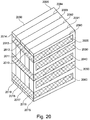
- the thermal energy store may comprise at least one bank or a plurality of banks.
- the at least one or plurality of banks may contain one or more heat exchanger means that may permit thermal energy to be transferred (e.g. by conduction and/or radiation and/or convection and/or heat pipe and/or thermal energy transfer indirectly via a thermal energy transfer fluid and/or any other means of thermal energy transfer) to and/or from at least one thermal energy sources and/or sinks.
- the heat exchanger means in at least one bank may permit thermal energy to be simultaneously or substantially simultaneously transferred (and, for example, with the same heat exchanger means, also on other occasions, non-simultaneously transferred) to and/or from two or more thermal energy sources and/or sinks.
- the heat exchanger means in at least one bank may permit thermal energy to be simultaneously (and, for example, with the same heat exchanger means, also on other occasions, non-simultaneously and/or simultaneously only in relation to some subset of the possible set of thermal energy sources/sinks) transferred to and/or from three or more thermal energy sources/sinks.
- the number of potentially simultaneous thermal energy sources and/or sinks may be four or more, five or more, six or more, seven or more, eight or more, nine or more, or ten or more. There may therefore be a plurality of thermal energy sources and/or sinks.
- the thermal store may comprise two or more banks, three or more banks, four or more banks, five or more banks, six or more banks, seven or more banks, eight or more banks, nine or more banks, or ten or more banks. There may therefore be a plurality of banks.
- the thermal store and/or each bank and/or a plurality of banks may be capable of accepting and/or storing and/or releasing thermal energy at a range of one or more temperatures to and/or from one or more thermal energy sources and/or sinks simultaneously or at different times.
- At least one or all of the banks in the thermal store may be nested.
- a configuration of banks may be wholly and/or partially nested within one another.
- At least one of the one or more outer banks may be at or substantially near the temperature of the one or more local environments enclosing the thermal energy store.
- the one or more hottest banks may be at least one of the one or more innermost nested banks (meaning that bank or those banks for which no other bank is wholly and/or mostly enclosed within it/them).
- the one or more coldest banks may be at least one of the one or more innermost nested banks (meaning that bank or those banks for which no other bank is wholly and/or mostly enclosed within it/them).
- the thermal energy store may include at least one coldest bank and one hottest bank, each of which may be an innermost bank.
- nesting, and/or wholly and/or partially enclosing banks within one another may reduce the thermal energy lost from the thermal energy store to its one or more surrounding local environments compared to the case where no nesting is used.
- At least one thermal energy sources/sinks may be external to the thermal store. At least one thermal energy source/sink may be within at least one bank of the thermal energy store.
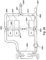
- the thermal energy store may comprise at least one thermal energy transfer connection between at least one thermal energy source and one thermal energy sink.
- the thermal energy store may comprise at least one thermal energy transfer connection between at least one thermal energy source/sink within the thermal store and at least one thermal energy sink/source external to the thermal store.
- the thermal energy store may comprise at least one thermal energy transfer connection between at least one thermal energy source/sink within at least one first bank of the thermal store and at least one thermal energy sink/source within at least one second bank of the thermal store.
- any thermal energy source/sink within a bank comprises at least some thermal energy storage material in thermal contact (whether directly physically in contact or radiatively in thermal contact or otherwise) with the one or more heat exchanger means within the bank.
- the heat exchanger means may permit thermal energy to be removed from and/or delivered to (by conduction and/or radiation and/or convection and/or heat pipe and/or thermal energy transfer indirectly via a thermal energy transfer fluid and/or any other means of thermal energy transfer) the thermal energy storage material within the bank by transfer to/from at least one thermal energy transfer connection comprising at least one thermal energy transfer medium (including but not limited to thermally conductive metal and/or high thermal conductivity plastic and/or gas and/or refrigerant and/or electromagnetic radiation and/or liquid and/or other heat transfer fluid).
- thermal energy transfer medium including but not limited to thermally conductive metal and/or high thermal conductivity plastic and/or gas and/or refrigerant and/or electromagnetic radiation and/or liquid and/or other heat transfer fluid.
- the at least one thermal energy transfer connection comprising at least one thermal energy transfer medium permits thermal energy to be transferred from/to at least one thermal energy source/sink external to the thermal store which is in thermal contact (whether directly physically in contact or radiatively in thermal contact or otherwise) with the at least one thermal energy transfer connection.
- the thermal energy transfer medium of the thermal energy transfer connection may be contained within and/or enclosed by and/or directed by one or more pipes and/or other vessels and/or enclosures (which may be closed and/or open, and may be point-to-point in nature and/or form a loop and/or form all or part of a network) to promote and/or assist and/or ensure the thermal energy transfer medium's function to transfer thermal energy from the thermal energy source at one end of the thermal energy transfer connection to the thermal energy sink as the thermal energy transfer medium may be pumped and/or otherwise caused to move by the application of external energy and/or by natural processes (such as but not limited to convection and/or thermosyphoning and/or capillary action) in such a way as to promote and/or assist and/or ensure its function to transfer thermal energy from the thermal energy source at one end of the thermal energy transfer connection to the thermal energy sink at the other or vice-versa.
- pipes and/or other vessels and/or enclosures which may be closed and/or open, and may be point-to-point
- At least one thermal energy transfer connection may comprise and/or include a heat pipe or a pipe circuit containing heat transfer fluid driven by a pump.
- Thermal energy may be caused to move within and/or through the thermal energy transfer connection by the application of external energy (such as but not limited to heat pumping and/or thermoelectric effects and/or thermionic emission) and/or by natural processes (such as but not limited to convection and/or thermosyphoning and/or capillary action) in such a way as to promote and/or assist and/or ensure the thermal energy transfer medium's function to transfer thermal energy from the thermal energy source at one end of the thermal transfer connection to the thermal energy sink at the other or vice-versa.
- external energy such as but not limited to heat pumping and/or thermoelectric effects and/or thermionic emission
- natural processes such as but not limited to convection and/or thermosyphoning and/or capillary action
- the thermal energy transfer connection may comprise and/or incorporate one or more devices for transferring heat from a lower temperature body to a higher temperature body wherein such devices may include, but are not limited to:
- the thermal store may incorporate integrally within its function and/or structure and/or control logic one or more devices for transferring heat from a lower temperature body to a higher temperature body wherein such devices may include, but are not limited to:
- the heating and/or cooling system may incorporate integrally within its function and/or structure and/or control logic one or more devices for transferring heat from a lower temperature body to a higher temperature body wherein such devices may include, but are not limited to:
- the thermal energy transfer connection may link two or more banks and may comprise and/or incorporates one or more devices for transferring heat from a lower temperature body to a higher temperature body wherein such devices may include, but are not limited to:
- the ability to transfer thermal energy of a thermal energy transfer connection and/or a part of a thermal energy transfer connection and/or heat exchanger means within a bank connected to such a thermal energy transfer connection and/or heat exchanger means external to the thermal energy store connected to such a thermal energy transfer connection may be modulated between a state in which it is maximally resistant to and/or completely incapable of transferring thermal energy and a state in which it is at its minimal resistance to transferring thermal energy and/or modulated to any degree of permissiveness between the minimum and maximum levels.
- Changes of thermal permissiveness may be accomplished by, for example, but not limited to, varying the amount of motivating energy, whether electrical or otherwise, applied to a pump and/or a heat pump and/or thermoelectric device and/or other apparatus, and/or by varying the rate of flow of a thermal energy transfer fluid, and/or by selecting from the available set of channels and/or pipes capable of carrying thermal energy transfer fluid through heat exchange means and/or thermal energy transfer connections a subset that are at a specific moment opened to carry thermal energy transfer fluid using, for example, but not limited to, valves and/or motor-driven valves and/or manifolds and/or solenoids.
- Change of thermal permissiveness may occur by changes to the physical configuration of the structure of the heat exchanger and/or thermal energy transfer connection means and/or the thermal energy transfer fluid in response to, for example, but not limited to, the physical state of the thermal store and/or some part of the thermal store, and/or the physical state of the environment surrounding the thermal store and/or some other stimulus, for instance, but not limited to, temperature changes at either end of a thermosyphon or heat pipe switching on or off and/or modulating its ability to transfer thermal energy, and/or a specially designed heat pipe with a reservoir for its thermal energy transfer fluid having that reservoir opened and/or closed, and/or a bi-metallic strip acting in response to a temperature change to open and/or close a valve.
- the modulation may be controlled and/or influenced by, for instance, but not limited to, user stimulus and/or the action of a thermostat and/or mechanical and/or electrical controller and/or control program running on a programmable computation system, responding in turn to the physical state of the thermal store and/or some part of the thermal store, and/or the physical state of the environment surrounding the thermal store.
- At least some of the banks may have overlapping and/or identical usual operating temperature ranges.
- At least some of the banks may have distinct, non-overlapping usual operating temperature ranges.
- At least two banks and/or at least one bank and at least one external thermal energy source/sink may be connected by at least one thermal energy transfer connection constituting a network and/or directed graph wherein the banks may constitute nodes and the thermal energy transfer connections may constitute edges.
- At least one thermal energy transfer connection may transfer thermal energy in only one direction and/or can transfer with much higher permissiveness in one direction and very low permissiveness in the other (for example, but not limited to, from a first bank to a second bank, only when at that moment the thermal energy storage material within the first bank is at a temperature higher than the thermal energy storage material within with the second bank, but never from said second bank to said first bank).
- One or more single-direction-only thermal energy transfer connections may comprise and/or include, for instance, but not limited to, heat diodes and/or specially configured heat pipes and/or thermosyphons, and/or pumped circuits operating only when thermostats and/or thermocouples in the banks and/or thermal energy sources/sinks at either end of report a temperature higher at one end than at the other but not when the temperature difference goes the other way, and/or selective emissivity surfaces and/or selective emissivity glass and/or double glazing and/or triple glazing and/or inert gas and/or vacuum.
- Every external heat source/sink may be directly connected by thermal energy transfer connection means to every bank within the thermal store.
- Every bank within the thermal store may be connected to every other bank within the thermal energy store by thermal energy transfer connection means.
- At least one external thermal energy source/sink it may be connected to at least one bank within the thermal energy store but it may not be connected to every bank within the thermal energy store.
- At least one bank within the thermal store it may be connected to at least one other bank within the thermal energy store but it may not be connected to every other bank within the thermal energy store.
- Every bank within the thermal store may be connected to only the next bank hotter/colder than the given bank, wherein the temperature of each bank means, for example, but not limited to, phase transition temperature of thermal storage material within each bank, and/or the minimum and/or maximum and/or centre of each bank's usual operating temperature range.
- At least one thermal energy source external to the thermal energy store and/or at least one source bank within the thermal energy store may lack a direct thermal energy transfer connection to/from at least one destination bank within the thermal energy store and/or at least one thermal energy sink external to the thermal energy store.
- Thermal energy can still be transferred between the source and destination (or vice-versa) by utilising as a substitute for the missing direct thermal energy transfer connection at least a sequence of a first thermal energy transfer connection leading to a first intermediate bank followed by a second thermal energy transfer connection leading to the original destination.
- Transfer of thermal energy from the source using the first thermal energy transfer connection causes the thermal energy to be added to the energy stored in the at least one intervening bank, where it may be stored temporarily. Simultaneously and/or previously and/or later thermal energy may be removed from the said intervening bank and transferred using the second thermal energy transfer connection to the destination.
- the sequence of intermediate transfers may include at least two intermediate banks and at least three thermal energy transfer connections.
- At least three sources/destinations for thermal energy transfers may share a single thermal energy transfer connection.
- the thermal energy transfer connection may be shared by virtue of being continuously connected to the heat exchangers of each of the at least three sources/destinations.
- the thermal energy transfer connection may be shared at some times by virtue of being on at least some occasions connected to the heat exchangers of at least two of the at least three sources/destinations.
- One or more thermal energy storage banks may be connected to another set of one or more thermal energy storage banks by thermal energy transfer connection means wherein said means may permit the controlled and/or deliberate and/or uncontrolled transfer of thermal energy between banks.
- the thermal energy transfer connections between banks may be changed during the use of the system by, for example but not limited to, physically making and/or breaking pipe-work and/or other connections, and/or by switching on and/or off and/or into intermediate positions valves and/or pumps and/or heat pumps and/or other switchable and/or controllable elements and/or by changing the ability to transfer thermal energy of heat pipes and/or any other means of controlling heat transfer known to the art.
- a source may at another time and/or at the same time also be a destination
- the sources and/or destinations of thermal energy transfers may be switched in succession and/or in parallel amongst one or more thermal energy sources/sinks (whether external to a thermal energy store and/or thermal energy storage banks within a thermal energy store) and one or more thermal energy storage banks of a thermal energy store.
- the switching of sources/destinations may result from physical changes to properties (for example, but not limited to temperature) of the system and/or the environment surrounding the system and/or the component parts of the system (such as, but not limited to, thermal energy storage banks and/or thermal energy sources/sinks) causing natural physical changes to some element of the system (for example, but not limited to, expansion of a metal and/or variable expansion of a bi-metallic strip, and/or density change and/or evaporation and/or condensation of a thermal energy transfer fluid) that may result in change to the function of some part of the system (such as, but not limited to, opening and/or closing and/or variation of the state of a valve, and/or variation of the ability of a heat pipe to transmit heat) wherein such changes were intended by a system designer.
- properties for example, but not limited to temperature
- the environment surrounding the system and/or the component parts of the system such as, but not limited to, thermal energy storage banks and/or thermal energy sources/sinks
- a control system may choose and/or switch the sources and/or destinations of thermal energy transfers in succession and/or in parallel amongst one or more thermal energy sources/sinks (whether external to a thermal energy store and/or thermal energy storage banks within a thermal energy store) and one or more thermal energy storage banks of a thermal energy store.
- control system may calculate the relative overall system coefficient of performance and/or efficiency and/or any other performance metric for one or more potential thermal energy transfers at any time and the control system may choose a more beneficial or the most optimal choice of such transfers in relation to parameters set by an over-arching control system and/or according to criteria established by the thermal energy storage system designer and/or user and/or purchaser and/or legal criteria and/or safety criteria and/or any other design and/or usage and/or benefit criteria, and switch the sources and/or destinations accordingly.
- the amount and/or temperature of thermal energy available from/acceptable by a thermal energy source/sink external to the thermal energy store may be variable over time.
- the amount and/or temperature of thermal energy available from/acceptable by a thermal energy source/sink external to the thermal energy store may be variable over time due to user choices, for example but not limited to:
- the amount and/or temperature of thermal energy available from/acceptable by a thermal energy source/sink external to the thermal energy store may be variable over time due to the process of operation of the thermal energy source, for example but not limited to:
- the amount and/or temperature of thermal energy available from/acceptable by a thermal energy source/sink external to the thermal energy store may be variable over time due to intrinsic or natural variability of the source/sink itself, for example but not limited to:
- At least some sources and/or destinations of thermal energy transfers may be switched in succession and/or parallel such that at least at some times thermal energy may be transferred from one external source of thermal energy to a selected bank that has at said times a lower average and/or maximum and/or minimum temperature in its thermal energy storage material than the temperature at said times of the external source of thermal energy.
- the selected bank may be chosen because it is, at that time, the hottest bank (i.e. that bank having the highest average and/or maximum and/or minimum temperature of its thermal energy storage material) amongst all banks of the thermal energy store that have temperatures lower than the external thermal energy source.
- the selected bank may be chosen because it is, at that time, the bank most depleted in thermal energy by some measure, for example, but not limited to the bank having the lowest average and/or maximum and/or minimum temperature of its thermal energy storage material, and/or wherein the thermal energy storage material may be a phase change material being the closest (whether on an absolute measure and/or proportional to the maximum possible for that bank) to being entirely in its lowest energy state, for example but not limited to, frozen.
- thermal energy transfer fluid that has already been directed by one thermal energy transfer connection from the external thermal energy source to a first bank
- additional thermal energy transfer connections in sequence to heat exchanger means in one or more additional banks wherein the one or more additional banks are visited in descending sequence of average and/or maximum and/or minimum temperature of the thermal energy storage material within each bank.
- At least some sources and/or destinations of thermal energy transfers may be switched in succession and/or parallel such that at least at some times thermal energy is transferred to one external sink of thermal energy from a selected bank that has at said times a higher average and/or maximum and/or minimum temperature in its thermal energy storage material than the temperature at said times of the external sink of thermal energy.
- the selected bank may be chosen because it is, at that time, the coldest bank (i.e. that bank having the lowest average and/or maximum and/or minimum temperature of its thermal energy storage material) amongst all banks of the thermal energy store that have temperatures higher than the external thermal energy sink.
- the coldest bank i.e. that bank having the lowest average and/or maximum and/or minimum temperature of its thermal energy storage material
- the selected bank may be chosen because it is, at that time, the bank containing the largest quantity of thermal energy by some measure, for example, but not limited to the bank having the highest average and/or maximum and/or minimum temperature of its thermal energy storage material, and/or wherein the thermal energy storage material may be a phase change material being the closest (whether on an absolute measure and/or proportional to the maximum possible for that bank) to being entirely in its highest energy state, for example but not limited to, molten.
- thermal energy may be transferred to the external thermal energy sink from the selected bank
- potential to transfer thermal energy from other banks in the thermal energy store remains, and a further bank and/or banks may be selected to provide some and/or all of the remaining thermal energy that could be potentially transferred in sequence and/or at the same time by, for example, but not limited to, causing a thermal transfer fluid to be first directed by an arrangement of one or more additional thermal energy transfer connections in sequence to heat exchanger means in one or more additional banks, wherein the one or more additional banks may be visited in descending and/or ascending sequence of average and/or maximum and/or minimum temperature of the thermal energy storage material within each bank before it is directed by a final thermal energy transfer connection to the external thermal energy sink from the last bank.
- Thermal energy transfer fluid may flow around a circuit that may include an external source/sink of thermal energy and at least one bank of a thermal energy store selected from the full set of such banks.
- the number and/or order and/or phase transition temperature and/or current average and/or maximum and/or minimum temperature of banks to include in the transfer of thermal energy from/to an external source/sink may be chosen such that the return temperature of any thermal energy transfer fluid that may flow back from the thermal energy store may be better adapted to and/or optimally matched to some characteristic of the external source/sink, for example, but not limited to, the temperature at which thermal energy transfer fluid flowing into the external source/sink may deliver and/or collect and/or reject and/or generate and/or convert thermal energy most optimally, for example, but not limited to:
- the objective to better and/or optimally match some characteristic of the external source/sink is balanced against the objective to maintain certain target quantities of, for example but not limited to, thermal energy in each bank and/or certain target temperatures, which may be changed from time-to-time, by changing from time-to-time the number and/or order and/or phase transition temperature and/or current average and/or maximum and/or minimum temperature of banks to include in the thermal energy transfers between the thermal energy store and at least one external sources/sinks.
- certain target quantities of, for example but not limited to, thermal energy in each bank and/or certain target temperatures which may be changed from time-to-time, by changing from time-to-time the number and/or order and/or phase transition temperature and/or current average and/or maximum and/or minimum temperature of banks to include in the thermal energy transfers between the thermal energy store and at least one external sources/sinks.
- the objective to maintain and/or achieve certain target quantities of, for example but not limited to, thermal energy in each bank and/or certain target temperatures, which may be changed from time-to-time, may be achieved by a control system adapting the thermal energy transfers within and to/from the store.
- Such adaptation may be performed having reference to current and/or historical information and/or future-looking projections about physical parameters and/or user behaviour related to the thermal energy store itself and/or its banks and/or its thermal energy storage materials, and/or the environment immediately surrounding the thermal energy store, and/or the demand patterns of any services supplied by the thermal energy store (for example, but not limited to, the schedule of production of a factory using such thermal energy), and/or the wider environment (for example, but not limited to, current/projected outdoor temperature and/or solar insolation and/or cloud cover and/or projected and/or actual availability of fuel and/or electrical energy), and/or user behaviour (for example, but not limited to, user presence or absence and/or user preferences for comfort temperature).
- the thermal energy store for example, but not limited to, the schedule of production of a factory using such thermal energy
- the wider environment for example, but not limited to, current/projected outdoor temperature and/or solar insolation and/or cloud cover and/or projected and/or actual availability of fuel and/or electrical energy
- the external source of thermal energy may be a fluid and/or environment containing waste and/or excess thermal energy from a process (for example, but not limited to, exhaust warm air from a building in a cold environment and/or exhaust cool air from a building in a warm environment and/or waste warm water from bathing and/or showering and/or oil in a heat engine requiring cooling before re-use and/or cooling fluid from a fuel cell and/or a biogas digester and/or a bio-fuel production plant).
- a process for example, but not limited to, exhaust warm air from a building in a cold environment and/or exhaust cool air from a building in a warm environment and/or waste warm water from bathing and/or showering and/or oil in a heat engine requiring cooling before re-use and/or cooling fluid from a fuel cell and/or a biogas digester and/or a bio-fuel production plant).
- the external source of thermal energy may be a fluid and/or environment containing waste and/or excess thermal energy and this thermal energy may be transferred to at least one bank that may be chosen specifically for having a phase transition temperature of its thermal energy storage material that makes it well adapted to absorbing the waste thermal energy.
- thermal energy sinks/sources external to the thermal energy store there may exist, from the at least one bank that absorbs waste and/or excess thermal energy, no direct thermal energy transfer connections to thermal energy sinks/sources external to the thermal energy store (apart from the one or more thermal energy transfer connections to the waste and/or excess thermal energy source).
- At least one thermal energy transfer connection may exist, from the at least one bank that absorbs waste and/or excess thermal energy, at least one thermal energy transfer connection (specifically including those where machines are used to transfer thermal energy from lower to higher temperature) to at least one other banks within the thermal energy store.
- the effect may be to capture waste and/or excess heat from a fluid and/or environment at a temperature below that at which such waste/excess heat could usefully directly contribute to a useful service of the thermal energy system and to effect such capture at an energy transfer rate that is adapted to the availability of waste/excess heat into one or more banks containing thermal energy storage materials at temperatures below those at which waste/excess heat could usefully directly contribute thermal energy to a useful service of the thermal energy system and to use devices (for example but not limited to heat pumps) to transfer thermal energy from these one or more lower temperature banks to one or more higher temperature banks (which are at temperatures from which they can usefully directly contribute thermal energy to a useful service of the thermal energy system) at a rate that may differ substantially from the waste/excess energy capture rate.
- devices for example but not limited to heat pumps
- the rate of thermal energy transfer from lower to higher temperature banks may be lower than the peak rate at which thermal energy transfers to the lower temperature banks from the waste/excess energy sources.
- thermal energy may be removed from at least one bank and delivered to at least one other bank of the thermal energy store, and at the same time no thermal energy may be added to and/or removed from the thermal energy store from/to any thermal energy source/sink external to the thermal energy store.
- the configuration of the system may be such that it may be possible that on at least some occasions thermal energy may be removed from at least one bank and delivered to at least one other bank of the thermal energy store, and at the same time no thermal energy is added to and/or removed from the thermal energy store from/to any thermal energy source/sink external to the thermal energy store.
- the amount of thermal energy added to each bank may be kept in perfect balance with the amount of thermal energy removed from each bank (including any lost by unwanted and/or unintended thermal transfers and/or other losses) over a cycle which may be of any duration, for example but not limited to, some seconds and/or some minutes and/or one hour and/or several hours and/or one day and/or several days and/or one week and/or several weeks and/or one month and/or several months and/or one year and/or several years.
- One or more thermal energy transfer fluids may be re-routed and/or re-cycled through and/or via heat exchangers in thermal contact with a configuration of banks in an order intended and/or selected from time-to-time to maximise and/or enhance the thermal energy extracted from the thermal energy transfer fluid and stored into the thermal energy storage material of the banks and/or extracted from the thermal energy storage material of the banks and transferred into the thermal energy transfer fluid.
- the physical configuration of the thermal energy store may be changed during the use of the system by any of the following:
- the addition and/or connection to the thermal energy store of one or more banks may add further stored thermal energy to the thermal energy store wherein such additional thermal energy results from:
- thermal energy storage material in one or more thermal energy storage banks may be added to and/or exchanged wholly and/or partially by replacement thermal energy storage material.
- Heat may be allowed to flow in a controlled and/or an uncontrolled way from one or more banks at a higher temperature to one or more banks at a lower temperature, and/or from one or more banks at a higher temperature to one or more ambient environments in thermal contact with the thermal store, and/or from the one or more ambient environments in thermal contact with the thermal store to one or more banks at a lower temperature, by means of conduction and/or radiation and/or convection and/or heat pipe and/or transfer through a thermal transfer fluid and/or any other known physical mechanism of heat transfer.
- One or more banks may be equipped with insulation means to:
- One or more banks may be physically separated from one or more other banks of the same thermal energy store.
- Physically separated banks may be controlled by the control system as part of the same thermal energy store.
- Thermal energy transfers may be possible between said physically separated banks and one or more other banks of the same thermal energy store.
- the system may be used as a heating system and/or to provide a heating service (wherein the system may be used to add heat to at least one body and/or at least one environment external to the thermal energy store).
- the system may be used as a cooling system and/or to provide a cooling service (wherein the system is used to remove heat from at least one body and/or at least one environment external to the thermal energy store).
- the system may be used as a combined heating and cooling system used at the same and/or at different times as both a cooling system and a heating system and/or to provide at different and/or the same times heating and/or cooling services (wherein the system is used to add heat to at least one body and/or at least one environment external to the thermal energy store and, at the same and/or different times, is used to remove heat from at least one body (which may be a different and/or the same body) and/or at least one environment (which may be a different and/or the same environment) external to the thermal energy store).
- the heating and/or combined system and/or service may be used as a central and/or distributed space heating system (for example, but not limited to use in, a building and/or a vehicle and/or an outdoor space).
- the heating and/or combined system and/or may be used for water heating (for example, but not limited to use in, heating clean water for washing and/or bathing and/or cooking and/or drinks preparation and/or swimming pool heating).
- the heating and/or cooling and/or combined system and/or service may be used for heating and/or cooling thermal energy transfer fluids to provide industrial process-heat and/or cooling, and/or directly and/or indirectly heating and/or cooling working fluids of an industrial process.
- the heating and/or cooling and/or combined system and/or service may be used for heating heat-transfer fluids for use in a machine that converts thermal energy and/or temperature differences into electrical and/or mechanical energy (for example, but not limited to, a steam piston and/or a Stirling engine and/or Rankine cycle engine and/or steam turbine, whether on its own and/or attached to an electric alternator and/or dynamo, and/or a thermoelectric and/or thermionic device used as an electrical generator).
- a steam piston and/or a Stirling engine and/or Rankine cycle engine and/or steam turbine whether on its own and/or attached to an electric alternator and/or dynamo, and/or a thermoelectric and/or thermionic device used as an electrical generator.
- the cooling and/or combined system and/or service may be used as a central and/or distributed space cooling and/or air conditioning system (for example, but not limited to use in, a building and/or a vehicle and/or an outdoor space).
- a central and/or distributed space cooling and/or air conditioning system for example, but not limited to use in, a building and/or a vehicle and/or an outdoor space.
- the cooling and/or combination system and/or service may be used as a refrigeration system (for example, but not limited to use in, a domestic refrigerator and/or freezer, and/or commercial and/or industrial chilled and/or frozen storage and/or temperature controlled storage, such as but not limited to, a potato store, and/or cryogenic system).
- a refrigeration system for example, but not limited to use in, a domestic refrigerator and/or freezer, and/or commercial and/or industrial chilled and/or frozen storage and/or temperature controlled storage, such as but not limited to, a potato store, and/or cryogenic system.
- the thermal energy transfer fluid of the heating and/or cooling and/or combined system and/or service may be a liquid (for example, but not limited to, water and/or water-glycol mixture and/or water with other additives and/or a flowable oil) and/or a refrigerant (for example, but not limited to, butane and/or propane and/or ammonia and/or R-12 and/or R-22 and/or R-134a) and/or a gas (for example, but not limited to, air).
- a liquid for example, but not limited to, water and/or water-glycol mixture and/or water with other additives and/or a flowable oil
- a refrigerant for example, but not limited to, butane and/or propane and/or ammonia and/or R-12 and/or R-22 and/or R-134a
- a gas for example, but not limited to, air
- At least one bank of the thermal energy store may be used as a thermal store for at least one heating and/or cooling and/or combined service.
- At least one bank of the thermal energy store may be used as a thermal store for at least one service that may be used at least some of the time for heating and the same service may be used at least some of the time for cooling.
- At least one bank may be greatly increased in size to act as a bulk thermal energy reservoir for at least one service.
- the at least one service may be space heating and/or cooling delivered through (for example, but not limited to) radiant walls and/or under-floor heating and/or radiant ceilings and/or chilled beams and/or radiators and/or over-sized radiators and/or fan-coil radiators and/or air handling systems.
- At least one bank and/or at least one sub-parts of at least one bank of the thermal energy store may be physically co-located with and/or close to the point of delivery of the service for which it is a thermal energy reservoir and is selected to have a usual operating temperature range and/or ranges suitable to directly drive said service (for example but not limited to, one or more banks distributed at one or more taps where hot water is drawn in a domestic hot water system and/or one or more radiators and/or areas of radiant wall and/or ceiling and/or under-floor heating comprising parts of one or more banks directly in radiative and/or conductive and/or convective exchange with the one or more environments and/or bodies to be heated/cooled).
- a usual operating temperature range and/or ranges suitable to directly drive said service for example but not limited to, one or more banks distributed at one or more taps where hot water is drawn in a domestic hot water system and/or one or more radiators and/or areas of radiant wall and/or ceiling and/or under-floor heating comprising parts of one or
- the system may be used inside domestic and/or commercial and/or industrial appliances and/or machinery, for example but not limited to, a dishwasher, washing machine, etc; a hot drinks machine that also delivers chilled water and/or cold drinks; a hot/cold vending machine for food and/or drinks; a system incorporating reusable, re-chargeable heated/cooled cups which may incorporate phase change material in their operation.
- a dishwasher washing machine
- a hot drinks machine that also delivers chilled water and/or cold drinks
- a hot/cold vending machine for food and/or drinks
- a system incorporating reusable, re-chargeable heated/cooled cups which may incorporate phase change material in their operation.
- At least one bank and/or the whole thermal energy store may be used as a heat/cool battery.
- At least one thermal energy source may be an environmental and/or natural and/or waste source of heat and/or cool.
- At least one thermal energy source may be variable in temperature and/or thermal energy available over time.
- At least one thermal energy source/sink may be at least one solar thermal collector (wherein the at least one solar thermal collector may be used at different times to collect solar heat and/or reject heat to the environment), for example including but not limited to, flat plate solar collectors using a pumped loop of ethylene glycol solution in water as thermal energy transfer fluid and/or evacuated tube solar collectors using heat pipes as thermal energy transfer connection and/or roof tiles and/or dedicated solar air heaters using air as thermal energy transfer fluid and/or photovoltaic panels and/or hybrid solar thermal photovoltaic panels using heat pipes and/or direct conduction and/or air and/or a pumped loop of ethylene glycol solution in water as thermal energy transfer fluid, all heated by the sun and/or cooled by night-time radiation and/or convection and/or conduction.
- flat plate solar collectors using a pumped loop of ethylene glycol solution in water as thermal energy transfer fluid and/or evacuated tube solar collectors using heat pipes as thermal energy transfer connection and/or roof tiles and/or dedicated solar air heaters using air
- At least one thermal energy source/sink may be at least one ground source (wherein the at least one ground source may be used at different times to collect heat from the earth and/or reject heat to the earth).
- At least one thermal energy source/sink may be at least one air source (wherein the at least one air source may be used at different times to collect heat from the air and/or reject heat to the air).
- At least one thermal energy source may be at least one combustion system (for example but not limited to a wood burning stove and/or a natural gas burner and/or an oil burner).
- a combustion system for example but not limited to a wood burning stove and/or a natural gas burner and/or an oil burner.
- At least one thermal energy source may be at least one electrical heater (for example but not limited to an electric water heater, heating water as a thermal energy transfer fluid and/or a resistance element in direct thermal contact with the thermal energy storage material in a bank).
- an electrical heater for example but not limited to an electric water heater, heating water as a thermal energy transfer fluid and/or a resistance element in direct thermal contact with the thermal energy storage material in a bank.
- At least one thermal energy source may be the waste heat (that would otherwise be dissipated and/or vented via, for example but not limited to, a fan coil to a first environment) from at least one air conditioner and/or refrigeration system and/or heat pump external to the thermal energy store (wherein the primary purpose is to cool a second environment).
- At least one thermal energy source may be the waste heat (that would otherwise be dissipated and/or vented via, for example but not limited to, a fan coil and/or a cooling tower to a first environment and/or into a river and/or the sea) from at least one external system that is a heating system and/or industrial process and/or thermal electricity generation system and/or machine (for example, but not limited to, an internal combustion engine and/or a jet engine) and/or any other system of energy conversion that is less than 100% efficient and wherein some of the inefficiency is manifested as waste heat.
- a heating system and/or industrial process and/or thermal electricity generation system and/or machine for example, but not limited to, an internal combustion engine and/or a jet engine
- At least one thermal energy source may be the waste heat (that would otherwise need to be managed and/or dissipated and/or vented via, for example but not limited to, a fan coil and/or a cooling tower and/or an active cooling system and/or a heat sink to a first environment) from at least one electronic assembly and/or other machine that generates waste heat in its operation including, for example, but not limited to, computer processors and/or micro-processors and/or amplifiers and/or batteries and/or lighting equipment and/or LED lighting and/or an electric motor and/or an internal combustion engine and/or photovoltaic solar cells, wherein the waste heat is not merely managed and/or dissipated and/or vented by these means, but is also used as a way for a bank or thermal energy store or thermal energy system to gain useful thermal energy.
- At least one piece of equipment that generates waste heat may be wholly and/or partially directly embedded inside one or more banks and/or directly in thermal contact with one or more banks.
- the at least one piece of equipment that generates waste heat may be at least one chemical battery for example, but not limited to, a configuration of lithium ion battery cells, wherein the thermal energy storage material of a bank and/or sub-bank within which the batteries are embedded and/or in thermal contact is chosen to enhance the likelihood in operation and/or storage of the batteries remaining within a preferred operating temperature range thereby enhancing one or more of the safety and/or effectiveness and/or efficiency of the one or more batteries.
- At least one thermal energy source may be the waste thermal energy embodied in waste fluids, for example but not limited to exhaust air and/or waste water (that would otherwise be dissipated and/or vented via, for example but not limited to, exhaust air ducts and/or waste pipes, from a first environment into a second environment) including, for example but not limited to, waste water from domestic bathing and/or ventilation air extracted from a building at a temperature above and/or below that of a second environment and/or rainwater collected on a roof and vented to a storm drain.
- waste fluids for example but not limited to exhaust air and/or waste water (that would otherwise be dissipated and/or vented via, for example but not limited to, exhaust air ducts and/or waste pipes, from a first environment into a second environment) including, for example but not limited to, waste water from domestic bathing and/or ventilation air extracted from a building at a temperature above and/or below that of a second environment and/or rainwater collected on a roof and vente
- a high rate of waste thermal energy can be absorbed over a short period into the thermal energy storage material of one or more banks of the thermal energy store, and later and/or at the same time, at a different, for example but not limited to lower, rate the thermal energy absorbed can be transferred to other banks of the same thermal energy store and/or sources/sinks external to it.
- a smaller capacity active cooling system for example but not limited to a heat pump, may be required because peak cooling loads for waste thermal energy are reduced by temporal buffering in the thermal energy storage material of one or more banks of the thermal energy store.
- At least one thermal energy source may be at least one connection to at least one district heating system.
- At least one thermal energy source may be at least one room and/or other internal environment, wherein waste heat accumulates as a result of, for example but not limited to, occupancy by metabolising people and/or animals, and/or use of equipment that generates waste heat, and/or solar gain as a result of solar energy passing through windows and/or other apertures open to the ingress of visible and/or ultra-violet and/or infra-red radiation and being absorbed by one or more surfaces internal to the room with a resultant rise in thermal energy and/or temperature and/or re-radiated as longer wavelength infra-red and/or other thermal radiation and/or warming the air in the room.
- the at least one thermal energy source which is at least one room and/or other environment, wherein waste heat accumulates, may be connected to the thermal energy store by at least one thermal energy transfer connection that comprises all and/or part of a system designed to extract waste thermal energy from the at least one room and/or other environment, comprising, for example but not limited to, an air conditioning and/or comfort cooling and/or radiant cooling system and/or designed to alternate between extracting waste thermal energy at some times and delivering desired heat at others, present in the one or more room and/or other environment.
- a thermal energy transfer connection that comprises all and/or part of a system designed to extract waste thermal energy from the at least one room and/or other environment, comprising, for example but not limited to, an air conditioning and/or comfort cooling and/or radiant cooling system and/or designed to alternate between extracting waste thermal energy at some times and delivering desired heat at others, present in the one or more room and/or other environment.
- At least one thermal energy sink may be a room and/or environment requiring to be heated and/or cooled.
- the thermal energy transfer connection between the whole of and/or at least one banks of the thermal energy store and a room and/or environment requiring to be heated and/or cooled may comprise at least one of, for example but not limited to a circuit and/or network of pipes and/or ducts carrying thermal transfer fluid such as ethylene glycol and/or R134a and/or air, and/or heat pipes and/or direct conduction and/or radiative transfer, transferring thermal energy to at least one of radiant walls and/or under-floor heating and/or radiant ceilings and/or chilled beams and/or radiators and/or over-sized radiators and/or fan-coil radiators and/or air handling systems.
- thermal transfer fluid such as ethylene glycol and/or R134a and/or air
- heat pipes and/or direct conduction and/or radiative transfer transferring thermal energy to at least one of radiant walls and/or under-floor heating and/or radiant ceilings and/or chilled beams and/or radiators and/or over-sized radiators and/or fan-coil radiators
- the room and/or environment may constitute a location wherein perishable articles, for example but not limited to food and/or biological specimens and/or formerly living beings, are kept to delay processes of decay and/or promote freshness, for example, but not limited to, a larder room and/or domestic and/or commercial and/or industrial refrigerator and/or freezer and/or chiller and/or vehicle and/or container and/or cryogenic storage and/or morgue.
- perishable articles for example but not limited to food and/or biological specimens and/or formerly living beings, are kept to delay processes of decay and/or promote freshness, for example, but not limited to, a larder room and/or domestic and/or commercial and/or industrial refrigerator and/or freezer and/or chiller and/or vehicle and/or container and/or cryogenic storage and/or morgue.
- One or more banks of a thermal energy store may be connected to a source/sink of thermal energy comprising equipment that uses thermal energy to control the humidity of air by, for example but not limited to, using removal of thermal energy to cool humid air below its dew point and thereby cause water vapour to condense out and thereby reduce the humidity of the air, and/or thereafter adding thermal energy to re-heat the now dried air to a user comfort temperature, and/or adding thermal energy to water to evaporate some water and thereby add humidity to air.
- One or more banks of a thermal energy store may be used to store excess and/or waste heat from a cooling system during the daytime (and/or any other period of peak heat load) so that the heat can be dumped at a later time when conditions allow that to be done with lower use of additional pumping and/or heat pumping energy, for example, but not limited to, during the night when air temperatures are colder and/or a solar panel can radiate heat to the night sky.
- One or more banks of a thermal energy store may be used to store excess and/or waste heat from a cooling system during the daytime (and/or any other period of peak heat load) so that the heat can be dumped at a later time selected such that any required additional pumping and/or heat pumping energy will have a lower cost and/or be more available, for example but not limited to, when a lower costs night-time tariff from an electric utility is in force and/or when the wind blows on a wind turbine to generate electrical and/or mechanical power.
- Any heat pumping and/or pumping of thermal energy between banks and/or to/from banks and thermal energy sinks/sources may be, in at least some cases and/or on at least some occasions, made to occur at a time selected such that any required additional pumping and/or heat pumping and/or heating and/or cooling energy will have a lower cost and/or be more available, for example but not limited to, when a lower costs night-time tariff from an electric utility is in force and/or when the wind blows on a wind turbine and/or the sun shines on a photovoltaic panel to generate electrical and/or mechanical power.
- Any heat pumping and/or pumping of thermal energy between banks and/or to/from banks and thermal energy sinks/sources may be, in at least some cases and/or on at least some occasions, selected to occur when the temperatures of the banks and/or the thermal energy sinks/sources are such as to make the temperature difference between the source and destination of each thermal energy transfer optimal and/or preferable and/or better than at other times (whether on the basis of historical record and/or predicted future performance), so as to reduce the use of additional pumping and/or heat pumping and/or heating and/or cooling energy.
- the phase transition utilised for thermal energy storage may be one or more of:
- the phase transition may absorb and/or release substantially more energy at the said one or more temperatures or one or more sub-ranges of temperatures than would be the case taking account solely of the thermal energy absorbed and/or released as specific heat at the said one or more temperatures or one or more sub-ranges of temperatures.
- One or more thermal energy storage materials may be combined with one or more additives to promote desirable properties and/or suppress undesirable properties and/or otherwise modify the phase transition wherein the effect of the additives is, for example but not limited to, one or more of:
- One or more thermal energy storage materials and/or additives may be chosen to improve and/or optimise a trade off between their cost and/or safety and/or physical density and/or phase transition temperature and/or the energy absorbed and/or released during phase transition and/or the characteristics of the phase transition and/or the minimisation of volume change from one side to the other of the phase transition and/or narrowness of their phase transition temperature range and/or similarity and/or difference of their phase transition temperatures when absorbing and/or releasing energy and/or repeatability of releasing and/or absorbing thermal energy and/or loss of energy associated with absorbing and subsequently releasing thermal energy and/or thermal conductivity and/or materials compatibility and/or other physical properties according to criteria established by the thermal energy storage system designer and/or user and/or purchaser and/or legal criteria and/or safety criteria and/or any other design and/or usage and/or benefit criteria.
- the in the method of the present invention may be self-powering for at least some of its functions by allowing for heat transfers from hotter to colder banks via, for example, but not limited to, a steam piston and/or a Stirling engine and/or Rankine cycle engine and/or steam turbine, whether on its own and/or attached to an electric alternator and/or dynamo, and/or a thermoelectric and/or thermionic device used as an electrical generator.
- the in the method of the present invention may also compensate dynamically for change in the thermal energy storage materials properties (e.g. melting temperature; sharpness of melting temperature) over time.
- thermal energy storage materials properties e.g. melting temperature; sharpness of melting temperature
- the in the method of the present invention may also be for both heating and cooling and wherein at least one bank may act as a source of thermal energy so as to increase the temperature of one or more thermal energy sinks and simultaneously and/or at a different time may act as a sink of thermal energy so as to reduce the temperature of one or more thermal energy sources.
- the thermal in the method of the present invention may also comprise two banks so there is no heat pumping apparatus in the thermal energy transfer connection between them. Carrying out the method of the present invention also allows water heating by passing through several banks at rising phase transition temperatures. This allows mixed grade heat to be used for water heating.
- Thermal energy storage as described in the present application can refer to a number of technologies that store energy in a thermal reservoir for later reuse.
- the described technologies can be employed to balance energy demand between day time and night time.
- the thermal reservoir may be maintained at a temperature above (hotter) or below (colder) than that of the ambient environment.
- FIG. 1 is a representation of an energy storage system according to the present invention generally designated 100.
- the heating/cooling system comprises a series and/or a collection of banks 102a, 102b, 102c, 102d, 102e, 102f, 102g and 102h which are used to collect and store thermal energy from, for example, a solar thermal panel (not shown) and, for example, later deliver thermal energy to heat up cool water.
- Figure 1 shows eight banks, the invention is intended to cover any suitable number of banks.
- 102d, 102e, 102f, 102g, 102h contains a different phase change material which therefore has a different melting point to store heat.
- insulation 104 around the banks 102a, 102b, 102c, 102d, 102e, 102f, 102g, 102h.
- Bank 102a is at temperature of about 15oC by virtue of containing a suitable phase change material with a phase transition temperature of 15oC.
- bank 102b is at temperature of about 20oC
- bank 102c is at temperature of about 25oC
- bank 102d is at temperature of about 30oC
- bank 102e is at temperature of about 35oC
- bank 102f is at temperature of about 40oC
- bank 102g is at temperature of about 45oC
- bank 102h is at temperature of about 50oC.
- Figure 1 shows specific temperatures, the present invention is intended to cover any selection of temperatures.
- each of the banks in the energy storage system 100 contain heat exchangers 109a, 109b, 109c, 109d, 109e, 109f, 109g, 109h .
- Cold water is inserted from an inlet 106 into heat exchanger 109a and passes through heat exchangers 109b, 109c, 109d, 109e, 109f, 109g and 109h. Heated water may exit outlet 108 at about 45oC. Heat from, for example, a solar thermal panel (not shown) and/or from the environment or other heat sources may be fed in from any of feed points 110 using heat exchange means (not shown).
- the heat storage medium in each of banks 102a, 102b, 102c, 102d, 102e, 102f, 102g, 102h could be water (or some other heat storage medium), but preferably the heat storage medium is a suitable phase change material (PCM)
- PCM phase change material
- the different banks of the multi-bank PCM heat store are kept in equilibrium (i.e. as much heat is added to any given bank as is extracted from the same bank via water heating and incidental losses) it can at any given moment accept heat from any environmental heat source at any temperature from over 15oC to over 50oC (for the example in Figure 1 ) and route it to the appropriate bank.
- any environmental heat source at any temperature from over 15oC to over 50oC (for the example in Figure 1 ) and route it to the appropriate bank.
- the control system of the thermal store can choose an appropriate heat transfer fluid flow rate and bank into which to load heat, for instance:
- heat transfer fluid that started at the solar panel at say 60oC is, after it exits the heat exchanger in the 50oC bank, still at or above 50oC. This can be routed now to load heat to the 45oC bank, and so on down to the coolest bank.
- heat transfer fluid can be made to return to the solar panel at around 15oC in this example to be warmed again. So almost all the useful heat collected by the solar panel can be extracted and stored. Also the solar thermal panel itself will perform more efficiently, with lower thermal losses, by virtue of the low temperature of heat transfer fluid entering it.
- a further preferred embodiment is to nest the banks of PCM inside each other like Russian dolls.
- Such an energy storage system 200 is shown in Figure 2 which has nested banks 202a, 202b, 202c, 202d, 202e, 202f, 202g, 202h.
- Bank 202a is at temperature of about 15oC
- bank 202b is at temperature of about 20oC
- bank 202c is at temperature of about 25oC
- bank 202d is at temperature of about 30oC
- bank 202e is at temperature of about 35oC
- bank 202f is at temperature of about 40oC
- bank 202g is at temperature of about 45oC
- bank 202h is at temperature of about 50oC.
- the innermost bank 202h would be the hottest, with the outermost bank 202a the coolest. Of course there would still be maintained some insulation between each layer. In this case the loss of heat from each bank would be proportional to the much smaller ⁇ T between each bank and its outer neighbour.
- Figure 1 separately insulates each bank from the local environment. If the insulation is of identical type and thickness around each bank then the higher temperature banks will lose more heat to their surroundings than the lower temperature ones, because heat loss is proportional to the ⁇ T between the bank and its surroundings.
- the embodiment of Figure 1 or a regular hot water tank, over time loses energy to the local environment.
- the nested multi-bank PCM heat store of Figure 2 can, by suitable choice of outermost bank temperature to be equal to or lower than the local environment temperature, be made virtually neutral. For example in Figure 2 , if the local environment is at 20°C, the thermal store's outermost 15°C layer will slowly absorb heat from the local environment.
- energy storage system 200 will store the heat put into it much better than energy storage system 100 (although over time the grade of heat it holds will reduce as heat flows from the high temperature core out to lower temperature banks around it). It will also be cool to the touch making it possible to integrate it into places one would not want to put a hot water tank.
- FIG. 3 relates to an energy storage system 300.
- Bank 302c is preferably the largest bank as this is connected to an underfloor heating system 310 which has insulation 312 around its pipes where they pass through other banks 302a and 302b in the energy storage system 300.
- the energy storages system 300 contains an inlet 304 for mains cold water and heat exchangers 306 in each of the banks 302a, 302b, 302c, 302d, 302e, 302f.
- There is also an outlet 308 for hot water which also benefits from insulation 312 when it passes through banks 302e, 302d, 302c, 302b and 302a.
- FIG. 4 is a further energy storage system 400 according to the present invention.
- MPCM multi-bank phase change material
- the energy storage system 400 also has a heating loop 410 and a heating/cooling loop 412.
- MPCM multi-bank phase change material
- a heat pump 424 may be used to extract heat from selected banks (any of 422a, 422b, 422c, 422d) of cold store 420 and load it at higher temperatures into selected banks (any of 402a, 402b, 402c, 402d, 402e, 402f) of heat store 410 (for clarity purposes the heat exchangers to and from heat pump 424 have been omitted).
- heat can be removed from a bank of the PCM cool store using a heat pump and concentrated to a suitable higher temperature. This higher temperature heat could be released to the environment; however an alternative is to add it to a bank of a PCM heat store that needs additional heat.
- the highlighted path in Figure 4 shows heat being removed from 10oC bank 422b of cool store 420 via heat pump 424 and entering heat store 35oC bank 402c.
- the benefit is high since this single use of a heat pump is both adding heat to the heat store 410 for later use (e.g. for hot water, space heating) and simultaneously (and with the same energy to drive the heat pump) removing heat from the cool store 420, thereby adding cool to it for later use (e.g. for air conditioning).
- Figure 5 therefore shows a further energy storage system 500 with a cold store 510 and heat store 512 joined together, having two centres, one hot and one cold and an outermost bank at or close to room temperature (assuming it will be housed inside a building's thermal envelope).
- FIG. 6 a similar shared heat and cold store 600 is shown which has a single time-shared heat pump with many-to-many connectivity, connected on its input side to all except the hottest bank (the connection is multiplexed, i.e. a choice can be made of which cold source to draw upon) and on its output side connected by a multiplexed connection to all except the coldest bank.
- Multi-Bank PCM Heat/Cool Stores will need to re-balance the amount of heat stored between banks. Sometimes this will be possible purely by controlling the flow of heat from environmental sources to each bank; however it is likely that this will not always be possible.
- a multi-bank PCM heat store could be configured with one or more heat pumps. These could be connected by heat exchangers, valves, etc in such a way that the heat pump(s) can pump heat from any bank to any warmer bank.
- a heat pump can be time multiplexed to perform dual duty both as a bank to bank heat pump and also as an external heat pump as in practice, there will be occasions when it makes sense to transfer heat directly from colder to hotter banks of a thermal store, and others when it makes sense to remove heat to or extract heat from the surrounding environment. With suitable configuration of pipes and valves it is possible to allow for all these possibilities. In that case control algorithms can add this direct transfer to their repertoire and optimise for this as well, thus dynamically choosing it when appropriate. This is shown in Figure 7 where energy storage system 700 has a heat pump 706 performing this dual duty. There is an environmental heat source 708. (For clarity purposes the insulation and some of the valves have been omitted).
- an alternative is to interpose a lower capacity heat pump between each bank.
- This is illustrated in the energy storage system 800 shown in Figure 8 which has a series of banks 802a, 802b, 802c, 802d, 802e, 802f, 802g, 802h, 802i, 802j between which are interposed heat pumps 804. (For clarity pipework, heat exchangers connecting heat pumps 804 to the banks and insulation are omitted). There is also an external heat pump 806 allowing heat to be drawn from an environmental source.
- An energy storage system 900 comprises a series of banks where heated water or other heat transfer fluids may be used for a variety of purposes.
- Inlet 902 is used as a heating return; outlet 904 is used for underfloor heating; outlet 906 is used for fan-coil radiator flow; outlet 908 is used for radiator flow; inlet 912 is used for cold mains; outlet 910 is used for hot water; inlet 916 is used for air conditioning return and outlet 914 is used for air conditioning flow.
- Inlet 918 is an environmental heat source.
- Heat pump 920 may be used as a heat pump or by-passed if the environmental or solar heated water from a solar panel 922 is at a sufficiently high temperature. (The insulation has been omitted for clarity and multiplexing valves omitted for clarity. On the left-hand side of Figure 9 flows are only shown and returns are omitted for clarity. Furthermore, pathways for cooling via night-time radiation from solar panel are omitted for clarity).
- a thermal store could instead be configured with one or more additional (colder) banks of PCM that have temperatures lower than the environmental source. The heat from the environmental source can flow into these colder banks without initial heat pumping.
- Heat pumps interposed between each bank of the thermal store can be used to pump the heat so acquired to hotter banks; thereby making the heat useful and keeping the colder banks at a low enough temperature that they can continue to capture environmental heat thus eliminating the need for any external heat pumps.
- Figures 10 and 11 which represent energy storage systems 1000, 1100, respectively.
- FIG. 10 there is an external heat pump 1004 that raises the heat of the ground water 1020 to 35oC - 50oC+ in order that it can be loaded into the PCM banks 1002a, 1002b, 1002c, 1002d at 35, 40, 45, 50oC, respectively.
- the heated water is fed to radiator 1006.
- FIG. 11 there are PCM banks 1102a, 1102b, 1102c, 1102d which have heat pumps 1104 interposed between each bank. The heated water is fed to radiator 1106.
- Bank 1102a specially configured with PCM with melting point 0oC, is introduced. Heat is captured from ground water 1120 by passing this 5oC fluid through heat exchange with the 0oC bank 1102a. Later or simultaneously, this heat is pumped to the warmer banks using heat pumps 1104.
- FIG. 12 is a cut-through representation of an embodiment of a solar collector integrating phase change material (PCM) storage with the solar collector.
- PCM phase change material
- a thin flexible plastic outer jacket 1201 contains a PCM 1203 (which may be water or another PCM or a PCM composite).
- Pipes 1204, 1205, 1206 carrying glycol, brine or another heat transfer fluid (HTF) run through the solar collector, connected in series order 1204, 1205, 1206, or in parallel or in a series-parallel fashion.
- HTF heat transfer fluid
- the thin, flexible walls of the collector adapt to expansion or contraction on freezing/thawing of the PCM.
- the collector walls may be pillowed, combined with internal ribs, in the manner of an inflatable mattress, (airbed) to maintain a broadly flat, thin section while permitting expansion/contraction.
- the walls can be black or coloured (to promote absorption of incident solar irradiance) or transparent to allow solar irradiance to penetrate to the PCM.
- the PCM may be mixed with a black dye or a selective absorber such as TiNOx to promote absorption of light to heat.
- the PCM forms a large thermal reservoir at the point of collection of solar energy, and may form one bank (or if several collectors with different temperature PCMs are used, several banks) of a heat store of the present invention.
- different pockets of the same collector may contain different PCMs with different melting points.
- the internal ribs separating pockets positioned as illustrated 1220, 1221) additionally serve to separate the different PCM materials, and may preferentially be insulated, and may incorporate a thermoelectric device or other heat pumping means.
- HTF flows in sequence through serially connected tubes 1204, 1205, 1206 entering tube1204 at a colder temperature and exiting tube 1206 at a hotter temperature; also preferentially the different PCMs are arranged so that pocket 1210 contains the lowest melting point PCM and pocket 1212 contains the highest melting point PCM.
- FIG. 12 is merely illustrative of a specific embodiment of an integrated solar collector according to the present invention. Those skilled in the art will be able to adapt other embodiments for example:
- Figure 13 illustrates a vacuum tube solar thermal collector with integrated multi bank PCM storage according to the present invention.
- Glass tube 1301 contains metal collector plate 1302 equipped with heat pipe 1303 in (partial) vacuum 1304 in accordance with prior art.
- heat pipe 1303 is extended into and through PCM banks 1310, 1311 and 1312, each containing a different temperature of PCM or PCM composite (for example the PCM in 1310 may melt at 32°C, in 1311 at 45°C and in 1312 at 58°C).
- the number of such PCM banks is three for illustrative purposes only and may vary.
- Insulation 1330 and 1331 sits between (and not illustrated for clarity, around) the PCM banks. At the point marked 1340 and at each point where the heat pipe penetrates inter-bank insulation 1330 and 1331, it is equipped with heat diode or switchable means to ensure heat does not leak back from the PCM in the bank via the heat pipe to the solar collector.
- heat-pumping means e.g. thermoelectric devices
- PCM bank 1310 may be integrated in cavities extending through the insulation 1330 such that it can extract heat from PCM bank 1310 and deliver it to PCM bank 1311 (and similarly via cavities in 1331 from 1311 to 1312).
- PCM banks 1310, 1311, 1312 are equipped with fins or other means to promote the transfer of heat from the heat pipe into the PCM. Such fins or other means also promote transfer of heat to tubes 1320, 1321, 1322 containing heat transfer fluid, which respectively penetrate PCM banks 1310, 1311, 1312. Such tubes may be connected across a number of the vacuum tube solar thermal collector with integrated multi bank PCM storage embodiments in Figure 13 in parallel to provide three (or a number) of HTF circuits that can extract heat at different temperatures.
- each vacuum tube solar thermal collector with integrated multi bank PCM storage the PCM banks 1320, 1321, 1322 can be visited in sequence so as to raise the temperature of a single HTF over a larger temperature range.
- FIG 14 is a representation in which a heat pipe 1401 is connected to a PCM bank 1421 only by a thermoelectric device (TED) 1411 (insulation surrounds the PCM bank, a tube containing heat transfer fluid may pass through it, and it may contain fins or composite material, but these are omitted for clarity).
- TED thermoelectric device
- heat pipe 1402,1403 Specific sections of heat pipe 1402,1403 are illustrated, attached via TEDs 1412, 1413 to PCM banks 1422, 1423 respectively. In both cases the heat pipe is illustrated at 20°C and the PCM bank at 32°C.
- a battery 1432 (or alternatively any other electrical power source) is connected in circuit (switched via switching apparatus not illustrated) with TED 1412 such that TED 1412 pumps heat from heat pipe segment 1402 to PCM bank 1422.
- a resistive load 1433 (illustrative of the broader class of all electrical loads) is connected in circuit (switched via switching apparatus not illustrated) with TED 1413. Heat flows from PCM bank 1423 via TED 1413 to colder heat pipe 1403. This causes TED 1413 to make a current flow in the circuit.
- Energy can be extracted from the bank via a user or automatic choice between two mechanisms:
- FIG. 15 is a representation of a specific embodiment of a radiator and ceiling panel 1500 comprising two insulated banks of PCM 1501 (having an illustrative melting point temperature of 18°C), 1502 (having an illustrative melting point temperature of 24°C), each PCM bank having internally fins, or conductivity enhancing material composited with the PCM, to allow heat to flow to/from a flat heat pipe 1520, arranged so that at another point it forms the bottom surface 1523 of the ceiling tile in radiative contact with a room.
- a TED 1510 is in contact with both PCM banks 1501 and 1502 such that upon application of electrical power it can pump heat from 1501 to 1502 (or at another time it can generate electrical power by allowing heat to flow from 1502 to 1501.
- Figure 16 is a representation of a specific embodiment of a ceiling tile 1600 (or similar radiator) having a single bank of PCM 1610 (at a temperature e.g. 24°C) plus a thermoelectric device ("TED") 1620 connecting PCM bank 1610 to a heat spreader 1630 in radiative (and to an extent convective) contact with a room.
- Insulation 1640 surrounds PCM bank 1610.
- PCM bank 1610 is furnished with an internal heat spreader plate 1611 and fins 1612 standing perpendicular to 1611 (or alternatively is equipped with PCM composite containing a thermal conductivity enhancer).
- Heat spreader plates 1611 and 1630 in preferred embodiments consist of metal plates or flat heat pipes.
- FIGS 17a , b and c are representations of a variety of embodiments wherein heat recovery ventilation systems are equipped with a variety of configurations of PCM banks and heat pumps.
- Figure 17a shows an incoming air duct 1710a, with cold outdoor air entering at 1711a and exiting to a heated environment at 1712a; an outgoing air duct 1760a, with warm stale indoor air entering at 1761a and exiting to the outdoor environment at 1762a.
- Air in duct 1710a enters from outdoors cold at 1711a, encountering in sequence heat exchangers 1725a, 1724a, 1723a, 1722a, 1721a.
- heat pumps which may preferentially be thermoelectric devices
- 1735a, 1734a, 1733a, 1732a, 1731a which are interposed between heat exchangers 1725a, 1724a, 1723a, 1722a, 1721a and PCM banks 1745a, 1744a, 1743a, 1742a, 1741a
- the use of the heat pumps delivers the air at a higher temperature than a passive heat recovery ventilation system would, and the temperature can be precisely controlled.
- Advantageously heating of incoming air can be controlled to be delivered at selected times only.
- Figure 17b shows an alternative embodiment, in which items labelled 17xxb have the same meanings they had where labelled 17xxa in Figure 17a .
- Additional PCM banks 1771b, ..., 1775b are interposed between thermoelectric devices 1731b, ..., 1735b and incoming air duct heat exchangers 1721b, ..., 1725b.
- the melting point temperatures of PCM in banks 1771b, ..., 1775b may be chosen for example as 25°C, ... 13°C, just sufficient to drive heat into incoming air via heat exchangers 1721b, ..., 1725b to deliver it at a comfortable indoor temperature e.g. 21°C at 1712a.
- This embodiment allows the PCM banks 1741b, ..., 1745b and 1771b, ..., 1775b to act as a rate buffer permitting continuous heat capture from outgoing air in duct 1760b and continuous heat delivery to incoming air in duct 1710b, while permitting heat pumping by devices 1731b, ..., 1735b to be intermittent according to rules or conditions relating to the availability of electricity to drive the heat pumps.
- FIG 17c shows an alternative embodiment, in which items labelled 17xxc have the same meanings they had where labelled 17xxa in Figure 17a .
- Heat pumps are re-positioned between banks (1731c between 1741c and 1742c, 1732c between 1742c and 1743c, and so on).
- Heat exchangers 1721c, ..., 1725c are each equipped with a switch or valve or (in a preferred embodiment switchable heat pipe) 1781c, ..., 1785c to control whether heat can flow between the heat exchanger and the PCM bank, or not.
- Heat exchangers 1751c, ..., 1755c are each equipped with a switch or valve or (in a preferred embodiment switchable heat pipe) 1791c, ..., 1795c to control whether heat can flow between the heat exchanger and the PCM bank, or not.
- This embodiment requires half the number of PCM banks, less than half the number of heat pumps, of 17b, but has the same rate-buffering capabilities, permitting continuous heat capture from outgoing air in duct 1760c and continuous heat delivery to incoming air in duct 1710c, while permitting heat pumping by devices 1731c, ..., 1735c to be intermittent according to rules or conditions relating to the availability of electricity to drive the heat pumps.
- switch/valve means 1781c, ..., 1785c heat delivery to incoming air can also be controlled in timing and extent.
- switch/valve means 1791c, ..., 1795c heat recovery from outgoing air can be bypassed for all or just some PCM banks.
- Bank 1741c may be equipped with PCM melting at 25°C, 1742c at 20°C, 1743c at 15°C, 1744c at 10°C, 1745c at 5°C.
- Heat exchangers 1751c and/or 1752c may be omitted as PCM banks 1741c and/or 1742c may always be above or close to the temperature of the air introduced at 1761c to outgoing air duct 1760c. Similar variations will be apparent to those skilled in the art.
- FIGS 17a , b and c represent cases where a heated indoor environment is exchanging air with a cold outdoor environment. Adaptations to cover cooled indoor environments exchanging air with hot outdoor environments will be apparent to those skilled in the art.
- Figure 18 is a representation of a cross-section through an embodiment of a part of a PCM bank or heat battery in which a metal plate 1800 is bonded face-to-face with a mirror image plate (not illustrated).
- a body of PCM 1830 (and similarly above the mirror plate).
- Indentations 1801, 1802, 1803, 1804 are formed in plate 1800. These may be made using a fixed stamp in a press, or by repeated strikes 1841 or 1842 of a die 1840.
- Indentation 1801 (and its mirror) form a pipe to carry heat transfer fluid 1810.
- Indentation 1803 forms a smaller pipe to carry refrigerant 1820.
- additional shallow indentations 1802, 1804 are formed, and filled with die-cut flexible seals 1822, 1824.
- Figure 19 is a representation of a cross-section through an embodiment of a PCM bank including a number of layers (1910, 1911, 1912, 1913 are illustrated here) of PCM or PCM composite (which may include thermal conductivity enhancers and/or other means to enhance thermal conductivity such as fine fins, not illustrated).
- a set of channels 1921, 1922, 1923 are formed using mirror-image indentations 1931/1941, 1932/1942, 1933/1943. Such indentations may be stamped, moulded, carved or machined into the surface of the layers (after which a metallized or polymer or other coating may be applied).
- each of 1931, 1932, 1933, 1941, 1942, 1943 may be thin metal layers, made with moulding, stamping, etc, between which PCM/composite is introduced to form the layers.
- Heat Transfer Fluid or refrigerant flows in channels 1921, 1922, 1923.
- a different or the same fluid may flow in each channel.
- Deeper, non-mirrored grooves exemplified by 1951, 1952 may be formed in the channels to allow HTF or refrigerant to flow closer to PCM and with larger surface area.
- Any channel surface exemplified by 1931, 1941, 1951, 1952 may be given a periodic displacement (e.g. a 3D sinusoid) to maximise surface area and HTF flow-path length.
- a pattern of overlaid ripples or surface roughening such as dimples may be formed on surfaces 1931, 1941, 1951, 1952, etc, where the patterns are chosen from patterns known in the art to enhance heat transfer and/or minimise fouling.
- Layer 1910 has a channel adjacent to it on just one surface (the bottom). Whereas 1911, 1912 have channels adjacent on two surfaces (top and bottom). Double-surfaced layer 1912 is shown with decreased vertical thickness compared with layer 1911, which may be advantageous to compensate for decreasing temperature difference as HTF flows first in channel 1921, then 1922, 1923 and so on in sequence. Other variations of layer thickness may be advantageous for example due to the use of different HTFs in different channels with different thermo-physical properties that move heat from/to layers with different effectiveness.
- Figure 19a depicts in more detail elements of Figure 19 , including exemplary ribbing patterns 1920a, 1921a and surface dimples 1910a, 1911a, formed into the surface of channel 1935a. These details are depicted without showing the PCM/composite, therefore the detail of 1910a, 1911a, 1920a, 1921a are seen from the PCM/composite side of the wall of channel 1935a.
- Channel 1935a is depicted with two grooves 1936a, 1937a extending upwards and downwards respectively, all following a three-dimensional sinusoidal curve.
- X-axes 1930a, 1940a, 1950a; Y-axes 1931a, 1951a; Z-axes 1932a, 1942a, 1952a are all in the same frame of reference.
- 1946a depicts in plan view the sinusoidal curvature of channel 1936a.
- 1956a depicts in cross-sectional view the gross shape (excluding surface dimples, ripples) of channel 1936a, and 1955a depicts the shape of 1935a, noting that 1955a is at a greater angle than 90 degrees to 1958a to increase surface area.
- a channel 1959a is depicted that is the mirror around the Y-axis of 1955a.
- a point in the cross-section 1958a is extruded in a three-dimensional sinusoid 1953a. All other points are extruded so as to maintain the same displacement from point 1958a in X-Y plane 1951a-1950a in each later plane parallel to the said plane.
- Figure 20 is a representation of an embodiment of the structure of a PCM to HTF heat exchanger 2000 forming the whole or part of a bank of PCM or a heat battery.
- Layers of PCM 2020, ..., 2060 are cuboids with one dimension (thickness) substantially smaller than the others, formed from PCM or PCM composite (optionally with internal thermal conductivity enhancing fins or the composite containing thermal conductivity enhancing additive) enclosed in a metal casing or a thin film (metallised, polymer or other).
- a set of support structures is illustrated comprising metal or plastic sheets, 2090, ..., 2095, each shaped or cut into a repeated S-shaped comb-like arrangement, with cuts running horizontally, cut alternatively from the near and far ends. Each cut is sized to the thickness of the PCM layer, and into each cut is inserted a PCM layer (2020, ..., 2060).
- the said supporting sheets are depicted standing vertically and spaced apart to create channels of which the entry points 2010, ..., 2014 and exit points 2015, ..., 2019 are depicted.
- the channels run near to far above the top-most PCM layer, with further channels below this PCM layer, and each subsequent descending PCM layer, of which 2015, ..., 2019 are depicted.
- Entry point 2010 connects in a continuous S-shaped channel to exit 2015, running first near to far over the top of PCM layer 2020, then round the far end of 2020, then back under 2020 and simultaneously over the top of PCM layer 2030, and round the near end of 2030 and so on descending layer by layer.
- a similar set of channels connects 2011 to 2016, 2012 to 2017, 2013 to 2018 and 2014 to 2019.
- Figure 21 depicts a detail of one embodiment of the PCM to HTF heat exchanger of Figure 20 , showing an end plate 2130 covering the entry point of channels 2110, ..., 2114 (identical to channels 2010, .., 2014 in Figure 20 ).
- End-plate 2130 is attached to pipe sections 2120, .., 2124 affording respectively a pipe connection into channels 2110, ..., 2114.
- a like arrangement would afford outflow from channel exit points.
- Figure 22 depicts in cross-section an alternative embodiment of the structure of a PCM to HTF heat exchanger 2200 wherein a rearrangement of the shape of supporting sheets 2220, ..., 2260 affords a pair of voids 2281 and 2282 that act as manifold spaces within the volume of the heat exchanger giving access to channels (the entry 2210 and exit 2215 of one channel is illustrated in cross-section). Pipes 2280 and 2283 are illustrated allowing heat transfer fluid to flow into 2281 and out of 2282 respectively.
- Figure 23 depicts a PCM to HTF heat exchanger 2300, showing a plan view of a fin-tube gas-HTF heat exchanger, with only some fins illustrated 2320, 2321, 2322, 2328 and tubes 2330, 2331, 2332, 2337, enclosed in an insulated box 2310.
- the gas spaces between fins and tubes are filled with phase change material in all locations, exemplified by 2340, 2341.
- the tubes form u-bend return ends exemplified by 2390, 2391, 2392 where there are no fins, so these are filled with phase change material composite containing a thermal conductivity enhancer in locations exemplified by 2350, 2351.
- Heat exchanger 2370 exchanges heat between an external service (not illustrated) and a secondary heat transfer fluid pumped around the tube loop by pump 2360.
- Heat exchanger 2380 exchanges heat with a heat pump (not illustrated) bringing heat from a colder melting point bank (with 2380 forming the heat pump's condenser, if it is a vapour compression heat pump).
- Heat exchanger 2381 exchanges heat with a heat pump (not illustrated) taking heat to a higher melting point bank (with 2381 forming the heat pump's evaporator, if it is a vapour compression heat pump).
- 2360, 2370, 2380, 2381 may be in a cavity or embedded in phase change material composite.
- Figure 24 depicts a nested PCM to HTF heat exchanger 2499, with a core element 2400 (with internal elements identical to 23xx in Figure 23 ), nested within an outer heat exchanger shown in plan view comprising a curved fin-tube gas-HTF heat exchanger, wrapping around 2400, with only some fins 2420, 2421, 2422, 2428 illustrated, and tubes 2430, 2431, enclosed in an insulated box 2410.
- the gas spaces between fins and tubes are filled with phase change material in all locations, exemplified by 2440, 2441.
- the tubes form u-bend return end 2490 where there are no fins, so this space is filled with phase change material composite containing a thermal conductivity enhancer in location 2450.
- Heat exchanger 2470 exchanges heat between an external service (not illustrated) and a secondary heat transfer fluid pumped around the tube loop by pump 2460.
- Heat exchanger 2480 exchanges heat with a heat pump (not illustrated) bringing heat from a colder melting point bank (with 2480 forming the heat pump's condenser, if it is a vapour compression heat pump).
- Heat exchanger 2481 exchanges heat with a heat pump (not illustrated) taking heat to nested higher melting point bank 2400, (with 2481 forming the heat pump's evaporator, if it is a vapour compression heat pump), thus connecting to 2482 (equivalent to 2380 of Figure 23 ).
- 2360, 2370, 2380, 2381 may be in a cavity or embedded in phase change material composite.
- Figure 25 shows in isometric a partial representation of a PCM-HTF heat exchanger 2500 with a pumped loop of secondary heat transfer fluid 2510 passing in multiple tube loops through PCM heat exchanger 2515 (details omitted).
- Pump 2520 propels the HTF around the loop, and through plate heat exchanger 2530, where it exchanges heat with external service entering from pipe 2540, imparting heat to the water or other fluid of the external service (or alternatively extracting heat from it) by the point where it exits to pipe 2541.
- Inset 2590 depicts from an end-on view an alternative arrangement of pump 2521 and three plate heat exchangers 2531, 2532, 2533 allowing three different external services to load or remove heat.
- Position 2550 at the far end of the heat exchanger offers an additional location to mount further heat exchangers.
- Figure 26 is a schematic representation of a multi bank PCM thermal store, wherein only one direct heat exchange circuit per bank is shared to perform dual duty, at one time loading heat from a CO 2 heat pump and at another heating cold water to make hot water.
- Bank 2610 contains PCM with 10°C melting point
- bank 2670 contains PCM with 70°C melting point
- 2680 contains PCM with 80°C melting point.
- Heat exchangers 2611, 2671 and 2681 are schematically illustrated in banks 2610, 2670 and 2680 respectively.
- pump 2604 When charging heat energy into the banks, pump 2604 causes water to circulate through CO 2 heat pump 2605 where it is warmed above 80°C; valve 2606 is set to switch the water flow into heat exchangers 2681, 2671, ..., 2611 in sequence; valve 2603 is switched to complete the loop back to pump 2604.
- valve 2603 When hot water is demanded, pump 2604 and heat pump 2605 are switched off. Cold water enters at 2601; valve 2603 is switched so water flows into heat exchangers 2611, ..., 2671, 2681 in sequence; valve 2606 is switched so the now hot water flows to set-point valve 2607, where it is mixed with cold water and delivered at the hot set-point temperature at exit 2608.
- Figure 27 is a schematic representation of a complex embodiment of the present invention comprising a multi bank PCM thermal store with inter-bank heat pumping providing hot water service from heat collected from a solar thermal panel and waste water heat recovery.
- Solar heat transfer fluid is caused to circulate by pump 2703 through solar panel 2770 whenever there is sufficient sunlight and there is no concurrent waste water heat recovery.
- Solar HTF proceeds via pipe circuit 2771 to valves 2780 and 2781 which are always set in opposition (alternatively a single three-way valve could be used) to select between passing Solar HTF through bank 2758 (containing 58°C melting point PCM) or bypassing said bank, depending on decision logic.
- valves 2782, 2783 pass or bypass bank 2745; 2784, 2785 for bank 2732; 2786, 2787 for 2720; 2788, 2789 for 2707.
- both valves 2790 and 2791 are closed, bypassing bank 2700.
- valve 2765 is switched to prevent flow in the solar side of the circuit, and to allow flow on the waste water recovery side; pump 2702 is switched on, and solar HTF now flows via pipe 2761 into waste water heat recovery heat exchanger 2760 where it counter-flows with the waste water, exiting at 2762 where the HTF's temperature is sensed. HTF flows via switched valve 2765.
- Valves 2784 and 2785 which are always set in opposition (alternatively a single three-way valve could be used) select between passing HTF through bank 2732 (containing 32°C melting point PCM) or bypassing said bank, depending on decision logic.
- valves 2786, 2787 pass or bypass bank 2720; 2788, 2789 for 2707; 2790, 2791 for 2700.
- 2700 may sometimes be bypassed even if there is heat to be captured, to ensure that the temperature of HTF entering 2760 at 2761 is not so low that it causes waste water leaving at 2764 to be so cold that it would freeze in waste pipes downstream in winter.
- Heat pump 2705 under command of control logic can extract heat from bank 2700 and deliver it at higher temperature to bank 2707; likewise heat pump 2715 from 2707 to 2720; 2725 from 2720 to 2732; 2735 from 2732 to 2745; 2755 from 2745 to 2758.
- valves 2705, 2718, 2730 control whether water then flows via pipes 2706, 2719 or 2730 respectively first into heat exchangers (not illustrated) in banks 2707, 2720 or 2732. If having first flowed through 2707 water flows onwards to the heat exchanger in 2720 and then 2732. If having first flowed to 2720 then 2707 is bypassed completely, and water flows onwards to 2732. If having first flowed to 2732 then 2707 and 2720 are fully bypassed. After bank 2732, water always flows through 2745.
- a thermostatic mixing valve, 2704 controls how much water flows through 2758 and how much bypasses it. The output of 2704 flows to the mains hot water supply at 2702.
- Figure 28 is a plan view representation of a fin-tube heat exchanger 2800 divided into four compartments 2840, 2842, 2842, 2843, each containing a different phase change material with a different melting point temperature, which are monotonically rising (or alternatively monotonically falling) from 2840 to 2843.
- Heat transfer fluid enters at 2801 and via manifold 2802 enters in parallel tubes 2810, 2811, 2812, passing first into compartment 2840, wherein it passes through heat exchange fins 2820, 2821, 2822.
- HTF passes through insulation 2830 into compartment 2841 (where the tube passes through the insulation, plastic tube may be used in place of heat conductive metal pipe elsewhere); then through insulation 2831 into compartment 2842; through 2832 into 2843; and thereafter via manifold 2803 to outlet 2804.
- FIG. 29 is a schematic illustration of a partial embodiment wherein a heat transfer fluid is also at some other time a refrigerant.
- PCM banks 2910, 2920 contain PCM wherein 2910 has a lower melting temperature and 2920 a higher one.
- Heat transfer fluid at 2911 can pass through a heat exchanger (not shown) in 2910.
- valve 2912 would be switched so that the HTF enters pump 2914 which pumps HTF in a closed loop via heat exchangers 2915 and 2916 and valve 2913 back to 2911.
- heat can be extracted from bank 2910 via heat exchanger 2915 to external service 2950 and/or loaded from service 2961 via heat exchanger 2916 to bank 2910.
- Heat transfer fluid at 2921 can pass through a heat exchanger (not shown) in 2920.
- valve 2928 would be switched so that the HTF enters pump 2924 which pumps HTF in a closed loop via heat exchangers 2925 and 2926 and valve 2927 back to 2921.
- heat can be extracted from bank 2920 via heat exchanger 2925 to external service 2951 and/or loaded from service 2960 via heat exchanger 2926 to bank 2920.
- pumps 2914 and 2924 are switched off and valves 2912, 2927, 2928 and 2913 are switched so that HTF (now acting as a refrigerant) passes first through the heat exchanger in 2910, acting as an evaporator, then compressor 2940, then the heat exchanger in 2920, acting as a condenser, then expansion valve 2941 and back to 2911.
- HTF now acting as a refrigerant
- Figure 30 is a schematic representation of a complex embodiment of the present invention comprising a multi bank PCM thermal store with inter-bank heat pumping providing hot water service from heat collected from waste water heat recovery and heat pumped from cold banks used to provide a cold water service in countries where mains water can arrive quite hot from the mains.
- waste water flow is detected by sensors (not illustrated) at 2763, depending on its temperature a selected set of pumps 2791, 2708, 2717, 2721, 2733 is switched on, thereby allowing HTF to flow into waste water heat recovery heat exchangers 2792, 2709, 2718, 2722, 2734 respectively, thus capturing heat to a selected set from banks 2700, 2707, 2715, 2720, 2732 respectively.
- Pump 2791 may sometimes be suppressed, even if there is heat to be captured, to ensure that the temperature of HTF entering 2792 is not so low that it causes waste water leaving at 2764 to be so cold that it would freeze in waste pipes downstream in winter.
- Heat pump 2705 under command of control logic can extract heat from bank 2700 and deliver it at higher temperature to bank 2707; likewise heat pump 2714 from 2707 to 2715; 2716 from 2715 to 2720; 2725 from 2720 to 2732; 2735 from 2732 to 2745; 2755 from 2745 to 2758.
- a thermostatic mixing valve, 2704 controls how much water flows through 2758 and how much bypasses it. The output of 2704 flows to the mains hot water supply at 2702.
- Water can also flow from the mains to colder banks than the mains temperature, for example if the mains temperature is 25°C and valve 2792 is open, water can not only flow up the banks to 2732, 2745, 2758 but also down to banks 2720, 2715, 2707, 2700.
- a thermostatic mixing valve 2798 on the outputs of banks 2707 and 2700 allows a set temperature control on the cold water output 2799.
- Figure 31 is a representation of a PCM-HTF heat exchanger apparatus in which a PCM-HTF heat exchanger 3110 surrounds an air-HTF fin-tube heat exchanger 3120 with a fan 3130 mounted in front of it.
- Tubes 3111, 3112 run through the fins including fins 3140, 3141, 3142, which extend through the PCM filled region 3110, in which region PCM 3150 fills the spaces between fins, and also the air-filled region 3120.
- Figure 32 is a representation of an arrangement of three of the apparatus depicted in Figure 31 stacked in front of each other.
- the three heat exchangers 3210, 3220, 3230 have monotonically increasing PCM melting point temperatures.
- Fan 3240 In front of 3210 is placed fan 3240.
- Depicted on 3210 are exemplar fins 3211, 3212.
- insulation 3250 Between banks 3210 and 3220 is placed insulation 3250 (also with a hole in the centre to allow air to flow between banks); likewise between banks 3220 and 3230, is placed insulation 3251.
- Figure 33 depicts an embodiment of the present invention, comprising a solar thermal hot water tank of conventional design, a set of PCM banks and heat pumps, configured to be a retrofit option to existing designs of solar thermal systems extracting more heat from return solar HTF before it flows back to the solar panel; using such stored heat for both pre-heating mains water before the solar thermal tank and for delayed heat pumping, for example overnight.
- Boxes 3320 and 3325 depict where the new apparatus is introduced to a prior art system.
- a tank 3310 is filled with solar thermal HTF, which is stratified with a temperature typically 40°C at 3314 and 70°C at 3317.
- Solar HTF flows out near 3314 via pump 3315 to solar panel 3316, returning via stratifying lance 3313 into the tank.
- Internal drinking water coils 3311 and 3312 heat mains water introduced at 3362 and deliver hot water at 3319.
- the pipe between 3321 and 3322 (box 3320) is substituted with 3331 to 3332.
- solar HTF flows via valve 3333, which is switched in normal solar collecting operation to flow on via heat exchangers 3334, 3335 in banks 3351, 3350 respectively.
- Banks 3350, 3351 contain phase change material melting at 20°C, 32°C respectively. A larger number of banks and different temperatures could be used.
- HTF flows to the solar panel at a much lower temperature e.g. 25°C than the e.g. 40°C at 3314 in the tank 3310, thereby having extracted additional energy, and improving the performance of the solar panel 3316 by reducing its operating temperature and hence thermal losses.
- the pipe from 3326 to 3328 (box 3325) is substituted by connections 3346 and 3348 passing through three-way valve 3370, which also has connection 3347.
- valves 3370 and 3333 may be switched so that water near 3314 flows out of tank 3310, via 3331 and valve 3333 to heat pump 3346, where heat is added, raising the HTF's temperature, and then back via 3347, valve 3370 and stratifying lance 3313 back into tank 3310.
- Heat pump 3346 extracts heat from banks 3351 and 3350 by way of flowing refrigerant via 3343 through heat exchanger means 3340 and in sequence 3341 and back via 3342.
- Figure 34 depicts a schematic (top) and plan view (bottom) of a solar panel divided into thermally isolated sections combined with a multi-bank PCM thermal store (which may have heat pumping, not depicted).
- a solar thermal panel 3400 is divided into thermally isolated sections 3410, 3411, ..., 3417.
- Cold return solar HTF flows from 3409 at e.g. 9-10°C into section 3410 and then in sequence through 3411, ..., 3417 gaining heat and rising in temperature at each section, until it exits at 3471.
- the benefit of a low controlled return temperature is that a solar panel operates at lower temperature and hence less captured solar thermal energy is lost by re-radiation, convection and conduction.
- a conventional solar panel made of metal will have substantially the same average temperature across its whole surface. Thermal isolation of sections avoids the temperature averaging and advantageously further reduces the thermal losses from the solar panel.
- Sensors, control logic and valves (not illustrated), based on the temperature of HTF at 3471, choose one of pipes 3472, ..., 3476 as the starting point to flow into heat exchangers in banks 3458, 3445, 3432, 3420, 3407, that respectively contain phase change material with melting point temperatures 58°C, 45°C, 32°C, 20°C, 7°C.
- HTF once HTF enters a first selected bank it will also pass through all banks with lower melting points in descending sequence of banks.
- 3480 is a plan view of a physical embodiment of a thermally segmented solar panel.
- Metal pipe sections 3481, 3482, 3483, 3484 are bonded to metal plate sections 3491, 3492, 3493, 3494.
- Plastic pipe section 3485 joins metal pipes 3481 to 3482; plastic pipe 3486 joins 3482 to 3483; 3487 joins 3483 to 3484.
- Insulated plate section 3495 joins metal plates 3491 to 3492; insulated plate 3496 joins 3492 to 3493; 3497 joins 3493 to 3494.
- Solar HTF enters via 3481 and leaves via 3484.
- Figure 35 depicts in semi-schematic, sectional view four alternative embodiments (in sub- figures 35a, 35b, 35c, 35d ) of integration of heat pumping with a fin-tube PCM-HTF heat exchanger.
- 3510x is a representation of all the tubes carrying HTF or refrigerant through the heat exchanger; 3511x, 3512x, 3513x depict three representative fins; PCM/composite is present between all fins, for instance in locations 3514x, 3515x. Where present, 3520x, 3521x represent insulation around heat exchangers and between banks. (In all cases insulation at the ends is present but not depicted.)
- Sub- figure 35a additionally depicts metal plates 3535a, 3533a bonded to or pushed against (so as to make thermal contact with) respectively the bottom and top surfaces of the array of fins.
- a further metal plate 3534a is also depicted representing the bottom metal plate of the next higher PCM bank (not shown).
- Thermally bonded to the top of plate 3533a is a metal block 3531a, which is then bonded to or pushed against (so as to make thermal contact with) with the bottom of thermoelectric device 3530a.
- Thermally bonded to the bottom of plate 3534a is a metal block 3532a, which is then bonded to or pushed against (so as to make thermal contact with) the top of thermoelectric device 3530a.
- the metal block 3532a, metal plate 3534a and fins (not depicted) of the next higher bank provide a conductive thermal path for heat to be pushed from the thermoelectric device into the PCM of the next higher bank. Insulation is present at 3521a, 3522a between the banks, and surrounding the metal blocks and thermoelectric device. A similar arrangement of insulation, metal blocks and thermoelectric devices may be present at 3520a but is not depicted.
- Sub- figure 35b depicts a variation in which there are no metal plates or blocks, and insulation 3520b, 3521b is continuous above and below.
- Tube 3510b forms a closed loop driven by a pump (not illustrated) carrying heat to/from a cold plate heat exchanger 3540b, to which is bonded or pushed (so as to make thermal contact) a thermoelectric device 3530b, which in turn is bonded to or pushed against(so as to make thermal contact) a further cold plate 3541b to connect to a circuit 3555b to carry heat to the next higher bank.
- Sub- figure 35d depicts a variation on 35b in which 3540d is a plate heat exchanger connecting to circuit 3531d carrying refrigerant to/from a heat pump 3550d, from which a refrigerant circuit 3555d carries heat to the next higher bank.
- Sub- figure 35c depicts a variation on 35d in which a secondary tube 3531c carries refrigerant to/from a heat pump (not depicted) and 3531c passes through the fins of the heat exchanger.
- Figure 36 depicts a schematic of a ground source heat pump of conventional design connected to a set of PCM banks and waste water heat recovery, wherein the configuration increases by around 10°C the temperature at which brine from the ground loop flows to the heat pump, thus augmenting its overall efficiency.
- the extra heat energy is obtained from waste water heat recovery and stored in PCM until heat pumping starts.
- Waste water pipe 3642 is equipped in three locations with heat recovery coils 3624, 3614, 3606, connected to PCM banks 3625, 3615, 3607 respectively (containing PCM with melting temperatures 25°C, 15°C, 7°C respectively). Temperature and flow sensors in the waste water stream, control logic and pumps (all not illustrated) run heat transfer fluid through 3624, 3614, 3606 as appropriate whenever waste water is flowing from 3642 at higher temperature than banks 3625,3615,3607.
- Mains cold water enters at 3620 and is heated by banks 3615, 3625, 3635, 3645 in sequence before exiting at 3621, benefiting from waste water heat stored in banks 3615 and 3625.
- Heat stored in bank 3615 is at times too cold to add significant heat to mains water, and heat in bank 3607 is too cold.
- a heat pump 3610 flows heat transfer fluid at below 0°C through pipe 3610 to ground loop 3612, from which it returns via pipe 3613 at a typical return temperature 0 to 5°C.
- the HTF passes via heat exchangers in banks 3607 and 3615 picking up heat and rising in temperature before it enters heat pump 3610 via pipe 3619, at which point its temperature may be 10-15°C.
- the output of the heat pump 3629 is switched by heat exchangers and valves (not illustrated) at 3630 and directed to heating loop 3631 or via 3626 to bank 3625, via 3636 to bank 3635 or via 3646 to bank 3645.
- ground source heat pump could be an air source heat pump, and the heat pump could be a series of small heat pumps between banks rather than a monolithic heat pump.
- phase change material any suitable type of phase change material may be used which can be used to store energy.
Landscapes
- Engineering & Computer Science (AREA)
- Physics & Mathematics (AREA)
- Thermal Sciences (AREA)
- Mechanical Engineering (AREA)
- General Engineering & Computer Science (AREA)
- Chemical & Material Sciences (AREA)
- Combustion & Propulsion (AREA)
- Sustainable Development (AREA)
- Sustainable Energy (AREA)
- Life Sciences & Earth Sciences (AREA)
- Other Air-Conditioning Systems (AREA)
- Central Heating Systems (AREA)
- Heat-Pump Type And Storage Water Heaters (AREA)
- Photovoltaic Devices (AREA)
- Secondary Cells (AREA)
- Supply And Distribution Of Alternating Current (AREA)
- Air Conditioning Control Device (AREA)
Claims (14)
- Verfahren zur Nutzung eines Wärmeenergiespeichers, der fähig ist, Wärmeenergie in einem Bereich von mehr als einer Temperatur zu/von mindestens einer Wärmeenergiequelle und/oder -senke aufzunehmen, zu speichern und freizugeben, wobei der Wärmeenergiespeicher Folgendes umfasst:eine Konfiguration aus drei oder mehr Wärmeenergiespeicherplätzen (102a - 102h), wobei jeder der Wärmeenergiespeicherplätze über einen Betriebstemperaturbereich verfügt;mindestens einer oder mehrere der Wärmeenergiespeicherplätze Wärmeenergiespeichermaterial enthält, das ein einzelnes Material oder eine Mischung von Materialien umfasst;wobei das Wärmeenergiespeichermaterial in mindestens einem Platz zumindest ein wenig von einer oder mehreren Arten von Wärmeenergiespeichermaterial enthält, das mindestens einen Energie absorbierenden und/oder abgebenden Phasenübergang bei einer oder mehreren Temperaturen oder einem oder mehreren Teilbereichen von Temperaturen innerhalb der Betriebstemperaturbereiche des jeweiligen Platzes unterläuft;wobei jeder Phasenübergang mit einer Änderung der physikalischen und/oder chemischen Eigenschaften des Wärmeenergiespeichermaterials verbunden ist; undzwei oder mehr unabhängig voneinander gesteuerte Wärmeenergieübertragungsleitungen, wobei jede Leitung ein oder mehrere Vorrichtungen zur Übertragung von Wärme von einem Körper mit niedrigerer Temperatur zu einem Körper mit höherer Temperatur umfasst und jede Leitung zwei oder mehr Plätze verbindet;wobei ein oder mehrere Wärmespeicher für Phasenübergangsmaterial mit mehreren Plätzen ein Kontrollsystem beinhalten, das die Menge und die Quelle der Elektrizität reguliert, die das System oder elektrische Elemente des Wärmeenergiespeichers des Systems beziehen, aufgrund einer Pumpe und/oder einer Wärmepumpe und/oder einer thermoelektrischen Vorrichtung, die basierend auf einem oder mehreren der folgenden Kriterien Elektrizität bezieht und verbraucht:• Stabilität des Elektrizitätsnetzes;• Verfügbarkeit von Elektrizität;• Kosten von Elektrizität;• Kohlenstoffintensität von Elektrizität;• Signalen eines Elektrizitätsnetzbetreibers;• Kritikalität der Arbeit der Systemelemente;wobei die Elektrizitätsquelle eine lokale Energiequelle ist, die Energie mittels Kraft-Wärme-Kopplung erzeugt, auch bekannt als lokale KWK-Anlage; undwobei es Steuerelektronik und Leistungselektronik gibt, die für die gewählte lokale Erzeugungsquelle der elektrischen Energie vonnöten ist, die die Menge und Quelle der bezogenen Elektrizität reguliert.
- Verfahren zur Nutzung eines Wärmeenergiespeichers nach Anspruch 1, wobei die lokale Energiequelle, die Energie mittels Kraft-Wärme-Kopplung erzeugt, das Elektrizitätsnetz, Brennstoffzellen, ein Dieselgenerator, Hybridkollektoren, bei denen die Photovoltaik einen konventionellen solarthermischen Kollektor mit ebener Platte überlagert, oder solarthermisch-elektrische Generatoren ist.
- Verfahren zur Nutzung eines Wärmeenergiespeichers nach einem der vorhergehenden Ansprüche, wobei der Wärmeenergiespeicher in ein Smart Grid integriert ist und als eine oder mehrere virtuelle, regulierbare Lasten für das Elektrizitätsnetz dient, um eine Reduzierung der Nachfrage zu bewirken.
- Verfahren zur Nutzung eines Wärmeenergiespeichers nach einem der vorhergehenden Ansprüche, wobei die elektrischen Elemente des Wärmeenergiespeichers unabhängig voneinander gesteuert werden können, wodurch die Elektrizitätsquelle für ein oder mehrere elektrische Elemente geändert oder ein oder mehrere elektrische Elemente vollständig abgeschaltet werden, wobei Entscheidungen über die Maßnahmen für jedes elektrische Element basierend auf den folgenden Kriterien getroffen werden:• elektrische Elemente, die dem Wärmepumpen dienen, werden vorrangig als erstes abgeschaltet und/oder• elektrische Elemente, die der Übertragung von Wärme von externen Wärmequellen, beispielsweise, aber nicht ausschließlich von Solarzellenplatten und Abwasserwärmerückgewinnungssystemen, dienen, werden nur für begrenzte Zeiträume abgestellt oder werden für längere Zeiträume abgestellt, wenn keine Wärme aufgefangen werden muss;• elektrische Elemente, die lokale Dienste leisten, beispielsweise, aber nicht ausschließlich Raumheizung und -kühlung, werden nur für begrenzte Zeiträume abgestellt, um ein festgelegtes Leistungsniveau der lokalen Dienste aufrechtzuerhalten; und/oder• elektrische Elemente für zeitkritische Dienste, beispielsweise, aber nicht ausschließlich Warmwasser, bleiben an.
- Verfahren zur Nutzung eines Wärmeenergiespeichers nach einem der vorhergehenden Ansprüche, wobei der Wärmeenergiespeicher mit mindestens einer wiederaufladbaren Batterie kombiniert wird, wobei die Batterie von einer oder mehreren Elektrizitätsquellen gewählt von Photovoltaik, Dieselgeneratoren oder Netzspannungsversorgung geladen wird.
- Verfahren zur Nutzung eines Wärmeenergiespeichers nach Anspruch 5, wobei die mindestens eine wiederaufladbare Batterie groß genug ist, um die Elektrizität zu liefern, die benötigt wird, um den Wärmeenergiespeicher und das dazugehörige Gebäude oder den dazugehörigen Teil des Gebäudes zu betreiben.
- Verfahren zur Nutzung eines Wärmeenergiespeichers nach einem der vorhergehenden Ansprüche, wobei Wärmepumpen im Wärmeenergiespeicher mit Gleichstrom angetrieben werden.
- Verfahren zur Nutzung eines Wärmeenergiespeichers nach einem der vorhergehenden Ansprüche, wobei der Wärmeenergiespeicher mit einem Wechselrichter, möglicherweise einem Netzwechselrichter, ausgestattet ist, der Wechselstrom erzeugt.
- Verfahren zur Nutzung eines Wärmeenergiespeichers nach Anspruch 8, wobei der Wärmeenergiespeicher mit Wechselrichter einen Netztrennschalter beinhaltet.
- Verfahren zur Nutzung eines Wärmeenergiespeichers nach den Ansprüchen 7 und 8, wobei die geleisteten Netzstützungsdienste überwacht und jedweder Kombination aus dem Besitzer des Wärmeenergiespeichers, dem Nutzer des Wärmeenergiespeichers, dem Netzbetreiber und/oder dem Elektrizitätsunternehmen gemeldet werden.
- Verfahren zur Nutzung eines Wärmeenergiespeichers nach den Ansprüchen 7 bis 10, wobei die Steuerungselektronik für die lokale Elektrizitätserzeugung in den Wärmeenergiespeicher integriert ist.
- Verfahren zur Nutzung eines Wärmeenergiespeichers nach den vorhergehenden Ansprüchen bis auf 5 und 6, wobei der Wärmeenergiespeicher keine elektrische Batterie enthält, aber mit der Schaltung zur Steuerung der lokalen Erzeugung elektrischer Leistung und einem Netzwechselrichter zur direkten Versorgung des Netzes mit Elektrizität ausgestattet ist.
- Verfahren zur Nutzung eines Wärmeenergiespeichers nach einem der vorhergehenden Ansprüche, wobei der Wärmeenergiespeicher sowohl Elektrizität als auch Wärmeenergie aus einer lokalen Kraft-Wärme-Kopplungsquelle, inklusive, aber nicht ausschließlich von einer oder mehreren Brennstoffzellen, Dieselgeneratoren, Hybridkollektoren und solarthermisch-elektrischen Generatoren, empfängt.
- Verfahren zur Nutzung eines Wärmeenergiespeichers nach Anspruch 13, wobei die Wärme- und Elektrizitätsausgabeleistung der lokalen Kraft-Wärme-Kopplungsanlage basierend auf mindestens einem der folgenden Punkte angepasst wird:• lokaler Wärmebedarf;• lokaler Elektrizitätsbedarf;• Speicherniveau des Wärmeenergiespeichers;• Elektrizitätsbedarf des Wärmeenergiespeichers;• Ladungsniveau der elektrischen Batterien, die im System enthalten sein können.
Applications Claiming Priority (2)
| Application Number | Priority Date | Filing Date | Title |
|---|---|---|---|
| GBGB0919934.0A GB0919934D0 (en) | 2009-11-16 | 2009-11-16 | Energy storage systems |
| PCT/GB2010/051910 WO2011058383A2 (en) | 2009-11-16 | 2010-11-16 | Energy storage systems |
Publications (2)
| Publication Number | Publication Date |
|---|---|
| EP2502004A2 EP2502004A2 (de) | 2012-09-26 |
| EP2502004B1 true EP2502004B1 (de) | 2017-09-20 |
Family
ID=41509366
Family Applications (1)
| Application Number | Title | Priority Date | Filing Date |
|---|---|---|---|
| EP10782360.1A Active EP2502004B1 (de) | 2009-11-16 | 2010-11-16 | Energiespeichersystem |
Country Status (8)
| Country | Link |
|---|---|
| US (4) | US20120227926A1 (de) |
| EP (1) | EP2502004B1 (de) |
| KR (1) | KR101761176B1 (de) |
| CN (6) | CN105202959B (de) |
| DK (1) | DK2502004T3 (de) |
| ES (1) | ES2653566T3 (de) |
| GB (1) | GB0919934D0 (de) |
| WO (1) | WO2011058383A2 (de) |
Cited By (4)
| Publication number | Priority date | Publication date | Assignee | Title |
|---|---|---|---|---|
| RU2675640C1 (ru) * | 2017-10-25 | 2018-12-21 | Публичное акционерное общество энергетики и электрификации Кубани | Комбинированная гелиоколлекторная установка |
| US10883772B2 (en) | 2018-12-11 | 2021-01-05 | King Fahd University Of Petroleum And Minerals | Method for thermal energy storage and management for building and module and system |
| FR3160457A1 (fr) * | 2024-03-25 | 2025-09-26 | Commissariat A L'energie Atomique Et Aux Energies Alternatives | Enceinte de stockage thermique de chaud et de froid par couplage entre stockage thermocline et stockage MCP |
| WO2025233336A1 (de) | 2024-05-08 | 2025-11-13 | Envola GmbH | Wassererwärmer |
Families Citing this family (272)
| Publication number | Priority date | Publication date | Assignee | Title |
|---|---|---|---|---|
| US9113577B2 (en) * | 2001-11-27 | 2015-08-18 | Thermotek, Inc. | Method and system for automotive battery cooling |
| US8648481B2 (en) * | 2006-06-10 | 2014-02-11 | Star Sailor Energy, Inc. | Wind generator with energy enhancer element for providing energy at no wind and low wind conditions |
| US11644010B1 (en) | 2006-06-10 | 2023-05-09 | Star Sailor Energy, Inc. | Energy storage system |
| US20110278307A1 (en) * | 2006-10-23 | 2011-11-17 | Ralph Muscatell | Water tank for use with a solar air conditioning system |
| US9873305B2 (en) * | 2008-02-22 | 2018-01-23 | Dow Global Technologies Inc. | Heater module including thermal energy storage material |
| KR100985384B1 (ko) * | 2008-06-27 | 2010-10-05 | 주식회사 경동네트웍 | 온수 공급 시스템에서 저유량의 온수 사용시 온수 온도를제어하기 위한 방법 |
| US8631855B2 (en) * | 2008-08-15 | 2014-01-21 | Lighting Science Group Corporation | System for dissipating heat energy |
| EP2411174B1 (de) * | 2009-03-24 | 2016-05-18 | Basf Se | Druckverfahren zur herstellung von thermomagnetischen formkoerpern für waermetauscher |
| SE535370C2 (sv) * | 2009-08-03 | 2012-07-10 | Skanska Sverige Ab | Anordning och metod för lagring av termisk energi |
| GB0919934D0 (en) | 2009-11-16 | 2009-12-30 | Sunamp Ltd | Energy storage systems |
| US9057538B2 (en) * | 2009-11-20 | 2015-06-16 | Mark W Miles | Solar flux conversion module |
| AP3418A (en) * | 2010-02-09 | 2015-09-30 | Zibo Natergy Chemical Industry Co Ltd | Temperature differential enginge device |
| EP2678621B1 (de) | 2011-02-25 | 2018-06-13 | The Trustees Of Columbia University In The City Of New York | Automatische temperaturregelung von heizkörpern |
| US20120232936A1 (en) * | 2011-03-11 | 2012-09-13 | Castlight Health, Inc. | Reference Pricing of Health Care Deliverables |
| DE112011100535B4 (de) * | 2011-03-22 | 2022-02-24 | Toyota Jidosha Kabushiki Kaisha | Wärmespeichergerät für ein Fahrzeug |
| DK2764316T3 (en) * | 2011-08-09 | 2017-05-15 | Climate Change Tech Pty Ltd | DEVICE FOR STORAGE OF THERMAL ENERGY |
| US9927190B2 (en) * | 2012-01-12 | 2018-03-27 | Lacon Systems Ltd. | Method of controlling a chiller |
| US10267571B2 (en) * | 2012-01-31 | 2019-04-23 | University Of South Florida | Thermal energy storage systems and methods |
| AU2013230691A1 (en) * | 2012-03-08 | 2014-10-16 | Graphite Energy N.V. | Solar and renewable/waste energy powered turbine with two stage heating and graphite body heat exchanger |
| DE102012102822A1 (de) * | 2012-03-30 | 2013-10-02 | Jochen Scharrer | Heizsystem |
| CA2780437C (en) | 2012-06-20 | 2023-08-08 | Kelvin Storage Canada Inc. | Global renewable energy transportation system |
| US8937384B2 (en) | 2012-04-25 | 2015-01-20 | Qualcomm Incorporated | Thermal management of integrated circuits using phase change material and heat spreaders |
| US20130333238A1 (en) * | 2012-06-19 | 2013-12-19 | General Electric Company | Waste heat recovery and storage system for a dishwashing appliance |
| US9127851B2 (en) * | 2012-06-28 | 2015-09-08 | Yixin Yang | Heating and cooling system including a heat pump and a heat storage tank |
| EP2688173B1 (de) * | 2012-07-20 | 2017-03-22 | Panasonic Intellectual Property Management Co., Ltd. | Mehrfachsystembereitstellung mit Energiespeichersystem |
| US10012451B2 (en) * | 2012-08-20 | 2018-07-03 | Phase Change Energy Solutions, Inc. | Thermal energy storage systems including a shipping container, a heat exchange apparatus, and a phase change material |
| CN102954726B (zh) * | 2012-09-14 | 2017-09-29 | 上海骄英能源科技有限公司 | 复合型相变储热装置 |
| DE202012103718U1 (de) * | 2012-09-27 | 2013-01-03 | Viessmann Kältetechnik AG | Einrichtung zur Bestimmung des Ladezustands eines segmentierten thermischen Speichers |
| DE202012103716U1 (de) * | 2012-09-27 | 2013-01-04 | Viessmann Kältetechnik AG | Thermischer Speicher für begehbare Kühlräume |
| WO2014055783A1 (en) | 2012-10-03 | 2014-04-10 | The Trustees Of Columbia University In The City Of New York | Thermal mass heating systems |
| US10516295B2 (en) * | 2012-10-16 | 2019-12-24 | Greensmith Energy Management Systems, Inc. | System and method for group control of distributed energy storage devices |
| CN102997732B (zh) * | 2012-11-09 | 2015-07-15 | 沈阳建筑大学 | 一种双向相变储能设备 |
| CH707324A1 (de) * | 2012-12-13 | 2014-06-13 | Airlight Energy Ip Sa | Verfahren zum Erzeugen eines Stroms von Wärme transportierendem Fluid und Wärmespeicher für das Verfahren. |
| CN103007841B (zh) * | 2012-12-16 | 2014-10-15 | 天津大学 | 直接相变换热的气体水合物制备方法及装置 |
| ES2480765B1 (es) * | 2012-12-27 | 2015-05-08 | Universitat Politècnica De Catalunya | Sistema de almacenamiento de energía térmica combinando material sólido de calor sensible y material de cambio de fase |
| US9784226B2 (en) * | 2013-02-07 | 2017-10-10 | Ford Global Technologies, Llc | Vehicle fuel delivery system |
| EP2965012A4 (de) * | 2013-03-08 | 2017-02-01 | Euronom AB | Verfahren und vorrichtung zum heizen eines gebäudes mit einem sonnenkollektor |
| US9865907B2 (en) * | 2013-04-23 | 2018-01-09 | Xiaodong Xiang | Cooling mechanism for batteries using L-V phase change materials |
| GB201309757D0 (en) * | 2013-05-31 | 2013-07-17 | Sunamp Ltd | Heat battery assemblies and monitoring system therefor |
| FR3006750B1 (fr) * | 2013-06-07 | 2018-11-23 | Societe Muller & Cie | Appareil de chauffage comprenant un materiau a changement de phase |
| GB201310821D0 (en) * | 2013-06-18 | 2013-07-31 | Sunamp Ltd | Energy storage system |
| EP3022495B1 (de) * | 2013-07-14 | 2025-10-15 | RecyclingWell ApS | System zum kühlen von gebäuden und zum erhitzen unter verwendung von wärmeenergie aus einem absetzbecken |
| FR3011067B1 (fr) * | 2013-09-23 | 2016-06-24 | Commissariat Energie Atomique | Appareil comportant un composant fonctionnel susceptible d'etre en surcharge thermique lors de son fonctionnement et un systeme de refroidissement du composant |
| US10386121B2 (en) | 2013-10-21 | 2019-08-20 | Advanced Cooling Technologies, Inc. | Open-loop thermal management process and system |
| CN104654859A (zh) * | 2013-11-17 | 2015-05-27 | 成都奥能普科技有限公司 | 一种蓄热式换热器 |
| CN104713397B (zh) * | 2013-12-16 | 2016-08-17 | 北京兆阳光热技术有限公司 | 一种固体储热系统 |
| US20150198356A1 (en) * | 2014-01-16 | 2015-07-16 | Mbc Ventures, Inc. | Solar thermal collector system and method for flat roof constructions |
| WO2015109207A1 (en) * | 2014-01-17 | 2015-07-23 | Stc. Unm | Systems and methods for integrating distributed energy resources |
| US20150257249A1 (en) * | 2014-03-08 | 2015-09-10 | Gerald Ho Kim | Heat Sink With Protrusions On Multiple Sides Thereof And Apparatus Using The Same |
| CN106164607B (zh) * | 2014-03-24 | 2020-06-12 | 可口可乐公司 | 具有相变物质热交换器的致冷系统 |
| US10660236B2 (en) | 2014-04-08 | 2020-05-19 | General Electric Company | Systems and methods for using additive manufacturing for thermal management |
| KR101588761B1 (ko) * | 2014-05-02 | 2016-01-26 | 현대자동차 주식회사 | 차량 엔진 룸 공기 유량 제어 시스템 |
| US10088251B2 (en) * | 2014-05-21 | 2018-10-02 | The Board Of Trustees Of The Leland Stanford Junior University | Radiative cooling with solar spectrum reflection |
| KR101628124B1 (ko) * | 2014-05-27 | 2016-06-21 | 현대자동차 주식회사 | 차량 엔진 룸 공기 유량 제어 시스템 |
| KR101575317B1 (ko) | 2014-05-27 | 2015-12-07 | 현대자동차 주식회사 | 차량 공기 유량 제어 시스템 및 그 제어 방법 |
| KR101575318B1 (ko) | 2014-05-28 | 2015-12-07 | 현대자동차 주식회사 | 자동차의 공기흐름 제어 시스템 |
| JP6337675B2 (ja) * | 2014-07-29 | 2018-06-06 | 株式会社デンソー | 蓄熱システム |
| RU2659911C1 (ru) * | 2014-10-21 | 2018-07-04 | Брайт Энержи Стораже Техноложис, ЛЛР | Бетонно-трубчатый горячий теплообменник, накопитель энергии и способ контроля градиента температуры |
| CN104373758B (zh) * | 2014-10-31 | 2016-06-29 | 东南大学 | 一种用于跨季节蓄热技术的太阳能保温结构 |
| CN107111352A (zh) | 2014-11-04 | 2017-08-29 | Lo3能源有限公司 | 计算生成的热能的使用 |
| CN104390352B (zh) * | 2014-11-19 | 2017-04-19 | 东南大学 | 一种基于相变蓄热箱的废热能热换系统 |
| US9476651B2 (en) | 2014-12-15 | 2016-10-25 | General Electric Company | Thermal management system |
| US10356945B2 (en) | 2015-01-08 | 2019-07-16 | General Electric Company | System and method for thermal management using vapor chamber |
| CN104620967B (zh) * | 2015-02-11 | 2016-09-07 | 东南大学 | 一种太阳能光伏蓄热式恒温生物反应器 |
| CN105922839B (zh) * | 2015-02-27 | 2020-04-10 | 马勒国际有限公司 | 具有驾驶距离延长的电动车辆的hvac系统 |
| US9909448B2 (en) | 2015-04-15 | 2018-03-06 | General Electric Company | Gas turbine engine component with integrated heat pipe |
| CN106152851A (zh) * | 2015-04-27 | 2016-11-23 | 葛霖 | 一种蓄热式冷却循环水的方法 |
| CN104833255A (zh) * | 2015-05-26 | 2015-08-12 | 中国工程物理研究院应用电子学研究所 | 一种相变蓄冷装置 |
| CN104896984B (zh) * | 2015-05-26 | 2017-03-29 | 东南大学 | 一种太阳能辅助谷能固体相变蓄热装置 |
| CN107847780B (zh) * | 2015-05-28 | 2019-11-01 | 耐克创新有限合伙公司 | 能够捕获能量的体育运动监测设备 |
| US9944150B2 (en) | 2015-06-03 | 2018-04-17 | Borgwarner Inc. | HVAC systems for electrically-powered vehicles |
| CN104864596A (zh) * | 2015-06-03 | 2015-08-26 | 北京宇田相变储能科技有限公司 | 一种相变储能热水器 |
| PT108535A (pt) * | 2015-06-09 | 2017-02-02 | Laboratório Nac De Energia E Geologia | Sistema multifuncional para integração na fachada de edifícios |
| RU2626922C2 (ru) * | 2015-07-22 | 2017-08-02 | Александр Александрович Максименко | Аккумулятор тепловой энергии |
| CN105021076A (zh) * | 2015-07-31 | 2015-11-04 | 江苏启能新能源材料有限公司 | 一种新型相变式储热装置 |
| FR3040210B1 (fr) * | 2015-08-20 | 2019-09-06 | Hutchinson | Ensemble modulaire pour stockeur ou batterie |
| FR3040148A1 (fr) * | 2015-08-20 | 2017-02-24 | Hutchinson | Circuit et procede de refroidissement sur un vehicule |
| US10181814B2 (en) * | 2015-09-15 | 2019-01-15 | Wilson Chan | Solar battery system for low temperature operation |
| CN106931563A (zh) * | 2015-12-31 | 2017-07-07 | 青岛海尔智能技术研发有限公司 | 自然散冷式空调设备 |
| US9750160B2 (en) * | 2016-01-20 | 2017-08-29 | Raytheon Company | Multi-level oscillating heat pipe implementation in an electronic circuit card module |
| CN105627801B (zh) * | 2016-01-25 | 2018-06-05 | 杨善让 | 一种恒温蓄热、多温供热的工民两用储热器及其实现方法 |
| US10471803B2 (en) * | 2016-01-27 | 2019-11-12 | Ford Global Technologies, Llc | Systems and methods for thermal battery control |
| US10923694B1 (en) * | 2016-02-02 | 2021-02-16 | ACR Electronics, Inc | Safety battery pack and protective enclosure to reduce battery fire or explosion damage |
| US9723762B1 (en) * | 2016-03-15 | 2017-08-01 | Amazon Technologies, Inc. | Free cooling in high humidity environments |
| US20170325327A1 (en) * | 2016-04-07 | 2017-11-09 | Massachusetts Institute Of Technology | Printed circuit board for high power components |
| DE102016108829A1 (de) * | 2016-05-12 | 2017-11-16 | Laurens G. J. Wolters | Wärmespeicheranordnung |
| US10209009B2 (en) | 2016-06-21 | 2019-02-19 | General Electric Company | Heat exchanger including passageways |
| US20180004171A1 (en) | 2016-06-30 | 2018-01-04 | Johnson Controls Technology Company | Hvac system using model predictive control with distributed low-level airside optimization and airside power consumption model |
| US11789415B2 (en) | 2016-06-30 | 2023-10-17 | Johnson Controls Tyco IP Holdings LLP | Building HVAC system with multi-level model predictive control |
| JP6976976B2 (ja) | 2016-06-30 | 2021-12-08 | ジョンソン コントロールズ テクノロジー カンパニーJohnson Controls Technology Company | マルチレベルモデル予測制御のシステムと方法 |
| US11669061B2 (en) | 2016-06-30 | 2023-06-06 | Johnson Controls Tyco IP Holdings LLP | Variable refrigerant flow system with predictive control |
| US20180017337A1 (en) * | 2016-07-15 | 2018-01-18 | Neothermal Energy Storage Inc. | Thermal energy storage apparatus |
| US10267569B2 (en) * | 2016-08-01 | 2019-04-23 | Raytheon Company | Thermal storage heat exchanger structures employing phase change materials |
| US10436522B2 (en) | 2016-08-01 | 2019-10-08 | Raytheon Company | Thermal storage heat exchanger structures employing phase change materials |
| US10216190B2 (en) * | 2016-09-20 | 2019-02-26 | International Business Machines Corporation | Managing autonomous vehicles needing energy replenishment |
| US10605541B1 (en) | 2016-09-20 | 2020-03-31 | Advanced Cooling Technologies, Inc. | Heat pipe—thermal storage medium based cool storage system |
| CN106382837A (zh) * | 2016-09-30 | 2017-02-08 | 全球能源互联网研究院 | 一种热能梯级利用系统 |
| CN106287909A (zh) * | 2016-09-30 | 2017-01-04 | 天津宝成机械制造股份有限公司 | 一种储能式电热转换装置及供热系统 |
| WO2018101989A1 (en) * | 2016-11-30 | 2018-06-07 | Massachusetts Institute Of Technology | System for direct electrical charging and storage of thermal energy for power plants |
| US20180163991A1 (en) * | 2016-12-13 | 2018-06-14 | Haier Us Appliance Solutions, Inc. | Water Heater Appliance |
| CN106839847A (zh) * | 2016-12-13 | 2017-06-13 | 国网北京市电力公司 | 相变储能装置 |
| RU2641775C1 (ru) * | 2016-12-26 | 2018-01-22 | Российская Федерация, от имени которой выступает Министерство обороны Российской Федерации | Система подогрева установки с тепловым двигателем |
| CN106594853A (zh) * | 2017-01-17 | 2017-04-26 | 天津大学 | 一种基于蓄热采暖管的可调节型相变蓄热地板 |
| CN106677850B (zh) * | 2017-02-14 | 2019-05-21 | 余义刚 | 利用环境热能对外做功的装置 |
| AU2018248396A1 (en) * | 2017-04-03 | 2019-10-24 | Yotta Solar, Inc. | Thermally regulated modular energy storage device and methods |
| US10816235B2 (en) * | 2017-04-27 | 2020-10-27 | Johnson Controls Technology Company | Building energy system with predictive control of battery and green energy resources |
| ES3011533T3 (en) | 2017-05-03 | 2025-04-07 | Climate Change Tech Pty Ltd | Thermal energy storage apparatus |
| RU2673037C2 (ru) * | 2017-05-16 | 2018-11-21 | Общество с ограниченной ответственностью "НаноТехЦентр" | Теплоаккумулирующее устройство |
| CN107072121B (zh) * | 2017-05-18 | 2023-07-04 | 平湖阿莱德实业有限公司 | 一种消除热波峰的快速均热储能散热结构 |
| GB201708724D0 (en) | 2017-06-01 | 2017-07-19 | Sunamp Ltd | Active crystallisation control in phase-change material thermal storage systems |
| TWM575626U (zh) | 2017-06-26 | 2019-03-11 | 美商米沃奇電子工具公司 | 電池充電器 |
| US10638911B2 (en) * | 2017-07-31 | 2020-05-05 | Haier Us Appliance Solutions, Inc. | Heating assembly for a washing appliance |
| CN107340710A (zh) * | 2017-08-28 | 2017-11-10 | 安徽汉威电子有限公司 | 一套固体式电加热蓄能炉供暖的智能控制系统 |
| CN107747813B (zh) * | 2017-09-28 | 2024-01-12 | 重庆大学 | 闭式模块化平板相变蓄能箱及太阳能供热系统供热方法 |
| US10490360B2 (en) * | 2017-10-12 | 2019-11-26 | Board Of Regents, The University Of Texas System | Heat energy-powered electrochemical cells |
| DE102017124030A1 (de) * | 2017-10-16 | 2019-04-18 | BME Dr. Golbs & Partner GmbH | Energiespeichersystem |
| US10458682B2 (en) * | 2017-10-17 | 2019-10-29 | Ford Global Technologies, Llc | Air-conditioning system |
| US20190186786A1 (en) * | 2017-11-10 | 2019-06-20 | Paul NEISER | Refrigeration apparatus and method |
| US10910991B2 (en) | 2017-11-20 | 2021-02-02 | Masoud Valinejadshoubi | Multifunctional solar system for generating electricity, useful heat, and ventilation in buildings |
| CN111406343A (zh) * | 2017-11-28 | 2020-07-10 | 华氏有限公司 | 用于对电池装置进行调温的方法和调温的电池装置 |
| US11034460B2 (en) * | 2017-12-08 | 2021-06-15 | The Boeing Company | Additively manufactured septa for acoustic panels |
| US11125510B2 (en) * | 2017-12-29 | 2021-09-21 | Vito Nv | Storage integrated heat exchanger |
| CN110081594A (zh) * | 2018-01-25 | 2019-08-02 | 芜湖美的厨卫电器制造有限公司 | 相变热水器 |
| EP3530516B1 (de) * | 2018-02-23 | 2022-07-06 | Ningbo Geely Automobile Research & Development Co. Ltd. | Elektrisches batteriesystem |
| RU2678737C1 (ru) * | 2018-02-27 | 2019-01-31 | Федеральное государственное бюджетное образовательное учреждение высшего образования "Юго-Западный государственный университет" (ЮЗГУ) | Устройство для проветривания глубоких карьеров |
| CN108826661B (zh) * | 2018-06-11 | 2022-09-02 | 山东华昇隆太阳能科技有限公司 | 一种具有自清除保温胆和加热棒水垢功能的热水器 |
| CN108679757A (zh) * | 2018-06-28 | 2018-10-19 | 广西班仕达绿色建筑节能科技有限公司 | 一种相变蓄能装置和蓄能供能方法 |
| GB2575679B (en) * | 2018-07-20 | 2022-06-15 | Bae Systems Plc | Thermal Management System |
| CN112534201B (zh) * | 2018-07-26 | 2022-08-12 | 苏黎世联邦理工学院 | 温跃层控制方法 |
| KR102060667B1 (ko) * | 2018-09-12 | 2019-12-30 | 지에스건설 주식회사 | 열공급 시스템 |
| WO2020068641A1 (en) * | 2018-09-28 | 2020-04-02 | Carrier Corporation | Simultaneous charge/discharge of battery for transportation refrigeration usage |
| KR102395655B1 (ko) | 2018-10-11 | 2022-05-06 | 주식회사 엘지에너지솔루션 | 복합 전해질막 및 상기 복합 전해질막을 포함하는 전고체 전지 |
| US10953728B2 (en) * | 2018-10-16 | 2021-03-23 | Fca Us Llc | Phase change material heat exchanger for three fluids |
| CN109862629B (zh) * | 2018-10-19 | 2021-08-06 | 国网辽宁省电力有限公司沈阳供电公司 | 基于洛伦兹力反向磁场解耦优化及加热丝布局设计方法 |
| US10876765B2 (en) * | 2018-11-28 | 2020-12-29 | Element 16 Technologies, Inc. | Systems and methods of thermal energy storage |
| CN109764394A (zh) * | 2019-01-09 | 2019-05-17 | 青岛海尔空调器有限总公司 | 一种能源系统的控制方法及控制装置 |
| CN109764458B (zh) * | 2019-01-09 | 2021-01-29 | 青岛海尔空调器有限总公司 | 一种能源系统的控制方法 |
| CN109764392B (zh) * | 2019-01-09 | 2021-06-25 | 青岛海尔空调器有限总公司 | 一种能源系统及其暖气温度调节的控制方法 |
| CN109855311A (zh) * | 2019-01-09 | 2019-06-07 | 青岛海尔空调器有限总公司 | 一种能源系统的控制方法 |
| CN109764555B (zh) * | 2019-01-09 | 2021-05-25 | 青岛海尔空调器有限总公司 | 一种能源系统及其热水器、空调温度调节的控制方法 |
| CN109764453B (zh) * | 2019-01-09 | 2021-06-29 | 青岛海尔空调器有限总公司 | 一种能源系统的控制方法 |
| CN109764540A (zh) * | 2019-01-09 | 2019-05-17 | 青岛海尔空调器有限总公司 | 一种能源系统的控制方法 |
| CN109764395B (zh) * | 2019-01-09 | 2021-06-29 | 青岛海尔空调器有限总公司 | 一种能源系统及其暖气温度调节的控制方法 |
| CN109764441B (zh) * | 2019-01-09 | 2021-06-29 | 青岛海尔空调器有限总公司 | 一种能源系统及其空调温度调节的控制方法 |
| CN109764543B (zh) * | 2019-01-09 | 2021-05-28 | 青岛海尔空调器有限总公司 | 一种能源系统及其热水器、空调温度调节的控制方法 |
| CN109764456A (zh) * | 2019-01-09 | 2019-05-17 | 青岛海尔空调器有限总公司 | 一种能源系统及控制方法 |
| CN109764399B (zh) * | 2019-01-09 | 2021-06-08 | 青岛海尔空调器有限总公司 | 一种能源系统及其暖气温度调节的控制方法 |
| CN109764457B (zh) * | 2019-01-09 | 2021-05-28 | 青岛海尔空调器有限总公司 | 一种能源系统及其加湿装置湿度调节的控制方法 |
| CN109764542B (zh) * | 2019-01-09 | 2021-03-16 | 青岛海尔空调器有限总公司 | 一种能源系统及其热水器温度调节的控制方法 |
| CN109764440B (zh) * | 2019-01-09 | 2021-05-28 | 青岛海尔空调器有限总公司 | 一种能源系统及其空调温度调节的控制方法 |
| CN109764393A (zh) * | 2019-01-09 | 2019-05-17 | 青岛海尔空调器有限总公司 | 一种能源系统的控制方法及控制装置 |
| CN109764454B (zh) * | 2019-01-09 | 2021-06-29 | 青岛海尔空调器有限总公司 | 一种能源系统及其加湿装置湿度调节的控制方法 |
| CN109764455B (zh) * | 2019-01-09 | 2021-05-25 | 青岛海尔空调器有限总公司 | 一种能源系统及其加湿装置湿度调节的控制方法 |
| US10679923B1 (en) | 2019-01-09 | 2020-06-09 | Toyota Motor Engineering & Manufacturing North America, Inc. | Encapsulated phase change porous layer |
| CN109780908B (zh) * | 2019-01-09 | 2021-07-23 | 重庆海尔空调器有限公司 | 一种能源站的控制方法 |
| CN109764630B (zh) * | 2019-01-09 | 2021-08-24 | 重庆海尔空调器有限公司 | 一种能源系统及其冰箱温度调节的控制方法 |
| CN109764452A (zh) * | 2019-01-09 | 2019-05-17 | 青岛海尔空调器有限总公司 | 一种能源系统、加湿装置及能源系统控制方法 |
| AU2020205848B2 (en) * | 2019-01-09 | 2025-01-23 | Graphite Solar Power Pty Limited | Thermal energy storage apparatus |
| CN109764397B (zh) * | 2019-01-09 | 2021-10-29 | 青岛海尔空调器有限总公司 | 一种能源系统及其暖气温度调节的控制方法 |
| CN109764451B (zh) * | 2019-01-09 | 2021-06-29 | 青岛海尔空调器有限总公司 | 一种能源系统的控制方法 |
| CN109764459B (zh) * | 2019-01-09 | 2021-05-25 | 青岛海尔空调器有限总公司 | 一种能源系统及其加湿装置湿度调节的控制方法 |
| CN109764439B (zh) * | 2019-01-09 | 2021-09-21 | 重庆海尔空调器有限公司 | 一种能源系统及其空调温度调节的控制方法 |
| CN109764552B (zh) * | 2019-01-09 | 2021-04-20 | 青岛海尔空调器有限总公司 | 一种能源系统及其控制方法 |
| CN109764545B (zh) * | 2019-01-09 | 2021-03-16 | 青岛海尔空调器有限总公司 | 一种能源系统及其热水器温度调节的控制方法 |
| CN109757903B (zh) * | 2019-01-09 | 2022-03-29 | 青岛海尔空调器有限总公司 | 一种能源系统及其床体温度调节的控制方法 |
| CN109945464A (zh) * | 2019-01-09 | 2019-06-28 | 青岛海尔空调器有限总公司 | 能量存储站的能量分享方法 |
| DE202019100851U1 (de) | 2019-02-14 | 2019-04-29 | Rüdiger Schloo | Mobile und umweltfreundliche Heizung |
| CN113412208B (zh) * | 2019-02-15 | 2024-09-10 | 沃尔沃卡车集团 | 用于管理车辆的能量储存系统的方法 |
| CN109654929B (zh) * | 2019-02-27 | 2023-08-15 | 新乡市特美特热控技术股份有限公司 | 一种高效蓄热装置及其制造方法 |
| US11435146B2 (en) | 2019-03-07 | 2022-09-06 | Neothermal Energy Storage Inc. | Thermal energy storage apparatus |
| US12291982B2 (en) | 2020-11-30 | 2025-05-06 | Rondo Energy, Inc. | Thermal energy storage systems for use in material processing |
| TWI719748B (zh) * | 2019-04-03 | 2021-02-21 | 群光電能科技股份有限公司 | 具有元件效能衰退預警功能的空調箱及其預警方法 |
| US12055348B2 (en) * | 2019-04-03 | 2024-08-06 | Mitsubishi Electric Corporation | Heat exchange apparatus and method of manufacturing the same |
| EP3948138B1 (de) * | 2019-04-05 | 2025-11-12 | Phase Change Energy Solutions, Inc. | Wärmeverwaltungsvorrichtungen und -verfahren |
| CN210832580U (zh) * | 2019-04-17 | 2020-06-23 | 上海电力学院 | 相变控温的真空管防爆增效热水器 |
| CN113811833B (zh) * | 2019-04-23 | 2022-10-04 | Ckd株式会社 | 热交换系统 |
| US10857852B2 (en) * | 2019-05-01 | 2020-12-08 | GM Global Technology Operations LLC | Adaptive radiant heating for a vehicle |
| US10857853B2 (en) * | 2019-05-01 | 2020-12-08 | GM Global Technology Operations LLC | Adaptive radiant heating system and method for achieving vehicle occupant thermal comfort |
| EP3748458B1 (de) * | 2019-06-03 | 2021-04-28 | Siemens Schweiz AG | Steuergerät für wärmespeichervorrichtung |
| WO2020255086A1 (fr) | 2019-06-19 | 2020-12-24 | Pascal Lalanne | Dispositif thermoélectrique de stockage ou conversions énergétiques |
| WO2020263954A1 (en) * | 2019-06-26 | 2020-12-30 | University Of Houston System | Systems and methods for full spectrum solar thermal energy harvesting and storage by molecular and phase change material hybrids |
| CN110285635A (zh) * | 2019-06-27 | 2019-09-27 | 河北工业大学 | 一种基于自然能源运行的恒温保鲜基站 |
| CA3143517A1 (en) * | 2019-06-28 | 2020-12-30 | Taylor Commercial Foodservice, Llc | Systems and methods for storing and dispensing food with chambers adjoined by a heat transfer compound |
| US12405012B2 (en) * | 2019-07-15 | 2025-09-02 | Lasting Image Laser Etching Company | Apparatus and method for solar heat collection |
| CN110364062B (zh) * | 2019-07-22 | 2021-08-20 | 中国原子能科学研究院 | 包括控温容器的热离子发电实验装置 |
| US11465093B2 (en) * | 2019-08-19 | 2022-10-11 | Exxonmobil Upstream Research Company | Compliant composite heat exchangers |
| AT523078B1 (de) * | 2019-11-14 | 2021-05-15 | Austria Email Ag | Energiespeicher und Verfahren zum Betrieb eines Energiespeichers |
| US11352120B2 (en) | 2019-11-15 | 2022-06-07 | General Electric Company | System and method for cooling a leading edge of a high speed vehicle |
| US11260953B2 (en) | 2019-11-15 | 2022-03-01 | General Electric Company | System and method for cooling a leading edge of a high speed vehicle |
| US11427330B2 (en) | 2019-11-15 | 2022-08-30 | General Electric Company | System and method for cooling a leading edge of a high speed vehicle |
| US11260976B2 (en) | 2019-11-15 | 2022-03-01 | General Electric Company | System for reducing thermal stresses in a leading edge of a high speed vehicle |
| US11267551B2 (en) | 2019-11-15 | 2022-03-08 | General Electric Company | System and method for cooling a leading edge of a high speed vehicle |
| DE102020117660A1 (de) * | 2019-12-20 | 2021-06-24 | Stiebel Eltron Gmbh & Co. Kg | Mobiler Systemsatz zur Warmwassererzeugung, Heizung und/oder Kühlung |
| CN111256203B (zh) * | 2020-01-19 | 2021-11-30 | 深圳市奥宇节能技术股份有限公司 | 一种集中供热系统热源换热器群控方法 |
| DE102020107464A1 (de) * | 2020-03-18 | 2021-09-23 | Deutsches Zentrum für Luft- und Raumfahrt e.V. | Wärmespeichervorrichtung |
| US12446467B2 (en) | 2020-04-14 | 2025-10-14 | Sheetak, Inc. | Thermoelectric energy harvesting apparatus system and method |
| TR202006409A2 (tr) * | 2020-04-23 | 2021-11-22 | Guevenc Senol | Yeni̇ nesi̇l su ve elektri̇k üreti̇mi̇ ve isitma soğutma si̇stemi̇ |
| US11481203B2 (en) | 2020-04-30 | 2022-10-25 | Forcepoint Llc | Shared pipeline for multiple services |
| FR3111691B1 (fr) * | 2020-06-23 | 2022-09-09 | Hutchinson | Dispositif thermique à PRESSION controlee alimente en fluide fusible |
| CN111750569B (zh) * | 2020-07-04 | 2022-01-28 | 河北华航新能源开发集团有限公司 | 一种空气源热泵系统 |
| CN111786055B (zh) * | 2020-07-13 | 2022-09-30 | 重庆广播电视大学重庆工商职业学院 | 新能源汽车动力电池冷却系统 |
| US12040690B2 (en) | 2020-08-31 | 2024-07-16 | General Electric Company | Cooling a stator housing of an electric machine |
| US11508488B2 (en) * | 2020-09-10 | 2022-11-22 | Battelle Energy Alliance, Llc | Heat transfer systems for nuclear reactor cores, and related systems |
| US20230406070A1 (en) * | 2020-10-26 | 2023-12-21 | Litens Automotive Partnership | Thermal management system, method of controlling same, and heater |
| CN112284169B (zh) * | 2020-10-26 | 2021-11-19 | 西安西热节能技术有限公司 | 一种能够恒温供汽的熔融盐分层储能系统 |
| US11976235B2 (en) | 2020-10-27 | 2024-05-07 | Battelle Savannah River Alliance, Llc | High temperature thermochemical energy storage materials |
| US11892204B2 (en) * | 2020-11-20 | 2024-02-06 | Sheetak, Inc. | Nested freezers for storage and transportation of covid vaccine |
| US11913361B2 (en) | 2020-11-30 | 2024-02-27 | Rondo Energy, Inc. | Energy storage system and alumina calcination applications |
| IL303311B2 (en) | 2020-11-30 | 2025-11-01 | Rondo Energy Inc | Energy storage system and applications |
| US12359591B1 (en) | 2020-11-30 | 2025-07-15 | Rondo Energy, Inc. | Thermal energy storage systems for repowering existing power plants for improving efficiency and safety |
| US12018596B2 (en) | 2020-11-30 | 2024-06-25 | Rondo Energy, Inc. | Thermal energy storage system coupled with thermal power cycle systems |
| US11913362B2 (en) | 2020-11-30 | 2024-02-27 | Rondo Energy, Inc. | Thermal energy storage system coupled with steam cracking system |
| US11745847B2 (en) | 2020-12-08 | 2023-09-05 | General Electric Company | System and method for cooling a leading edge of a high speed vehicle |
| US11407488B2 (en) | 2020-12-14 | 2022-08-09 | General Electric Company | System and method for cooling a leading edge of a high speed vehicle |
| CN112414193B (zh) * | 2020-12-22 | 2022-04-22 | 华北电力大学 | 一种内置翅片的多级联相变储热装置及强化传热方法 |
| US11680733B2 (en) | 2020-12-30 | 2023-06-20 | Trane International Inc. | Storage source and cascade heat pump systems |
| DE102021100925B3 (de) * | 2021-01-18 | 2022-02-24 | Audi Aktiengesellschaft | Klimaanlage und Verfahren zum Klimatisieren eines Innenraums eines Fahrzeugs |
| CN112934491B (zh) * | 2021-01-29 | 2022-05-24 | 塔里木大学 | 核桃内生细菌hb1310发酵棉杆水解糖液产油分离装置 |
| GB2613712B (en) * | 2021-02-07 | 2024-01-24 | Octopus Energy Heating Ltd | Methods of configuring and controlling hot water supply installations |
| WO2022168029A1 (en) * | 2021-02-07 | 2022-08-11 | Octopus Energy Group Limited | Methods of configuring and controlling hot water supply installations |
| GB2613709B (en) | 2021-02-07 | 2024-02-28 | Octopus Energy Heating Ltd | Methods and systems and apparatus to support reduced energy and water usage |
| JP7612033B2 (ja) * | 2021-02-07 | 2025-01-10 | オクトパス エナジー ヒーティング リミテッド | 加熱設備、方法、およびシステム |
| WO2022168034A1 (en) * | 2021-02-07 | 2022-08-11 | Octopus Energy Group Limited | Methods and systems and apparatus to support reduced energy and water usage |
| US11577817B2 (en) | 2021-02-11 | 2023-02-14 | General Electric Company | System and method for cooling a leading edge of a high speed vehicle |
| CN112963971A (zh) * | 2021-03-08 | 2021-06-15 | 上海海事大学 | 一种具有储热功能的烘干机 |
| US11655896B2 (en) | 2021-03-24 | 2023-05-23 | Emerson Climate Technologies, Inc. | Sealing egress for fluid heat exchange in the wall of a structure |
| KR102466264B1 (ko) * | 2021-04-23 | 2022-11-14 | 한국과학기술연구원 | 상변화 물질을 이용한 건물의 에너지 절감장치 |
| CN115638037B (zh) * | 2021-07-19 | 2025-08-12 | 营嘉科技股份有限公司 | 蓄热储压循环发电系统及其控制方法 |
| US12429231B2 (en) | 2021-08-26 | 2025-09-30 | Ut-Battelle, Llc | Density controlled phase-changing material (PCM) spheres for increased heating power and optimal delivery temperature in hot-water tanks |
| WO2023044410A1 (en) | 2021-09-16 | 2023-03-23 | Raytheon Company | Phase change material (pcm)-based conductive thermal actuator switch |
| EP4396499A2 (de) * | 2021-10-04 | 2024-07-10 | Sistem Teknik Endüstriyel Firinlar Limited Sirketi | Regeneratives brennersystem |
| CN113915671A (zh) * | 2021-11-18 | 2022-01-11 | 西安建筑科技大学 | 一种组合式分时分区差异化嵌入式热管太阳能供暖系统及其控制方法 |
| CN113935549B (zh) * | 2021-11-22 | 2022-07-19 | 国家电投集团雄安能源有限公司 | 一种综合智慧能源优化调度系统 |
| CN113865401B (zh) * | 2021-11-23 | 2023-05-09 | 浙江大学 | 储热系统及储热方法 |
| US12517497B2 (en) * | 2021-12-09 | 2026-01-06 | Robert A. Swan | Solar board system |
| US12215928B2 (en) * | 2021-12-20 | 2025-02-04 | Gyft Labs | Thermal energy storage and power generation system |
| FR3132564B1 (fr) * | 2022-02-08 | 2024-02-23 | Commissariat Energie Atomique | Procédé de commande du fonctionnement d’une thermofrigopompe |
| US12337849B2 (en) | 2022-02-08 | 2025-06-24 | Toyota Motor North America, Inc. | Transport value exchange management |
| US12111625B2 (en) | 2022-03-02 | 2024-10-08 | Toyota Motor North America, Inc. | Event energy muting and management |
| CN115451452B (zh) * | 2022-08-22 | 2025-02-18 | 中国船舶重工集团新能源有限责任公司 | 一种光热电站汽轮机余热热电联供系统及方法 |
| CN115507687B (zh) * | 2022-09-11 | 2024-03-05 | 江苏大学 | 一种基于新能源发电的宽温域热能存储系统 |
| EP4587773A1 (de) | 2022-09-16 | 2025-07-23 | Raytheon Company | Auf phasenwechselmaterial (pcm) basierende leitfähige thermische aktuatorschalter und zugehörige gestapelte und array-systeme |
| CN115903473B (zh) * | 2022-10-20 | 2023-11-07 | 中国大唐集团科学技术研究总院有限公司华东电力试验研究院 | 一种火电厂回转式空预器防堵塞控制方法及系统 |
| WO2024087759A1 (zh) * | 2022-10-29 | 2024-05-02 | 双澳储能科技(西安)有限公司 | 一种温控系统及储能系统 |
| US11955782B1 (en) | 2022-11-01 | 2024-04-09 | Typhon Technology Solutions (U.S.), Llc | System and method for fracturing of underground formations using electric grid power |
| US20240200791A1 (en) * | 2022-12-14 | 2024-06-20 | Intellihot, Inc. | Heating system |
| CN116317435A (zh) * | 2022-12-22 | 2023-06-23 | 浙江宝纺印染有限公司 | 一种针对震动能源采集用的设备 |
| EP4666018A1 (de) * | 2023-02-14 | 2025-12-24 | Phasestor LLC | Wärmespeichervorrichtung zum bedarfsgerechten erwärmen einer flüssigkeit |
| US20240271824A1 (en) * | 2023-02-15 | 2024-08-15 | Phasestor Llc | Thermal retention apparatus for heating a liquid on demand |
| US12063009B1 (en) | 2023-03-03 | 2024-08-13 | Toyota Motor Engineering & Manufacturing North America, Inc. | Thermophotovoltaic (TPV) system with evaporative two-phase cooler having 3D architected wick for cell thermal management |
| WO2024186346A1 (en) | 2023-03-08 | 2024-09-12 | Siemens Medical Solutions Usa, Inc. | Uninterrupted cooling system for a diagnostic medical imaging apparatus |
| US12607415B2 (en) | 2023-03-27 | 2026-04-21 | Phasestor Llc | Modular, stackable PCM-based thermal battery apparatus |
| WO2024215949A2 (en) | 2023-04-14 | 2024-10-17 | Rondo Energy, Inc. | Thermal energy storage systems with improved seismic stability |
| GB2629762A (en) * | 2023-04-19 | 2024-11-13 | Thermoelectric Conversion Systems Ltd | thermoelectric recuperation system |
| CN116659117B (zh) * | 2023-05-29 | 2025-12-12 | 山东德和地热开发有限公司 | 一种地源热泵系统相变回填材料的分层回填方法及其应用 |
| US20250027688A1 (en) * | 2023-07-21 | 2025-01-23 | Trane International Inc | Integrated heating system using a stirling heat pump |
| CN117006734B (zh) * | 2023-07-24 | 2024-07-30 | 中建三局集团有限公司 | 三相吸收式储热系统 |
| CN117231913B (zh) * | 2023-08-10 | 2025-12-09 | 国网浙江省电力有限公司嘉兴供电公司 | 一种面向工业多品位用冷需求的蓄冷装置 |
| US11920870B1 (en) * | 2023-09-25 | 2024-03-05 | D'Arcy Mann | Thermal energy storage system |
| WO2025096722A1 (en) * | 2023-10-31 | 2025-05-08 | Board Of Supervisors Of Louisiana State University And Agricultural And Mechanical College | Electrical energy harvesting by a form stable phase change material composite |
| FI20247003A1 (fi) * | 2024-01-07 | 2025-07-08 | Mipe Systems | Sisäkkäisten lämpövarastojen muodostama lämpövarastojärjestelmä ja menetelmä lämpövarastoinnin toteuttamiseksi |
| CN117613463B (zh) * | 2024-01-23 | 2024-04-02 | 南京宏景智能电网科技有限公司 | 一种储能系统及功率调节分配方法 |
| CN117847664B (zh) * | 2024-03-08 | 2024-05-28 | 深圳中科精能源技术有限公司 | 一种组合式相变蓄热装置 |
| US12480719B2 (en) | 2024-04-24 | 2025-11-25 | Rondo Energy, Inc. | Thermal energy storage system for simple and combined cycle power generation |
| US12595973B2 (en) | 2024-05-24 | 2026-04-07 | Rondo Energy, Inc. | Thermal energy storage system with high efficiency heater control |
| CN118408408B (zh) * | 2024-06-06 | 2025-09-05 | 太原理工大学 | 一种用于均化熔盐储热罐地基温度分布的热管冷却系统 |
| GB2640000A (en) * | 2024-06-18 | 2025-10-08 | Roohollah Babaei Mahani | Thermal storage unit |
| US12566034B1 (en) * | 2024-07-02 | 2026-03-03 | Rondo Energy, Inc. | Thermal energy storage system coupled to a heat exchanger with thermal protection |
| US12607170B2 (en) | 2024-07-12 | 2026-04-21 | Rondo Energy, Inc. | Thermal energy storage system for use with a low temperature heat source and a thermal power cycle system |
| WO2026024641A1 (en) * | 2024-07-20 | 2026-01-29 | Rgpl Energy Limited | Thermal core and method of use thereof |
| CN118565243B (zh) * | 2024-07-31 | 2024-10-15 | 辽宁省市政工程设计研究院有限责任公司 | 一种高效相变储能一体化设备 |
| CN120978279B (zh) * | 2025-10-21 | 2026-03-03 | 惠州亿纬锂能股份有限公司 | 散热总成、热管理系统及储能系统 |
Family Cites Families (70)
| Publication number | Priority date | Publication date | Assignee | Title |
|---|---|---|---|---|
| US3623549A (en) * | 1970-08-14 | 1971-11-30 | Smitherm Industries | Heat exchange methods and apparatus |
| DE2054057C2 (de) | 1970-11-03 | 1985-08-22 | Gerhard Dipl.-Ing. 7500 Karlsruhe Eckerle | Speicherbaustein zur Temperierung und Temperaturregelung von Räumen |
| GB1396292A (en) * | 1971-02-10 | 1975-06-04 | Randell J E | Heat storage units |
| GB1434049A (en) * | 1972-08-05 | 1976-04-28 | Terracom Ets | Storage heater |
| DE2524393A1 (de) | 1975-06-02 | 1976-12-16 | John Edward Randell | Waermespeichervorrichtung |
| US4182409A (en) | 1975-09-22 | 1980-01-08 | Robinson Glen P Jr | Heat transfer system |
| US4199021A (en) * | 1976-11-24 | 1980-04-22 | Johnson Controls, Inc. | Thermal energy storage apparatus |
| US4402188A (en) * | 1979-07-11 | 1983-09-06 | Skala Stephen F | Nested thermal reservoirs with heat pumping therebetween |
| US4250866A (en) * | 1979-09-10 | 1981-02-17 | Research Institute For Advanced Technology | Thermal energy storage to increase furnace efficiency |
| AT382636B (de) * | 1981-01-14 | 1987-03-25 | Mea Maschinen Und Energieanlag | Verfahren und vorrichtung zum langzeitigen speichern von waerme mittels kristallisationsw|rmespeichern |
| JPS61265492A (ja) | 1985-05-20 | 1986-11-25 | Chubu Electric Power Co Inc | 冷却用潜熱蓄熱装置 |
| US4750543A (en) | 1985-07-15 | 1988-06-14 | The United States Of America As Represented By The Administrator Of The National Aeronautics And Space Administration | Pumped two-phase heat transfer loop |
| US4637219A (en) * | 1986-04-23 | 1987-01-20 | Enron Corp. | Peak shaving system for air conditioning |
| JPH0663709B2 (ja) * | 1986-10-20 | 1994-08-22 | 松下電器産業株式会社 | 蓄熱体 |
| JPS63116073A (ja) * | 1986-10-31 | 1988-05-20 | 株式会社東芝 | 蓄熱式ヒ−トポンプ |
| US4761866A (en) * | 1986-11-25 | 1988-08-09 | Sundstrand Corporation | Method of working in situ the end of a heat exchanger tube |
| JPS63201494A (ja) * | 1987-02-18 | 1988-08-19 | Hitachi Ltd | 蓄熱熱交換器 |
| US4893476A (en) * | 1988-08-12 | 1990-01-16 | Phenix Heat Pump Systems, Inc. | Three function heat pump system with one way receiver |
| US5497629A (en) * | 1993-03-23 | 1996-03-12 | Store Heat And Produce Energy, Inc. | Heating and cooling systems incorporating thermal storage |
| US5355688A (en) * | 1993-03-23 | 1994-10-18 | Shape, Inc. | Heat pump and air conditioning system incorporating thermal storage |
| KR0146330B1 (ko) | 1993-06-07 | 1998-08-17 | 김광호 | 축열.축냉시스템의 복수 축열조 |
| GB2280746B (en) * | 1993-08-06 | 1998-01-28 | Creda Ltd | Electric storage heaters |
| AU1334395A (en) * | 1993-12-10 | 1995-06-27 | Store Heat And Produce Energy, Inc. | Thermal storage apparatus |
| JPH08192619A (ja) | 1995-01-19 | 1996-07-30 | Nippondenso Co Ltd | 蓄冷熱空調装置 |
| US5770903A (en) * | 1995-06-20 | 1998-06-23 | Sundstrand Corporation | Reflux-cooled electro-mechanical device |
| US5755104A (en) * | 1995-12-28 | 1998-05-26 | Store Heat And Produce Energy, Inc. | Heating and cooling systems incorporating thermal storage, and defrost cycles for same |
| HUP9700202A3 (en) * | 1997-03-10 | 2001-05-28 | Goede Gabor | Device ensemble and method for storing heat energy |
| CN2300855Y (zh) * | 1997-06-27 | 1998-12-16 | 清华同方股份有限公司 | 相变材料贮能式新风机组 |
| DE19753601A1 (de) * | 1997-12-03 | 1999-06-10 | Behr Gmbh & Co | Kältespeicher, insbesondere für ein Kraftfahrzeug |
| US5984953A (en) * | 1998-05-21 | 1999-11-16 | Tempra Technology, Inc. | Self-regulating heat pack |
| US5953207A (en) | 1998-06-03 | 1999-09-14 | Lucent Technologies, Inc. | Thermally conductive enclosure for a battery |
| DE29914113U1 (de) | 1998-08-05 | 1999-10-14 | Rapido Wärmetechnik GmbH, 41748 Viersen | Schichtenspeicher |
| EP0995963A1 (de) * | 1998-10-23 | 2000-04-26 | Hubert De Vries | Plattenförmiger Wärmeaustauscher |
| US6105810A (en) | 1998-11-06 | 2000-08-22 | Dart Industries Inc. | Cookware lid and handle assemblies |
| JP2000241091A (ja) | 1999-02-23 | 2000-09-08 | Agency Of Ind Science & Technol | 蓄熱装置 |
| US6668567B2 (en) * | 1999-09-17 | 2003-12-30 | Robert Levenduski | Thermal storage apparatus and method for air conditioning system |
| CN1293344A (zh) * | 1999-10-19 | 2001-05-02 | 北京科技大学 | 利用夜间低谷电蓄热白天供暖制冷技术 |
| DE20022367U1 (de) | 2000-02-10 | 2001-12-06 | Prasser Haustechnik GmbH, 09221 Neukirchen-Adorf | Wärmespeicher, Latentwärmespeicher |
| DE50100577D1 (de) | 2000-02-17 | 2003-10-09 | Alois Schwarz | Anlage zur speicherung von wärmeenergie bzw. von kälteenergie |
| US6757591B2 (en) * | 2000-08-11 | 2004-06-29 | Robert A. Kramer | Energy management system and methods for the optimization of distributed generation |
| NL1018449C2 (nl) * | 2001-07-03 | 2003-01-08 | Hei Tech Bv | Warmte-uitwisseling in boilers door middel van warmtepijpen. |
| JP2003106681A (ja) | 2001-09-27 | 2003-04-09 | Daiwa House Ind Co Ltd | 蓄熱手段を備えた太陽熱利用システム |
| EP1396896B1 (de) * | 2002-09-04 | 2017-05-10 | Hexis AG | Raumheizungsystem mit Brennstoffzellen und Anschluss an ein öffentliches elektrisches Netz |
| JP3891486B2 (ja) * | 2002-10-02 | 2007-03-14 | 株式会社大気社 | 潜熱蓄熱式冷熱源設備、及び、潜熱蓄熱式温熱源設備 |
| DE10248064B4 (de) * | 2002-10-11 | 2007-11-22 | Deutsches Zentrum für Luft- und Raumfahrt e.V. | Solar-Receivervorrichtung zur solarthermischen Erhitzung eines Wärmeaufnahmemediums |
| CN2656926Y (zh) * | 2003-09-12 | 2004-11-17 | 北京峰谷王蓄能环保科技有限公司 | 一种电加热相变自蓄能供热装置 |
| US7134483B2 (en) * | 2003-09-26 | 2006-11-14 | Flair Corporation | Refrigeration-type dryer apparatus and method |
| CN1719185A (zh) * | 2004-07-05 | 2006-01-11 | 王智慧 | 复合式高密度相变蓄热装置 |
| CN100543103C (zh) * | 2005-03-19 | 2009-09-23 | 清华大学 | 热界面材料及其制备方法 |
| US8171984B2 (en) * | 2006-02-01 | 2012-05-08 | Sgl Carbon Ag | Latent heat storage devices |
| DE102006028017A1 (de) * | 2006-02-10 | 2007-08-16 | Behr Gmbh & Co. Kg | Wärmeübertrager, insbesondere mit Kältespeicher |
| CN200946946Y (zh) * | 2006-04-24 | 2007-09-12 | 王世亮 | 组合相变蓄能式冷热交换机系统 |
| US7718246B2 (en) * | 2006-06-21 | 2010-05-18 | Ben Strauss | Honeycomb with a fraction of substantially porous cell walls |
| US20080039979A1 (en) * | 2006-08-10 | 2008-02-14 | V2 Green Inc. | Smart Islanding and Power Backup in a Power Aggregation System for Distributed Electric Resources |
| US20090173336A1 (en) | 2006-10-19 | 2009-07-09 | Elcal Research, L.L.C. | Active thermal energy storage system and tank for use therein |
| JP4324187B2 (ja) * | 2006-10-25 | 2009-09-02 | トヨタ自動車株式会社 | 蓄熱装置 |
| US20080115911A1 (en) | 2006-11-22 | 2008-05-22 | Tyco Electronics Corporation | Heat dissipation system for solarlok photovoltaic interconnection system |
| US8855829B2 (en) * | 2007-01-03 | 2014-10-07 | Gridpoint, Inc. | Method for controlling energy resources |
| CN101090335B (zh) * | 2007-07-16 | 2010-05-26 | 华南理工大学 | 家用空调室内温度及负荷远程调节方法及系统 |
| GB0802445D0 (en) * | 2008-02-11 | 2008-03-19 | Penfold William L | Low energy cooling device |
| ITPD20080073A1 (it) * | 2008-03-04 | 2009-09-05 | Systema S P A | Macchina ad assorbimento |
| FR2930020B1 (fr) * | 2008-04-10 | 2014-09-19 | Valeo Systemes Thermiques | Echangeur interne comportant un moyen de stockage thermique et boucle incorporant un tel echangeur. |
| CN201297788Y (zh) * | 2008-07-11 | 2009-08-26 | 上海锦立新能源科技有限公司 | 太阳能相变蓄热集热管 |
| DE102008034857A1 (de) * | 2008-07-26 | 2010-02-04 | Daimler Ag | Verfahren und Vorrichtung zum Betrieb eines Fahrzeuges |
| CN101458005B (zh) * | 2009-01-15 | 2010-09-01 | 北京航空航天大学 | 太阳能光伏-市电混合驱动蓄冷蓄热型热泵机组 |
| DE202009003038U1 (de) * | 2009-03-06 | 2009-07-16 | Röthlinger, Michael | Kompakt-Latentwärmespeicher auf Paraffinbasis mit Gegenstrom-Flächenwärmetauscher in Schichtbauweise |
| AT508922B1 (de) | 2009-10-19 | 2011-05-15 | Trumpf Maschinen Austria Gmbh | Biegewerkzeug, insbesondere mit gekröpftem querschnitt |
| AT508992B1 (de) * | 2009-11-11 | 2011-08-15 | Ziegler Klausdieter | Latentwärmespeicher |
| GB0919934D0 (en) | 2009-11-16 | 2009-12-30 | Sunamp Ltd | Energy storage systems |
| US10012451B2 (en) * | 2012-08-20 | 2018-07-03 | Phase Change Energy Solutions, Inc. | Thermal energy storage systems including a shipping container, a heat exchange apparatus, and a phase change material |
-
2009
- 2009-11-16 GB GBGB0919934.0A patent/GB0919934D0/en not_active Ceased
-
2010
- 2010-11-16 WO PCT/GB2010/051910 patent/WO2011058383A2/en not_active Ceased
- 2010-11-16 CN CN201510546201.6A patent/CN105202959B/zh active Active
- 2010-11-16 CN CN201080060440.6A patent/CN102695924B/zh active Active
- 2010-11-16 EP EP10782360.1A patent/EP2502004B1/de active Active
- 2010-11-16 KR KR1020127015184A patent/KR101761176B1/ko active Active
- 2010-11-16 CN CN201510546221.3A patent/CN105222204B/zh active Active
- 2010-11-16 CN CN201510545696.0A patent/CN105222632B/zh active Active
- 2010-11-16 DK DK10782360.1T patent/DK2502004T3/en active
- 2010-11-16 ES ES10782360.1T patent/ES2653566T3/es active Active
- 2010-11-16 US US13/509,979 patent/US20120227926A1/en not_active Abandoned
- 2010-11-16 CN CN201510544494.4A patent/CN105241122B/zh active Active
- 2010-11-16 CN CN201510546162.XA patent/CN105222633B/zh active Active
-
2018
- 2018-01-15 US US15/871,225 patent/US10900667B2/en active Active
-
2020
- 2020-01-12 US US16/740,459 patent/US11378282B2/en active Active
-
2022
- 2022-06-13 US US17/839,257 patent/US20220390186A1/en active Pending
Non-Patent Citations (1)
| Title |
|---|
| None * |
Cited By (6)
| Publication number | Priority date | Publication date | Assignee | Title |
|---|---|---|---|---|
| RU2675640C1 (ru) * | 2017-10-25 | 2018-12-21 | Публичное акционерное общество энергетики и электрификации Кубани | Комбинированная гелиоколлекторная установка |
| US10883772B2 (en) | 2018-12-11 | 2021-01-05 | King Fahd University Of Petroleum And Minerals | Method for thermal energy storage and management for building and module and system |
| FR3160457A1 (fr) * | 2024-03-25 | 2025-09-26 | Commissariat A L'energie Atomique Et Aux Energies Alternatives | Enceinte de stockage thermique de chaud et de froid par couplage entre stockage thermocline et stockage MCP |
| EP4624857A1 (de) * | 2024-03-25 | 2025-10-01 | Commissariat à l'Energie Atomique et aux Energies Alternatives | Wärme- und kältespeicherungsgehäuse durch kopplung zwischen thermocline-speicher und mcp-speicherung |
| WO2025233336A1 (de) | 2024-05-08 | 2025-11-13 | Envola GmbH | Wassererwärmer |
| DE102024112956A1 (de) * | 2024-05-08 | 2025-11-13 | Envola GmbH | Wassererwärmer |
Also Published As
| Publication number | Publication date |
|---|---|
| CN105222204A (zh) | 2016-01-06 |
| US20220390186A1 (en) | 2022-12-08 |
| CN105222632B (zh) | 2018-04-03 |
| US20120227926A1 (en) | 2012-09-13 |
| KR20120117984A (ko) | 2012-10-25 |
| DK2502004T3 (en) | 2018-01-02 |
| US20180195741A1 (en) | 2018-07-12 |
| CN105222633A (zh) | 2016-01-06 |
| CN105222632A (zh) | 2016-01-06 |
| ES2653566T3 (es) | 2018-02-07 |
| US11378282B2 (en) | 2022-07-05 |
| CN105222204B (zh) | 2019-04-26 |
| WO2011058383A3 (en) | 2012-05-31 |
| CN105202959A (zh) | 2015-12-30 |
| US10900667B2 (en) | 2021-01-26 |
| CN105202959B (zh) | 2020-11-10 |
| CN102695924B (zh) | 2016-01-20 |
| US20200217518A1 (en) | 2020-07-09 |
| CN105222633B (zh) | 2018-05-11 |
| WO2011058383A2 (en) | 2011-05-19 |
| KR101761176B1 (ko) | 2017-07-25 |
| CN105241122B (zh) | 2018-09-11 |
| CN105241122A (zh) | 2016-01-13 |
| GB0919934D0 (en) | 2009-12-30 |
| CN102695924A (zh) | 2012-09-26 |
| EP2502004A2 (de) | 2012-09-26 |
Similar Documents
| Publication | Publication Date | Title |
|---|---|---|
| US11378282B2 (en) | Energy storage systems | |
| US20210207895A1 (en) | Energy Storage Systems | |
| CA2890133C (en) | Method for operating an arrangement for storing thermal energy | |
| Ratnanandan et al. | A system modeling approach for active solar heating and cooling system with phase change material (PCM) for small buildings | |
| Kirchhoff | Solar thermal cooling and heating: A year-round thermal comfort strategy using a hybrid solar absorption chiller and hydronic heating scheme |
Legal Events
| Date | Code | Title | Description |
|---|---|---|---|
| PUAI | Public reference made under article 153(3) epc to a published international application that has entered the european phase |
Free format text: ORIGINAL CODE: 0009012 |
|
| 17P | Request for examination filed |
Effective date: 20120516 |
|
| AK | Designated contracting states |
Kind code of ref document: A2 Designated state(s): AL AT BE BG CH CY CZ DE DK EE ES FI FR GB GR HR HU IE IS IT LI LT LU LV MC MK MT NL NO PL PT RO RS SE SI SK SM TR |
|
| DAX | Request for extension of the european patent (deleted) | ||
| 17Q | First examination report despatched |
Effective date: 20141223 |
|
| RAP1 | Party data changed (applicant data changed or rights of an application transferred) |
Owner name: SUNAMP LIMITED |
|
| RIN1 | Information on inventor provided before grant (corrected) |
Inventor name: BISSELL, ANDREW Inventor name: FIELD, JOHN |
|
| RAP1 | Party data changed (applicant data changed or rights of an application transferred) |
Owner name: SUNAMP LIMITED |
|
| REG | Reference to a national code |
Ref country code: DE Ref legal event code: R079 Ref document number: 602010045414 Country of ref document: DE Free format text: PREVIOUS MAIN CLASS: F24H0007000000 Ipc: F24H0009200000 |
|
| GRAP | Despatch of communication of intention to grant a patent |
Free format text: ORIGINAL CODE: EPIDOSNIGR1 |
|
| RIC1 | Information provided on ipc code assigned before grant |
Ipc: F24D 11/00 20060101ALI20170627BHEP Ipc: F28D 20/02 20060101ALI20170627BHEP Ipc: F24J 2/05 20060101ALI20170627BHEP Ipc: F24H 9/20 20060101AFI20170627BHEP Ipc: F24H 7/04 20060101ALI20170627BHEP Ipc: F24J 2/32 20060101ALI20170627BHEP Ipc: F24J 2/34 20060101ALI20170627BHEP Ipc: F24D 11/02 20060101ALI20170627BHEP |
|
| GRAS | Grant fee paid |
Free format text: ORIGINAL CODE: EPIDOSNIGR3 |
|
| GRAA | (expected) grant |
Free format text: ORIGINAL CODE: 0009210 |
|
| INTG | Intention to grant announced |
Effective date: 20170724 |
|
| AK | Designated contracting states |
Kind code of ref document: B1 Designated state(s): AL AT BE BG CH CY CZ DE DK EE ES FI FR GB GR HR HU IE IS IT LI LT LU LV MC MK MT NL NO PL PT RO RS SE SI SK SM TR |
|
| REG | Reference to a national code |
Ref country code: GB Ref legal event code: FG4D |
|
| REG | Reference to a national code |
Ref country code: CH Ref legal event code: EP |
|
| REG | Reference to a national code |
Ref country code: AT Ref legal event code: REF Ref document number: 930472 Country of ref document: AT Kind code of ref document: T Effective date: 20171015 |
|
| REG | Reference to a national code |
Ref country code: IE Ref legal event code: FG4D |
|
| REG | Reference to a national code |
Ref country code: DE Ref legal event code: R096 Ref document number: 602010045414 Country of ref document: DE |
|
| REG | Reference to a national code |
Ref country code: FR Ref legal event code: PLFP Year of fee payment: 8 |
|
| REG | Reference to a national code |
Ref country code: CH Ref legal event code: NV Representative=s name: MICHELI AND CIE SA, CH |
|
| REG | Reference to a national code |
Ref country code: DK Ref legal event code: T3 Effective date: 20171221 |
|
| REG | Reference to a national code |
Ref country code: SE Ref legal event code: TRGR |
|
| REG | Reference to a national code |
Ref country code: NL Ref legal event code: FP |
|
| PG25 | Lapsed in a contracting state [announced via postgrant information from national office to epo] |
Ref country code: NO Free format text: LAPSE BECAUSE OF FAILURE TO SUBMIT A TRANSLATION OF THE DESCRIPTION OR TO PAY THE FEE WITHIN THE PRESCRIBED TIME-LIMIT Effective date: 20171220 Ref country code: LT Free format text: LAPSE BECAUSE OF FAILURE TO SUBMIT A TRANSLATION OF THE DESCRIPTION OR TO PAY THE FEE WITHIN THE PRESCRIBED TIME-LIMIT Effective date: 20170920 Ref country code: HR Free format text: LAPSE BECAUSE OF FAILURE TO SUBMIT A TRANSLATION OF THE DESCRIPTION OR TO PAY THE FEE WITHIN THE PRESCRIBED TIME-LIMIT Effective date: 20170920 |
|
| REG | Reference to a national code |
Ref country code: ES Ref legal event code: FG2A Ref document number: 2653566 Country of ref document: ES Kind code of ref document: T3 Effective date: 20180207 |
|
| REG | Reference to a national code |
Ref country code: LT Ref legal event code: MG4D |
|
| REG | Reference to a national code |
Ref country code: AT Ref legal event code: MK05 Ref document number: 930472 Country of ref document: AT Kind code of ref document: T Effective date: 20170920 |
|
| PG25 | Lapsed in a contracting state [announced via postgrant information from national office to epo] |
Ref country code: LV Free format text: LAPSE BECAUSE OF FAILURE TO SUBMIT A TRANSLATION OF THE DESCRIPTION OR TO PAY THE FEE WITHIN THE PRESCRIBED TIME-LIMIT Effective date: 20170920 Ref country code: BG Free format text: LAPSE BECAUSE OF FAILURE TO SUBMIT A TRANSLATION OF THE DESCRIPTION OR TO PAY THE FEE WITHIN THE PRESCRIBED TIME-LIMIT Effective date: 20171220 Ref country code: RS Free format text: LAPSE BECAUSE OF FAILURE TO SUBMIT A TRANSLATION OF THE DESCRIPTION OR TO PAY THE FEE WITHIN THE PRESCRIBED TIME-LIMIT Effective date: 20170920 Ref country code: GR Free format text: LAPSE BECAUSE OF FAILURE TO SUBMIT A TRANSLATION OF THE DESCRIPTION OR TO PAY THE FEE WITHIN THE PRESCRIBED TIME-LIMIT Effective date: 20171221 |
|
| PG25 | Lapsed in a contracting state [announced via postgrant information from national office to epo] |
Ref country code: RO Free format text: LAPSE BECAUSE OF FAILURE TO SUBMIT A TRANSLATION OF THE DESCRIPTION OR TO PAY THE FEE WITHIN THE PRESCRIBED TIME-LIMIT Effective date: 20170920 Ref country code: PL Free format text: LAPSE BECAUSE OF FAILURE TO SUBMIT A TRANSLATION OF THE DESCRIPTION OR TO PAY THE FEE WITHIN THE PRESCRIBED TIME-LIMIT Effective date: 20170920 Ref country code: CZ Free format text: LAPSE BECAUSE OF FAILURE TO SUBMIT A TRANSLATION OF THE DESCRIPTION OR TO PAY THE FEE WITHIN THE PRESCRIBED TIME-LIMIT Effective date: 20170920 |
|
| PG25 | Lapsed in a contracting state [announced via postgrant information from national office to epo] |
Ref country code: SM Free format text: LAPSE BECAUSE OF FAILURE TO SUBMIT A TRANSLATION OF THE DESCRIPTION OR TO PAY THE FEE WITHIN THE PRESCRIBED TIME-LIMIT Effective date: 20170920 Ref country code: AT Free format text: LAPSE BECAUSE OF FAILURE TO SUBMIT A TRANSLATION OF THE DESCRIPTION OR TO PAY THE FEE WITHIN THE PRESCRIBED TIME-LIMIT Effective date: 20170920 Ref country code: SK Free format text: LAPSE BECAUSE OF FAILURE TO SUBMIT A TRANSLATION OF THE DESCRIPTION OR TO PAY THE FEE WITHIN THE PRESCRIBED TIME-LIMIT Effective date: 20170920 Ref country code: EE Free format text: LAPSE BECAUSE OF FAILURE TO SUBMIT A TRANSLATION OF THE DESCRIPTION OR TO PAY THE FEE WITHIN THE PRESCRIBED TIME-LIMIT Effective date: 20170920 Ref country code: IS Free format text: LAPSE BECAUSE OF FAILURE TO SUBMIT A TRANSLATION OF THE DESCRIPTION OR TO PAY THE FEE WITHIN THE PRESCRIBED TIME-LIMIT Effective date: 20180120 |
|
| REG | Reference to a national code |
Ref country code: DE Ref legal event code: R097 Ref document number: 602010045414 Country of ref document: DE |
|
| PG25 | Lapsed in a contracting state [announced via postgrant information from national office to epo] |
Ref country code: MC Free format text: LAPSE BECAUSE OF FAILURE TO SUBMIT A TRANSLATION OF THE DESCRIPTION OR TO PAY THE FEE WITHIN THE PRESCRIBED TIME-LIMIT Effective date: 20170920 |
|
| PLBE | No opposition filed within time limit |
Free format text: ORIGINAL CODE: 0009261 |
|
| STAA | Information on the status of an ep patent application or granted ep patent |
Free format text: STATUS: NO OPPOSITION FILED WITHIN TIME LIMIT |
|
| 26N | No opposition filed |
Effective date: 20180621 |
|
| PG25 | Lapsed in a contracting state [announced via postgrant information from national office to epo] |
Ref country code: LU Free format text: LAPSE BECAUSE OF NON-PAYMENT OF DUE FEES Effective date: 20171116 |
|
| PG25 | Lapsed in a contracting state [announced via postgrant information from national office to epo] |
Ref country code: MT Free format text: LAPSE BECAUSE OF NON-PAYMENT OF DUE FEES Effective date: 20171116 |
|
| REG | Reference to a national code |
Ref country code: FR Ref legal event code: PLFP Year of fee payment: 9 |
|
| PG25 | Lapsed in a contracting state [announced via postgrant information from national office to epo] |
Ref country code: SI Free format text: LAPSE BECAUSE OF FAILURE TO SUBMIT A TRANSLATION OF THE DESCRIPTION OR TO PAY THE FEE WITHIN THE PRESCRIBED TIME-LIMIT Effective date: 20170920 |
|
| PG25 | Lapsed in a contracting state [announced via postgrant information from national office to epo] |
Ref country code: HU Free format text: LAPSE BECAUSE OF FAILURE TO SUBMIT A TRANSLATION OF THE DESCRIPTION OR TO PAY THE FEE WITHIN THE PRESCRIBED TIME-LIMIT; INVALID AB INITIO Effective date: 20101116 |
|
| PG25 | Lapsed in a contracting state [announced via postgrant information from national office to epo] |
Ref country code: CY Free format text: LAPSE BECAUSE OF NON-PAYMENT OF DUE FEES Effective date: 20170920 |
|
| PG25 | Lapsed in a contracting state [announced via postgrant information from national office to epo] |
Ref country code: MK Free format text: LAPSE BECAUSE OF FAILURE TO SUBMIT A TRANSLATION OF THE DESCRIPTION OR TO PAY THE FEE WITHIN THE PRESCRIBED TIME-LIMIT Effective date: 20170920 |
|
| PG25 | Lapsed in a contracting state [announced via postgrant information from national office to epo] |
Ref country code: TR Free format text: LAPSE BECAUSE OF FAILURE TO SUBMIT A TRANSLATION OF THE DESCRIPTION OR TO PAY THE FEE WITHIN THE PRESCRIBED TIME-LIMIT Effective date: 20170920 |
|
| PG25 | Lapsed in a contracting state [announced via postgrant information from national office to epo] |
Ref country code: PT Free format text: LAPSE BECAUSE OF FAILURE TO SUBMIT A TRANSLATION OF THE DESCRIPTION OR TO PAY THE FEE WITHIN THE PRESCRIBED TIME-LIMIT Effective date: 20170920 |
|
| PG25 | Lapsed in a contracting state [announced via postgrant information from national office to epo] |
Ref country code: AL Free format text: LAPSE BECAUSE OF FAILURE TO SUBMIT A TRANSLATION OF THE DESCRIPTION OR TO PAY THE FEE WITHIN THE PRESCRIBED TIME-LIMIT Effective date: 20170920 |
|
| P01 | Opt-out of the competence of the unified patent court (upc) registered |
Effective date: 20230509 |
|
| PGFP | Annual fee paid to national office [announced via postgrant information from national office to epo] |
Ref country code: NL Payment date: 20241106 Year of fee payment: 15 |
|
| PGFP | Annual fee paid to national office [announced via postgrant information from national office to epo] |
Ref country code: DE Payment date: 20241120 Year of fee payment: 15 |
|
| PGFP | Annual fee paid to national office [announced via postgrant information from national office to epo] |
Ref country code: DK Payment date: 20241107 Year of fee payment: 15 |
|
| PGFP | Annual fee paid to national office [announced via postgrant information from national office to epo] |
Ref country code: BE Payment date: 20241106 Year of fee payment: 15 Ref country code: FI Payment date: 20241107 Year of fee payment: 15 |
|
| PGFP | Annual fee paid to national office [announced via postgrant information from national office to epo] |
Ref country code: GB Payment date: 20241104 Year of fee payment: 15 |
|
| PGFP | Annual fee paid to national office [announced via postgrant information from national office to epo] |
Ref country code: FR Payment date: 20241105 Year of fee payment: 15 |
|
| PGFP | Annual fee paid to national office [announced via postgrant information from national office to epo] |
Ref country code: IE Payment date: 20241108 Year of fee payment: 15 |
|
| PGFP | Annual fee paid to national office [announced via postgrant information from national office to epo] |
Ref country code: IT Payment date: 20241106 Year of fee payment: 15 Ref country code: ES Payment date: 20241202 Year of fee payment: 15 |
|
| PGFP | Annual fee paid to national office [announced via postgrant information from national office to epo] |
Ref country code: SE Payment date: 20241107 Year of fee payment: 15 |
|
| PGFP | Annual fee paid to national office [announced via postgrant information from national office to epo] |
Ref country code: CH Payment date: 20241209 Year of fee payment: 15 |