EP2500241A2 - Lenkeinrichtung für ein Fahrzeug - Google Patents
Lenkeinrichtung für ein Fahrzeug Download PDFInfo
- Publication number
- EP2500241A2 EP2500241A2 EP12158631A EP12158631A EP2500241A2 EP 2500241 A2 EP2500241 A2 EP 2500241A2 EP 12158631 A EP12158631 A EP 12158631A EP 12158631 A EP12158631 A EP 12158631A EP 2500241 A2 EP2500241 A2 EP 2500241A2
- Authority
- EP
- European Patent Office
- Prior art keywords
- upper tube
- guide
- lock
- shaft
- supporting
- Prior art date
- Legal status (The legal status is an assumption and is not a legal conclusion. Google has not performed a legal analysis and makes no representation as to the accuracy of the status listed.)
- Granted
Links
- 230000004323 axial length Effects 0.000 claims description 4
- 230000000149 penetrating effect Effects 0.000 description 8
- 230000002093 peripheral effect Effects 0.000 description 5
- 238000010276 construction Methods 0.000 description 4
- 238000003466 welding Methods 0.000 description 4
- 238000003825 pressing Methods 0.000 description 2
- 229910000831 Steel Inorganic materials 0.000 description 1
- 238000005452 bending Methods 0.000 description 1
- 238000005520 cutting process Methods 0.000 description 1
- 238000000034 method Methods 0.000 description 1
- 238000004080 punching Methods 0.000 description 1
- 239000010959 steel Substances 0.000 description 1
Images


Classifications
-
- B—PERFORMING OPERATIONS; TRANSPORTING
- B62—LAND VEHICLES FOR TRAVELLING OTHERWISE THAN ON RAILS
- B62D—MOTOR VEHICLES; TRAILERS
- B62D1/00—Steering controls, i.e. means for initiating a change of direction of the vehicle
- B62D1/02—Steering controls, i.e. means for initiating a change of direction of the vehicle vehicle-mounted
- B62D1/16—Steering columns
- B62D1/18—Steering columns yieldable or adjustable, e.g. tiltable
- B62D1/185—Steering columns yieldable or adjustable, e.g. tiltable adjustable by axial displacement, e.g. telescopically
-
- B—PERFORMING OPERATIONS; TRANSPORTING
- B60—VEHICLES IN GENERAL
- B60R—VEHICLES, VEHICLE FITTINGS, OR VEHICLE PARTS, NOT OTHERWISE PROVIDED FOR
- B60R25/00—Fittings or systems for preventing or indicating unauthorised use or theft of vehicles
- B60R25/01—Fittings or systems for preventing or indicating unauthorised use or theft of vehicles operating on vehicle systems or fittings, e.g. on doors, seats or windscreens
- B60R25/02—Fittings or systems for preventing or indicating unauthorised use or theft of vehicles operating on vehicle systems or fittings, e.g. on doors, seats or windscreens operating on the steering mechanism
-
- B—PERFORMING OPERATIONS; TRANSPORTING
- B62—LAND VEHICLES FOR TRAVELLING OTHERWISE THAN ON RAILS
- B62D—MOTOR VEHICLES; TRAILERS
- B62D1/00—Steering controls, i.e. means for initiating a change of direction of the vehicle
- B62D1/02—Steering controls, i.e. means for initiating a change of direction of the vehicle vehicle-mounted
- B62D1/16—Steering columns
- B62D1/18—Steering columns yieldable or adjustable, e.g. tiltable
- B62D1/184—Mechanisms for locking columns at selected positions
Definitions
- the present invention relates to a steering apparatus for a vehicle being able to adjust a position of a steering wheel by moving an upper tube in relative to a lower tube along an axial direction to adjust telescopically.
- a guide bracket 102 is fixed by welding to an upper tube 101 supporting an upper shaft 100 rotatably and the guide bracket 102 is guided and supported by a lower housing 110 adjustably to be telescoped as shown in Fig. 8 and Fig. 9 .
- a tightening bolt 130 is inserted into a tilting groove 121 of a supporting bracket 120, penetrating hole 111 of the lower housing 110 and a telescopic groove 103 of the guide bracket 102.
- a head portion 131 of the tightening bolt 130 is moved to a side of a cam mechanism 150 on the tightening bolt 130 by the cam mechanism 150 when a tightening bolt 130 with a lever 140 is rotated.
- the guide bracket 102 and the lower housing 110 are pushed to the supporting bracket 120, thereby to lock the upper tube 101 against the supporting bracket 120.
- the lower housing 110 and the upper tube 101 are able to be adjusted in tilting along the tilting groove 121 and the upper tube 101 is able to be adjusted along the telescopic groove 103.
- An un-illustrated steering lock device is mounted to a block 104 of the upper tube 101 to lock rotation of the upper shaft 100 by the way that a cylinder of the steering lock device is inserted into a key groove 161 of a collar 160 fixed to the upper shaft 100.
- the prior art explained above has the disadvantage that the block 104 must be welded to the upper tube 101 and the steering lock device is welded to the block 104, thereby it needs more number of constructing parts and it is not easy to mount parts because of welding.
- one aspect of the present invention provides a steering apparatus for a vehicle comprising a lower shaft, an upper shaft connected to the lower shaft movably thereto along an axial direction and transmitting rotation to the lower shaft, an upper tube supporting the upper shaft rotatably, a lower housing supporting the lower shaft rotatably, a supporting mechanism at a lower side supporting the lower housing relatively to the vehicle, a supporting mechanism at an upper side supporting the upper tube relatively to the vehicle, and a steering lock device locking and unlocking rotation of the upper shaft
- the supporting mechanism at the upper side includes a guide supporting mechanism guiding and supporting the upper tube against the lower housing along an axial direction of the upper tube, and a locking mechanism locking the upper tube relatively to the vehicle at an axial position after the axial position of the upper tube is adjusted relatively to the lower housing
- the steering lock device includes a key groove mounted in the upper shaft, a cylinder engaging with the key groove at a rotational direction, an actuator inserting and separating the cylinder into and from the key groove, a lock
- the second aspect of the present invention provides a steering apparatus for a vehicle wherein mainly the lower housing includes the guide bracket portion and a cylindrical portion, and the cylindrical portion is formed cylindrically over a substantial axial length of the cylindrical portion. Therefore, the present invention can enforce stiffness of the cylindrical portion more strongly than stiffness of the prior steering apparatus for the vehicle having the cylindrical portion with the undercut portion at the side of the steering lock device to prevent from overlapping with other member.
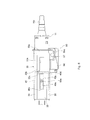
- the steering apparatus for the vehicle 10 includes an upper tube 11 being moveably mounted in back and forth along an axial direction with a space relative to a lower housing 12 as shown in Fig. 3 .
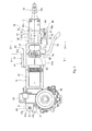
- the lower housing 12 includes a gear housing portion 13, a hollow cylindrical portion 14 and a guide portion 15 and the hollow cylindrical portion 14 and the guide portion 15 are molded with a cast as a whole with these portions as shown in Fig. 1 .
- the hollow cylindrical portion 14 is formed cylindrically over a substantial axial length of the hollow cylindrical portion 14 in order to enforce stiffness of the hollow cylindrical portion 14 more strongly than stiffness of a prior power steering having a hollow cylindrical portion with an undercut portion at a side of a steering lock device, explained hereinafter, to prevent from overlapping with other member. Therefore, the lower housing 12 has the hollow cylindrical portion 14 without undercutting at the side of the steering lock device.
- First intermediate shaft 20 and second intermediate shaft 21 are rotatably supported by the gear housing portion 13 at separated positions respectively along the axial direction.
- the first intermediate shaft 20 and the second intermediate shaft 21 are connected to be rotated with each other through a torsion bar 22 and a torque sensor 23 is mounted on the gear housing 13 to detect an amount of relative rotation of the first intermediate shaft 20 and the second intermediate shaft 21.
- a worm wheel gear 24 is fixed to be fitted into the second intermediate shaft 21 and a worm gear 25 is engaged in mesh with the worm wheel gear 24.
- a driving shaft of a driving motor 26 shown in Fig. 1 is connected to the worm gear 25 to transmit torque of the driving motor 26 to the second intermediate shaft 21 through the worm gear 25 and the worm wheel gear 24 in accordance with the torque detected by the torque sensor 23.
- a steering shaft 16 is rotatably supported with the upper tube 11 and the lower housing 12.
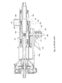
- the steering shaft 16 includes an upper shaft 16a rotatably supported by the upper tube 11 and a lower shaft 16b being movable to the hollow cylindrical portion 14 with a wide space.
- One end of the lower shaft 16b is fit in spline meshing with the upper shaft 16a to be movable in back and forth directions relatively to the upper shaft 16a and to transmit rotation to the upper shaft 16a and the other end of the lower shaft 16b is fixed and fit into the first intermediate shaft 20.
- the lower shaft 16b is rotatably supported through the first intermediate shaft 20 and the upper shaft 16a by the lower housing 12 indirectly.
- To one end of the upper shaft 16a is connected an un-illustrated steering wheel steered by a driver, and an un-illustrated intermediate shaft is connected to one end of the second intermediate shaft 21 opposite to the steering wheel.
- the gear housing portion 13 is supported by an un-illustrated vehicle through a supporting mechanism 80 in lower side and the upper tube 11 is supported to be tilted and moved telescopically relative to the un-illustrated vehicle through a supporting mechanism 25 in upper side.
- the supporting mechanism 25 in the upper side includes a guide supporting mechanism 26 guiding and supporting the upper tube 11 to be tilted and moved telescopically relative to the un-illustrated vehicle, and a lock mechanism 60 locking the upper tube 11 at a position adjusted to be tilted and moved telescopically relative to the un-illustrated vehicle.
- the supporting mechanism 80 at lower side includes a pivot connecting portion 13a formed as a unit with the gear housing portion 13, a bush 81 being fit into a mounting hole 13b of the pivot connecting portion 13a, an un-illustrated shaft supporting pin being fit rotatably into the connecting hole 81a of the bush 81, and an un-illustrated pivot bracket fixed to the un-illustrated vehicle to fix the shaft supporting pin.
- the gear housing 13 is pivotally supported around an axis P of the shaft supporting pin.
- the guide supporting mechanism 26 includes a guide bracket 30, with a shape of letter C in cross section, fixed by a welding etc to a peripheral surface of the upper tube 11, a collapse plate 40 disposed between the upper tube 11 and the guide bracket 30, a mounting bracket 41 fixed to the vehicle, and the guide portion 15 of the lower housing 12 interposed between the mounting bracket 41 and the guide bracket 30 as shown in Fig. 4 .
- the guide bracket 30 is formed by punching and bending from one piece of a plate and includes a pair of first board portions 31, 32 extending to a side of the upper tube 11, guide portions 34, 35 inclining relative to the first board portions 31, 32, and a connecting portion 33 connecting the guide portions 34, 35 each other.
- One ends of the first board portions 31, 32 are fixed respectively to the upper tube 11 by welding etc.
- the guide portions 34, 35 are mounted between the pair of first board portions 31, 32 and the connecting portion 33 and inclined relative to the board portions 31, 32 and the connecting portion 33. As shown in Fig.
- a guide groove 33a for collapse along its axial direction is formed a groove 33b for forming a collapse projection 33c with a shape of a letter L to be communicated to the guide groove 33a for collapse.
- the collapse projection 33c is therefore formed by the groove 33b and a part of collapse projection 33c and a part of the collapse projection 33c is projected into the guide groove 33a for collapse.
- the collapse plate 40 is approximately a plate shape formed with a mold as a whole.
- a telescopic groove 40a along the axial direction of the upper tube 11.
- a hub portion 40b is formed as a whole around a peripheral portion of the telescopic groove 40a of the collapse plate 40 to engage with the guide groove 33a.
- An end 40c of the hub portion 40b at a side of the intermediate shaft engages with an end of the guide groove 33a at a side of the intermediate shaft and an end 40d of the hub portion 40b at a side of the steering wheel engages with the collapse projection 33c.
- a position of the collapse plate 40 is maintained in a position shown in Fig. 6 to be moved with the guide bracket 30 at telescopic regulation until secondary collision occurs.
- the collapse projection 33c is bended to a side of the groove 33b in order to absorb shocked energy and the hub portion 40b is moved to the steering wheel along the groove 33a.
- the mounting bracket 41 is molded with a cast as a whole as shown in Fig. 1 .
- the mounting bracket 41 includes a mounting portion 41a extending along a horizontal direction, one end of which is fixed to the vehicle, and a box portion 41b with a box shape formed at the other end of the mounting portion 41a as a whole.
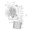
- a tilting groove 41c is formed in the box portion 41b around the axis P shown in Fig. 2 .
- the lock mechanism 60 includes a tightening bolt 63, a pair of plate cams 71, 72 fitted into the tightening bolt 63, a lever 73 rotated with the plate cam 71, and a nut 74 engaged in mesh with a screw portion 63d of the tightening bolt 63 as shown in Fig. 7 .
- the tightening bolt 63 includes a shaft portion 63a, a head portion 63b projected out in radial direction at one end of the shaft portion 63a, and the screw portion 63d at the other end of the shaft portion 63a.
- the shaft portion 63a, the head portion 63b and the screw portion 63d are formed as a whole by cutting etc.
- the pair of plate cams 71, 72 has respectively a cam portion at a faced end each other so that each of the plate cams 71, 72 is approaching or separating each other along its axial direction by the cam portions at relative rotation of each of the plate cams 71, 72.
- a hub portion 72a of the plate cam 72 is inserted into the tilting groove 41c according to the operation of the cam portions, and a flange portion 72b of the plate cam 72 is thereby engaged with an un-illustrated groove of the first plate portion 41 of the adjusting bracket 40 to restrict the rotation of the plate cam 72.
- the guide portion 15 has a shape of letter C in section and includes projecting portions 15a, 15b disposed as a shape intending to grip the guide bracket 30, and plate portion 15c connecting the projecting portions 15a, 15b as shown in Fig. 1 and Fig. 7 .
- Rails 65, 66 are mounted on the projecting portion 15a, 15b to guide and support the guide bracket 30 along the axial direction of the upper tube 11 as shown in Fig. 7 .
- a penetrated hole 15d is formed in the plate 15c to be penetrated by the tightening bolt 63.
- a steering lock device 90 is fixed at the outer peripheral portion of the upper tube 11 to lock and un-lock a rotation of the upper shaft 16 as shown in Fig. 3 and Fig. 5 .
- the steering lock device 90 includes a collar 91 pressed and fit into the upper shaft 16a, a cylinder 92 engaging with a key groove 91 a of the collar 91 in a rotational direction, an actuator 93 operating to insert and separate the cylinder 92 in and from the key groove 91 a, a lock housing 94 guiding the cylinder 92 movable back and forth, a lock bracket portion 95 disposed in a shape intending to grasp the upper tube 11 by the lock housing 94 therewith, and a lock device 96 fixing the lock bracket portion 95 to the lock housing 94.
- the collar 91 forms a plurality of key grooves 91a disposed with equal distance each other along a circumferential direction.
- the actuator 93 for the cylinder includes an un-illustrated motor fixed to the lock housing 94, a worm gear 93a connected to a driving shaft of the un-illustrated motor as a whole, a worm wheel gear 93b engaging in mesh with the worm gear 93a, a rotating shaft 93c connected rotatably with the worm wheel gear 93a and supported rotatably by the lock housing 94, a male screw portion 93d formed in the rotating shaft 93c, a female screw portion 93e engaged in mesh with the male screw portion 93d, a movable member 93f formed the female screw portion 93e and guided and supported movably by the lock housing 94, and a push spring 93g disposed between the cylinder 92 and the movable member 93f.
- an engaging surface 94c having a circular portion in section and engaging to outer peripheral surface of the upper tube 11.
- a hub portion 94d On a surface of the lock housing 94 at a side of the upper tube 11 is formed a hub portion 94d around a circumferential surface of the cylinder 92 as a shape projecting to a side of the upper tube 11 from the engaging surface 94c.
- the hub portion 94 is fit into the penetrating hole 11a formed in the upper tube 11.
- the lock housing 94 is locked its moving along the rotational and axial directions in relative to the upper tube 11 by engaging the hub portion 94 with the penetrating hole 11a.
- the cylinder 92 has a small diameter portion 92a and the small diameter portion 92a is inserted into an un-illustrated penetrated hole of the movable member 93f.
- One end of the small diameter portion 92a has an un-illustrated screw portion engaged and fixed in mesh with the nut 93h.
- the push spring 93g is inserted between a step portion 92b of the cylinder 92 and the movable member 93f.
- the lock bracket portion 95 includes a circular portion 95a engaging with an outer circumferential surface of the upper tube 11, a loop portion 95b bended in a circular shape at one end of the circular portion 95a, and an abutting portion 95c being able to abut to the lock housing 94 at the other end of the circular portion 95a.
- the circular portion 95a of the lock bracket portion 95 is a part of the guide bracket 30 as best shown in Fig. 3 , that is to say the lock bracket portion 95 and the guide bracket 30 are made by one piece as a whole, thereby reducing a number of the parts constructing the steering apparatus of the present invention.
- In the abutting portion 95c is formed a penetrating hole 95d being penetrated by a locking volt 97 described hereinafter.
- a lock cover 94a is fixed to the lock housing 94 to cover over a portion of the lock housing 94.
- a screw hole 94b is formed in the lock housing 94 at a position relative to the penetrating hole 95
- the locking device 96 includes a shaft supporting pin 96a fixed to the lock cover 94a, the loop portion 95b surrounding the shaft supporting pin 96a, the lock bolt 97 engaging in mesh with the screw hole 94b of the lock housing 94 through the penetrating hole 95d of the lock bracket portion 95 as shown in Fig. 1 and Fig. 5 .
- the shaft supporting pin 96a has a head portion 96b projected in radial direction at one its end in order to prevent the shaft supporting pin 96a from loosing against the lock cover 94a by mounting the un-illustrated lock pin or the lock loop to the other end of the shaft supporting pin 96a after the shaft supporting pin 96a is inserted into the lock bracket 95 and the loop portion 95b.
- the engaging surface 94c of the lock housing 94 is abutted to the circumferential surface of the upper tube 11 and the hub portion 94d is fit to the penetrating hole 11a.
- the shaft supporting pin 95a is inserted to the lock cover 94a and the loop portion 95b and the un-illustrated lock pin or lock loop is mounted to the other end of the shaft supporting pin 96.
- the lock bolt 97 is inserted into the penetrating hole 95d and the lock bolt 97 is engaged in mesh with the screw hole 94b.
- the lock housing 94 is locked to the upper tube 11 in a shape that the upper tube 11 is grasped by the lock bracket portion 95 and the lock housing 94.
- the worm gear 93a is rotated by the un-illustrated motor to locking direction.
- the rotation of the worm gear 93a is transformed to axial movement of the movable member 93f through the worm wheel gear 93b, the male screw portion 93d and the female screw portion 93e.
- the movable member 93f is moved to a side of the upper tube 11 along the axial direction and the cylinder 92 is pressed to be entered into the key groove 91a by the press spring 93g. If the cylinder 92 is not inserted into the key groove 91a, the upper shaft 16a is rotated by the steering wheel to engage the cylinder 92 into the key groove 91a surely, thereby locking the rotation of the upper shaft 16a.
- the worm gear 93a is rotated by the un-illustrated motor to unlocking direction.
- the movable member 93f is moved to opposite side of the upper tube 11 along the axial direction and the cylinder 92 is retracted to opposite side of the upper tube 11 through nut 93h.
- the cylinder 92 is unlocked from the key groove 91a to allow the rotation of the upper shaft 16a.
- the plate cams 71, 72 are moved to be separated each other to increase the force pressing the collapse plate 40 and the guide bracket 30 to the guide portion 15, thereby increasing the force to press the guide portion 15 to the box portion 41b. Thereby, the upper tube 11 is locked against the bracket 41 at the desired telescopic and tilting positions.
- the mounting bracket 41, the lock housing 94 and the collapse plate 40 are molded with the cast and it is constructed that the guide portion 15 is pressed to the box portion 41b in one direction and the collapse plate 40 and the guide bracket 30 are pressed to the guide portion 15 in one direction, there is a quite small noise based on the bracket's interference at the steering wheel operation in comparison with the prior art that the distance bracket and the adjusting bracket are made with the steel plate and the distance bracket with the letter C shape grasps the adjust bracket with the letter C shape from both sides.
- the hollow cylindrical portion 14 of the lower housing 12 is formed cylindrically over the substantial axial length of the hollow cylindrical portion 14 in order to enforce stiffness of the hollow cylindrical portion 14 more strongly than stiffness of the prior steering apparatus for the vehicle having the hollow cylindrical portion with the undercut portion at the side of the steering lock device to prevent from overlapping with other member.
- the lower housing 12 has the hollow cylindrical portion 14 without undercutting at the side of the steering lock device.
- one embodiment of the present invention has the construction that the cylinder 92 and the movable member 93f are mounted in parallel and the rotation is transferred to the axial movement by the male screw portion 93d and the female screw portion 93e, however it is not restricted to the construction but it may have the construction that a hollow cylindrical movable member 93f is mounted on the outer peripheral surface with same axis and the rotation is transferred to the axial movement by a cam mechanism mounted between the cylinder 92 and the movable member 93f.
Landscapes
- Engineering & Computer Science (AREA)
- Mechanical Engineering (AREA)
- Chemical & Material Sciences (AREA)
- Combustion & Propulsion (AREA)
- Transportation (AREA)
- Steering Controls (AREA)
- Lock And Its Accessories (AREA)
Applications Claiming Priority (1)
| Application Number | Priority Date | Filing Date | Title |
|---|---|---|---|
| JP2011054992A JP5750949B2 (ja) | 2011-03-14 | 2011-03-14 | 車両用ステアリング装置 |
Publications (3)
| Publication Number | Publication Date |
|---|---|
| EP2500241A2 true EP2500241A2 (de) | 2012-09-19 |
| EP2500241A3 EP2500241A3 (de) | 2013-03-06 |
| EP2500241B1 EP2500241B1 (de) | 2014-10-29 |
Family
ID=45894112
Family Applications (1)
| Application Number | Title | Priority Date | Filing Date |
|---|---|---|---|
| EP12158631.7A Active EP2500241B1 (de) | 2011-03-14 | 2012-03-08 | Lenkeinrichtung für ein Fahrzeug |
Country Status (3)
| Country | Link |
|---|---|
| US (1) | US8733201B2 (de) |
| EP (1) | EP2500241B1 (de) |
| JP (1) | JP5750949B2 (de) |
Cited By (3)
| Publication number | Priority date | Publication date | Assignee | Title |
|---|---|---|---|---|
| CN104554421A (zh) * | 2014-12-30 | 2015-04-29 | 耐世特汽车系统(苏州)有限公司 | 一种转向管柱护管 |
| US20180251147A1 (en) * | 2015-08-26 | 2018-09-06 | Thyssenkrupp Presta Ag | Motor-adjustable steering column for a motor vehicle |
| US20230055548A1 (en) * | 2020-02-25 | 2023-02-23 | Mando Corporation | Steering column for vehicle |
Families Citing this family (20)
| Publication number | Priority date | Publication date | Assignee | Title |
|---|---|---|---|---|
| JP5999767B2 (ja) * | 2012-12-27 | 2016-09-28 | 株式会社ジェイテクト | ステアリング装置 |
| FR3025161B1 (fr) * | 2014-08-29 | 2016-12-30 | Zf Systemes De Direction Nacam Sas | Mecanisme de colonne de direction ajustable a verrou antivol |
| JP2016055689A (ja) * | 2014-09-08 | 2016-04-21 | 富士機工株式会社 | 電動式ステアリングコラム装置 |
| KR102190492B1 (ko) * | 2015-03-02 | 2020-12-14 | 주식회사 만도 | 자동차의 조향컬럼 |
| US11560169B2 (en) | 2015-06-11 | 2023-01-24 | Steering Solutions Ip Holding Corporation | Retractable steering column system and method |
| US10343706B2 (en) | 2015-06-11 | 2019-07-09 | Steering Solutions Ip Holding Corporation | Retractable steering column system, vehicle having the same, and method |
| US10577009B2 (en) | 2015-06-16 | 2020-03-03 | Steering Solutions Ip Holding Corporation | Retractable steering column assembly and method |
| DE102016111473A1 (de) | 2015-06-25 | 2016-12-29 | Steering Solutions Ip Holding Corporation | Stationäre lenkradbaugruppe und verfahren |
| DE102016205378B3 (de) * | 2016-03-31 | 2017-05-11 | Thyssenkrupp Ag | Lenksäule für ein Kraftfahrzeug |
| CN107521547B (zh) | 2016-06-21 | 2020-03-10 | 操纵技术Ip控股公司 | 转向柱组件的自锁伸缩式致动器 |
| US10457313B2 (en) | 2016-06-28 | 2019-10-29 | Steering Solutions Ip Holding Corporation | ADAS wheel locking device |
| US10363958B2 (en) | 2016-07-26 | 2019-07-30 | Steering Solutions Ip Holding Corporation | Electric power steering mode determination and transitioning |
| US10189496B2 (en) | 2016-08-22 | 2019-01-29 | Steering Solutions Ip Holding Corporation | Steering assembly having a telescope drive lock assembly |
| US20180086378A1 (en) * | 2016-09-27 | 2018-03-29 | Steering Solutions Ip Holding Corporation | Position detection system for a retractable steering column |
| US10351160B2 (en) | 2016-11-30 | 2019-07-16 | Steering Solutions Ip Holding Corporation | Steering column assembly having a sensor assembly |
| US10370022B2 (en) | 2017-02-13 | 2019-08-06 | Steering Solutions Ip Holding Corporation | Steering column assembly for autonomous vehicle |
| US10385930B2 (en) | 2017-02-21 | 2019-08-20 | Steering Solutions Ip Holding Corporation | Ball coupling assembly for steering column assembly |
| DE102017120669A1 (de) * | 2017-09-07 | 2019-03-07 | Trw Automotive Gmbh | Lenksäulenbaugruppe für ein Kraftfahrzeug sowie Lenkungssystem |
| US10974756B2 (en) | 2018-07-31 | 2021-04-13 | Steering Solutions Ip Holding Corporation | Clutch device latching system and method |
| DE102020201703A1 (de) * | 2020-02-11 | 2021-08-12 | Thyssenkrupp Ag | Lenksäule für ein Kraftfahrzeug |
Citations (1)
| Publication number | Priority date | Publication date | Assignee | Title |
|---|---|---|---|---|
| US20050029795A1 (en) | 2001-10-23 | 2005-02-10 | Camp Eckart Op Den | Vehicle steering assembly |
Family Cites Families (16)
| Publication number | Priority date | Publication date | Assignee | Title |
|---|---|---|---|---|
| DE4038010A1 (de) * | 1990-11-29 | 1992-06-04 | Stabilus Gmbh | Hydraulisch verstellbare lenksaeule |
| US5485376A (en) * | 1991-06-14 | 1996-01-16 | Nissan Motor Co., Ltd. | Steering wheel posture control system |
| DE4436091C1 (de) | 1994-10-10 | 1996-02-22 | Kostal Leopold Gmbh & Co Kg | Lenkvorrichtung für Kraftfahrzeuge |
| US5718132A (en) * | 1996-08-05 | 1998-02-17 | General Motors Corporation | Anti-theft steering shaft lock |
| US5992191A (en) * | 1998-04-06 | 1999-11-30 | Nickeas; Mark | Anti-theft device for motor vehicles |
| DE20103203U1 (de) * | 2001-02-23 | 2001-07-05 | Huf Huelsbeck & Fuerst Gmbh | Vorrichtung zum fallweisen Sperren einer Lenksäule in einem Fahrzeug |
| JP2003327134A (ja) * | 2002-05-09 | 2003-11-19 | Koyo Seiko Co Ltd | 衝撃吸収式ステアリング装置 |
| JP2005297645A (ja) * | 2004-04-07 | 2005-10-27 | Tokai Rika Co Ltd | ステアリングロック装置 |
| JP2007099260A (ja) * | 2005-07-11 | 2007-04-19 | Nsk Ltd | ステアリング装置 |
| JP4483931B2 (ja) * | 2007-11-08 | 2010-06-16 | トヨタ自動車株式会社 | ステアリング装置 |
| US8596160B2 (en) * | 2007-11-13 | 2013-12-03 | Nsk Ltd. | Steering apparatus |
| JP5358932B2 (ja) * | 2007-11-13 | 2013-12-04 | 日本精工株式会社 | ステアリング装置 |
| JP5229551B2 (ja) * | 2008-08-29 | 2013-07-03 | 株式会社ジェイテクト | 車両用操舵装置 |
| FR2937598B1 (fr) | 2008-10-23 | 2011-09-23 | Valeo Securite Habitacle | Dispositif antivol pour colonne de direction de vehicule automobile |
| CN102256858B (zh) | 2008-12-19 | 2014-12-10 | C.劳勃.汉默斯坦两合有限公司 | 具有支撑部和转向柱的用于机动车辆的长度可调节的转向致动单元 |
| US8272291B2 (en) * | 2010-01-15 | 2012-09-25 | Samuel Fasone | Steering column locking device |
-
2011
- 2011-03-14 JP JP2011054992A patent/JP5750949B2/ja active Active
-
2012
- 2012-03-06 US US13/413,088 patent/US8733201B2/en active Active
- 2012-03-08 EP EP12158631.7A patent/EP2500241B1/de active Active
Patent Citations (1)
| Publication number | Priority date | Publication date | Assignee | Title |
|---|---|---|---|---|
| US20050029795A1 (en) | 2001-10-23 | 2005-02-10 | Camp Eckart Op Den | Vehicle steering assembly |
Cited By (4)
| Publication number | Priority date | Publication date | Assignee | Title |
|---|---|---|---|---|
| CN104554421A (zh) * | 2014-12-30 | 2015-04-29 | 耐世特汽车系统(苏州)有限公司 | 一种转向管柱护管 |
| US20180251147A1 (en) * | 2015-08-26 | 2018-09-06 | Thyssenkrupp Presta Ag | Motor-adjustable steering column for a motor vehicle |
| US20230055548A1 (en) * | 2020-02-25 | 2023-02-23 | Mando Corporation | Steering column for vehicle |
| US11753063B2 (en) * | 2020-02-25 | 2023-09-12 | Hl Mando Corporation | Steering column for vehicle |
Also Published As
| Publication number | Publication date |
|---|---|
| EP2500241B1 (de) | 2014-10-29 |
| US20120234127A1 (en) | 2012-09-20 |
| EP2500241A3 (de) | 2013-03-06 |
| JP2012188055A (ja) | 2012-10-04 |
| US8733201B2 (en) | 2014-05-27 |
| JP5750949B2 (ja) | 2015-07-22 |
Similar Documents
| Publication | Publication Date | Title |
|---|---|---|
| EP2500241B1 (de) | Lenkeinrichtung für ein Fahrzeug | |
| EP2923919B1 (de) | Lenkvorrichtung | |
| EP2195221B1 (de) | Klemmvorrichtung für eine lenksäulenanordnung | |
| EP1975036B1 (de) | Sperrmechanismus für eine einstellbare Lenksäulenanordnung | |
| US9545943B2 (en) | Steering device | |
| EP2923921B1 (de) | Lenkvorrichtung | |
| EP1762462B1 (de) | Lenkeinrichtung | |
| US9032834B2 (en) | Steering device | |
| EP1919756B1 (de) | Lenksäulenanordnung | |
| US10919562B2 (en) | Steering assembly with positive lock and energy absorption and pyrotechnic actuator | |
| EP2602170B1 (de) | Lenkvorrichtung | |
| JP2008174105A (ja) | ステアリング装置 | |
| CN108528518B (zh) | 转向装置 | |
| JP4985443B2 (ja) | ステアリングコラム装置 | |
| CN108528517B (zh) | 转向装置 | |
| JP5267528B2 (ja) | 衝撃吸収式ステアリング装置 | |
| JP2009119999A (ja) | 車両用ステアリングコラム装置 | |
| WO2005102818A1 (en) | Improved steering column assembly | |
| JP2008126750A (ja) | ステアリング装置 | |
| JP2022189047A (ja) | ステアリング装置 | |
| JP3582368B2 (ja) | ステアリング装置 | |
| EP4017782B1 (de) | Formschlüssige arretierung einer teleskopischen lenksäule und anfahrsicherung | |
| JP6536888B2 (ja) | ステアリング装置 | |
| JP4185396B2 (ja) | ステアリングコラム装置 | |
| CN116729468A (zh) | 转向装置 |
Legal Events
| Date | Code | Title | Description |
|---|---|---|---|
| PUAI | Public reference made under article 153(3) epc to a published international application that has entered the european phase |
Free format text: ORIGINAL CODE: 0009012 |
|
| AK | Designated contracting states |
Kind code of ref document: A2 Designated state(s): AL AT BE BG CH CY CZ DE DK EE ES FI FR GB GR HR HU IE IS IT LI LT LU LV MC MK MT NL NO PL PT RO RS SE SI SK SM TR |
|
| AX | Request for extension of the european patent |
Extension state: BA ME |
|
| PUAL | Search report despatched |
Free format text: ORIGINAL CODE: 0009013 |
|
| AK | Designated contracting states |
Kind code of ref document: A3 Designated state(s): AL AT BE BG CH CY CZ DE DK EE ES FI FR GB GR HR HU IE IS IT LI LT LU LV MC MK MT NL NO PL PT RO RS SE SI SK SM TR |
|
| AX | Request for extension of the european patent |
Extension state: BA ME |
|
| RIC1 | Information provided on ipc code assigned before grant |
Ipc: B62D 1/184 20060101ALI20130130BHEP Ipc: B60R 25/02 20130101ALI20130130BHEP Ipc: B62D 1/185 20060101AFI20130130BHEP |
|
| 17P | Request for examination filed |
Effective date: 20130826 |
|
| RBV | Designated contracting states (corrected) |
Designated state(s): AL AT BE BG CH CY CZ DE DK EE ES FI FR GB GR HR HU IE IS IT LI LT LU LV MC MK MT NL NO PL PT RO RS SE SI SK SM TR |
|
| GRAP | Despatch of communication of intention to grant a patent |
Free format text: ORIGINAL CODE: EPIDOSNIGR1 |
|
| INTG | Intention to grant announced |
Effective date: 20140416 |
|
| GRAS | Grant fee paid |
Free format text: ORIGINAL CODE: EPIDOSNIGR3 |
|
| GRAA | (expected) grant |
Free format text: ORIGINAL CODE: 0009210 |
|
| RIN1 | Information on inventor provided before grant (corrected) |
Inventor name: OSUKA, AKIO Inventor name: OKANO, RYOTA |
|
| AK | Designated contracting states |
Kind code of ref document: B1 Designated state(s): AL AT BE BG CH CY CZ DE DK EE ES FI FR GB GR HR HU IE IS IT LI LT LU LV MC MK MT NL NO PL PT RO RS SE SI SK SM TR |
|
| REG | Reference to a national code |
Ref country code: GB Ref legal event code: FG4D |
|
| REG | Reference to a national code |
Ref country code: CH Ref legal event code: EP |
|
| REG | Reference to a national code |
Ref country code: AT Ref legal event code: REF Ref document number: 693419 Country of ref document: AT Kind code of ref document: T Effective date: 20141115 |
|
| REG | Reference to a national code |
Ref country code: IE Ref legal event code: FG4D |
|
| REG | Reference to a national code |
Ref country code: DE Ref legal event code: R096 Ref document number: 602012003536 Country of ref document: DE Effective date: 20141204 |
|
| REG | Reference to a national code |
Ref country code: AT Ref legal event code: MK05 Ref document number: 693419 Country of ref document: AT Kind code of ref document: T Effective date: 20141029 |
|
| REG | Reference to a national code |
Ref country code: NL Ref legal event code: VDEP Effective date: 20141029 |
|
| REG | Reference to a national code |
Ref country code: LT Ref legal event code: MG4D |
|
| PG25 | Lapsed in a contracting state [announced via postgrant information from national office to epo] |
Ref country code: IS Free format text: LAPSE BECAUSE OF FAILURE TO SUBMIT A TRANSLATION OF THE DESCRIPTION OR TO PAY THE FEE WITHIN THE PRESCRIBED TIME-LIMIT Effective date: 20150228 Ref country code: FI Free format text: LAPSE BECAUSE OF FAILURE TO SUBMIT A TRANSLATION OF THE DESCRIPTION OR TO PAY THE FEE WITHIN THE PRESCRIBED TIME-LIMIT Effective date: 20141029 Ref country code: ES Free format text: LAPSE BECAUSE OF FAILURE TO SUBMIT A TRANSLATION OF THE DESCRIPTION OR TO PAY THE FEE WITHIN THE PRESCRIBED TIME-LIMIT Effective date: 20141029 Ref country code: PT Free format text: LAPSE BECAUSE OF FAILURE TO SUBMIT A TRANSLATION OF THE DESCRIPTION OR TO PAY THE FEE WITHIN THE PRESCRIBED TIME-LIMIT Effective date: 20150302 Ref country code: NO Free format text: LAPSE BECAUSE OF FAILURE TO SUBMIT A TRANSLATION OF THE DESCRIPTION OR TO PAY THE FEE WITHIN THE PRESCRIBED TIME-LIMIT Effective date: 20150129 Ref country code: NL Free format text: LAPSE BECAUSE OF FAILURE TO SUBMIT A TRANSLATION OF THE DESCRIPTION OR TO PAY THE FEE WITHIN THE PRESCRIBED TIME-LIMIT Effective date: 20141029 Ref country code: LT Free format text: LAPSE BECAUSE OF FAILURE TO SUBMIT A TRANSLATION OF THE DESCRIPTION OR TO PAY THE FEE WITHIN THE PRESCRIBED TIME-LIMIT Effective date: 20141029 |
|
| PG25 | Lapsed in a contracting state [announced via postgrant information from national office to epo] |
Ref country code: PL Free format text: LAPSE BECAUSE OF FAILURE TO SUBMIT A TRANSLATION OF THE DESCRIPTION OR TO PAY THE FEE WITHIN THE PRESCRIBED TIME-LIMIT Effective date: 20141029 Ref country code: RS Free format text: LAPSE BECAUSE OF FAILURE TO SUBMIT A TRANSLATION OF THE DESCRIPTION OR TO PAY THE FEE WITHIN THE PRESCRIBED TIME-LIMIT Effective date: 20141029 Ref country code: HR Free format text: LAPSE BECAUSE OF FAILURE TO SUBMIT A TRANSLATION OF THE DESCRIPTION OR TO PAY THE FEE WITHIN THE PRESCRIBED TIME-LIMIT Effective date: 20141029 Ref country code: AT Free format text: LAPSE BECAUSE OF FAILURE TO SUBMIT A TRANSLATION OF THE DESCRIPTION OR TO PAY THE FEE WITHIN THE PRESCRIBED TIME-LIMIT Effective date: 20141029 Ref country code: LV Free format text: LAPSE BECAUSE OF FAILURE TO SUBMIT A TRANSLATION OF THE DESCRIPTION OR TO PAY THE FEE WITHIN THE PRESCRIBED TIME-LIMIT Effective date: 20141029 Ref country code: SE Free format text: LAPSE BECAUSE OF FAILURE TO SUBMIT A TRANSLATION OF THE DESCRIPTION OR TO PAY THE FEE WITHIN THE PRESCRIBED TIME-LIMIT Effective date: 20141029 Ref country code: GR Free format text: LAPSE BECAUSE OF FAILURE TO SUBMIT A TRANSLATION OF THE DESCRIPTION OR TO PAY THE FEE WITHIN THE PRESCRIBED TIME-LIMIT Effective date: 20150130 Ref country code: CY Free format text: LAPSE BECAUSE OF FAILURE TO SUBMIT A TRANSLATION OF THE DESCRIPTION OR TO PAY THE FEE WITHIN THE PRESCRIBED TIME-LIMIT Effective date: 20141029 |
|
| REG | Reference to a national code |
Ref country code: DE Ref legal event code: R097 Ref document number: 602012003536 Country of ref document: DE |
|
| PG25 | Lapsed in a contracting state [announced via postgrant information from national office to epo] |
Ref country code: DK Free format text: LAPSE BECAUSE OF FAILURE TO SUBMIT A TRANSLATION OF THE DESCRIPTION OR TO PAY THE FEE WITHIN THE PRESCRIBED TIME-LIMIT Effective date: 20141029 Ref country code: EE Free format text: LAPSE BECAUSE OF FAILURE TO SUBMIT A TRANSLATION OF THE DESCRIPTION OR TO PAY THE FEE WITHIN THE PRESCRIBED TIME-LIMIT Effective date: 20141029 Ref country code: RO Free format text: LAPSE BECAUSE OF FAILURE TO SUBMIT A TRANSLATION OF THE DESCRIPTION OR TO PAY THE FEE WITHIN THE PRESCRIBED TIME-LIMIT Effective date: 20141029 Ref country code: SK Free format text: LAPSE BECAUSE OF FAILURE TO SUBMIT A TRANSLATION OF THE DESCRIPTION OR TO PAY THE FEE WITHIN THE PRESCRIBED TIME-LIMIT Effective date: 20141029 Ref country code: CZ Free format text: LAPSE BECAUSE OF FAILURE TO SUBMIT A TRANSLATION OF THE DESCRIPTION OR TO PAY THE FEE WITHIN THE PRESCRIBED TIME-LIMIT Effective date: 20141029 |
|
| PG25 | Lapsed in a contracting state [announced via postgrant information from national office to epo] |
Ref country code: IT Free format text: LAPSE BECAUSE OF FAILURE TO SUBMIT A TRANSLATION OF THE DESCRIPTION OR TO PAY THE FEE WITHIN THE PRESCRIBED TIME-LIMIT Effective date: 20141029 |
|
| PLBE | No opposition filed within time limit |
Free format text: ORIGINAL CODE: 0009261 |
|
| STAA | Information on the status of an ep patent application or granted ep patent |
Free format text: STATUS: NO OPPOSITION FILED WITHIN TIME LIMIT |
|
| 26N | No opposition filed |
Effective date: 20150730 |
|
| PG25 | Lapsed in a contracting state [announced via postgrant information from national office to epo] |
Ref country code: LU Free format text: LAPSE BECAUSE OF FAILURE TO SUBMIT A TRANSLATION OF THE DESCRIPTION OR TO PAY THE FEE WITHIN THE PRESCRIBED TIME-LIMIT Effective date: 20150308 Ref country code: MC Free format text: LAPSE BECAUSE OF FAILURE TO SUBMIT A TRANSLATION OF THE DESCRIPTION OR TO PAY THE FEE WITHIN THE PRESCRIBED TIME-LIMIT Effective date: 20141029 |
|
| REG | Reference to a national code |
Ref country code: CH Ref legal event code: PL |
|
| REG | Reference to a national code |
Ref country code: IE Ref legal event code: MM4A |
|
| PG25 | Lapsed in a contracting state [announced via postgrant information from national office to epo] |
Ref country code: CH Free format text: LAPSE BECAUSE OF NON-PAYMENT OF DUE FEES Effective date: 20150331 Ref country code: IE Free format text: LAPSE BECAUSE OF NON-PAYMENT OF DUE FEES Effective date: 20150308 Ref country code: LI Free format text: LAPSE BECAUSE OF NON-PAYMENT OF DUE FEES Effective date: 20150331 |
|
| REG | Reference to a national code |
Ref country code: FR Ref legal event code: PLFP Year of fee payment: 5 |
|
| PG25 | Lapsed in a contracting state [announced via postgrant information from national office to epo] |
Ref country code: SI Free format text: LAPSE BECAUSE OF FAILURE TO SUBMIT A TRANSLATION OF THE DESCRIPTION OR TO PAY THE FEE WITHIN THE PRESCRIBED TIME-LIMIT Effective date: 20141029 |
|
| GBPC | Gb: european patent ceased through non-payment of renewal fee |
Effective date: 20160308 |
|
| PG25 | Lapsed in a contracting state [announced via postgrant information from national office to epo] |
Ref country code: MT Free format text: LAPSE BECAUSE OF FAILURE TO SUBMIT A TRANSLATION OF THE DESCRIPTION OR TO PAY THE FEE WITHIN THE PRESCRIBED TIME-LIMIT Effective date: 20141029 |
|
| PG25 | Lapsed in a contracting state [announced via postgrant information from national office to epo] |
Ref country code: GB Free format text: LAPSE BECAUSE OF NON-PAYMENT OF DUE FEES Effective date: 20160308 |
|
| REG | Reference to a national code |
Ref country code: FR Ref legal event code: PLFP Year of fee payment: 6 |
|
| PG25 | Lapsed in a contracting state [announced via postgrant information from national office to epo] |
Ref country code: HU Free format text: LAPSE BECAUSE OF FAILURE TO SUBMIT A TRANSLATION OF THE DESCRIPTION OR TO PAY THE FEE WITHIN THE PRESCRIBED TIME-LIMIT; INVALID AB INITIO Effective date: 20120308 Ref country code: BG Free format text: LAPSE BECAUSE OF FAILURE TO SUBMIT A TRANSLATION OF THE DESCRIPTION OR TO PAY THE FEE WITHIN THE PRESCRIBED TIME-LIMIT Effective date: 20141029 Ref country code: SM Free format text: LAPSE BECAUSE OF FAILURE TO SUBMIT A TRANSLATION OF THE DESCRIPTION OR TO PAY THE FEE WITHIN THE PRESCRIBED TIME-LIMIT Effective date: 20141029 |
|
| PG25 | Lapsed in a contracting state [announced via postgrant information from national office to epo] |
Ref country code: TR Free format text: LAPSE BECAUSE OF FAILURE TO SUBMIT A TRANSLATION OF THE DESCRIPTION OR TO PAY THE FEE WITHIN THE PRESCRIBED TIME-LIMIT Effective date: 20141029 |
|
| PG25 | Lapsed in a contracting state [announced via postgrant information from national office to epo] |
Ref country code: BE Free format text: LAPSE BECAUSE OF FAILURE TO SUBMIT A TRANSLATION OF THE DESCRIPTION OR TO PAY THE FEE WITHIN THE PRESCRIBED TIME-LIMIT Effective date: 20141029 |
|
| REG | Reference to a national code |
Ref country code: FR Ref legal event code: PLFP Year of fee payment: 7 |
|
| PG25 | Lapsed in a contracting state [announced via postgrant information from national office to epo] |
Ref country code: MK Free format text: LAPSE BECAUSE OF FAILURE TO SUBMIT A TRANSLATION OF THE DESCRIPTION OR TO PAY THE FEE WITHIN THE PRESCRIBED TIME-LIMIT Effective date: 20141029 |
|
| PG25 | Lapsed in a contracting state [announced via postgrant information from national office to epo] |
Ref country code: AL Free format text: LAPSE BECAUSE OF FAILURE TO SUBMIT A TRANSLATION OF THE DESCRIPTION OR TO PAY THE FEE WITHIN THE PRESCRIBED TIME-LIMIT Effective date: 20141029 |
|
| PGFP | Annual fee paid to national office [announced via postgrant information from national office to epo] |
Ref country code: FR Payment date: 20230208 Year of fee payment: 12 |
|
| PGFP | Annual fee paid to national office [announced via postgrant information from national office to epo] |
Ref country code: DE Payment date: 20240130 Year of fee payment: 13 |