EP2500114B1 - Kaltwalzmaschine und kaltwalzverfahren - Google Patents
Kaltwalzmaschine und kaltwalzverfahren Download PDFInfo
- Publication number
- EP2500114B1 EP2500114B1 EP09851110.8A EP09851110A EP2500114B1 EP 2500114 B1 EP2500114 B1 EP 2500114B1 EP 09851110 A EP09851110 A EP 09851110A EP 2500114 B1 EP2500114 B1 EP 2500114B1
- Authority
- EP
- European Patent Office
- Prior art keywords
- coil
- cold rolling
- strip
- winding
- joining
- Prior art date
- Legal status (The legal status is an assumption and is not a legal conclusion. Google has not performed a legal analysis and makes no representation as to the accuracy of the status listed.)
- Active
Links
- 238000005097 cold rolling Methods 0.000 title claims description 348
- 238000000034 method Methods 0.000 title claims description 87
- 238000005096 rolling process Methods 0.000 claims description 405
- 238000004804 winding Methods 0.000 claims description 319
- 238000005304 joining Methods 0.000 claims description 179
- 238000005520 cutting process Methods 0.000 claims description 146
- 230000002441 reversible effect Effects 0.000 claims description 126
- 238000003466 welding Methods 0.000 claims description 35
- 230000009467 reduction Effects 0.000 claims description 34
- 238000003860 storage Methods 0.000 claims description 33
- 230000007246 mechanism Effects 0.000 claims description 13
- 239000002826 coolant Substances 0.000 claims description 8
- 230000003247 decreasing effect Effects 0.000 claims description 3
- 239000000463 material Substances 0.000 description 53
- 238000004519 manufacturing process Methods 0.000 description 28
- 238000002360 preparation method Methods 0.000 description 18
- 230000000694 effects Effects 0.000 description 15
- 238000010008 shearing Methods 0.000 description 13
- 238000003825 pressing Methods 0.000 description 12
- 239000007787 solid Substances 0.000 description 11
- 238000011144 upstream manufacturing Methods 0.000 description 7
- 230000001133 acceleration Effects 0.000 description 5
- 230000002950 deficient Effects 0.000 description 5
- 238000010438 heat treatment Methods 0.000 description 5
- 239000002184 metal Substances 0.000 description 5
- 230000015572 biosynthetic process Effects 0.000 description 4
- 230000007547 defect Effects 0.000 description 4
- 239000000284 extract Substances 0.000 description 4
- 230000008569 process Effects 0.000 description 4
- 238000010586 diagram Methods 0.000 description 3
- YKCSYIYQRSVLAK-UHFFFAOYSA-N 3,5-dimethyl-2-phenylmorpholine Chemical compound CC1NC(C)COC1C1=CC=CC=C1 YKCSYIYQRSVLAK-UHFFFAOYSA-N 0.000 description 2
- 230000008859 change Effects 0.000 description 2
- 238000010422 painting Methods 0.000 description 2
- 229910000831 Steel Inorganic materials 0.000 description 1
- 230000009471 action Effects 0.000 description 1
- 238000013459 approach Methods 0.000 description 1
- 239000010960 cold rolled steel Substances 0.000 description 1
- 230000001143 conditioned effect Effects 0.000 description 1
- 230000007423 decrease Effects 0.000 description 1
- 238000001514 detection method Methods 0.000 description 1
- 230000002708 enhancing effect Effects 0.000 description 1
- 238000000605 extraction Methods 0.000 description 1
- 239000007769 metal material Substances 0.000 description 1
- 238000003801 milling Methods 0.000 description 1
- 238000005554 pickling Methods 0.000 description 1
- 230000002035 prolonged effect Effects 0.000 description 1
- 238000009877 rendering Methods 0.000 description 1
- 239000010959 steel Substances 0.000 description 1
Images


Classifications
-
- B—PERFORMING OPERATIONS; TRANSPORTING
- B21—MECHANICAL METAL-WORKING WITHOUT ESSENTIALLY REMOVING MATERIAL; PUNCHING METAL
- B21B—ROLLING OF METAL
- B21B1/00—Metal-rolling methods or mills for making semi-finished products of solid or profiled cross-section; Sequence of operations in milling trains; Layout of rolling-mill plant, e.g. grouping of stands; Succession of passes or of sectional pass alternations
- B21B1/22—Metal-rolling methods or mills for making semi-finished products of solid or profiled cross-section; Sequence of operations in milling trains; Layout of rolling-mill plant, e.g. grouping of stands; Succession of passes or of sectional pass alternations for rolling plates, strips, bands or sheets of indefinite length
- B21B1/30—Metal-rolling methods or mills for making semi-finished products of solid or profiled cross-section; Sequence of operations in milling trains; Layout of rolling-mill plant, e.g. grouping of stands; Succession of passes or of sectional pass alternations for rolling plates, strips, bands or sheets of indefinite length in a non-continuous process
- B21B1/32—Metal-rolling methods or mills for making semi-finished products of solid or profiled cross-section; Sequence of operations in milling trains; Layout of rolling-mill plant, e.g. grouping of stands; Succession of passes or of sectional pass alternations for rolling plates, strips, bands or sheets of indefinite length in a non-continuous process in reversing single stand mills, e.g. with intermediate storage reels for accumulating work
- B21B1/36—Metal-rolling methods or mills for making semi-finished products of solid or profiled cross-section; Sequence of operations in milling trains; Layout of rolling-mill plant, e.g. grouping of stands; Succession of passes or of sectional pass alternations for rolling plates, strips, bands or sheets of indefinite length in a non-continuous process in reversing single stand mills, e.g. with intermediate storage reels for accumulating work by cold-rolling
-
- B—PERFORMING OPERATIONS; TRANSPORTING
- B21—MECHANICAL METAL-WORKING WITHOUT ESSENTIALLY REMOVING MATERIAL; PUNCHING METAL
- B21B—ROLLING OF METAL
- B21B15/00—Arrangements for performing additional metal-working operations specially combined with or arranged in, or specially adapted for use in connection with, metal-rolling mills
-
- B—PERFORMING OPERATIONS; TRANSPORTING
- B21—MECHANICAL METAL-WORKING WITHOUT ESSENTIALLY REMOVING MATERIAL; PUNCHING METAL
- B21B—ROLLING OF METAL
- B21B37/00—Control devices or methods specially adapted for metal-rolling mills or the work produced thereby
- B21B37/16—Control of thickness, width, diameter or other transverse dimensions
- B21B37/18—Automatic gauge control
-
- B—PERFORMING OPERATIONS; TRANSPORTING
- B21—MECHANICAL METAL-WORKING WITHOUT ESSENTIALLY REMOVING MATERIAL; PUNCHING METAL
- B21B—ROLLING OF METAL
- B21B37/00—Control devices or methods specially adapted for metal-rolling mills or the work produced thereby
- B21B37/28—Control of flatness or profile during rolling of strip, sheets or plates
- B21B37/30—Control of flatness or profile during rolling of strip, sheets or plates using roll camber control
- B21B37/32—Control of flatness or profile during rolling of strip, sheets or plates using roll camber control by cooling, heating or lubricating the rolls
-
- B—PERFORMING OPERATIONS; TRANSPORTING
- B21—MECHANICAL METAL-WORKING WITHOUT ESSENTIALLY REMOVING MATERIAL; PUNCHING METAL
- B21B—ROLLING OF METAL
- B21B15/00—Arrangements for performing additional metal-working operations specially combined with or arranged in, or specially adapted for use in connection with, metal-rolling mills
- B21B15/0085—Joining ends of material to continuous strip, bar or sheet
-
- B—PERFORMING OPERATIONS; TRANSPORTING
- B21—MECHANICAL METAL-WORKING WITHOUT ESSENTIALLY REMOVING MATERIAL; PUNCHING METAL
- B21B—ROLLING OF METAL
- B21B15/00—Arrangements for performing additional metal-working operations specially combined with or arranged in, or specially adapted for use in connection with, metal-rolling mills
- B21B2015/0057—Coiling the rolled product
-
- B—PERFORMING OPERATIONS; TRANSPORTING
- B21—MECHANICAL METAL-WORKING WITHOUT ESSENTIALLY REMOVING MATERIAL; PUNCHING METAL
- B21B—ROLLING OF METAL
- B21B15/00—Arrangements for performing additional metal-working operations specially combined with or arranged in, or specially adapted for use in connection with, metal-rolling mills
- B21B2015/0064—Uncoiling the rolled product
Definitions
- the present invention relates to cold-rolled material manufacturing equipment and a cold rolling method.
- RCM equipment reversible cold rolling equipment
- RCM equipment As rolling equipment for manufacturing cold-rolled materials of a variety of steels in small amounts of a total of about 300,000 tons of product per year, reversible cold rolling equipment (hereinafter referred to as RCM equipment) has been put to practical use which includes one cold rolling mill and strip winding/unwinding devices disposed respectively on the entry side and the delivery side of the cold rolling mill to be used for both winding and unwinding of strip and in which the strip is put to reversible rolling between the winding/unwinding devices on the entry side and the delivery side of the cold rolling mill, to roll the strip down to a desired strip thickness.
- RCM equipment reversible cold rolling equipment
- the leading end of a strip in a first pass and a second pass of rolling, should be passed in an unrolled state so as to obviate camber of the strip.
- a preceding-pass rolled section should be left in an unrolled state at a pass switching part. This results in that the unrolled sections at the leading end and tail end portions of the strip would come out of a product strip thickness range and would not be salable as a product.
- the strips falling out of the product strip thickness range in this manner are referred to as "off-gage".
- the proportion of the amount of off-gages based on the gross production is defined as off-gage rate.
- the off-gage rate in each of various rolling equipment is about 2.5% for RCM equipment and about 6.0% for two-stand reverse equipment.
- the off-gage rate is as low as about 0.2%.
- the equipment of the reversible rolling system have a problem in that the off-gage rate is about 2.5 to 6.0%, which is very high as compared with that of the PL-TCM equipment.
- the off-gage is generated in about 6.0%, so that the yield is conspicuously low and the production cost is raised greatly.
- the rolling mill is decelerated and the rolling is stopped.
- the rolling mill is newly accelerated, for rolling in the reverse direction to that in the preceding pass.
- the deceleration and acceleration and the stopping of rolling are repeated by a number of times equal to the number of passes, until a desired product strip thickness is reached; therefore, the actual rolling time within a given operation time is short, and the production efficiency is poor.
- cold rolling equipment which includes a cold rolling mill, a coil buildup line for joining a plurality of coils to form a single long coil, and a reversible rolling line for performing reversible rolling of the long coil thus built up (buildup coil) a predetermined number of times, and in which the buildup coil is cut in the final pass into coil lengths capable of being carried out (See Patent Document 2).
- the strip length of the buildup coil can be enlarged to a level corresponding to the total strip length of the plurality of coils joined together, and the unrolled portions at the coil leading end and tail end sections are generated only at an innermost circumferential portion and an outermost circumferential portion of the buildup coil. Consequently, the off-gage rate can be remarkably lowered.
- the number of deceleration and acceleration operations at the coil tail end sections can be reduced by a number corresponding to the number of coils joined together, leading to enhanced production efficiency.
- WO 2005/056206 A1 discloses a reversible cold rolling method employing a winding reel and an unwinding reel, wherein a strip store and a welding apparatus are both disposed between the unwinding reel and the reversing rolling mill.
- the preambles of claims 1 and 15 are based on this document.
- Patent Document 2 solves the problems involved in the related art described in Patent Document 1, and enables a high efficiency and a high yield, but it has the following problems.
- Patent Document 2 in which a plurality of coils are built up to form a buildup coil and the buildup coil is rolled, needs a buildup-coil winding/unwinding device for forming the buildup coil, so that the number of winding/unwinding devices is increased as compared with that in the related art described in Patent Document 1.
- the joining devices applied to the use of cold rolling are a laser beam welding machine and a flash butt welding machine, which are of a butt joining system.
- These welding machines make it possible to secure a high butting accuracy; on the other hand, however, they use a large number of high-rigidity high-accuracy component parts, leading to larger equipment and a higher cost as compared with the other joining systems.
- these welding machines are applied to a large-scale plant with an annual production in excess of 1,000,000 tons such as PL-TCM, the proportion of the welding machine cost based on the total plant and equipment investment is comparatively low and, hence, does not matter so much.
- these welding machines are applied to a small- to medium-scale plant with an annual output of about 300,000 to 600,000 tons, however, the proportion is so high as to constitute a problem from the viewpoint of cost-effectiveness; therefore, the application is difficult to practice.
- the buildup coil In forming a buildup coil, it is ideal that the buildup coil is free of variations in thickness. In practice, however, some difference may exist between the strip thickness of a preceding coil and the strip thickness of a succeeding coil due to production errors or the like, leading to the generation of a step at the joint portion.
- the step at the joint portion When a tension is exerted on the buildup coil in the condition where a joint portion having a steep step is located at an inner layer portion of the buildup coil, the step at the joint portion would be transferred to the inside and the outside of each layer of coil, leading to a product defect that is dealt with as a crack.
- the buildup coil is formed, and the buildup coil has an elongated and enlarged form.
- the torque required of a reel for exerting a tension necessary for rolling by the reel is increased in the manner of linear proportionality to the coil outside diameter. This leads to an enlarged reel-driving device.
- the stop marks When the stop marks are generated in the first pass, the stop marks may be made so inconspicuous that they are visually imperceptible, due to the continuation of rolling a plurality of times. When the stop marks are generated in the final pass, however, they would spoil the quality of surface gloss, making the products defective in the case where the products are materials with rigorous quality requirements.
- a reversible cold rolling method for solving the above-mentioned first problem is a reversible cold rolling method for performing a plurality of passes of cold rolling while changing rolling direction by use of a unwinding device by which a coil is unwound, at least one reversible cold rolling mill, first and second winding/unwinding devices provided respectively on an entry side and an delivery side of a first pass of the cold rolling mill, and a joining device disposed between the unwinding device and the first winding/unwinding device, characterized in that the method includes: a rolling step of guiding a strip of a first coil unwound from the unwinding device directly to the cold rolling mill, rolling the strip and winding the rolled strip onto the second winding/unwinding device; a joining step of joining a tail end of the first coil and a leading end of a second coil subsequently unwound from the unwinding device, upon arrival of the tail end of the first coil at the joining device; a first-pass coil
- the stop of rolling that is, rolling speed becomes 0 mpm
- the coefficient of friction between the work roll and the strip is changed, with the result of formation of stop marks, at the surfaces of the strip clamped between the work rolls.
- the stop marks would be transferred to the work rolls.
- the stop marks may be transferred to the strip surfaces at regular intervals corresponding to the rotational pitch of the work rolls.
- the stop marks are generated in the first pass, they may be made so inconspicuous that they are visually imperceptible, by continuation of the rolling a plurality of times. Where a high quality in regard of surface gloss is required rigorously, however, a problem that the strips with the stop marks are dealt with as defective products is newly generated.
- the reversible cold rolling method according to a second invention for solving the just-mentioned newly generated problem is the reversible cold rolling method according to the first invention, characterized in that a strip storage device is provided between the cold rolling mill and the joining device, and the rolling speed during joining of the tail end of the preceding coil and the leading end of the succeeding coil in the joining step is set to be more than 0 mpm and not more than 50 mpm.
- the reversible cold rolling method according to a third invention for solving the above-mentioned fourth problem is the reversible cold rolling method according to any one of the first and second inventions, characterized in that the rolling speed at the time of cutting the coil in the final pass in the cutting and winding step is set to be more than 0 mpm and not more than 50 mpm.
- the reversible cold rolling method according to a fourth invention for solving the just-mentioned newly generated problem is the reversible cold rolling method according to any one of the first to third inventions, characterized in that in the joining step, entry-side rolling speed and entry-side strip thickness and delivery-side rolling speed at the cold rolling mill are measured, the strip thickness beneath work rolls of the cold rolling mill is computed based on the measured values, and a strip thickness control such as to obtain a desired strip thickness is performed by a hydraulic rolling reduction device possessed by the cold rolling mill.
- a problem of lowering in shape control accuracy is newly generated.
- a shape detector for measuring the shape of the strip is also disposed at a distance from the work rolls of the rolling mill.
- time is taken after the recognition of strip shape by the shape detector until the correction of strip shape by an actuator, whereby shape control accuracy is lowered.
- a lowering in rolling speed generally raises the coefficient of friction between the strip and the work roll, resulting in a rise in rolling load, whereby the strip shape is disturbed.
- the reversible cold rolling method according to a fifth invention for solving the just-mentioned newly generated problem is the reversible cold rolling method according to any one of the first to fourth inventions, characterized in that in the joining step and the cutting and winding step, strip shape is controlled by a roll bender control or a coolant control or a combination of both controls on the basis of the computation result of roll deflection due to fluctuations in rolling load at the cold rolling mill.
- the reversible cold rolling method according to a sixth invention for solving the above-mentioned second problem is the reversible cold rolling method according to any one of the first to fifth inventions, characterized in that the order of feeding-in of coils to the unwinding device is preliminarily controlled so that the absolute value of a strip thickness difference between a preceding coil and a succeeding coil will be not more than 1 mm, prior to the rolling step.
- the reversible cold rolling method according to a seventh invention for solving the above-mentioned first problem is the reversible cold rolling method according to any one of the first to sixth inventions, characterized in that joining is performed by use of a joining device of a mash seam welding system as the joining device, in the joining step.
- a mash seam welding machine adopts a system wherein the materials to be joined are lapped on each other and clamped between electrode wheels, and an electric current is passed through the materials to cause contact resistance and internal resistance heating of the materials, whereby the materials are joined together.
- the joint portion upon completion of the joining shows an increased strip thickness of about 1.2 to 1.5 times the original thickness.
- the increase in thickness causes the joint portion to constitute a step, so that an excessive force is exerted on the rolls when the step passes the rolling mill.
- the step may be transferred to the work rolls as marks.
- the reversible cold rolling method according to an eighth invention for solving the just-mentioned problem that is similar to the second problem and is newly generated is the reversible cold rolling method according to any one of the first to seventh inventions, characterized in that a cross swaging treatment is performed immediately after the joining by the joining device of the mash seam welding system.
- the reversible cold rolling method according to a ninth invention for solving the above-mentioned third problem is the reversible cold rolling method according to any one of the first to eithgh inventions, characterized in that the outside diameter of the coil built up in the coil building-up and rolling step is set to be not more than ⁇ 3000 mm.
- the reversible cold rolling method according to a tenth invention for solving the above-mentioned third problem is the reversible cold rolling method according to any one of the first to ninth inventions, characterized in that a tension on a strip when a coil outside diameter is larger is gradually decreased as compared with a tension on the strip when the coil outside diameter is smaller.
- the reversible cold rolling method according to an eleventh invention is the reversible cold rolling method according to any one the first to tenth inventions, characterized in that in the reversible rolling step and the coil building-up and rolling step, rolling is performed by use of a two-stand cold rolling mill as the cold rolling mill.
- the reversible cold rolling method according to a twelfth invention for solving the above-mentioned second problem is the reversible cold rolling method according to any one of the first to eleventh inventions, characterized in that in the cutting and winding step, coil cutting in the final pass is performed immediately after passage of a joint portion through the cutting device.
- the reversible cold rolling method according to a thirteenth invention for solving the above-mentioned second problem is the reversible cold rolling method according to the twelfth invention, characterized in that in the cutting and winding step, coil cutting in the final pass is performed immediately before passage of a joint portion through the cutting device and immediately after the passage of the joint portion through the cutting device.
- the reversible cold rolling method according to a fourteenth invention is the reversible cold rolling method according to any one of the first to thirteenth inventions, characterized in that work rolls are replaced by dulled work rolls in a condition where a strip is threaded the cold rolling mill, before start of final-pass rolling in the cutting and winding step, and the final-pass rolling is performed.
- Reversible cold rolling equipment for solving the above-mentioned first problem is a reversible cold rolling equipment for performing a plurality of passes of cold rolling while changing a rolling direction, by use of a unwinding device by which a coil is unwound, at least one reversible cold rolling mill, first and second winding/unwinding devices provided respectively on an entry side and an delivery-side of a first pass of the cold rolling mill, and a joining device disposed between the unwinding device and the first winding/unwinding device, characterized in that the equipment includes a controller by which the unwinding device, the cold rolling mill, the first and second winding/unwinding devices, the joining device and cutting device are controlled so that: a strip of a first coil unwound from the unwinding device is guided directly to the cold rolling mill, is rolled and is wound onto the second winding/unwinding device; a tail end of the first coil and a leading end of a second coil subsequently unwound from the
- the reversible cold rolling equipment according to a sixteenth invention for solving the problem newly generated attendantly on the above-mentioned first problem is the reversible cold rolling equipment according the fifteenth invention, characterized in that a strip storage device is disposed between the joining device and the cold rolling mill.
- the reversible cold rolling equipment according to a seventeenth invention for solving the problem newly generated attendantly on the above-mentioned first problem is the reversible cold rolling equipment according to any one of the fifteenth and sixteenth invention, characterized in that the length of a strip stored at the strip storage device is more than 0 m and not more than 100 m.
- the reversible cold rolling equipment according to an eighteenth invention for solving the problem newly generated attendantly on the above-mentioned first problem is the reversible cold rolling equipment according to any one of the fifteenth to seventeenth inventions, characterized in that the controller controls rolling speeds at the cold rolling mill during coil joining by the joining device and at the time of coil cutting by the cutting device to a value of more than 0 mpm and not more than 50 mpm.
- the reversible cold rolling equipment according to a nineteenth invention for solving the problem newly generated attendantly on the above-mentioned first problem is the reversible cold rolling equipment according to any one of the fifteenth to eighteenth inventions, characterized in that the controller performs a strip thickness control such that during coil joining by the joining device and at the time of coil cutting by the cutting device, entry-side rolling speed and entry-side strip thickness and delivery-side rolling speed at the cold rolling mill are measured, the strip thickness beneath work rolls of the cold rolling mill is computed based on the measured values, and a strip thickness control such as to obtain a desired strip thickness is performed by a hydraulic rolling reduction device possessed by the cold rolling mill.
- the reversible cold rolling equipment according to a twentieth invention for solving the problem newly generated attendantly on the above-mentioned first problem is the reversible cold rolling equipment according to any one of the fifteenth to nineteenth inventions, characterized in that the controller controls strip shape by a roll bender control or a coolant control or a combination of both controls on the basis of the computation result of roll deflection due to fluctuations in rolling load at the cold rolling mill, during coil joining by the joining device and at the time of coil cutting by the cutting device.
- the reversible cold rolling equipment according to a twenty-first invention for solving the above-mentioned third problem is the reversible cold rolling equipment according to any one of the fifteenth to twentieth inventions, characterized in that the controller sets a tension on a strip when a coil outside diameter is larger to be gradually lower as compared with a tension on the strip when the coil outside diameter is smaller, during the coil building-up and rolling in the first pass and the subsequent reversible rolling.
- the reversible cold rolling equipment according to a twenty-second invention is the reversible cold rolling equipment according to any one of the fifteenth to twenty-first inventions, characterized in that the cold rolling mill is of a two-stand type.
- the reversible cold rolling equipment according to a twenty-third invention for solving the above-mentioned second problem is the reversible cold rolling equipment according to any one of the fifteenth to twenty-second inventions, characterized in that the joining device is a mash seam welding machine.
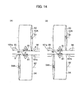
- the reversible cold rolling equipment according to a twenty-fourth invention for solving the above-mentioned second problem is the reversible cold rolling equipment according to the twenty-third invention, characterized in that the mash seam welding machine as the joining device includes a swaging roller having a mechanism for inclining a swaging roller axis relative to a horizontal plane perpendicular to a joining line.
- the buildup coil is formed in the first pass, and reversible rolling of the buildup coil is conducted in the second and following passes, whereby the joint portion can also be rolled at a normal rolling speed, and production efficiency is enhanced, as compared with the related art described in Patent Document 1.
- an unrolled portion is generated only at an innermost circumferential portion and an outermost circumferential portion of the buildup coil, so that off-gage rate can be remarkably lowered.
- the stop of rolling that is, rolling speed becomes 0 mpm
- the coefficient of friction between the work roll and the strip is changed, with the result of formation of stop marks, at the surfaces of the strip clamped between the work rolls.
- the stop marks would be transferred to the work rolls.
- the stop marks may be transferred to the strip surfaces at regular intervals corresponding to the rotational pitch of the work rolls.
- the stop marks are generated in the first pass, they may be made so inconspicuous that they are visually imperceptible, by continuation of the rolling a plurality of times. Where a high quality in regard of surface gloss is required rigorously, however, a problem that the strips with the stop marks are dealt with as defective products is newly generated.
- the strip storage device is provided between the cold rolling mill and the joining device, a strip is stored in the strip storage device at other times than the time of joining, whereas at the time of joining the strip stored in the strip storage device is used to continue rolling even in the condition where the tail end of a preceding coil is stopped. This ensures that stop marks can be prevented from being transferred from the work rolls to the strip during the joining operation.
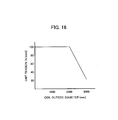
- the rolling speed during joining between the tail end of a preceding coil and the leading end of a succeeding coil is set to be more than 0 mpm and not more than 50 mpm, whereby it is ensured that when the time required for the joining operation is 2 minutes, for example, the length of the strip to be stored can be 100 m or less.
- the length of the strip to be stored in the strip storage device can be shortened, and the strip storage device can be made compact. As a result, equipment configuration can be simplified.
- the rolling speed is set to be more than 0 mpm and not more than 20 mpm, more preferably more than 0 mpm and not more than 10 mpm, and further preferably more than 0 mpm and not more than 5 mpm, whereby the length of the strip to be stored can be set to be not more than 40 m, not more than 20 m, and not more than 10 m, respectively.
- the length of the strip to be stored in the strip storage device can be shortened, and the strip storage device can be made compact. Consequently, equipment configuration can be made smaller.
- the rolling speed in cutting the coil in the final pass is more than 0 mpm and not more than 50 mpm, and a collapsible type reel (described later) is applied.
- a collapsible type reel (described later) is applied.
- the rolling speed is set to be more than 0 mpm and not more than 20 mpm, more preferably more than 0 mpm and not more than 10 mpm, and further preferably more than 0 mpm and not more than 5 mpm.
- the distance between the cutting device and the winding/unwinding device can be shortened, and the equipment length can be shortened. As a result, initial investment expenditure can be curtailed.
- stop marks can be prevented from being transferred from the work rolls to the strip during the joining operation.
- the strip thickness beneath the work roll of the cold rolling mill is computed based on the measured values, and a strip thickness control is conducted by a hydraulic rolling reduction device possessed by the cold rolling mill so that a desired strip thickness will be obtained. Therefore, the accuracy of strip thickness can be maintained.
- a problem of lowering in shape control accuracy is newly generated.
- a shape detector for measuring the shape of the strip is also disposed at a distance from the work rolls of the rolling mill.
- time is taken after the recognition of strip shape by the shape detector until the correction of strip shape by an actuator, whereby shape control accuracy is lowered.
- a lowering in rolling speed generally raises the coefficient of friction between the strip and the work roll, resulting in a rise in rolling load, whereby the strip shape is disturbed.
- strip shape is controlled by a roll bender control or a coolant control or a combination of both controls on the basis of the computation result of roll warpage due to fluctuations in the rolling load at the rolling mill. This makes it possible to compensate for the detection lag and to maintain the shape of the strip.
- the order of feeding of coils into the unwinding device is preliminarily controlled so that the absolute value of a strip thickness difference between a preceding coil and a succeeding coil will be not more than 1 mm, more preferably not more than 0.5 mm. This makes it possible to restrain cracks from being transferred to the adjacent coil layers, due to the step present at the joint portion located at an inner layer portion of the buildup coil.
- joining is conducted by use of a joining device of a mash seam welding system that is inexpensive. This makes it possible to solve the problem relating to cost-effectiveness, in a small- to medium-scale plant with an annual output of about 300,000 to 600,000 tons.
- a mash seam welding machine adopts a system wherein the materials to be joined are lapped on each other and clamped between electrode wheels, and an electric current is passed through the materials to cause contact resistance and internal resistance heating of the materials, whereby the materials are joined together.
- the joint portion upon completion of the joining shows an increased strip thickness of about 1.2 to 1.5 times the original thickness.
- the increase in thickness causes the joint portion to constitute a step, so that an excessive force is exerted on the rolls when the step passes the rolling mill.
- the step may be transferred to the work rolls as marks.
- a cross swaging treatment for rolling the joint portion showing an increased strip thickness is conducted by inclining swaging rollers after the mash seam welding, whereby the step can be smoothened.
- the coil outside diameter of the buildup coil after joining is set to be not more than ⁇ 3000 mm. This ensures that a coil tightening force exerted on the coil can be restricted, and the winding/unwinding device can be restrained from being enlarged due to an enlargement in the coil outside diameter.
- a collapsible type reel having an expansion/collapse function can be applied, instead of a solid block type reel not having an expansion/collapse function. Consequently, the number of winding/unwinding devices can be reduced, as above-mentioned.
- a tension control is performed by which the tension on a strip when the coil outside diameter is larger is gradually decreased as compared with the tension on the strip when the coil outside diameter is smaller.
- a collapsible type reel can be applied, and the number of winding/unwinding devices can be reduced, as will be described later.
- rolling is conducted by use of a two-stand type cold rolling mill.
- the number of rolling passes required until a desired strip thickness is obtained can be reduced, and production efficiency is enhanced.
- the product coils may be required to have a further accuracy.
- the coil cutting in the final pass is performed immediately after passage of the joint portion through the cutting device.
- the joint portion can be disposed at the outer surface of the cut coil, and a treatment of the joint portion after coil extraction can be easily carried out.
- coil cutting in the final pass is conducted immediately before passage of the joint portion through the cutting device and immediately after the passage of the joint portion through the cutting device. This ensures that the joint portion is not wound around the product coil, so that the need for an aftertreatment of the joint portion can be eliminated.
- the work rolls are replaced by dulled work rolls in a condition where a strip is passed through the cold rolling mill, before the start of the final-pass rolling, and then the final-pass rolling is conducted.
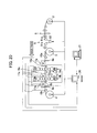
- Fig. 1 is a schematic view of cold-rolled material equipment according to the first embodiment of the present invention.
- the cold-rolled material equipment includes, as main components: a reversible cold rolling mill 1; a unwinding device 2 for unwinding a strip of an input coil 101; a winding/unwinding device 3 (first winding/unwinding device) disposed on the entry side of a first pass of the cold rolling mill 1; a winding/unwinding device 4 (second winding/unwinding device) disposed on the delivery side of the first pass of the cold rolling mill 1; a joining device 5 disposed between the unwinding device 2 and the winding/unwinding device 4 so as to form a buildup coil 102 from a plurality of input coils 101; cutting devices 6 for cutting up the strip of the buildup coil 102 in a final pass to form output coils 103; and a controller 20 for controlling the cold rolling mill 1, the unwinding device 2, the winding/unwinding devices 3, 4, the joining device 5 and the cutting devices 6.
- the reversible cold rolling mill 1 is, for example, a six-high UC mill which includes top and bottom work rolls 11, 11 which make direct contact with a work (material to be rolled) and roll the work, top and bottom intermediate rolls 12, 12 which support the work rolls in the vertical direction, and top and bottom back-up rolls 13, 13 which support the intermediate rolls 12, 12 in the vertical direction.
- a hydraulic rolling reduction device 14 is provided beneath the bottom back-up roll 13. Based on a command, the hydraulic rolling reduction device 14 moves a bearing for the bottom back-up roll 13 up or down, whereby a strip is reduced to obtain a predetermined rolling reduction.
- a load meter 15 is provided on the upper side of the top back-up roll 13, and the rolling reduction of the rolls is controlled correspondingly to a variation in load that is detected by the load meter 15. This series of operations is referred to as reduction control.
- a strip thickness meter 16a, a plate velocity meter 17a and a shape meter 18a are provided on the entry side of the first pass of the cold rolling mill 1
- a strip thickness meter 16b, a plate velocity meter 17b and a shape meter 18b are provided on the delivery side of the first pass of the cold rolling mill 1.
- the unwinding device 2 includes a collapsible type reel having an expansion/collapse function, sets the input coil 101, and unwinds a strip of the input coil 101.
- the winding/unwinding device 3 and the winding/unwinding device 4 each include a collapsible type reel having an expansion/collapse function. Winding and unwinding of a work are repeatedly conducted between the winding/unwinding device 3 and the winding/unwinding device 4, whereby a plurality of passes of cold rolling are carried out while changing the rolling direction.
- the joining device 5 joins the tail end of the strip of a first input coil 101a already unwound with the leading end of the strip of a second input coil 101b subsequently unwound, and subsequently and similarly joins the tail end of the strip of the second input coil 101b with the leading end of the strip of a third input coil 101c, to form a buildup coil 102.
- the cutting device 6a is disposed between the cold rolling mill 1 and the winding/unwinding device 3, and cuts up the strip of the buildup coil 102 in a pass in which the winding in the final pass is completed at the winding/unwinding device 3.
- the cutting device 6b is disposed between the cold rolling mill 1 and the winding/unwinding device 4, and cuts up the strip of the buildup coil 102 in a pass in which the winding is completed at the winding/unwinding device 4.
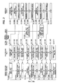
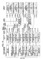
- Figs. 2 to 4 are control flows showing the procedures executed by the controller 20. Dotted lines indicate relationships among the devices 1 to 6. A control in the case where a buildup coil 102 is formed from three input coils 101 and where four passes of rolling are conducted will be described.
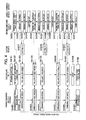
- Figs. 5 to 7 are timetables for each of the devices 1 to 6 corresponding to the control flows, and the same step numbers as in Figs. 2 to 4 are given to those parts of the timetables which correspond to the procedure steps (relevant to the step numbers) in the control flows.
- the controller 20 controls the cold rolling mill 1 in the following manner.
- a first input coil 101a is fed in and mounted onto the unwinding device 2 and a strip thereof is unwound
- the strip of the first input coil 101a is threaded the cold rolling mill 1 (S1101) and is fed further to the winding/unwinding device 4.
- the cold rolling mill 1 is subjected to a reduction control (S1102).
- a reduction control S1102
- acceleration to a steady rolling speed is conducted, and rolling is carried out at a steady rolling speed (S1103).
- the steady rolling speed means a maximum speed at which the capability of the cold rolling mill can be exhibited to the utmost, in obtaining a desired strip thickness.
- the steady rolling speed in reversible cold rolling equipment is generally in the range of 400 to 1400 mpm.
- the cold rolling mill 1 is decelerated and the rolling is stopped (S1104).
- acceleration to the steady rolling speed is again conducted, the cold rolling mill 1 rolls an unrolled strip of the first input coil 101a at the steady rolling speed (S1105), and, in succession, rolls the joined second input coil 101b at the steady rolling speed (S1106).
- the cold rolling mill 1 is decelerated and rolling is stopped (S1107).
- acceleration to the steady rolling speed is again conducted, the cold rolling mill 1 rolls an unrolled portion of the second input coil 101b at the steady rolling speed (S1108), and, in succession, rolls the third input coil 101c at the steady rolling speed (S1109).
- the cold rolling mill 1 When the tail end of the strip of the third input coil 101c is unwound from the unwinding device 2 and fed out, the cold rolling mill 1 is decelerated, and, when the tail end of the strip of the third input coil 101c reaches a position immediately upstream of the cold rolling mill 1, the cold rolling mill 1 stops rolling (S1110), and the first pass of rolling is finished (S1111).
- the controller 20 controls the unwinding device 2 as follows.
- the unwinding device 2 unwinds the strip of the first input coil 101a at a threading speed (S1202).
- the threading speed means a speed of not more than 30 mpm, in general.
- the unwinding device 2 When the unwinding device 2 unwinds the tail end of the strip of the first input coil 101a and the second input coil 101b is fed into and mounted onto the unwinding device 2 (S1204), the unwinding device 2 unwinds the strip of the second input coil 101b at the threading speed to the joining device 5 (S1205). Then, when the leading end of the strip of the second input coil 101b is fed out to a joining position of the joining device 5, the unwinding device 2 stops unwinding (S1206). When the first input coil 101a and the second input coil 101b are joined, the unwinding device 2 unwinds the remaining strip of the second input coil 101b according to the rolling speed of the cold rolling mill 1 which is rolling at the steady rolling speed (S1207).
- the unwinding device 2 When the unwinding device 2 unwinds the tail end of the strip of the second input coil 101b and a third input coil 101c is fed into and mounted onto the unwinding device 2 (S1208), the unwinding device 2 unwinds the strip of the third input coil 101c at the threading speed to the joining device 5 (S1209). Then, when the leading end of the strip of the third input coil 101c is fed out to the joining position of the joining device 5, the unwinding device 2 stops unwinding (S1210). When the second input coil 101b and the third input coil 101c are joined, the unwinding device 2 in succession unwinds the remaining strip of the third input coil 101c according to the rolling speed of the cold rolling mill 1 which is rolling at the steady rolling speed (S1211). When the tail end of the strip of the third input coil 101c is unwound from the unwinding device 2, the unwinding device 2 stops operating (S1212).
- the controller 20 controls the winding/unwinding device 4 (second winding/unwinding device) in the following manner.
- the winding/unwinding device 4 grips the leading end of the strip of the first input coil 101a (S1401).
- the winding/unwinding device 4 winds the strip of the first input coil 101a (S1402), and, according to the procedure of stopping the rolling of the strip of the first input coil 101a, the winding/unwinding device 4 is decelerated and stops winding (S1403).
- the winding/unwinding device 4 winds the remaining strip of the first input coil 101a according to the rolling speed of the cold rolling mill 1 which is rolling at the steady rolling speed (S1404), and, in succession, winds the strip of the second input coil 101b having been joined (S1405). According to the procedure of stopping the rolling of the strip of the second input coil 101b at the time of feeding in the third input coil 101c, the winding/unwinding device 4 is decelerated and stops winding (S1406).
- the winding/unwinding device 4 winds the remaining strip of the second input coil 101b according to the rolling speed of the cold rolling mill 1 which is rolling at the steady rolling speed (S1407), and, in succession, the winding/unwinding device 4 winds the strip of the third input coil having been joined (S1408).
- the winding/unwinding device 4 stops winding (S1409).
- the buildup coil 102 is formed from the three coils 101a, 101b and 101c (S1410). Incidentally, the outside diameter of the buildup coil 102 is not more than ⁇ 3000 mm.
- the controller 20 controls the joining device 5 as follows.
- the joining device 5 joins the first input coil 101a and the second input coil 101b (S1501).
- the joining device 5 joins the second input coil 101b and the third input coil 101c (S1502).
- the winding/unwinding device 3 (first winding/unwinding device) and the cutting devices 6a, 6b are not particularly controlled in the first pass.
- the controller 20 controls the cold rolling mill 1 as follows.
- the cold rolling mill 1 is subjected to a reduction control (S2101).
- the cold rolling mill 1 is accelerated to the steady rolling speed in the reverse direction to that in the first pass, and performs second-pass rolling at the steady rolling speed (S2102).
- the cold rolling mill 1 When the strip of the buildup coil 102 is unwound from the winding/unwinding device 4 with its end gripped by the winding/unwinding device 4, the cold rolling mill 1 is decelerated and stopped (S2103), whereby the second-pass rolling is finished (S2104). Thereafter, before the start of third-pass rolling, the cold rolling mill 1 is subjected to a reduction control such as to obtain a desired strip thickness (S3101). When the preparation for rolling is completed, the cold rolling mill 1 is accelerated to the steady rolling speed in the reverse direction to that in the second pass, and performs the third-pass rolling at the steady rolling speed (S3102).
- the controller 20 controls the winding/unwinding device 3 (first winding/unwinding device) in the following way.
- the winding/unwinding device 3 grips the strip end (S2301).
- the winding/unwinding device 3 winds the strip of the buildup coil 102 (S2302), and, according to the finishing of the second-pass rolling, the winding/unwinding device 3 is decelerated and stopped (S2303).
- the winding/unwinding device 3 unwinds the strip of the buildup coil 102 (S3301), and, according to the finishing of the third-pass rolling, the winding/unwinding device 3 is decelerated and stopped (S3302).
- the controller 20 controls the winding/unwinding device 4 (second winding/unwinding device) as follows.
- the winding/unwinding device 4 unwinds the strip of the buildup coil 102 at the threading speed in the reverse direction as that in the first pass to the winding/unwinding device 3 (S2401).
- the winding/unwinding device 4 unwinds the strip of the buildup coil 102 according to the rolling speed of the cold rolling mill 1 which is rolling at the steady rolling speed (S2402), and is decelerated and stopped according to the finishing of the second-pass rolling (S2403).
- the winding/unwinding device 4 winds the strip of the buildup coil 102 (S3401), and, according to the finishing of the third-pass rolling, the winding/unwinding device 4 is decelerated and stopped (S3402).
- the unwinding device 2, the joining device 5 and the cutting devices 6a, 6b are not particularly controlled in the second and third passes.
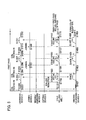
- a main control in the fourth pass (final pass) will be described referring to Fig. 4 .
- the buildup coil is cut up into three output coils 103a to 103c.
- the controller 20 controls the cold rolling mill 1 in the following manner. After the third-pass rolling is finished and before fourth-pass rolling is started, the cold rolling mill 1 is subjected to a reduction control such as to obtain a desired strip thickness (S4101). When the preparation for rolling is completed, the cold rolling mill 1 is accelerated to a steady rolling speed in the reverse direction to that in the third pass, and the fourth-pass (final-pass) rolling is conducted at the steady rolling speed (S4102). According to the procedure in which the strip of the buildup coil 102 is cut by the cutting device 6a and the first output coil 103a is fed out from the winding/unwinding device 3, the cold rolling mill 1 is decelerated, and performs rolling at a low speed (for example, 10 mpm) (S4103).
- a low speed for example, 10 mpm
- the cold rolling mill 1 When the preparation for winding of the remaining strip (corresponding to the second input coil 103b) is completed, the cold rolling mill 1 is again accelerated to the steady rolling speed, and performs rolling of an unrolled strip for final pass of the buildup coil 102 (S4104). Then, according to the procedure in which the strip of the buildup coil 102 is cut by the cutting device 6a and the second output coil 103b is fed out from the winding/unwinding device 3, the cold rolling mill 1 is decelerated and performs rolling at a low speed (for example, 10 mpm) (S4105).
- a low speed for example, 10 mpm
- the cold rolling mill 1 When the preparation for winding of the remaining strip (corresponding to the third input coil 103c) is completed, the cold rolling mill 1 is again accelerated to the steady rolling speed, and performs rolling of an unrolled strip for final pass of the buildup coil 102 at the steady rolling speed (S4106). According to the procedure in which the strip of the buildup coil 102 is cut by the cutting device 6a and the third output coil 103c is fed out by the winding/unwinding device 3, the cold rolling mill 1 is decelerated, and performs rolling at a low speed (for example, 10 mpm) (S4107). When the third output coil 103c is cut off from the strip of the buildup coil 102 by the cutting device 6a, the cold rolling mill 1 stops rolling (S4108), whereby the fourth-pass (final-pass) rolling is finished (S4109).
- a low speed for example, 10 mpm
- the controller 20 controls the winding/unwinding device 3 (first winding/unwinding device) as follows. According to the rolling speed in the fourth pass (final pass) of the cold rolling mill 1 which is rolling at a steady rolling speed, the winding/unwinding device 3 winds the strip of the buildup coil 102 (S4301). When the strip is wound by a predetermined length, the winding/unwinding device 3 winds the strip of the buildup coil 102 according to the rolling speed of the cold rolling mill 1 which is rolling at a low speed (for example, 10 mpm) in conformity with the procedure of cutting (S4302).
- a low speed for example, 10 mpm
- the winding/unwinding device 3 After the first output coil 103a is cut off, the winding/unwinding device 3 winds the remaining strip at a high speed (S4303), and, after the winding is completed, the winding/unwinding device 3 extracts the first output coil 103a and carries it out (S4304). The leading end of the strip fed out subsequently (the leading end of the second input coil 103b) is wound by a belt wrapper (S4305).
- the winding/unwinding device 3 winds the strip of the buildup coil 102 according to the rolling speed in the fourth pass (final pass) of the cold rolling mill 1 which is rolling at the steady rolling speed (S4306).
- the winding/unwinding device 3 When the strip is wound by a predetermined length, the winding/unwinding device 3 winds the strip of the buildup coil 102 according to the rolling speed of the cold rolling mill 1 which is rolling at a low speed (for example, 10 mpm) in conformity with the procedure of cutting (S4307). After the second output coil 103b is cut off, the winding/unwinding device 3 winds the remaining strip at a high speed (S4308). After the winding is completed, the winding/unwinding device 3 extracts the second output coil 103b and carries it out (S4309). The leading end of the strip fed out subsequently (the leading end of the third input coil 103c) is wound by the belt wrapper (S4310).
- the winding/unwinding device 3 winds the strip of the buildup coil 102 according to the rolling speed in the fourth pass (final pass) of the cold rolling mill 1 which is rolling at the steady rolling speed (S4311).
- the winding/unwinding device 3 winds the strip of the buildup coil 102 according to the rolling speed of the cold rolling mill 1 which is rolling at a low speed (for example, 10 mpm) in conformity with the procedure of cutting (S4312).
- the winding/unwinding device 3 winds the remaining strip at a high speed (S4313).
- the winding/unwinding device 3 extracts the third output coil 103c and carries it out (S4314).
- the controller 20 controls the winding/unwinding device 4 (second winding/unwinding device) in the following way.
- the winding/unwinding device 4 According to the rolling speed in the fourth pass (final pass) of the cold rolling mill 1 which is rolling at a steady rolling speed, the winding/unwinding device 4 unwinds the strip of the buildup coil 102 (S4401).
- the winding/unwinding device 4 unwinds the strip of the buildup coil 102 according to the rolling speed of the cold rolling mill 1 which is rolling at a low speed (for example, 10 mpm) in conformity with the procedure of cutting (S4402).
- the winding/unwinding device 4 unwinds the strip of the buildup coil 102 (S4403).
- the winding/unwinding device 4 unwinds the strip of the buildup coil 102 according to the rolling speed of the cold rolling mill 1 which is rolling at a low speed (for example, 10 mpm) in conformity with the procedure of cutting (S4404).
- the winding/unwinding device 4 unwinds the strip of the buildup coil 102 according to the rolling speed of the cold rolling mill 1 which is again rolling at the steady rolling speed (S4405).
- the winding/unwinding device 4 When the strip is unwound by a predetermined length, the winding/unwinding device 4 unwinds the strip of the buildup coil 102 according to the rolling speed of the cold rolling mill 1 which is rolling at a low speed (for example, 10 mpm) in conformity with the procedure of cutting (S4406). After the third output coil 103c is cut off, the winding/unwinding device 4 winds the remaining strip, then extracts an off-gage coil 103d and carries it out (S4407).
- a low speed for example, 10 mpm
- the controller 20 controls the cutting device 6a in the following manner.
- the controller 20 computes each of cutting positions from coil outside diameters and reel rotational speeds at the winding/unwinding devices 3 and 4.
- the cutting device 6a cuts the first output coil 103a off the strip of the buildup coil 102 at a cutting position (S4601), then cuts the second output coil 103b off the remaining strip at the next cutting position (S4602), and further cuts the third output coil 103c off the remaining strip at a cutting position (S4603).
- controller 20 computes the cutting positions on the basis of the coil outside diameters and reel rotational speeds in the present embodiment
- a method may also be adopted in which boring or the like is applied to the cutting positions and the cutting positions are detected by a cutting position detector (not shown) or the like.
- another method may be adopted in which the distance measuring function of the plate velocity meter is used and the cutting positions are grasped through computation of distances.
- the unwinding device 2, the joining device 5 and the cutting device 6b are not particularly controlled in the fourth pass (final pass).
- the strip of the first input coil 101a is unwound at a threading speed, is threaded through the cold rolling mill 1, is gripped by the winding/unwinding device 4, and is wound further by a several-turn amount. Thereafter, the cold rolling mill 1 is subjected to a reduction control (S1201 ⁇ S1202 ⁇ S1101 ⁇ S1401 ⁇ S1102).
- the strip of the first input coil 101a is rolled at a steady rolling speed by the cold rolling mill 1, and is wound by the winding/unwinding device 4 while being unwound from the unwinding device 2 according to the rolling speed of the cold rolling mill 1 (S1203 ⁇ S1103 ⁇ S1402).
- the controller 20 commands a rolling speed of the cold rolling mill 1
- the cold rolling mill 1 is subjected to a feedback control such as to attain a command rolling speed.
- the unwinding device 2 is subjected to a strip feedback control such that the tension on the strip between the unwinding device 2 and the cold rolling mill 1 will be a predetermined value.
- the winding/unwinding device 4 is also subjected to a tension feedback control such that the tension on the strip between the winding/unwinding device 4 and the cold rolling mill 1 will be a predetermined value.
- the strip of the second input coil 101b is unwound from the unwinding device 2 at a threading speed.
- the strip is stopped, and the tail end of the strip of the first input coil 101a and the leading end of the strip of the second input coil 101b are joined by the joining device 5 (S1205 ⁇ S1206 ⁇ S1501).
- the strip of the third input coil 101c is unwound from the unwinding device 2 at a threading speed.
- the strip is stopped, and the tail end of the strip of the second input coil 101b and the leading end of the strip of the third input coil 101c are joined by the joining device 5 (S1209 ⁇ S1210 ⁇ S1502).
- the unwinding device 2 When the strip of the third input coil 101c is unwound, the unwinding device 2 is stopped. When the tail end of the strip of the third input coil 101c reaches a position immediately upstream of the cold rolling mill 1, the cold rolling mill 1 is stopped to finish the first pass, and the winding/unwinding device 4 is stopped according to the stopping of the cold rolling mill 1 (S1212 ⁇ S1110 ⁇ S1111 ⁇ S1409).
- the buildup coil 102 is formed at the winding/unwinding device 4 (S1410).
- the rolling direction is changed over to the reverse direction, and the second pass is started.
- the strip of the buildup coil 102 is unwound from the winding/unwinding device 4 at a threading speed, the tail end of the strip is gripped by the winding/unwinding device 3, and the strip is further wound by a several-turn amount. Thereafter, the cold rolling mill 1 is subjected to a reduction control (S2401 ⁇ S2301 ⁇ S2101).
- the strip of the buildup coil 102 is rolled at a steady rolling speed by the cold rolling mill 1, and is wound by the winding/unwinding device 3 while being unwound from the winding/unwinding device 4 according to the rolling speed of the cold rolling mill 1 (S2402 ⁇ S2102 ⁇ S2302).
- the cold rolling mill 1 is stopped to finish the second pass, and the winding/unwinding device 3 and the winding/unwinding device 4 are stopped according to the stopping of the cold rolling mill 1 (S2103 ⁇ S2403 ⁇ S2303 ⁇ S2104).
- the cold rolling mill 1 In the condition where the strip of the buildup coil 102 is gripped by the winding/unwinding device 4 and the winding/unwinding device 3, the cold rolling mill 1 is subjected to a reduction control, the strip of the buildup coil 102 is rolled by the cold rolling mill 1 at a steady rolling speed, and the strip is wound by the winding/unwinding device 4 while being unwound from the winding/unwinding device 3 according to the rolling speed of the cold rolling mill 1 (S3101 ⁇ S3102 ⁇ S3301 ⁇ S3401).
- the cold rolling mill 1 is stopped to finish the third pass, and the winding/unwinding device 3 and the winding/unwinding device 4 are stopped according to the stopping of the cold rolling mill 1 (S3103 ⁇ S3302 ⁇ S3402 ⁇ S3104).
- the cold rolling mill 1 In the condition where the strip of the buildup coil 102 is gripped by the winding/unwinding device 4 and the winding/unwinding device 3, the cold rolling mill 1 is subjected to a reduction control, and the strip of the buildup coil 102 is rolled by the cold rolling mill 1 at a steady rolling speed.
- the strip of the buildup coil 102 is wound by the winding/unwinding device 3 while being unwound from the winding/unwinding device 4 according to the rolling speed of the cold rolling mill 1 (S4101 - S4102 ⁇ S4301 ⁇ S4401).
- the cold rolling mill 1 is decelerated to a predetermined low speed, and the strip of the buildup coil 102 is rolled at the low speed (for example, 10 mpm) by the cold rolling mill 1.
- the strip of the buildup coil 102 is wound onto the winding/unwinding device 3 while being unwound from the winding/unwinding device 4 according to the rolling speed of the cold rolling mill 1 (S4103 ⁇ S4302 ⁇ S4402).
- the strip of the buildup coil 102 is cut at the strip cutting position by the cutting device 6a, and the remaining strip of the first output coil 103a thus cut is wound onto the winding/unwinding device 3 at a high speed.
- the winding/unwinding device 3 is stopped, and the first output coil 103a is extracted from the winding/unwinding device 3 and carried out (S4601 ⁇ S4303 ⁇ S4304).
- a collapsible type reel is applied to the winding/unwinding device 3, as above-mentioned.
- the remaining strip of the buildup coil 102 having undergone cutting is rolled at a low speed by the cold rolling mill 1, and is unwound from the winding/unwinding device 4 according to the rolling speed of the cold rolling mill 1.
- the leading end of the strip (corresponding to the second output coil 103b) thus fed out is wound by a belt wrapper of the winding/unwinding device 3 (S4305).
- the remaining strip of the buildup coil 102 is rolled by the cold rolling mill 1 at a steady rolling speed, and is wound onto the winding/unwinding device 3 while being unwound from the winding/unwinding device 4 according to the rolling speed of the cold rolling mill 1 (S4104 ⁇ S4306 ⁇ S4403).
- the cold rolling mill 1 is decelerated to a predetermined low speed.
- the strip of the buildup coil 102 is rolled by the cold rolling mill 1 at the low speed, and is wound onto the winding/unwinding device 3 while being unwound from the winding/unwinding device 4 according to the rolling speed of the cold rolling mill 1 (S4105 ⁇ S4307 ⁇ S4404).
- the strip of the buildup coil 102 is cut at a strip cutting position by the cutting device 6a, and the remaining strip of the second output coil 103b thus cut off is wound onto the winding/unwinding device 3 at a high speed.
- the winding/unwinding device 3 is stopped, and the second output coil 103b is extracted from the winding/unwinding device 3 and is carried out (S4602 ⁇ S4308 ⁇ S4309).
- the remaining strip of the buildup coil 102 having undergone cutting is rolled at a low speed by the cold rolling mill 1, and is unwound from the winding/unwinding device 4 according to the rolling speed of the cold rolling mill 1.
- the leading end of the strip (corresponding to the third output coil 103c) thus fed out is wound by a belt wrapper of the winding/unwinding device 3 (S4310).
- the remaining strip of the buildup coil 102 is rolled at a steady rolling speed by the cold rolling mill 1, and is wound onto the winding/unwinding device 3 while being unwound from the winding/unwinding device 4 according to the rolling speed of the cold rolling mill 1 (S4106 ⁇ S4311 ⁇ S4405).
- the cold rolling mill 1 is decelerated to a predetermined low speed, and the strip of the buildup coil 102 is rolled by the cold rolling mill 1 at the low speed.
- the strip of the buildup coil 102 is wound onto the winding/unwinding device 3 while being unwound from the winding/unwinding device 4 according to the rolling speed of the cold rolling mill 1 (S4107 ⁇ S4312 ⁇ S4406).
- the strip of the buildup coil 102 is cut at a strip cutting position by the cutting device 6a, and the remaining strip of the third output coil 103c thus cut off is wound onto the winding/unwinding device 3 at a high speed.
- the winding/unwinding device 3 is stopped, and the third output coil 103c is extracted from the winding/unwinding device 3 and is carried out (S4603 ⁇ S4313 ⁇ S4314).
- the cold rolling mill 1 stops rolling, to finish the fourth pass, and the remaining strip of the buildup coil 102 thus cut is wound onto the winding/unwinding device 4.
- the off-gage coil 103d thus wound is extracted from the winding/unwinding device 4 and is carried out (S4108 ⁇ S4109 ⁇ S4407).
- a collapsible type reel is applied to the winding/unwinding device 4, as above-mentioned.
- the output coils 103a to 103c are carried out from the winding/unwinding device 3, whereas the off-gage coil 103d is carried out from the winding/unwinding device 4.
- the strip of the buildup coil 102 is cut by the cutting device 6b, the output coils 103a to 103c are extracted from the winding/unwinding device 4 and is carried out, whereas the off-gage coil 103d is carried out from the winding/unwinding device 3.
- Fig. 8 is a schematic view of cold-rolled material equipment according to the first related art.
- the same components as those in Fig. 1 are denoted by the same reference symbols as used above.
- the cold-rolled material equipment (RCM equipment) includes, as main components: a reversible cold rolling mill 1; a unwinding device 2 for unwinding a strip to the cold rolling mill 1 in a first pass; a winding/unwinding device 3 disposed on the entry side of the first pass of the cold rolling mill 1; the winding/unwinding device 4 disposed on the delivery side of the first pass of the cold rolling mill 1; and a controller 20 for controlling the cold rolling mill 1, the unwinding device 2, and the winding/unwinding devices 3, 4.
- An input coil 101a is fed into the unwinding device 2, the leading end of the strip of the input coil 101a that is threaded the cold rolling mill 1, is gripped by the winding/unwinding device 4, and is wound further by a several-turn amount.
- a first pass of rolling is started by the cold rolling mill 1.
- the tail end of the strip reaches a position immediately upstream of the cold rolling mill 1, the first-pass rolling is finished.
- the leading end of the strip is threaded the cold rolling mill 1 in the reverse direction as that in the first pass, the leading end is gripped by the winding/unwinding device 3, and the strip is wound further by a several-turn amount.
- a second pass of rolling is started by the cold rolling mill 1. In the condition where the strip end portion is wound onto the winding/unwinding device 4 by a several-turn amount, the second-pass rolling is finished.
- the third pass of rolling is started by the cold rolling mill 1.
- the third-pass rolling is finished.
- the fourth pass of rolling is started by the cold rolling mill 1.
- An output coil 103a having undergone the fourth-pass rolling is wound onto the winding/unwinding device 3, is extracted therefrom and is carried out.
- an input coil 101b is fed into the unwinding device 2
- an output coil 103b is carried out from the winding/unwinding device 3
- an input coil 101c is fed into the unwinding device 2
- an output coil 103c is carried out from the winding/unwinding device 3.
- the leading end and tail end portions of the strips of the output coils 103a to 103c are unrolled portions, and the off-gage rate is as high as about 2.5%.
- threading the cold rolling mill 1 is conducted six times in total, and reversible rolling is performed twelve times in total.
- the actual rolling time in the operation time is short, so that production efficiency is poor.
- the second related art is to solve the problem involved in the first related art.
- Fig. 9 is a schematic view of cold-rolled material equipment according to the second related art.
- the components equivalent to those in Fig. 1 are denoted by the same reference symbols as used above.
- the cold-rolled material equipment includes, as main components: a reversible cold rolling mill 1; a unwinding device 2 for unwinding a strip of an input coil 101; a winding/unwinding device 3A (first winding/unwinding device) disposed on the entry side of a first pass of the cold rolling mill 1; a winding/unwinding device 4A (second winding/unwinding device) disposed on the delivery side of the first pass of the cold rolling mill 1; a joining device 5 for forming a buildup coil 102 from a plurality of input coils 101; a cutting device 6 for cutting the strip of the buildup coil 102 to form output coils 103; a buildup-coil winding/unwinding device 111 for forming the buildup coil; a winding device 112 which is disposed on the entry side of the first pass of the cold rolling mill 1 and winds the output coil 103; a winding device 113 disposed on the delivery side of the
- solid type reels are applied to the winding/unwinding devices 3A, 4A and the buildup-coil winding/unwinding device 111, whereas collapsible type reels are applied to the unwinding device 2 and the winding devices 112, 113.
- the strip of the second input coil 101b is unwound until its leading end is fed out to the joining position of the joining device 5, whereon the strip is stopped, and the tail end of the strip of the first input coil 101a and the leading end of the strip of the second input coil 101b are joined by the joining device 5.
- the strip obtained upon the joining is wound onto the buildup-coil winding/unwinding device 111.
- the tail end of the strip of the second input coil 101b and the leading end of the strip of a third input coil 101c are joined by the joining device 5, and the strip obtained upon the joining is wound onto the buildup-coil winding/unwinding device 111. Consequently, a buildup coil 102 is formed at the buildup-coil winding/unwinding device 111.
- the strip of the buildup coil 102 is unwound from the buildup-coil winding/unwinding device 111, is threaded the cold rolling mill 1, and is gripped by the winding/unwinding device 4A. After a reduction control, a first pass of rolling is conducted by the cold rolling mill 1. Thereafter, the strip is subjected to second and third passes of reversible rolling between the winding/unwinding device 3A and the winding/unwinding device 4A.
- the grip by the winding/unwinding device 3A is released, and the strip end is unwound from the winding/unwinding device 3A.
- the strip end thus unwound is gripped by the winding device 112, and, after a reduction control, a fourth pass of rolling is conducted.
- the strip of a predetermined length corresponding to an output coil 103a is wound onto the winding device 112
- the strip of the buildup coil 102 is cut at a strip cutting position by the cutting device 6a, and the output coil 103a thus cut off is extracted from the winding device 112 and carried out.
- the remaining strip is also cut by the cutting device 6a, and output coils 103b, 103c thus cut off are sequentially extracted from the winding device 112 and carried out.
- a collapsible type reel is applied to the winding device 112, as above-mentioned.
- the cutting device 6b is disposed between the cold rolling mill 1 and the winding device 113, and cuts the strip of the buildup coil 102 in a pass in which winding is completed at the winding device 113.
- unrolled portions are generated only at In this case, unrolled portions are generated only at the leading end of the strip of the output coil 103a and the tail end of the strip of the output coil 103c, so that off-gage rate can be remarkably lowered.
- the threading the cold rolling mill 1 is conducted twice and reverse rolling is conducted four times, the actual rolling time in the operation time is prolonged, and production efficiency is enhanced, as compared with the first related art.
- the cold-rolled material equipment according to the second related art is presumed to be applied to a plant of a comparatively large scale with an annual output of not less than 800,000 tons.
- the cold-rolled material equipment according to the second related art has an increased initial cost due to the added components such as the joining device 5, the cutting device 6, the buildup-coil winding/unwinding device 111 and the winding devices 112, 113, as compared with the cold-rolled material equipment according to the first related art.
- the winding/unwinding devices 3A, 4A and the buildup-coil winding/unwinding device 111 are necessarily large, so that the initial cost is increased.
- the winding devices 112 and 113 to which collapsible type reels are applied are separately needed, in addition to the winding/unwinding devices 3A, 4A and the buildup-coil winding/unwinding device 111.
- the cold-rolled material equipment according to the second related art is presumed to be applied to a plant of a comparatively large scale with an annual production of not less than 800,000 tons. In this case, some rise in initial cost does not matter, since priority is given to a lowering in off-gage rate and an enhancement of production efficiency. If the cold-rolled material equipment according to the second related art is applied to a small- to medium-scale plant with an annual production of about 300,000 to 600,000 tons, however, the problem of the initial cost becomes conspicuous, and there is a problem from the viewpoint of cost-effectiveness.
- the winding devices 112 and 113 indispensable in the second related art are unnecessitated, and the winding/unwinding devices 3 and 4 can be restrained from being enlarged. This ensures that equipment configuration can be simplified, and, consequently, initial cost can be further curtailed.
- a joining device of a mash seam welding system is used as the joining device 5. This makes it possible to enhance investment cost-effectiveness.
- the buildup coil 102 In formation of the buildup coil 102, it is presumed that the first input coil 101a and the second input coil 101b which have a uniform thickness are joined, and the second input coil 101b and the third input coil 101c which have a uniform thickness are joined; in other words, it is presumed that the buildup coil 102 is free of variations in thickness. In practice, however, differences in strip thickness may be present among the input coils 101a to 101c due to errors, causing generation of a step at the joint portion. The joint portion is located in an inner layer portion of the buildup coil 102; if a tension is exerted on the coil in this condition, therefore, the step at the joint portion would be transferred to the inside and the outside of each layer, leading to a product defect which is dealt with as a crack.
- the first input coil 101a has a strip thickness of 3.2 mm and the second input coil 101b has a strip thickness of 2.0 mm and the third input coil 101c has a strip thickness of 2.6 mm
- a step of 1.2 mm will be formed at the joint portion between the first input coil 101a and the second input coil 101b.
- a process computer 21 provided as a host computer for the controller 20 preliminarily manages the strip thickness of each of the input coils 101, and, for example, the order of feeding-in of the second input coil 101b and the third input coil 101c is changed.
- the step at the joint portion between the first input coil 101a and the second input coil 101b is 0.6 mm
- the step at the joint portion between the second input coil 101b and the third input coil 101c is 0.6 mm.
- the order of the coils fed into the unwinding device 2 is conditioned beforehand so that the absolute values of strip thickness differences will be not more than 1 mm, whereby it is possible to lower the possibility that a step at a joint portion located in an inner layer portion of the buildup coil might cause transfer of a crack to the adjacent coil layers. Furthermore, it is desirable that the absolute values of strip thickness differences will be not more than 0.5 mm.
- a joining device of a mash seam welding system is used as the joining device 5, for the purpose of reducing initial cost.
- Fig. 10 is a conceptual view of the mash seam welding system.
- a mash seam welding machine adopts a system wherein materials to be joined are placed to overlap each other and clamped between electrode wheels, and an electric current is passed therethrough to cause contact resistance and internal resistance heating of the materials, whereby a molten-solidified portion called nugget N is formed and the materials are joined.
- the joint portion increased in thickness constitutes a step, which applies an excessive force to the rolls when passing the rolling mill 1.
- the step may be transferred onto the work rolls as marks.
- the step at the joint portion may be transferred to the inside and the outside of each coil layer. There has been a problem of causing such a product defect.
- Fig. 11 is a schematic view of the joining device 5.
- the joining device 5 includes a pair of upper and lower electrode wheels 51, 52, a pair of upper and lower pressure rollers 53, 54, entry-side and delivery-side clamp devices 55, 56, a carriage frame 57, an electrode wheel pressing device 58 and a pressure roller pressing device 59.
- the upper electrode wheel 51 and the upper pressure roller 53 are supported on an upper horizontal frame of the carriage frame 57 through the electrode wheel pressing device 58 and the pressure roller pressing device 59, respectively, whereas the lower electrode wheel 52 and the lower pressure roller 54 are supported on a lower horizontal frame of the carriage frame 57 through mount blocks, respectively.
- the pair of upper and lower pressure rollers 53, 54 are disposed adjacently to the pair of upper and lower electrode wheels 51, 52 in the carriage frame 57.
- both end portions of the strips are placed to overlap each other.
- the strips are gripped by clamp members of the entry-side and delivery-side clamp devices 55, 56, to be fixed in position.
- the carriage frame 57 is moved in a welding direction by a driving device, whereby the pair of upper and lower electrode wheels 51, 52 and the pair of upper and lower pressure rollers 53, 54 supported on the carriage frame 57 are moved relative to the strips, and joining and pressing are carried out in a continuous manner.
- the overlapping portions of the strips are clamped between the pair of upper and lower electrode wheels 51, 52, the electrode wheels 51, 52 are pressed against the overlapping portions of the strips by the electrode wheel pressing device 58, and, while positively driving the electrode wheels 51, 52 to rotate by an electric motor, a welding current is passed to the electrode wheels 51, 52 to cause resistance heating, whereby welding (mash seam welding) is achieved.
- the joint portion (welded joint) J is clamped between the pair of upper and lower pressure rollers 53, 54, the pressure rollers 53, 54 are pressed against the joint portion by the pressure roller pressing device 59, and, while positively driving the pressure rollers 53, 54 to rotate by an electric motor, the joint portion of the strip is pressed and rolled.
- the pressure roller pressing device 59 is provided with an inclining mechanism 60 for controlling the inclination angles of axes 61, 62 of the pressure rollers 53, 54.
- an inclining mechanism 60 for controlling the inclination angles of axes 61, 62 of the pressure rollers 53, 54.
- the electric motor and a chain and a sprocket mechanism for driving the pressure rollers to rotate are omitted in the drawing.
- Fig. 12 is a schematic view of the inclining mechanism 60.
- the inclining mechanism 60 includes a rotating shaft 71 rotatably inserted in the upper horizontal frame of the carriage frame 56, and an electric motor 74 for rotationally driving the rotating shaft 71 through pinions 72, 73, and the electric motor 74 is controlled by an inclination angle controller 75.
- the inclining mechanism 60 has an angle sensor 76 for detecting the inclination angle of the pressure roller 53.
- the inclination angle controller 75 is supplied with angle information according to the strip thickness of the strips from a host controller 77, sets an angle, and controls driving of the electric motor 74 by use of a signal from the of the pressure roller 53 will coincide with the set angle.
- Fig. 13 is a diagram showing a metal flow within an arc-of-contact length in the case of rolling a joint portion J by inclining the axes 61, 62 of the pressure rollers 53, 54, and it shows the case of the upper pressure roller 53, as an example.
- letter A denotes an arrow indicating the moving direction (rolling direction) of the pressure roller 53
- letter X denotes a straight line virtually indicating the weld line (joining line) of the joint portion J present on the moving direction A
- letter Y denotes a straight line orthogonal to the weld line X.
- numeral 63 denotes a straight line passing through a width-directionally central portion in a direction perpendicular to the axis of the pressure roller 53
- letter ⁇ denotes the inclination angle of the pressure roller 53 (the angle between the weld line X and the straight line 63 in the direction perpendicular to the axis of the upper pressure roller 53).
- numeral 64 denotes an arc-of-contact length portion where the pressure roller 53 makes contact with the joint portion J
- letter R denotes a velocity vector of the pressure roller 53 in the denotes a velocity vector of the pressure roller 53 in the arc-of-contact length portion 64
- letter R1 denotes that component of the velocity vector R which is in the direction of the weld line X
- letter R2 denotes that component of the velocity vector R which is in a direction perpendicular to the weld line X.
- the angle ⁇ by which the pair of upper and lower pressure rollers 53, 54 are inclined can be set in two kinds of orientations.
- a first setting method corresponds to a case where, as shown in Figs. 14A and 14B , the axes 61, 62 of the pair of pressure rollers 53, 54 are each inclined relative to the straight line Y orthogonal to the weld line X in such a manner that moving direction portions 53A, 54A of the pair of pressure rollers 53, 54 are oriented in the opposite directions to the directions where the strip portions contacted first by the pressure rollers 53, 54 are present, in a horizontal plane.
- the axes 61, 62 of the pressure rollers 53, 54 are inclined in such a manner that the axial ends of the pressure rollers 53, 54 located at those portions of the joint portion J of the strip which are on the thicker side of the step S at the joint portion J (those material portions of the joint portion J which are contacted first by the pressure rollers 53, 54) are oriented in the rolling direction A of the joint portion J.
- the shearing forces 82 corresponding to the velocity vector component R2 act in the directions from the step S of the joint portion J of the strip toward the strip portions contacted first by the pressure rollers 53, 54, so that the step portion is rolled and smoothened while a shearing deformation is imparted thereto in the same direction perpendicular to the weld line.
- forces in the opposite directions to the shearing forces 82 act on the pressure rollers 53, 54 from the joint portion J as thrust forces 81.
- the shearing forces 82 as reactional forces of the thrust forces 81 act on the joint portion J.
- a second setting method corresponds to a case where, as shown in Figs. 15A and 15B , the pressure rollers 53, 54 are inclined in the reverse directions to those in the first setting method.
- the axes 61, 62 of the pair of pressure rollers 53, 54 are each inclined relative to the straight line Y orthogonal to the weld line X in such a manner that the moving direction portions 53A, 54A of the pair of pressure rollers 53, 54 are oriented in the directions where the strip portions contacted first by the pressure rollers 53, 54 are present, in a horizontal plane.
- the axes 61, 62 of the pressure rollers 53, 54 are inclined in such a manner that the axial ends of the pressure rollers 53, 54 located at those portions of the joint portion J (mash seam-welded joint) of the strip which are on the thinner side of the step S at the joint portion J (those material portions of the joint portion J which are not contacted first by the pressure rollers 53, 54) are oriented in the rolling direction A of the joint portion J.
- the shearing forces 82 corresponding to the velocity vector component R2 act in the directions from the step S of the joint portion J of the strip toward the strip portions relevant to the metallic material contacted first by the pressure rollers 53, 54, so that the step portion is rolled and smoothened while a shearing deformation is imparted thereto in the same direction perpendicular to the weld line.
- forces in the opposite directions to the shearing forces 82 act on the pressure rollers 53, 54 from the joint portion J as thrust forces 81.
- the first setting method is adopted.
- the reason is as follows. Even when the pair of upper and lower pressure rollers 53, 54 are inclined by the second setting method, the step S can be smoothened because it undergoes a plastic flow caused by the shearing force 82. In this case, however, the portion of the step S is folded into the base material as shown in Fig. 15B , so that a problem of embedding of the step S into the base material in a crack-like form is newly generated. This does not matter in the case where the joint portion J is required simply to have a smooth surface and it is applied to a part which does not need strength.
- the directions in which the pressure rollers 53, 54 are to be inclined are preferably as shown in Figs. 14A and 14B , wherein the axes 61, 62 of the pair of pressure rollers 53, 54 are each inclined relative to the straight line Y orthogonal to the weld line X in such a pair of pressure rollers 53, 54 are oriented in the opposite directions to the directions where the strip portions contacted first by the pressure rollers 53, 54 are present, in a horizontal plane.
- the step at the joint portion can be smoothened while avoiding embedding of the step S into the base material in a crack-like form, so that the quality of the joint portion is enhanced.
- the outside diameter of the buildup coil 102 is not more than ⁇ 3000 mm.
- the tension on the strip when the outside diameter of the buildup coil 102 is larger is set to be gradually lowered, as compared with that when the outside diameter is smaller.
- Fig. 16 is a diagram showing a tension control at the time of winding the buildup coil 102.
- the winding/unwinding devices 3, 4 in the present invention permits application of collapsible type reels thereto, while the winding/unwinding devices 3A, 4A in the second related art necessitate application of solid block type reels thereto.
- the cutting devices 6a, 6b each have an swing mechanism (not shown).
- a cutting device in tandem cold rolling equipment with an annual production of not less than 1,000,000 tons is generally of a flying shear type for cutting the coil while rolling is continued, and the strips after cutting-up are alternately wound by use of two winding devices.
- the strip velocity at the time of coil cutting is lowered only to a value of about 100 to 300 mpm.
- the conventional cutting device of the flying shear type for cutting the coil while rolling is continued cannot be said inexpensive. Therefore, when the conventional cutting device is adopted in a small- to medium-scale plant with an annual production of about 300,000 to 600,000 tons, there arises a problem of an increased initial cost.
- the rolling speed at the time of cutting the buildup coil 102 is set at a low speed (for example, 10 mpm), as has been described in connection with the operation in the fourth pass (final pass). Therefore, a comparatively inexpensive cutting device having an swing mechanism can be applied, instead of the conventional expensive cutting device of the flying shear type, so that initial cost can be curtailed.
- the cutting device 6a having an swing mechanism is capable of cutting a strip without stopping rolling, as has been described in connection with the operation in the fourth pass.
- the rolling speed at the time of cutting up the buildup coil 102 by the cutting device 6a is set at a low speed (for example, 10 mpm), as has been described in connection with the operation in the fourth pass (final pass).
- a low speed for example, 10 mpm
- the output coil 103 is cut off by the cutting device 6a, is wound onto the winding/unwinding device 3 at a high speed, and is thereafter extracted and carried out. This series of operations are carried out, for example, in about 30 seconds.
- the first output coil 103a is carried out before the preparation for winding of the second output coil 103b.
- rolling is continued (low-speed rolling) even at the time of cutting, whereby stop marks of the work rolls can be prevented from being formed on the strip.
- the product coil may be required to have further accuracy.
- the coil cutting in the final pass is conducted immediately after the passage of the joint portion through the cutting device.
- the cutting position is located immediately behind the joint portion.
- the cutting position is computed by the controller 20, from the coil outside diameters and the reel rotational speeds of the winding/unwinding devices 3, 4.
- the coil cutting in the final pass may be conducted immediately before the passage of the joint portion through the cutting device and immediately after the passage of the joint portion through the cutting device.
- the joint portion is cut off from the output coil 103 by the cutting device 6a.
- the work rolls may be replaced with dulled work rolls in the condition where the strip is threaded the cold rolling mill, followed by the final-pass rolling.
- Fig. 17 is schematic view of a cold-rolled material equipment according to the second embodiment of the present invention. While the cold rolling mill 1 in the first embodiment has been of a one-stand type, cold rolling mills 1a, 1b in the second embodiment constitute a two-stand type mill.
- the cold rolling mill 1 in the first embodiment has been described to be of the one-stand type for convenience of description, a two-stand type is preferred in order that the effects to enhance the annual production and to reduce the off-gage rate are exhibited to the utmost. Further, the two-stand type is preferable also from the viewpoint of investment cost-effectiveness.
- the second embodiment is the same as the first embodiment in other points of configuration, in control, in operation, and in the effects obtained.
- Fig. 18 is a schematic view of cold-rolled material equipment according to the third embodiment of the present invention.
- the cold-rolled material equipment according to the present embodiment has a strip storage device 9 disposed between the joining device 5 and the cold rolling mill 1, in addition to the configuration of the cold-rolled material equipment according to the first embodiment.
- the strip storage device 9 has a movable roller 92 provided between two stationary rollers 91a, 91b.
- the strip storage device 9 stores a strip by lowering the movable roller 92 by means of a driving device (not shown), and release the stored strip by raising the movable roller 92.
- the operation of the strip storage device 9 is controlled by the controller 20.
- Fig. 19 is a control flow showing a procedure executed by the controller 20. Controls in the second to fourth passes are the same as those in the first embodiment; therefore, only a control in the first pass will be shown.
- the controller 20 controls the cold rolling mill 1 so that the cold rolling mill 1 is stopped according to the procedure concerning the feeding-in of the input coil 101 and the joining (S1104, S1107).
- the controller 20 controls the cold rolling mill 1 so as to perform rolling at a low speed (for example, 10 mpm) according to the procedure related to the feeing-in of the input coil 101 and the joining (S1104B, S1107B).
- the controller 20 controls the winding/unwinding device 4 so that the winding/unwinding device 4 is stopped according to the stopping of the cold rolling mill 1 (S1403, S1406).
- the controller 20 controls the winding/unwinding device 4 so as to winding the strip at the low speed according to the low-speed rolling of the cold rolling mill 1 (S1403B, S1406B).
- the controller 20 controls the strip storage device 9 in the following manner.
- the movable roller 92 is lowered, and the strip storage device 9 thereby starts storing the strip.
- the lowering of the movable roller 92 is stopped (S1901B).
- the movable roller 92 is raised, and the strip storage device 9 thereby gradually releases the stored strip.
- Controls concerning the unwinding device 2 and the joining device 5 are substantially the same as those in the first embodiment.
- the cold rolling mill 1 in the first pass, is kept stopped (S1104) during a series of operations in which the second input coil 101b is fed into the unwinding device 2 and the tail end of the strip of the first input coil 101a and the leading end of the strip of the second input coil 101b are joined (S1204 ⁇ S1205 ⁇ S1206 ⁇ S1501).
- the cold-rolled material equipment according to the present embodiment operates as follows.
- the strip storage device 9 stores the strip (S1201 ⁇ S1202 ⁇ S1901B). Thereafter, the strip of the first input coil 101a is rolled at a steady rolling speed and unwound (S1203 ⁇ S103 ⁇ S1402).
- the second input coil 101b is fed into and mounted onto the unwinding device 2, the strip thereof is unwound, and the tail end of the strip of the first input coil 101a and the leading end of the strip of the second input coil 101b are joined (S1204 ⁇ S1205 ⁇ S1206 ⁇ S1501).
- the strip storage device 9 must store the strip by a length of 20 m.
- the strip of the second input coil 101b When the strip of the second input coil 101b is unwound and the tail end of the strip reaches and is stopped at the joining position of the joining device 5, the strip is released from the strip storage device 9; simultaneously, the unrolled strip of the second input coil 101b is rolled at a low speed by the cold rolling mill 1, to be wound onto the winding/unwinding device 4 according to the rolling speed of the cold rolling mill 1 (S1904B ⁇ S1107B ⁇ S1406B).
- the third input coil 101c is fed into and mounted onto the unwinding device 2, the strip thereof is unwound, and the tail end of the strip of the second input coil 101b and the leading end of the strip of the third input coil 101c are joined (S1208 ⁇ S1209 ⁇ S1210 ⁇ S1502).
- the unwinding device 2 When the strip of the third input coil 101c is unwound, the unwinding device 2 is stopped, and, when the tail end of the strip of the third input coil 101c reaches a position immediately upstream of the cold rolling mill 1, the cold rolling mill 1 is stopped, to finish the first pass.
- the winding/unwinding device 4 is stopped according to the stopping of the cold rolling mill 1 (S1212 ⁇ S1110 ⁇ S1111 ⁇ S1409).
- the buildup coil 102 is formed at the winding/unwinding device 4 (S1410).
- the cold rolling mill 1 in the first pass, is kept stopped (S1104) during a series of operations in which the second input coil 101b is fed into the unwinding device 2 and the tail end of the strip of the first input coil 101a and the leading end of the strip of the second input coil 101b are joined (S1204 ⁇ S1205 - S1206 ⁇ S1501).
- the cold rolling mill 1 is kept stopped (S1108) during a series of operations in which the third input coil 101c is fed in and the tail end of the strip of the second input coil 101b and the leading end of the strip of the third input coil 101c are joined (S1208 ⁇ S1209 ⁇ S1210 - S1502).
- the stop of rolling that is, rolling speed becomes 0 mpm
- the coefficient of friction between the work roll and the strip is changed, with the result of formation of stop marks, at the surfaces of the strip clamped between the work rolls. Further, the stop marks would be transferred to the work rolls. During the subsequent rolling, therefore, the stop marks may be transferred to the strip surfaces at regular intervals corresponding to the rotational pitch of the work rolls.
- the stop marks are generated in the first pass, they may be made so inconspicuous that they are visually imperceptible, by continuation of the rolling a plurality of times. Where a high quality in regard of surface gloss is required high quality in regard of surface gloss is required rigorously, however, a problem that the strips with the stop marks are dealt with as defective products is newly generated.
- the strip storage device 9 is provided, and the strip is stored into the strip storage device 9 at other times than the time of joining. At the time of joining, the strip stored in the strip storage device 9 is released, and rolling is thereby continued by low-speed rolling even in the condition where the tail end of the preceding coil is stopped. This makes it possible to prevent stop marks of the work rolls from being formed on the strip during the joining operation.
- the length of the strip stored can be set to 20 m by setting the rolling speed in low-speed rolling to 10 mpm.
- the rolling speed in the low-speed rolling is lowered, the length of the strip stored in the strip storage device can be shortened, and the strip storage device can be made compact accordingly.
- equipment configuration can be simplified.
- the rolling speed can be lowered to the limiting resolution speed (approaching zero) of the cold rolling mill 1.
- low-speed rolling is conducted during the joining operation and at the time of cutting. This, however, would produce a new problem of a lowering in strip thickness control accuracy or a lowering in shape control accuracy.
- feedback control is applied to the strip thickness control and shape control during rolling at a steady rolling speed, such a control leads to a conspicuous time lag and, hence, to a lowered accuracy when applied to rolling at a low speed.
- the cold rolling mill 1 is, for example, a six-high UC mill including top and bottom work rolls 11, 11 which make direct contact with the work (material to be rolled) and roll the work, top and bottom intermediate rolls 12, 12 which support the work rolls in the vertical direction, and top and bottom back-up rolls 13, 13 which support the intermediate rolls 12, 12 in the vertical direction.
- a hydraulic rolling reduction device 14 is provided beneath the bottom back-up roll 13. Based on a command from the controller 20, the hydraulic rolling reduction device 14 moves a bearing for the bottom back-up roll 13 up or down, whereby the strip is rolled in such a manner as to obtain a predetermined rolling reduction.
- a load meter 15 is provided on the upper side of the top back-up roll 13, and information detected by the load meter 15 is outputted to the controller 20.
- a strip thickness meter 16a, a strip velocity meter 17a, a shape meter 18a are provided on the entry side of the first pass of the cold rolling mill 1.
- a strip thickness meter 16b, a strip velocity meter 17b and a shape meter 18b are provided on the delivery side of the first pass of the cold rolling mill 1. Pieces of information detected respectively by these meters are outputted to the controller 20.
- the strip thickness meters 16 may be laser Doppler type velocimeters; or, alternatively, the strip velocity may be detected from the rotational speed of a deflector roller or the shape detector.
- Strip thickness control during steady rolling will be described.
- BISRA-AGC control and monitor AGC control are jointly used, when required.
- the BISRA-AGC control is a control process in which a variation in the strip thickness on the entry side of the cold rolling mill 1 is detected as a variation in rolling load by the load meter 15, and the rolling reduction of the rolls is controlled correspondingly to the load variation detected.
- the monitor AGC control is a control process in which a variation in the strip thickness on the delivery side of the cold rolling mill 1 is detected by the strip thickness meter 16b on the delivery side, and the rolling reduction is controlled by proportional-plus-integral control while feeding back the thickness variation detected.
- the strip thickness meter 16b is provided at a distance of several meters from the cold rolling mill 1, so that a time lag is generated in the value detected by the strip thickness meter 16b.
- the time lag produces little influence on control.
- this system is applied during low-speed rolling (for example, at 10 mpm), however, the influence of the time lag makes it impossible to obtain appropriate information, and lowers the accuracy of strip thickness control.
- Strip thickness control during low-speed rolling will be described.
- MF-AGC control is applied to low-speed rolling.
- the MF-AGC control is a control as follows.
- the values detected by the strip thickness meter 16a on the entry side are put to tracking up to a position directly under the rolling stand deemed as the object of control.
- the strip velocity meters 17a, 17b on the entry side and the delivery side the respective strip velocities on both sides are detected.
- the controller 20 estimates the delivery-side strip thickness by multiplying the entry-side strip thickness by an entry-side-to-delivery-side strip velocity ratio, and controls the rolling reduction so that the deviation between the estimated value and a target value of strip thickness is reduced to zero.
- Shape control during steady rolling will be described.
- a feedback control is applied in which the shape of the strip is measured by the shape meter 18b on the delivery side, and correction is conducted based on deviations between command values of shape and actual values of shape.
- the shape meter 18b is provided at a distance of several meters to ten and several meters from the cold rolling mill 1, so that a time lag is generated in the values detected at the shape meter 18b.
- the time lag produces little influence during steady rolling (for example, at 1000 mpm).
- this system is applied during low-speed rolling (for example, at 10 mpm), however, the influence of the time lag makes it impossible to obtain appropriate information, and lowers the accuracy of shape control.
- Strip thickness control during low-speed rolling will be described.
- the roll bender control is a control as follows. Fluctuations in the rolling load in the cold rolling mill 1 are detected by the load meter 15. The controller 20 computes a roll deflection attendant on the fluctuations, and, based on the result of computation, exerts a force on an end portion of the work roll 11 or the intermediate roll 12 so as to forcibly bend the roll, thereby controlling the roll deflection.
- the coolant control is a control as follows. Several blocks obtained by cutting the roll surface of the work roll 11 or the intermediate roll 12 are preliminarily set. Fluctuations in the rolling load in the cold rolling mill 1 are detected by the load meter 15. The controller 20 computes a roll deflection attendant on the fluctuations, and, based on the result of computation, varies the quantity of coolant jetted on a block basis, thereby controlling the amount of expansion of the roll due to the working heating attendant on the rolling.
- the configurations concerning the strip thickness control and the shape control are provided also in the first embodiment, and the same or similar control is applied also during the low-speed rolling at the time of cutting the buildup coil 102 in the final pass in the first embodiment.
- Fig. 20 is a schematic view of cold-rolled material equipment according to the fourth embodiment of the present invention. While the cold rolling mill 1 in the third embodiment has been of a one-stand type, the cold rolling mills 1a, 1b in the second embodiment constitute a two-stand type mill.
- the cold rolling mill 1 in the third embodiment has been described to be of the one-stand type for convenience of description, a two-stand type is preferred in order that the effects to enhance the annual production and to reduce the off-gage rate are exhibited to the utmost. Further, the two-stand type is preferable also from the viewpoint of investment cost-effectiveness.
- the fourth embodiment is the same as the third embodiment in other points of configuration, in control, in operation, and in the effects obtained.
- productivity can be to constitute a two-stand type mill, productivity can be further enhanced.
Landscapes
- Engineering & Computer Science (AREA)
- Mechanical Engineering (AREA)
- Metal Rolling (AREA)
- Control Of Metal Rolling (AREA)
- Winding, Rewinding, Material Storage Devices (AREA)
Claims (24)
- Verfahren zum reversierenden Kaltwalzen für die Durchführung einer Mehrzahl von Kaltwalzstichen, während die Walzrichtung sich ändert, unter Verwerdung:einer Abwicklungsvorrichtung (2) durch die eine Coil abgewickelt wird;mindestens eines reversierenden Kaltwalzgerüsts (1, 1a, 1b);einer Verbindungsvorrichtung (5);einer ersten Auf-/Abwicklungsvorrichtung (3), welche zwischen einer Einlaufseite des ersten Stichs des Kaltwalzwerks (1, 1a, 1b) und der Verbindungsvorrichtung (5) angeordnet ist;einer zweiten Auf-/Abwicklungsvorrichtung (4), welche auf der Abgabeseite des ersten Stichs des Kaltwalzwerks (1, 1a, 1b) angeordnet ist;wobei das Verfahren Folgendes aufweist:einen Walzschritt (S 1103), in dem ein von der Abwicklungvorrichtung (2) abgewickeltes Band einer ersten Coil (101a) direkt zu dem Kaltwalzwerk (1, 1a, 11a) geführt wird, wobei das Band gerollt und das gerollte Band auf die zweite Auf-/Abwicklungsvorrichtung (4) aufgewickelt wird;einen Verbindungsschnitt (S 1501), in dem das hintere Endstück der ersten Coil (101a) und das vordere Endstück der zweiten Coil (101b), welche nacheinander von der Abwicklungsvorrichtung (2) abgewickelt werden, beim Eintreffen des Endstücks der ersten Coil (101a) an der Verbindungsvorrichtung verbunden werden (5);einen Erst-Stich-Coil-Aufbau- und Walzschritt (S1101 bis S1111, S1201 bis S1212, S1401 bis S1410, S1501 bits S1502, S1901B bis S1904B), in dem der Walzschritt (S 1105, S1106, S1108, S1109) und der Verbindungsschritt (S1502) wiederholt werden, um die Erst-Stich-Walzung durch das Kaltwalzwerk durchzuführen sowie das Verbinden des hinteren Endstücks der ersten Coil mit dem vorderen Ende der nachfolgenden Coil mittels der Verbindungsvorrichtung, angefangen bei einer zweiten nachfolgenden Coil (101 b), wodurch eine Mehrzahl von Coils zu einer Coil aufgebaut werden; sowieeinen reversierenden Walzschritt (S2101 bis S4301, S4306, S4311, S4401 bis S4406), in dem die aufgebaute Coil (102) nach dem Verbindungsschritt in einem zweiten sowie einer festgelegten Anzahl nachfolgender Stiche reversierend gewalzt wird, bis ein Produktband in der gewünschten Dicke erreicht wurde; dadurch gekennzeichnet, dass:die besagte Verbindungsvorrichtung (5) zwischen der Abwicklungsvorrichtung (2) und der ersten Auf-/Abwicklungsvorrichtung (3) angeordnet ist, wobei das besagte Verfahren weiter Folgendes verwendet:eine erste Schneidevorrichtung (6a), welche zwischen dem Kaltwalzwerk (1, 1a, 1b) und der ersten Auf-/Abwicklungsvorrichtung (3) angeordnet ist;eine zweite Schneidevorrichtung (6b), welche zwischen dem Kaltwalzwerk (1, 1 a, 1b) und der zweiten Auf-/Abwicklungsvorrichtung (4) angeordnet ist,einen Schneide- und Wickelschritt (S4302 bis S4304, S4307 bis S4309, S4312 bis S4314, S4601 bis S4603), in dem die aufgebauten Coil (102) in einem letzten Stich des reversierenden Walzschrittes entweder mit Hilfe der ersten Schneidevorrichtung (6a), welche zwischen dem Kaltwalzwerk (1, 1a, 1b) und der ersten Auf-/Abwicklungsvorrichtung (3) angeordnet ist, oder mit Hilfe der zweiten Schneidevorrichtung (6 b), welche zwischen dem Kaltwalzwerk (1, 1a, 1b) und der zweiten Auf-/Abwicklungsvorrichtung (4) angeordnet ist, geschnitten wird, und in dem die geschnittenen Coils entweder auf die erste Auf/Abwicklungsvorrichtung (3) oder auf die zweite Auf-/Abwicklungsvorrichtung (4) gewinkelt werden, um so eine Mehrzahl von Coils (103a bis 103c) aufzubauen.
- Das Verfahren zum reversierenden Kaltwalzen nach Anspruch 1, wobei eine Bandspeichervorrichtung (9) zwischen dem Kaltwalzwerk (1, 1a, 1b) und der Verbindungsvorrichtung (5) angeordnet ist, und die Walzgeschwindigkeit während des Verbindens des hinteren Endstücks der ersten vorangehenden Coil mit dem vorderen Stück der nachfolgenden Coil in dem Verbindungsschritt (S1501, S1502, S1901B bis S1904B) so eingestellt ist, dass sie mehr als 0 m/s (mpm), aber nicht mehr als 0,833 m/s (50 mpm) beträgt.
- Das Verfahren zum reversierenden Kaltwalzen nach irgendeinem der Ansprüche 1 bis 2, wobei die Walzgeschwindigkeit zum Zeitpunkt des Scheidens der Coil (102) im finalen Walzstich des Schneide- und Wickelschritts (S4302 bis S4304, S4307 bis S4309, S4312 bis S4314, S4601 bis S4603) so eingestellt ist, dass sie mehr als 0 m/s (0 mpm) und nicht mehr als 0,8333 m/s (50 mpm) beträgt.
- Das Verfahren zum reversierenden Kaltwalzen nach irgendeinem der Ansprüche 1 bis 3, wobei während des Verbindungsschritts (S1501, S1502, S1901 B bis S1904B) und des Schneide- und Wickelschritts (S4302 bis S4304, S4307 bis S4309, S4312 bis S4314, S4601 bis S4603) die Walzgeschwindigkeit auf der Einlaufseite und die Banddicke auf der Einlaufseite, sowie die Walzgeschwindigkeit auf der Abgabeseite an dem Kaltwalzwerk (1, 1a, 1b) gemessen werden, und die Banddicke zwischen den Arbeitswalzen des Kaltwalzwerks (1, 1a, 1b) berechnet wird auf Basis der gemessenen Werte, und durch eine hydraulische Walzreduzierungs-Vorrichtung (14), über welche das Kaltwalzwerk (1, 1a, 1b) verfügt, eine Banddicken-Steuerung durchgeführt wird, um die gewünschte Banddicke zu erreichen.
- Das Verfahren zum reversierenden Kaltwalzen nach irgendeinem der Ansprüche 1 bis 4, wobei während des Verbindungsschritts (S1501, S1502, S1901B bis S1904B) und des Schneide- und Wickelschritts (S4302 bis S4304, S4307 bis S4309, S4312 bis S4314, S4601 bis S4603) die Form des Bandes gesteuert wird durch eine Walzbiege-Steuerung oder eine Kühlmittelsteuerung oder eine Kombination von beiden Steuerungen auf Basis des Berechnungsergebnisses der Walzbiegung aufgrund von wechselnden Walzlasten am Kaltwalzwerk (1, 1a, 1b).
- Das Verfahren zum reversierenden Kaltwalzen nach irgendeinem der Ansprüche 1 bis 5, wobei die Reihenfolge des Einstechens von Coils in die Abwicklungsvorrichtung (2) vorab derart gesteuert wird, dass der absolute Wert des Unterschieds in der Banddicke zwischen einer vorangehenden Coil und einer nachfolgenden Coil vor dem Walzschritt (S1101) nicht mehr als 1 mm beträgt.
- Das Verfahren zum reversierenden Kaltwalzen nach irgendeinem der Ansprüche 1 bis 6, wobei das Verbinden in dem Verbindungsschritt (S1501, S1502) ausgeführt wird unter Verwendung einer Verbindungsvorrichtung, welche ein Quetschnaht-Schweiß-System als Verbindungsvorrichtung (5) verwendet.
- Das Verfahren zum reversierenden Kaltwalzen nach Anspruch 7, wobei eine Prägung in Querrichtung durchgeführt wird unmittelbar nach der Verbindung mittels der Verbindungsvorrichtung (5) des Quetschnaht-Schweiß-Systems.
- Das Verfahren zum reversierenden Kaltwalzen nach irgendeinem der Ansprüche 1 bis 8, wobei der Außendurchmesser der im Coil-Aufbau- und Walzschritt (S1101 bis S1502, S1901B bis S1904B) aufgebauten Coil so eingestellt ist, dass er nicht mehr als - 3000 beträgt.
- Das Verfahren zum reversierenden Kaltwalzen nach irgendeinem der Ansprüche 1 bis 9, wobei der Bandzug bei einer Coil mit größerem Außendurchmesser graduell vermindert wird im Vergleich zu dem Bandzug bei einer Coil mit kleinerem Außendurchmesser.
- Das Verfahren zum reversierenden Kaltwalzen nach irgendeinem der Ansprüche 1 bis 10, wobei während des reversierenden Walzschritts (S2101 bis S4109) und dem Coil-Aufbau- und Walzschritt (S1101 bis S1111) der Walzvorgang ausgeführt wird unter Verwendung eines zweigerüstigen Kaltwalzwerks (1a, 1b) als Kaltwalzwerk.
- Das Verfahren zum reversierenden Kaltwalzen nach irgendeinem der Ansprüche 1 bis 11, wobei in dem Schneide- und Wickelschritt (S4601 bis S4603) das Coil-Schneiden im finalen Stich unmittelbar nach dem Durchtritt eines verbundenen Abschnitts durch die Schneidevorrichtung (6a, 6b) durchgeführt wird.
- Das Verfahren zum reversierenden Kaltwalzen nach Anspruch 12, wobei in dem Schneide- und Wickelschritt (S4601 bis S4603) das Coil-Schneiden im finalen Stich unmittelbar vor dem Durchtritt eines verbundenen Abschnitts durch die Schneidevorrichtung (6a, 6b) und unmittelbar nach dem Durchtritt des verbundenen Abschnitts durch die Schneidevorrichtung (6a, 6b) durchgeführt wird.
- Das Verfahren zum reversierenden Kaltwalzen nach irgendeinem der Ansprüche 1 bis 13, wobei die Arbeitswalzen ersetzt werden durch stumpfe Arbeitswalzen in einem Zustand, in dem ein Band durch das Kaltwalzwerk geführt wird, vor dem Beginn des finalen Walzstichs in dem Schneide- und Wickelschritt (S4601 bis S4603), und der finale Walzstich durchgeführt wird.
- Vorrichtung zum reversierenden Kaltwalzen für die Durchführung einer Mehrzahl von Kaltwalzstichen unter Änderung der Walzrichtung, wobei die Vorrichtung zum reversierenden Kaltwalzen Folgendes umfasst:eine Abwicklungsvorrichtung (2), mit der eine Coil abgewickelt wird;mindestens ein reversibles Kaltwalzwerk (1, 1a, 1b);eine Verbindungsvorrichtung (5);eine erste Auf-/Abwicklungsvorrichtung (3), welche zwischen einer Einlaufseite des ersten Stichs des Kaltwalzwerks (1, 1a, 1b) und der Verbindungsvorrichtung (5) angeordnet ist;eine zweite Auf-/Abwicklungsvorrichtung (4), welche auf der Abgabeseite des ersten Stichs des Kaltwalzwerks angeordnet ist;und eine Steuerung (20), welche so konfiguriert ist, dass sie die Vorrichtung zum reversible Kaltwalzen derart steuert, dass:ein Band einer ersten Coil (101a), welches von der Abwicklungsvorrichtung (2) abgewickelt wurde, direkt zu dem Kaltwalzwerk (1, 1a, 1b) geführt wird, gewalzt und dann auf die zweite Auf-/ Abwicklungsvorrichtung (4) gewickelt wird;ein Endstück der ersten Coil (101a) und ein vorderes Ende einer zweiten Coil (101b), welche nacheinander von der Abwicklungsvorrichtung (2) abgewickelt werden, verbunden werden, wenn das Endstück der ersten Coil (101a) die Verbindungsvorrichtung (5) erreicht;das Walzen und Verbindens, für die zweite Coil (101b) sowie für nachfolgenden Coils nacheinander wiederholt werden, um so das Erststich-Walzen durch das Kaltwalzwerk (1, 1a, 1b) und das Verbinden des Endstücks der vorangehenden Coil und des vorderen Endes der nachfolgenden Coil durch die Verbindungsvorrichtung (5) durchzuführen, wodurch eine Mehrzahl von Coils zu einer Coil aufgebaut werden;das reversible Walzen der aufgebauten Coil (102) nach dem Verbindungsschritt in einem zweiten und weiteren Stichen an dem Kaltwalzwerk (1, 1a, 1b) eine festgelegte Anwahl Male durchgeführt wird, bis das Produktband die gewünschte Dicke erreicht hat; unddadurch gekennzeichnet, dassdie Verbindungsvorrichtung (5) zwischen der Abwicklungvorrichtung (2) und dem Kaltwalzwerks (1, 1a, 1b) angeordnet ist, sowie dadurch, dass die Vorrichtung für das reversible Kaltwalzen weiter Folgendes beinhaltet:eine erste Schneidevorrichtung (6a), welche zwischen dem Kaltwalzwerk (1, 1a, 1b) und der ersten Auf-/Abwicklungsvorrichtung (3) angeordnet ist; sowieeine zweite Schneidevorrichtung (6 b), welche zwischen dem Kaltwalzwerk (1, 1a, 1b) und der zweiten Auf-/Abwicklungsvorrichtung (4) angeordnet ist;wobei die besagte Steuerung (20) derart konfiguriert ist, dass sie die Vorrichtung so steuert, dass die aufgebaute Coil (102) entweder mit Hilfe der ersten Schneidevorrichtung (6a), welche zwischen dem Kaltwalzwerk (1, 1a, 1b) und der ersten Auf-/Abwicklungsvorrichtung (3) angeordnet ist, oder mit Hilfe der zweiten Schneidevorrichtung (6 b), welche zwischen dem Kaltwalzwerk (1, 1a, 1b) und der zweiten Auf-/Abwicklungsvorrichtung (4) angeordnet ist, geschnitten wird,und so, dass die geschnittenen Coils entweder auf die erste Auf-/Abwicklungsvorrichtung (3) aufgewickelt werden oder auf die zweite Auf- Abwicklungsvorrichtung (4), sodass eine Mehrzahl von Coils (103a bis 103c) gebildet werden.
- Die Vorrichtung zum reversierenden Kaltwalzen nach Anspruch 15, wobei eine Bandspeichervorrichtung (9) zwischen der Verbindungsvorrichtung (5) und dem Kaltwalzwerk (1, 1a, 1b) angeordnet ist.
- Die Vorrichtung zum reversierenden Kaltwalzen nach Anspruch 16, wobei die Länge eines Bandes, welches in der Bandspeichervorrichtung (9) gespeichert ist, mehr als 0 m und nicht mehr als 100 m beträgt.
- Die Vorrichtung zum reversierenden Kaltwalzen nach irgendeinem der Ansprüche 15 bis 17, wobei die Steuerung (20) die Walzgeschwindigkeiten am Kaltwalzwerk (1, 1a, 1b) während des Verbindens der Coils durch die Verbindungvorrichtung (5) sowie zum Zeitpunkt des Coil-Schneidens durch die Schneidevorrichtung (7a, 7b) derart steuert, dass ihr Wert über 0 m/s (0 mpm), aber nicht über 0,8333 m/s (50 mpm) liegt.
- Die Vorrichtung zum reversierenden Kaltwalzen nach irgendeinem der Ansprüche 15 bis 18, wobei die Steuerung (20) eine Banddicken-Steuerung durchführt, sodass während des Verbindens der Coils durch die Verbindungsvorrichtung (5) sowie zum Zeitpunkt des Coil-Schneidens durch die Schneidevorrichtung (6a, 6b) die Walzgeschwindigkeit auf der Einlaufseite und die Banddicke auf der Einlaufseite, sowie die Walzgeschwindigkeit auf der Abgabeseite an dem Kaltwalzwerk (1, 1a, 1b) gemessen werden, und die Banddicke zwischen den Arbeitswalzen des Kaltwalzwerks (1, 1a, 1b) berechnet wird auf Basis der gemessenen Werte, und eine Banddicken-Steuerung durchgeführt wird, um die gewünschte Banddicke zu erreichen durch eine hydraulische Walzreduzierungs-Vorrichtung (14), über welche das Kaltwalzwerk verfügt.
- Die Vorrichtung zum reversierenden Kaltwalzen nach irgendeinem der Ansprüche 15 bis 19, wobei die Steuerung (20) die Bandform mit Hilfe einer Walzbiegungs-Steuerung oder einer Kühlmittelsteuerung oder einer Kombination von beiden Steuermechanismen steuert auf Basis des Berechnungergebnisses für die Walzbiegung aufgrund von wechselnden Walzlasten am Kaltwalzwerk (1, 1a, 1b) während des Verbindens durch die Verbindungsvorrichtung (5) sowie zum Zeitpunkt des Coil-Schneidens durch die Schneidevorrichtung (6a, 6b).
- Die Vorrichtung zum reversierenden Kaltwalzen nach irgendeinem der Ansprüche 15 bis 20,
wobei die Steuerung (20) während des Coil-Aufbaus und Walzens im ersten Stich und des nachfolgenden reversierenden Walzens bei einer Coil mit größerem Außendurchmesser einen Bandzug erzeugt, welcher graduell verringert ist im Vergleich zu dem Bandzug bei einer Coil mit kleinerem Außendurchmesser. - Die Vorrichtung zum reversierenden Kaltwalzen nach irgendeinem der Ansprüche 15 bis 21,
wobei das Kaltwalzwerk (1a, 1b) ein zweigerüstiges Kaltwalzwerk ist. - Die Vorrichtung zum reversierenden Kaltwalzen nach irgendeinem der Ansprüche 15 bis 21, wobei die Verbindungsvorrichtung (5) eine Quetschnaht-Schweißmaschine ist.
- Das Verfahren zum reversierenden Kaltwalzen nach Anspruch 23, wobei die Quetschnaht-Schweißmaschine als Verbindungsvorrichtung (5) eine Stauchwalze (53) umfasst, welche einen Mechanismus (60) aufweist für das Schrägstellen der Stauchwalzen-Achse relativ zu einer horizontalen Fläche senkrecht zu einer Verbindungslinie.
Applications Claiming Priority (1)
| Application Number | Priority Date | Filing Date | Title |
|---|---|---|---|
| PCT/JP2009/069064 WO2011055458A1 (ja) | 2009-11-09 | 2009-11-09 | 冷間圧延材製造設備および冷間圧延方法 |
Publications (3)
| Publication Number | Publication Date |
|---|---|
| EP2500114A1 EP2500114A1 (de) | 2012-09-19 |
| EP2500114A4 EP2500114A4 (de) | 2013-06-12 |
| EP2500114B1 true EP2500114B1 (de) | 2015-10-14 |
Family
ID=43969701
Family Applications (1)
| Application Number | Title | Priority Date | Filing Date |
|---|---|---|---|
| EP09851110.8A Active EP2500114B1 (de) | 2009-11-09 | 2009-11-09 | Kaltwalzmaschine und kaltwalzverfahren |
Country Status (6)
| Country | Link |
|---|---|
| EP (1) | EP2500114B1 (de) |
| JP (1) | JP4864173B2 (de) |
| KR (1) | KR101428895B1 (de) |
| CN (1) | CN102612414B (de) |
| BR (1) | BR112012010890A2 (de) |
| WO (1) | WO2011055458A1 (de) |
Cited By (1)
| Publication number | Priority date | Publication date | Assignee | Title |
|---|---|---|---|---|
| US10016799B2 (en) | 2013-12-20 | 2018-07-10 | Novelis Do Brasil Ltda | Dynamic shifting of reduction (DSR) to control temperature in tandem rolling mills |
Families Citing this family (7)
| Publication number | Priority date | Publication date | Assignee | Title |
|---|---|---|---|---|
| CN103464457A (zh) * | 2013-08-19 | 2013-12-25 | 中国重型机械研究院有限公司 | 一种混合轧制的可逆冷轧机组 |
| CN103447313A (zh) * | 2013-09-06 | 2013-12-18 | 鞍钢股份有限公司 | 一种冻结中厚板自动程序轧制道次的方法 |
| JP6020479B2 (ja) | 2014-01-29 | 2016-11-02 | Jfeスチール株式会社 | 冷間圧延設備および冷間圧延方法 |
| CN105964688B (zh) * | 2016-06-21 | 2018-04-03 | 广西梧州市金海不锈钢有限公司 | 一种自动可逆冷轧控制装置及控制方法 |
| WO2020104078A1 (en) * | 2018-11-23 | 2020-05-28 | Cockerill Maintenance & Ingenierie S.A. | Flexible cold rolling mill and method for converting the same |
| JP6930678B1 (ja) * | 2019-11-25 | 2021-09-01 | Jfeスチール株式会社 | 鋼帯のノッチング方法、冷間圧延方法および冷延鋼帯の製造方法 |
| CN117000759B (zh) * | 2023-10-07 | 2023-12-08 | 福建紫金英菲迅应用材料有限公司 | 一种金锡合金制品生产设备及其使用方法 |
Citations (1)
| Publication number | Priority date | Publication date | Assignee | Title |
|---|---|---|---|---|
| EP2087948A1 (de) * | 2006-11-20 | 2009-08-12 | Mitsubishi-Hitachi Metals Machinery, Inc. | Einrichtung zur herstellung von kaltgewalztem material und kaltwalzverfahren |
Family Cites Families (14)
| Publication number | Priority date | Publication date | Assignee | Title |
|---|---|---|---|---|
| JPS525649A (en) * | 1975-07-02 | 1977-01-17 | Hitachi Ltd | Method and device for reversible rolling |
| DE2532976B2 (de) * | 1975-03-19 | 1978-03-23 | Opprecht, Paul, Bergdietikon, Aargau (Schweiz) | Vorrichtung zum halb- oder vollautomatischen elektrischen Widerstands-Längsnahtschweifien von Dosenkörpern |
| JP2743108B2 (ja) * | 1990-03-28 | 1998-04-22 | 日新製鋼株式会社 | リバース式冷間圧延設備 |
| US5131581A (en) * | 1991-02-28 | 1992-07-21 | Newcor, Inc. | Mash seam weld sheet splicer |
| JP2800640B2 (ja) * | 1992-07-02 | 1998-09-21 | 株式会社日立製作所 | デスケーリング及び冷間圧延方法及び設備 |
| JP2879397B2 (ja) * | 1992-12-25 | 1999-04-05 | 住友重機械工業株式会社 | コイル自動センタリング方法 |
| JP2002126805A (ja) * | 1993-10-07 | 2002-05-08 | Kawasaki Steel Corp | エンドレス熱延鋼帯の圧延切断方法 |
| JP3083130B2 (ja) * | 1995-11-20 | 2000-09-04 | 株式会社電元社製作所 | シーム溶接方法 |
| JP3411163B2 (ja) * | 1996-09-20 | 2003-05-26 | 新日本製鐵株式会社 | 熱延連続化プロセスにおける鋼板の圧延順決定方法 |
| JP4322074B2 (ja) * | 2003-09-12 | 2009-08-26 | 株式会社神戸製鋼所 | 圧延機 |
| DE10357622A1 (de) * | 2003-12-10 | 2005-07-07 | Sms Demag Ag | Verfahren und Anlage zum Walzen von Walzgut |
| JP4305185B2 (ja) * | 2004-01-05 | 2009-07-29 | 住友金属工業株式会社 | 鋼帯の製造方法 |
| JP4508949B2 (ja) * | 2005-06-03 | 2010-07-21 | スチールプランテック株式会社 | 圧延方法および圧延設備 |
| JP4980119B2 (ja) * | 2007-04-09 | 2012-07-18 | 新日本製鐵株式会社 | 調質圧延時の圧延安定性を高めた鋼板の冷間圧延方法、冷間圧延設備、及びその方法に使用する冷延鋼板 |
-
2009
- 2009-11-09 BR BR112012010890-5A patent/BR112012010890A2/pt not_active Application Discontinuation
- 2009-11-09 CN CN200980162372.1A patent/CN102612414B/zh active Active
- 2009-11-09 WO PCT/JP2009/069064 patent/WO2011055458A1/ja active Application Filing
- 2009-11-09 KR KR1020127011545A patent/KR101428895B1/ko active IP Right Grant
- 2009-11-09 JP JP2011533442A patent/JP4864173B2/ja active Active
- 2009-11-09 EP EP09851110.8A patent/EP2500114B1/de active Active
Patent Citations (1)
| Publication number | Priority date | Publication date | Assignee | Title |
|---|---|---|---|---|
| EP2087948A1 (de) * | 2006-11-20 | 2009-08-12 | Mitsubishi-Hitachi Metals Machinery, Inc. | Einrichtung zur herstellung von kaltgewalztem material und kaltwalzverfahren |
Cited By (1)
| Publication number | Priority date | Publication date | Assignee | Title |
|---|---|---|---|---|
| US10016799B2 (en) | 2013-12-20 | 2018-07-10 | Novelis Do Brasil Ltda | Dynamic shifting of reduction (DSR) to control temperature in tandem rolling mills |
Also Published As
| Publication number | Publication date |
|---|---|
| JPWO2011055458A1 (ja) | 2013-03-21 |
| WO2011055458A1 (ja) | 2011-05-12 |
| EP2500114A4 (de) | 2013-06-12 |
| BR112012010890A2 (pt) | 2020-08-25 |
| JP4864173B2 (ja) | 2012-02-01 |
| KR20120060913A (ko) | 2012-06-12 |
| KR101428895B1 (ko) | 2014-08-08 |
| EP2500114A1 (de) | 2012-09-19 |
| CN102612414B (zh) | 2016-01-20 |
| CN102612414A (zh) | 2012-07-25 |
Similar Documents
| Publication | Publication Date | Title |
|---|---|---|
| EP2500114B1 (de) | Kaltwalzmaschine und kaltwalzverfahren | |
| EP2514534B1 (de) | Ausrüstung zur herstellung eines kaltgewalzten materials und kaltwalzverfahren | |
| JP4413984B2 (ja) | 冷間圧延材製造設備および冷間圧延方法 | |
| JP2528808B2 (ja) | 鋼片の連続熱間圧延方法 | |
| EP2130620A1 (de) | Verfahren und system zum schweissen eines führungsstreifens mit einer wicklung aus rostfreiem stahl | |
| EP0613736A1 (de) | Beschichtungssystem zum Beschichten von warmgewalzten Bändern | |
| CN101905246A (zh) | 轧机动态变规格焊缝自动控制方法 | |
| CN110355206B (zh) | 一种提高可逆轧机成材率的装置及生产方法 | |
| CN106944479A (zh) | 一种薄带材单机架连轧机及实施方法 | |
| CN217369753U (zh) | 一种冷轧带钢生产机组 | |
| EP2812133B1 (de) | Einlaufabschnitt für eine beizlinie, für eine kontinuierliche tandemwalzstrasse oder für eine beizlinie, die mit einer tandemwalzstrasse gekoppelt ist | |
| JPH0763724B2 (ja) | 熱間鋼片の連続熱間圧延方法及び装置 | |
| EP3208005B1 (de) | Kombinierte schweiss- und walzanlage für metallbänder | |
| JP2626642B2 (ja) | 鋼片の連続熱間圧延方法 | |
| KR101009014B1 (ko) | 연연속 열간압연에서의 접합기와 사상압연기 사이의 강판장력제어 방법 및 그 장치 | |
| JPH08141618A (ja) | 連続圧延機における形状制御方法およびその装置 | |
| SU940888A1 (ru) | Установка дл изготовлени многослойных сосудов высокого давлени | |
| JP4211123B2 (ja) | 連続熱間圧延装置および熱延コイルの製造方法 | |
| CN117324386A (zh) | 一种钢用重卷机组及生产冷轧钛带的方法 | |
| JPH0199704A (ja) | 金属ストリップまたは箔の積層圧延方法 | |
| JPS61283476A (ja) | クラツド鋼板の製造方法およびその装置 |
Legal Events
| Date | Code | Title | Description |
|---|---|---|---|
| PUAI | Public reference made under article 153(3) epc to a published international application that has entered the european phase |
Free format text: ORIGINAL CODE: 0009012 |
|
| 17P | Request for examination filed |
Effective date: 20120611 |
|
| AK | Designated contracting states |
Kind code of ref document: A1 Designated state(s): AT BE BG CH CY CZ DE DK EE ES FI FR GB GR HR HU IE IS IT LI LT LU LV MC MK MT NL NO PL PT RO SE SI SK SM TR |
|
| DAX | Request for extension of the european patent (deleted) | ||
| A4 | Supplementary search report drawn up and despatched |
Effective date: 20130514 |
|
| RIC1 | Information provided on ipc code assigned before grant |
Ipc: B21B 37/38 20060101ALI20130507BHEP Ipc: B21B 37/32 20060101ALI20130507BHEP Ipc: B21B 15/00 20060101ALI20130507BHEP Ipc: B21B 37/18 20060101ALI20130507BHEP Ipc: B21B 41/00 20060101ALI20130507BHEP Ipc: B21B 1/36 20060101AFI20130507BHEP |
|
| 17Q | First examination report despatched |
Effective date: 20140124 |
|
| GRAP | Despatch of communication of intention to grant a patent |
Free format text: ORIGINAL CODE: EPIDOSNIGR1 |
|
| INTG | Intention to grant announced |
Effective date: 20150427 |
|
| GRAS | Grant fee paid |
Free format text: ORIGINAL CODE: EPIDOSNIGR3 |
|
| GRAA | (expected) grant |
Free format text: ORIGINAL CODE: 0009210 |
|
| RAP1 | Party data changed (applicant data changed or rights of an application transferred) |
Owner name: PRIMETALS TECHNOLOGIES JAPAN, LTD. |
|
| AK | Designated contracting states |
Kind code of ref document: B1 Designated state(s): AT BE BG CH CY CZ DE DK EE ES FI FR GB GR HR HU IE IS IT LI LT LU LV MC MK MT NL NO PL PT RO SE SI SK SM TR |
|
| REG | Reference to a national code |
Ref country code: GB Ref legal event code: FG4D |
|
| REG | Reference to a national code |
Ref country code: AT Ref legal event code: REF Ref document number: 754713 Country of ref document: AT Kind code of ref document: T Effective date: 20151015 Ref country code: CH Ref legal event code: EP |
|
| REG | Reference to a national code |
Ref country code: IE Ref legal event code: FG4D |
|
| REG | Reference to a national code |
Ref country code: DE Ref legal event code: R096 Ref document number: 602009034281 Country of ref document: DE |
|
| REG | Reference to a national code |
Ref country code: NL Ref legal event code: MP Effective date: 20151014 |
|
| REG | Reference to a national code |
Ref country code: LT Ref legal event code: MG4D |
|
| PG25 | Lapsed in a contracting state [announced via postgrant information from national office to epo] |
Ref country code: IS Free format text: LAPSE BECAUSE OF FAILURE TO SUBMIT A TRANSLATION OF THE DESCRIPTION OR TO PAY THE FEE WITHIN THE PRESCRIBED TIME-LIMIT Effective date: 20160214 Ref country code: NL Free format text: LAPSE BECAUSE OF FAILURE TO SUBMIT A TRANSLATION OF THE DESCRIPTION OR TO PAY THE FEE WITHIN THE PRESCRIBED TIME-LIMIT Effective date: 20151014 Ref country code: LT Free format text: LAPSE BECAUSE OF FAILURE TO SUBMIT A TRANSLATION OF THE DESCRIPTION OR TO PAY THE FEE WITHIN THE PRESCRIBED TIME-LIMIT Effective date: 20151014 Ref country code: HR Free format text: LAPSE BECAUSE OF FAILURE TO SUBMIT A TRANSLATION OF THE DESCRIPTION OR TO PAY THE FEE WITHIN THE PRESCRIBED TIME-LIMIT Effective date: 20151014 Ref country code: NO Free format text: LAPSE BECAUSE OF FAILURE TO SUBMIT A TRANSLATION OF THE DESCRIPTION OR TO PAY THE FEE WITHIN THE PRESCRIBED TIME-LIMIT Effective date: 20160114 Ref country code: ES Free format text: LAPSE BECAUSE OF FAILURE TO SUBMIT A TRANSLATION OF THE DESCRIPTION OR TO PAY THE FEE WITHIN THE PRESCRIBED TIME-LIMIT Effective date: 20151014 |
|
| PG25 | Lapsed in a contracting state [announced via postgrant information from national office to epo] |
Ref country code: PL Free format text: LAPSE BECAUSE OF FAILURE TO SUBMIT A TRANSLATION OF THE DESCRIPTION OR TO PAY THE FEE WITHIN THE PRESCRIBED TIME-LIMIT Effective date: 20151014 Ref country code: GR Free format text: LAPSE BECAUSE OF FAILURE TO SUBMIT A TRANSLATION OF THE DESCRIPTION OR TO PAY THE FEE WITHIN THE PRESCRIBED TIME-LIMIT Effective date: 20160115 Ref country code: SE Free format text: LAPSE BECAUSE OF FAILURE TO SUBMIT A TRANSLATION OF THE DESCRIPTION OR TO PAY THE FEE WITHIN THE PRESCRIBED TIME-LIMIT Effective date: 20151014 Ref country code: LV Free format text: LAPSE BECAUSE OF FAILURE TO SUBMIT A TRANSLATION OF THE DESCRIPTION OR TO PAY THE FEE WITHIN THE PRESCRIBED TIME-LIMIT Effective date: 20151014 Ref country code: FI Free format text: LAPSE BECAUSE OF FAILURE TO SUBMIT A TRANSLATION OF THE DESCRIPTION OR TO PAY THE FEE WITHIN THE PRESCRIBED TIME-LIMIT Effective date: 20151014 |
|
| REG | Reference to a national code |
Ref country code: CH Ref legal event code: PL |
|
| REG | Reference to a national code |
Ref country code: DE Ref legal event code: R097 Ref document number: 602009034281 Country of ref document: DE |
|
| PG25 | Lapsed in a contracting state [announced via postgrant information from national office to epo] |
Ref country code: LI Free format text: LAPSE BECAUSE OF NON-PAYMENT OF DUE FEES Effective date: 20151130 Ref country code: MC Free format text: LAPSE BECAUSE OF FAILURE TO SUBMIT A TRANSLATION OF THE DESCRIPTION OR TO PAY THE FEE WITHIN THE PRESCRIBED TIME-LIMIT Effective date: 20151014 Ref country code: CZ Free format text: LAPSE BECAUSE OF FAILURE TO SUBMIT A TRANSLATION OF THE DESCRIPTION OR TO PAY THE FEE WITHIN THE PRESCRIBED TIME-LIMIT Effective date: 20151014 Ref country code: CH Free format text: LAPSE BECAUSE OF NON-PAYMENT OF DUE FEES Effective date: 20151130 |
|
| PLBE | No opposition filed within time limit |
Free format text: ORIGINAL CODE: 0009261 |
|
| STAA | Information on the status of an ep patent application or granted ep patent |
Free format text: STATUS: NO OPPOSITION FILED WITHIN TIME LIMIT |
|
| REG | Reference to a national code |
Ref country code: IE Ref legal event code: MM4A |
|
| REG | Reference to a national code |
Ref country code: FR Ref legal event code: ST Effective date: 20160729 |
|
| PG25 | Lapsed in a contracting state [announced via postgrant information from national office to epo] |
Ref country code: EE Free format text: LAPSE BECAUSE OF FAILURE TO SUBMIT A TRANSLATION OF THE DESCRIPTION OR TO PAY THE FEE WITHIN THE PRESCRIBED TIME-LIMIT Effective date: 20151014 Ref country code: RO Free format text: LAPSE BECAUSE OF FAILURE TO SUBMIT A TRANSLATION OF THE DESCRIPTION OR TO PAY THE FEE WITHIN THE PRESCRIBED TIME-LIMIT Effective date: 20151014 Ref country code: SM Free format text: LAPSE BECAUSE OF FAILURE TO SUBMIT A TRANSLATION OF THE DESCRIPTION OR TO PAY THE FEE WITHIN THE PRESCRIBED TIME-LIMIT Effective date: 20151014 Ref country code: SK Free format text: LAPSE BECAUSE OF FAILURE TO SUBMIT A TRANSLATION OF THE DESCRIPTION OR TO PAY THE FEE WITHIN THE PRESCRIBED TIME-LIMIT Effective date: 20151014 Ref country code: DK Free format text: LAPSE BECAUSE OF FAILURE TO SUBMIT A TRANSLATION OF THE DESCRIPTION OR TO PAY THE FEE WITHIN THE PRESCRIBED TIME-LIMIT Effective date: 20151014 |
|
| 26N | No opposition filed |
Effective date: 20160715 |
|
| GBPC | Gb: european patent ceased through non-payment of renewal fee |
Effective date: 20160114 |
|
| PG25 | Lapsed in a contracting state [announced via postgrant information from national office to epo] |
Ref country code: GB Free format text: LAPSE BECAUSE OF NON-PAYMENT OF DUE FEES Effective date: 20160114 Ref country code: IE Free format text: LAPSE BECAUSE OF NON-PAYMENT OF DUE FEES Effective date: 20151109 |
|
| PG25 | Lapsed in a contracting state [announced via postgrant information from national office to epo] |
Ref country code: FR Free format text: LAPSE BECAUSE OF NON-PAYMENT OF DUE FEES Effective date: 20151214 Ref country code: SI Free format text: LAPSE BECAUSE OF FAILURE TO SUBMIT A TRANSLATION OF THE DESCRIPTION OR TO PAY THE FEE WITHIN THE PRESCRIBED TIME-LIMIT Effective date: 20151014 |
|
| PG25 | Lapsed in a contracting state [announced via postgrant information from national office to epo] |
Ref country code: BE Free format text: LAPSE BECAUSE OF FAILURE TO SUBMIT A TRANSLATION OF THE DESCRIPTION OR TO PAY THE FEE WITHIN THE PRESCRIBED TIME-LIMIT Effective date: 20151014 |
|
| PG25 | Lapsed in a contracting state [announced via postgrant information from national office to epo] |
Ref country code: BG Free format text: LAPSE BECAUSE OF FAILURE TO SUBMIT A TRANSLATION OF THE DESCRIPTION OR TO PAY THE FEE WITHIN THE PRESCRIBED TIME-LIMIT Effective date: 20151014 Ref country code: HU Free format text: LAPSE BECAUSE OF FAILURE TO SUBMIT A TRANSLATION OF THE DESCRIPTION OR TO PAY THE FEE WITHIN THE PRESCRIBED TIME-LIMIT; INVALID AB INITIO Effective date: 20091109 |
|
| PG25 | Lapsed in a contracting state [announced via postgrant information from national office to epo] |
Ref country code: CY Free format text: LAPSE BECAUSE OF FAILURE TO SUBMIT A TRANSLATION OF THE DESCRIPTION OR TO PAY THE FEE WITHIN THE PRESCRIBED TIME-LIMIT Effective date: 20151014 |
|
| PG25 | Lapsed in a contracting state [announced via postgrant information from national office to epo] |
Ref country code: MT Free format text: LAPSE BECAUSE OF FAILURE TO SUBMIT A TRANSLATION OF THE DESCRIPTION OR TO PAY THE FEE WITHIN THE PRESCRIBED TIME-LIMIT Effective date: 20151014 Ref country code: TR Free format text: LAPSE BECAUSE OF FAILURE TO SUBMIT A TRANSLATION OF THE DESCRIPTION OR TO PAY THE FEE WITHIN THE PRESCRIBED TIME-LIMIT Effective date: 20151014 |
|
| REG | Reference to a national code |
Ref country code: AT Ref legal event code: UEP Ref document number: 754713 Country of ref document: AT Kind code of ref document: T Effective date: 20151014 |
|
| PG25 | Lapsed in a contracting state [announced via postgrant information from national office to epo] |
Ref country code: LU Free format text: LAPSE BECAUSE OF NON-PAYMENT OF DUE FEES Effective date: 20151109 |
|
| PG25 | Lapsed in a contracting state [announced via postgrant information from national office to epo] |
Ref country code: PT Free format text: LAPSE BECAUSE OF FAILURE TO SUBMIT A TRANSLATION OF THE DESCRIPTION OR TO PAY THE FEE WITHIN THE PRESCRIBED TIME-LIMIT Effective date: 20151014 Ref country code: MK Free format text: LAPSE BECAUSE OF FAILURE TO SUBMIT A TRANSLATION OF THE DESCRIPTION OR TO PAY THE FEE WITHIN THE PRESCRIBED TIME-LIMIT Effective date: 20151014 |
|
| PGFP | Annual fee paid to national office [announced via postgrant information from national office to epo] |
Ref country code: IT Payment date: 20231010 Year of fee payment: 15 Ref country code: DE Payment date: 20230929 Year of fee payment: 15 Ref country code: AT Payment date: 20231025 Year of fee payment: 15 |