EP2492943B1 - Durch wärme bewegtes überlastrelais - Google Patents
Durch wärme bewegtes überlastrelais Download PDFInfo
- Publication number
- EP2492943B1 EP2492943B1 EP10824587.9A EP10824587A EP2492943B1 EP 2492943 B1 EP2492943 B1 EP 2492943B1 EP 10824587 A EP10824587 A EP 10824587A EP 2492943 B1 EP2492943 B1 EP 2492943B1
- Authority
- EP
- European Patent Office
- Prior art keywords
- reset
- reset rod
- rod
- automatic
- reversal
- Prior art date
- Legal status (The legal status is an assumption and is not a legal conclusion. Google has not performed a legal analysis and makes no representation as to the accuracy of the status listed.)
- Not-in-force
Links
Images


Classifications
-
- H—ELECTRICITY
- H01—ELECTRIC ELEMENTS
- H01H—ELECTRIC SWITCHES; RELAYS; SELECTORS; EMERGENCY PROTECTIVE DEVICES
- H01H83/00—Protective switches, e.g. circuit-breaking switches, or protective relays operated by abnormal electrical conditions otherwise than solely by excess current
- H01H83/14—Protective switches, e.g. circuit-breaking switches, or protective relays operated by abnormal electrical conditions otherwise than solely by excess current operated by imbalance of two or more currents or voltages, e.g. for differential protection
- H01H83/142—Protective switches, e.g. circuit-breaking switches, or protective relays operated by abnormal electrical conditions otherwise than solely by excess current operated by imbalance of two or more currents or voltages, e.g. for differential protection with bimetal elements
-
- H—ELECTRICITY
- H01—ELECTRIC ELEMENTS
- H01H—ELECTRIC SWITCHES; RELAYS; SELECTORS; EMERGENCY PROTECTIVE DEVICES
- H01H61/00—Electrothermal relays
- H01H61/01—Details
- H01H61/0107—Details making use of shape memory materials
-
- H—ELECTRICITY
- H01—ELECTRIC ELEMENTS
- H01H—ELECTRIC SWITCHES; RELAYS; SELECTORS; EMERGENCY PROTECTIVE DEVICES
- H01H71/00—Details of the protective switches or relays covered by groups H01H73/00 - H01H83/00
- H01H71/10—Operating or release mechanisms
- H01H71/12—Automatic release mechanisms with or without manual release
- H01H71/14—Electrothermal mechanisms
- H01H71/16—Electrothermal mechanisms with bimetal element
-
- H—ELECTRICITY
- H01—ELECTRIC ELEMENTS
- H01H—ELECTRIC SWITCHES; RELAYS; SELECTORS; EMERGENCY PROTECTIVE DEVICES
- H01H71/00—Details of the protective switches or relays covered by groups H01H73/00 - H01H83/00
- H01H71/74—Means for adjusting the conditions under which the device will function to provide protection
- H01H71/7427—Adjusting only the electrothermal mechanism
- H01H71/7445—Poly-phase adjustment
Definitions
- This invention relates to a thermal overload relay utilizing the characteristic curve due to temperature increase of a bimetal member, and relates to improvement of a mechanism to set a reset rod to an automatic reset position.
- DE 102 96 638 T5 describes a thermal overcurrent relay including a bimetal curved according to a primary circuit current.
- An interlocking plate is provided for transmitting a displacement of the bimetal.
- An adjusting lever is supported by a shaft protruding from a case, and is freely rotating in a predetermined range according to a range of the primary circuit current capable of being used.
- An operation lever is supported by the adjusting lever, rotated by a force given from the interlocking plate, and acting on an inverting mechanism section to invert an opening and closing state of a contact.
- An adjusting knob is provided for changing a distance of the displacement of the interlocking plate necessary for the start of inversion.
- DE 103 02 373 A1 describes an electronic component of the rotary manipulation type that has a knob and small runout of a rotating shaft.
- a space formed by a case and a base houses a rotating body holding a resilient contact as a movable element.
- a comb-like contact is formed as a fixed element.
- a first bushing in the case and a second bushing in the base rotatably support the rotating shaft that rotates together with the rotating body.
- the reset mechanism of a thermal overload relay generally comprises a reset rod loaded in a case so as to be freely pushed in, and is configured to return a reversal mechanism which performs a reversal operation accompanying the relay tripping, to the initial state by pushing in this reset rod.
- This reset mechanism is provided with a manual reset in which an operation of pushing in the reset rod is performed upon each reset, and an automatic reset in which the reversal mechanism is automatically returned to the initial state after bimetal member cooling by holding the reset rod in the pushed-in state; the manual reset and the automatic reset being configured to be switchable.
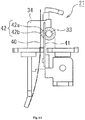
- Fig. 12 to Fig. 15 show a conventional thermal overload relay which is switchable between manual reset and automatic reset (see for example Patent Reference 1).
- this thermal overload relay comprises a bimetal member 2 which undergoes curving displacement due to heat generation caused by current conduction, and contact points 5 and 6 which cause the reversal mechanism 4 to perform a reversal operation and switch when the displacement position of the bimetal member 2 exceeds a stipulated value.
- a fixed constant point 5b of a normally closed contact 5 is mounted on the tip of a fixed contact point leaf spring 5a cantilever-supported by the case 1; this fixed contact point 5b is in contact with a movable contact point 5c mounted on the reversal plate 12.
- a fixed contact point 6b of a normally open contact 6 is mounted on the tip of a fixed contact point leaf spring 6a cantilever-supported in the proximity of the upper face of the case 1; and a movable contact point 6d is mounted on the tip of a movable contact point leaf spring 6c cantilever-supported substantially parallel to the fixed contact point leaf spring 6a, so as to oppose the fixed contact point leaf spring 6a.
- the release lever 9 When the bimetal member 2 curves and is displaced due to heat generated by a passing current, the release lever 9 is rotated in the counterclockwise direction, the rotation of this release lever 9 rotates the tension spring 13 and reversal plate 12 in the counterclockwise direction, and as shown in Fig. 13 , the normally closed contact 5 (5b, 5c) is opened, and the normally open contact 6 (6b, 6d) is closed, to enter the tripped state.
- the release lever 9, reversal plate 12, tension spring 13, normally closed contact 5 and normally open contact 6 constitute the reversal mechanism 4.
- the reset rod 16 is a cylindrical member with a step comprising a large-diameter head portion 16a and a small-diameter shaft portion 16b, and as shown in Fig. 16 , is mounted in a reset rod holding hole 3 provided in the case 1 so as to enable sliding in the shaft direction and also rotation.
- the reset rod holding hole 3 comprises a large-diameter hole portion 3a into the interior of which the large-diameter head portion 16a of the reset rod 16 is pushed, and a small-diameter hole portion 3b formed concentrically with this large-diameter hole portion 3a, and which slidably holds the small-diameter shaft portion 16b.
- a groove 16c into which can be inserted a flat-blade screwdriver or other tool to rotate the reset rod 16.
- an engaging piece 16d so as to protrude elastically, and in the tip at a position shifted 90° with respect to this engaging piece 16d is formed, by means of an inclined face and a vertical face, a cutout portion 16e cut out in an obtuse-angle shape.
- a leaf spring 6e integrated with the above-described fixed contact point leaf spring 6a abuts the cutout portion 16e of the reset rod 16.
- the reset rod 16 loaded into the reset rod holding hole 3 is impelled in the direction of protrusion from the case 1 by a return spring 7 comprising a compression spring inserted into the small-diameter shaft portion 16b; in Fig. 12 and Fig. 13 the reset rod 16 is in the manual reset position, and the reset rod 16, which receives the spring force of the return spring 7, is positioned in the axial direction by the engagement of the engaging piece 16d with a step portion 1a of the case 1 as shown in Fig. 12 , so that the head portion protrudes from the display cover 18 that occludes the upper face of the case 1.
- a return spring 7 comprising a compression spring inserted into the small-diameter shaft portion 16b
- the tip of a flat-blade screwdriver or other tool is inserted into the groove 16c in the reset rod 16, and after pushing in the reset rod 16 until abutment, the reset rod 16 is rotated 90° in the clockwise direction in Fig. 12 .
- the reset rod 16 which receives the spring force of the return spring 7 from the upward axial direction, is held in the pushed-in state while the engaging piece 16d engages with the step portion 1b of the case 1 and is positioned in the axial direction.
- Patent Reference 1 Japanese Patent Publication No. 4088815
- a reset rod 16 in the automatic reset position is disposed with a gap provided between the large-diameter head portion 16a and the circumferential face of the large-diameter hole portion 3a of the reset rod holding hole 3, and with a gap provided between the small-diameter shaft portion 16b and the circumferential face of the small-diameter hole portion 3b of the reset rod holding hole 3 as well, so that the entirety of the reset rod 16 tends to undergo axial runout.
- this invention was devised focusing on the above-described unresolved problem of the prior art, and has as an object the provision of a thermal overload relay in which, by restricting axial runout of the reset rod in the automatic reset position, characteristics of the reversal mechanism at the time of automatic reset are made stable.
- the thermal overload relay of one embodiment includes, within a case, a bimetal member which undergoes curving displacement due to heat generation caused by an overload current; a reversal mechanism which, when a displacement amount of the bimetal member exceeds a stipulated value, performs a reversal operation and switches a contact; a columnar reset rod which is loaded into a shaft loading portion formed in the case so as to be freely pushed in, and one end of which engages with a movable portion of the reversal mechanism when pushed in; and a return spring, the spring force of which acts on the reset rod such that the other end of the reset rod protrudes from the case, the reset rod being configured to be switchable between a manual reset position in which the reversal mechanism is manually returned to an initial state prior to reversal by performing a push-in operation, and an automatic reset position in which the pushed-in state is held by a pushing and rotating operation from this manual reset position and the reversal mechanism is automatically
- the axial runout restriction portion restricts axial runout of the reset rod being held in the automatic reset position, so that the position of the movable portion of the reversal mechanism which is engaged with one end of the reset rod is always constant, and the automatic reset characteristics by which the reversal mechanism automatically returns to the initial state can be made stable.
- a bulging portion is formed in one among an outer periphery of the reset rod and an inner wall of the shaft loading portion, and when the reset rod is held in the automatic reset position, the bulging portion abuts the other among the outer periphery of the reset rod and the inner wall of the shaft loading portion, and a pressing force is generated between the reset rod and the shaft loading portion, thereby restricting axial runout of the reset rod.
- thermal overload relay of this embodiment when the reset rod is held in the automatic reset position, because the bulging portion abuts the other among the outer periphery of the reset rod and the inner wall of the shaft loading portion, a pressing force is generated between the reset rod and the shaft loading portion, and axial runout of the reset rod is restricted, so that an axial runout restriction portion with a simple configuration can be provided.
- the axial runout restriction portion is provided in at least two locations that are mutually separated in a length direction of the reset rod, and axial runout of the reset rod is thereby restricted.
- thermal overload relay of one embodiment by providing the axial runout restriction portion in at least two locations that are mutually separated in the length direction of the reset rod, axial runout of the reset rod can be restricted still more reliably, and automatic reset characteristics can be improved.
- a direction in which the spring force of the return spring acts on the reset rod is a direction which deviates from an axial line of the reset rod.
- the return spring is a leaf spring member that is engaged at a position which does not interfere with a rotation range of the one end of the reset rod.
- thermal overload relay of one embodiment compared with a return spring comprising a coil spring disposed around the outer periphery of the reset rod such as is used in normal devices, disposition is easy even in a compact thermal overload relay in which there is little space for disposition of the return spring.
- an automatic reset engaging portion is provided on the outer periphery of the reset rod, a latching plate, which holds the reset rod in the pushed-in state by engaging with the automatic reset engaging portion when the pushed-in reset rod is rotated to the automatic reset position, is provided within the case, and abutting portions of the automatic reset engagement portion and the latching plate which mutually abut at a position where the reset rod is halted midway during rotation to the automatic reset position, are formed as inclined faces that are inclined downward toward a direction in which the reset rod is rotated to the automatic reset position, and that are in planar contact with each other.
- an axial runout restriction portion restricts axial runout of the reset rod being held at the automatic reset position, so that the position of the movable portion of the reversal mechanism engaged with one end of the reset rod is always constant, and the reversal mechanism characteristics during automatic reset can be made stable.
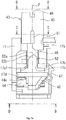
- an adjustment portion 28a of an adjustment dial 28 and a reset rod 43 the head portion 45 of which protrudes; also disposed within the insulating case 17 are an adjustment mechanism 20 which is driven by displacement of a shifter 19 engaged with one end of a main bimetal member 18, and a reversal mechanism 21 contacts of which are switched by operation of the adjustment mechanism 20.
- the adjustment mechanism 20 comprises an adjustment link 22, release lever 23 rotatably supported by the adjustment link 22, and temperature compensation bimetal member 24, fixed to the release lever 23 and engaged with the shifter 19.
- the adjustment link 22 comprises a link support portion 25 which supports the release lever 23, and a leg portion 26 extending downward from one side of the link support portion 25.
- the link support portion 25 comprises a pair of opposing plates 25a in the upper portions of which bearing holes 25a1 are formed, and which are mutually opposed, and a connecting plate 25c, connecting the pair of opposing plates 25a, and forming an opening portion 25b.
- the leg portion 26 extends downward from one among the pair of opposing plates 25a, and in the upper portion thereof is formed a bearing hole 26a.
- the release lever 23 of the adjustment mechanism 20 comprises a base plate 23a, and a pair of bent plates 23b, 23c which are bent from the two ends of the base plate 23a in the same direction at substantially the same angle. And, on the side of one of the bent plates 23b is formed a pair of rotation shafts 23d, 23e, which are inserted into the pair of bearing holes 25a1 of the adjustment link 22.
- a reversal spring pressing portion 23f is formed at an end of one of the bent plates 23b sandwiching these rotation shafts 23d, 23e, a cam contact portion 23g is formed on the other bent plate 23c, and on the rear face of the base plate 23a on the side opposite the direction of bending of the bent plates 23b, 23c, a crimp-fixing portion 31 which crimps and fixes an end of the temperature compensation bimetal member 24 is formed.
- an eccentric cam 28b of the adjustment dial 28 provided on the upper face of the insulating case 17 abuts the cam contact portion 23g of the release lever 23, and the rotation angle of the release lever 23 is set by using the tip of a screwdriver or other tool to engage the adjustment portion 28a and rotate the adjustment dial 28, changing the position of the cam contact portion 23g abutting the peripheral face of the eccentric cam 28b, and causing minute rotation about the rotation shafts 23d, 23e.
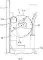
- the reversal mechanism 21 comprises a reversal mechanism support portion 32 disposed within the insulating case 17; a linking plate 34, disposed in proximity to this reversal mechanism support portion 32, and rotatably supported by a support shaft 33 provided on an inner wall of the insulating case 17; a movable plate 35, the upper portion 35b of which is slidably disposed with the lower portion 35a abutting the reversal mechanism support portion 32 as a fulcrum; and a reversal spring 36, comprising a tension coil spring stretched between an engaging hole 35c provided on the side of the upper portion 35b of the movable plate 35 and the spring support portion 32a of the reversal mechanism support portion 32 which is the lower position of the lower portion 35a.
- the linking plate 34 is provided with a first engaging pin 39a and a second engaging pin 39b, enabling engagement with the movable plate 35, and causing the linking plate 34 to rotate about the support shaft 33 together with reversal operation and return operation of the movable plate 35.
- a normally open contact (a contact) side leaf spring 37 in a state with the free end extended upward; the fixed contact point 38a of an a contact 38 is fixed to the free-end side of this leaf spring 37, and the movable contact point 38b of the a contact 38 which contacts the fixed contact point 38a is fixed to the upper portion 35b of the movable plate 35.
- the tip of the a contact-side leaf spring 37 is in contact with the basepiece 48, described below, of the reset rod 43.
- a normally closed contact (b contact) side leaf spring 40 is displaced at a position on the side opposite the a contact 38 with the linking plate 34 sandwiched therebetween, in a state with the free end extended upward, and moreover a contact support plate 41 is disposed in a state opposing this leaf spring 40.
- the free end of the leaf spring 40 is engaged with a portion of the linking plate 34, and rotates in the same direction with rotation of the linking plate 34.
- the movable contact point 42b of the b contact 42 is fixed to the free-end side of the leaf spring 40, and the fixed contact point 42a of the b contact 42 connected to the movable contact point 42b is fixed to the contact point support plate 41.
- the reset rod 43 is supported by the insulating case 17 so as to move freely in the axial direction and moreover so as to rotate freely about the axis, while being impelled by the return spring 44 disposed on the lower side of the reset rod 43 in the direction such that the head portion 45 protrudes outside from the insulating case 17.
- This reset rod 43 comprises a column-shape head portion 45; a neck portion 46, with a column shape of diameter smaller than the diameter of the head portion 45, formed coaxially with the head portion 45; a substantially disc-shape return spring engaging portion 47, formed on the end in the direction of the axis P of the neck portion 46 at a position on the side opposite the head portion 45, and engaged with the return spring 44; and a basepiece 48, formed protruding from the return spring engaging portion 47 in the axial direction in a position on the side opposite the neck portion 46.
- a groove 49 into which a flat-blade screwdriver or other tool is inserted in order to rotate the reset rod 43 substantially 90°, and in addition an indicator needle 50 which indicates the rotation position of the reset rod 43 is formed on the side peripheral face near the upper face.
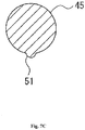
- a protrusion 51 is formed protruding on the outer periphery on the lower side of the head portion 45, extending in the direction of the axis P.
- an automatic reset engaging portion 52 to protrude as shown in Fig. 7A , and on the face directed toward the head portion 45 of this automatic reset engaging portion 52 are formed an engaging face 52a intersecting the axial direction, and an inclined face 52b, connected to this engaging face 52a and inclined downward in the direction toward the return spring engaging portion 47.
- the return spring engaging portion 47 is a region with substantially a disc shape, having a first outer peripheral face 47a formed with R1 as the radius from the axis P, and a second outer peripheral face 47b formed with a radius R2 from the axis P larger than the radius R1 of the first outer peripheral face 47a (R2 > R1).
- a basepiece 48 is formed, in a range of substantially 90°, along the first outer peripheral face 47a of the lower face of the return spring engaging face 47 (the face on the side opposite the neck portion 46); the outer peripheral face of this basepiece 48 is an inclined face, the diameter of which is reduced gradually in the direction receding from the return spring engaging portion 47.
- This basepiece 48 moves about the axis P up to the position indicated by the dot-dash line by rotating the reset rod 43 substantially 90°, that is, by rotating clockwise substantially 90° in Fig. 7D .
- the return spring 44 is a leaf spring fixed in a cantilevered state to a supporting wall 17e provided within the insulating case 17; the spring tip 44a on the free end abuts the return spring engaging portion 47, and by this means the member impels the reset rod 43 with a spring force in a direction such that the head portion 45 protrudes from the insulating case 17.
- the direction of extension of the free end of the return spring 44 is a direction deviating from the axis P, and is a direction which does not interfere with the rotation position of the basepiece 48 (the position of the basepiece 48 indicated by the solid line and dot-dash line in Fig. 7D ).
- the spring tip 44a of the return spring 44 is formed in a spherical shape protruding toward the return spring engaging portion 47.
- the protrusion 51 of the reset rod 43 and the automatic reset engaging portion 52 are formed on the opposite side in the circumferential direction (at a position separately by substantially 180° in the circumferential direction) of the indicator needle 50 formed on the head portion 45.
- the circumferential face of the head portion 45 of the reset rod 43 slidably abuts a first cutout hole 17a having a cutout portion formed in the upper portion of the insulating case 17, the circumferential face of the head portion 46 slidably abuts a second cutout hole 17c, having a cutout portion, of a latching plate 17b provided on the inside of the insulating case 17, the circumferential face of the return spring engaging portion 47 slidably abuts the lower portion of a side inner wall 17d of the insulating case 17, and the spring tip 44a of the return spring 44 abuts and impels with a spring force the return spring engaging portion 47; by this means the head portion 45 is disposed in the manual reset position so as to protrude from and enable pushing-into the insulating case 17.
- a tip 37a of the a contact side leaf spring 37 comprised by the above-described reversal mechanism 21 is in contact with the inclined face (outer peripheral face) of the basepiece 48 of the reset rod 43 disposed in the manual reset position (see Fig. 1 ).
- a reset rod return inclined face 17c1 with a downward inclination in the direction toward the return spring engaging portion 47, is provided in the opening rim in the radial direction of the second cutout hole 17c formed in the latching plate 17b of the insulating case 17; when the reset rod 43 which is to be set is halted midway during rotation to the automatic reset position, the inclined face 52b of the automatic reset engaging portion 52 of the reset rod 43 which has moved upward makes planar contact with the reset rod return inclined face 17c1.
- the case of this invention corresponds to the insulating case 17, the inclined face of this invention corresponds to the reset rod return inclined face 17c1, the bimetal member of this invention corresponds to the main bimetal member 18, the reset rod other end of this invention corresponds to the neck portion 46, the bulging portion of this invention corresponds to the second outer peripheral face 47b, the one end of the reset rod of this invention corresponds to the basepiece 48, and the bulging portion of this invention corresponds to the protrusion 51.
- the movable plate 35 When rotation of the release lever 23 in the clockwise direction advances, and the pressing force of the reversal spring pressing portion 23f exceeds the spring force of the reversal spring 36, the movable plate 35 performs a reversal operation with the lower portion 35a as a fulcrum. Together with this reversal operation of the movable plate 35, the reversal operation of the movable plate 35 is transmitted via the first engaging pin 39a to the linking plate 34, which also rotates about the support shaft 33.
- the fixed contact point 38a and movable contact point 38b of the a contact 38 which had been in the open state of Fig. 5A , come into contact (see Fig. 5B ), the fixed contact point 42a and movable contact point 42b of the b contact 42, which had been in the closed state of Fig. 6A , are separated (see Fig. 6B ), so that the contacts of the reversal mechanism 21 are switched, and the thermal overload relay enters the tripped state.
- an electromagnetic contactor (not shown) connected to the main circuit is caused to perform a circuit-opening operation, shutting off the overload current.
- the thermal overload relay When the thermal overload relay enters the tripped state and the overload current of the electromagnetic contactor is shut off, after a prescribed time has elapsed, the curving of the cooled main bimetal member 18 is corrected, and the member returns to its initial state.
- the reversal mechanism 21, the contacts of which have switched does not return to the initial state (in which the fixed contact point 38a and movable contact point 38b of the a contact 38 are in the open state, and the fixed contact point 42a and movable contact point 42b of the b contact 42 are in the closed state) unless a reset operation is applied.
- the basepiece 48 moves downward, so that the a contact side leaf spring 37 which is in contact with the inclined face of the basepiece 48 rides up onto and makes contact with the return spring engaging portion 47 while pressing the movable plate 35 in the reversed state.
- the movable plate 35 in the reversed state moves to the side of the initial position, and when the action of the reversal spring 36 exceeds the dead point, the movable plate 35 performs the return operation.
- the thermal overload relay returns to the initial state (with the fixed contact point 38a and movable contact point 38b of the a contact 38 in the open state, and the fixed contact point 42a and movable contact point 42b of the b contact 42 in the closed state).
- Figs. 9A and 9B first the tip of a flat-blade screwdriver or other tool is inserted into the groove 49 of the reset rod 43, and after pressing-in until the head portion 45 collides with the latching plate 17b, the reset rod 43 is rotated 90° in the clockwise direction.
- the indicator needle 50 of the pushed-in reset rod 43 is directed rightward in the figure, and the protrusion 51 and automatic reset engaging portion 52, which are positioned on the side opposite the indicator needle 50 in the circumferential direction, move to the side of the side inner wall 17d of the insulating case 17.
- the basepiece 48 By pushing-in the reset rod 43 and rotating 90° in the clockwise direction, the basepiece 48, while moving downward, rotates to a position which does not interfere with the return spring 44.
- the a contact side leaf spring 37 which is in contact with the inclined face of the basepiece 48, enters a state of riding up onto the return spring engaging portion 47, and moves to a position in proximity to the movable plate 35.
- the protrusion 51 of the reset rod 43 acts with a pressing force F1 on the upper portion of the side inner wall 17d of the insulating case 17, as shown in Fig. 9B , so that the reset rod 43 itself receives the reaction force to the pressing force F1, the return spring engaging portion 47 acts with a pressing force F2 on the lower portion of the side inner wall 17d of the insulating case 17, and the neck portion 46 acts with a pressing force F3 on the second cutout hole 17c of the latching plate 17b.
- the reset rod 43 set in the automatic reset position acts with pressing forces F1, F2 on the same direction on both ends in the length direction, and while the center portion in the length direction acts with a pressing force F3 in the direction opposite the pressing forces F1, F2, the reset rod 43 is set in the insulating case 17, so that axial runout is restricted.
- the reset rod 43 in the automatic reset position is impelled by the spring force of the return spring 44 from a direction deviating from the axis P, so that a force acts to rotate the reset rod 43 in a prescribed direction.
- a force occurs which presses the reset rod 43 in the automatic reset position, and axial runout of the reset rod 43 is further restricted, so that the automatic reset characteristic stability can be improved.
- the return spring 44 is a leaf spring which is disposed and extended to the lower-face side of the return spring engaging portion 47 so as not to interfere with the rotation position (see Fig. 7D ) of the basepiece 48; compared with a return spring comprising a coil spring disposed on the outer periphery of the reset rod, such as is used in ordinary devices, disposition is easy even in a compact thermal overload relay in which there is little space for disposition of a return spring 44.
- a spherical shape is formed on the tip 44a of the return spring 44, and the contact area of the tip 44a in contact with the lower face of the return spring engaging portion 47 is set to be small, in a structure in which sliding friction between the return spring engaging portion 47 and the contact portion of the return spring 44 is reduced, so that operation of the reset rod 43 is not impeded.
- a case is explained in which an operation of setting the reset rod 43 from the manual reset position to the automatic reset position is halted midway.
- the automatic reset engaging portion 52 passes through the cutout portion of the second cutout hole 17c, and is positioned above the latching plate 17b; by this means, the head portion 45 of the reset rod 43 returns to the manual reset position protruding from the insulating case 17.
- axial runout of the reset rod in the automatic reset position is restricted, so that the characteristics of the reversal mechanism during automatic reset can be made stable.
Landscapes
- Breakers (AREA)
- Fuses (AREA)
Claims (5)
- Thermisches Überlastrelais, das innerhalb eines Gehäuses (17) Folgendes umfasst:ein Bimetallelement (18), welches aufgrund von Wärmeerzeugung, welche durch einen Überlaststrom bewirkt wird, einen Bogenversatz erfährt;einen Umkehrmechanismus (21, 35), welcher, wenn ein Versatzbetrag des Bimetallelements (18) einen bestimmten Wert überschreitet, eine Umkehroperation durchführt und einen Kontakt (38, 42) schaltet;einen säulenförmigen Rücksetzstab (43), welcher in einen Schaftladabschnitt geladen ist, welcher in dem Gehäuse (17) ausgebildet ist, um frei hineingedrückt zu werden, und dessen eines Ende mit einem beweglichen Abschnitt (35) des Umkehrmechanismus (21) in Eingriff gebracht wird, wenn er hineingedrückt wird; undeine Rückzugfeder (44), deren Federkraft derartig auf den Rücksetzstab (43) wirkt, dass das andere Ende des Rücksetzstabs (43) aus dem Gehäuse (17) vorsteht,wobei der Rücksetzstab (43) so konfiguriert ist, dass er zwischen einer manuellen Rücksetzposition, bei welcher der Umkehrmechanismus (21) vor der Umkehrung durch Durchführen einer Hineindrückoperation manuell auf einen Anfangszustand zurückgebracht wird, und einer automatischen Rücksetzposition schaltbar ist, bei welcher der hineingedrückte Zustand durch eine Drücken-und-Drehen-Operation aus dieser manuellen Rücksetzposition gehalten wird, und der Umkehrmechanismus (21) automatisch in den Anfangszustand zurückgebracht wird,wobei das thermische Überlastrelais dadurch gekennzeichnet ist, dass ein axialer Unwuchtbegrenzungsabschnitt (51, 52, 47b), welche eine axiale Unwucht des Rücksetzstabs (43) begrenzt, wenn der Rücksetzstab (43) in der automatischen Rücksetzposition gehalten wird, bereitgestellt wird, wobeiein ausgebauchter Abschnitt (51, 52) an einem Element unter einer äußeren Peripherie des Rücksetzstabs (43) und einer Innenwand des Schaftladeabschnitts ausgebildet ist, undwenn der Rücksetzstab (43) in der automatischen Rücksetzposition gehalten wird, der ausgebauchte Abschnitt (51, 52) an dem anderen Element unter der äußeren Peripherie des Rücksetzstabs (43) und der Innenwand des Schaftladeabschnitts angrenzt und eine Andruckkraft (F1, F3, F2) zwischen dem Rücksetzstab (43) und dem Schaftladeabschnitt erzeugt wird, wodurch eine axiale Unwucht des Rücksetzstabs (43) begrenzt wird.
- Thermisches Überlastrelais nach Anspruch 1, dadurch gekennzeichnet, dass der axiale Unwuchtbegrenzungsabschnitt (51, 52, 47b) an mindestens zwei Orten bereitgestellt ist, welche in einer Längsrichtung (P) des Rücksetzstabs (43) voneinander getrennt sind, und wodurch eine axiale Unwucht des Rücksetzstabs (43) begrenzt ist.
- Thermisches Überlastrelais nach Anspruch 1 oder 2, dadurch gekennzeichnet, dass eine Richtung, in welche die Federkraft der Rückzugfeder (44) auf den Rücksetzstab (43) wirkt, eine Richtung ist, welche von einer axialen Linie des Rücksetzstabs (43) abweicht.
- Thermisches Überlastrelais nach Anspruch 3, dadurch gekennzeichnet, dass die Rückzugfeder (44) ein Blattfederelement ist, welches an einer Position eingreift, welche einen Rotationsbereich des einen Endes des Rücksetzstabs (43) nicht stört.
- Thermisches Überlastrelais nach einem der Ansprüche 1 bis 4, dadurch gekennzeichnet, dass
ein automatischer Rücksetz-Eingriffsabschnitt (52) auf der äußeren Peripherie des Rücksetzstabs (43) bereitgestellt ist,
eine Verriegelungsplatte (17b), welche den Rücksetzstab (43) durch Eingreifen in den automatischen Rücksetz-Eingriffsabschnitt (52) in dem hineingedrückten Zustand hält, wenn der hineingedrückte Rücksetzstab (43) in die automatische Rücksetzposition gedreht ist, innerhalb des Gehäuses (17) bereitgestellt ist, und
Stoßabschnitte (17c1, 52b) des automatischen Rücksetz-Eingriffsabschnitts (52) und die Verriegelungsplatte (17b), welche in einer Position aneinander angrenzen, in welcher der Rücksetzstab (43) auf halbem Wege während einer Rotation in die automatische Rücksetzposition angehalten wird, als geneigte Flächen ausgebildet sind, welche in eine Richtung abwärts geneigt sind, in welche der Rücksetzstab (43) in die automatische Rücksetzposition gedreht wird, und welche in planarem Kontakt zueinander sind.
Applications Claiming Priority (2)
| Application Number | Priority Date | Filing Date | Title |
|---|---|---|---|
| JP2009244394A JP4978681B2 (ja) | 2009-10-23 | 2009-10-23 | 熱動形過負荷継電器 |
| PCT/JP2010/004739 WO2011048732A1 (ja) | 2009-10-23 | 2010-07-26 | 熱動形過負荷継電器 |
Publications (3)
| Publication Number | Publication Date |
|---|---|
| EP2492943A1 EP2492943A1 (de) | 2012-08-29 |
| EP2492943A4 EP2492943A4 (de) | 2015-01-21 |
| EP2492943B1 true EP2492943B1 (de) | 2018-04-04 |
Family
ID=43899977
Family Applications (1)
| Application Number | Title | Priority Date | Filing Date |
|---|---|---|---|
| EP10824587.9A Not-in-force EP2492943B1 (de) | 2009-10-23 | 2010-07-26 | Durch wärme bewegtes überlastrelais |
Country Status (5)
| Country | Link |
|---|---|
| US (1) | US9111709B2 (de) |
| EP (1) | EP2492943B1 (de) |
| JP (1) | JP4978681B2 (de) |
| CN (1) | CN102473558B (de) |
| WO (1) | WO2011048732A1 (de) |
Families Citing this family (3)
| Publication number | Priority date | Publication date | Assignee | Title |
|---|---|---|---|---|
| JP4978681B2 (ja) * | 2009-10-23 | 2012-07-18 | 富士電機機器制御株式会社 | 熱動形過負荷継電器 |
| JP7466845B2 (ja) * | 2021-06-18 | 2024-04-15 | 株式会社オートネットワーク技術研究所 | 回路構成体 |
| CN116157890A (zh) * | 2021-07-02 | 2023-05-23 | 富士电机机器制御株式会社 | 热动型过载继电器 |
Family Cites Families (37)
| Publication number | Priority date | Publication date | Assignee | Title |
|---|---|---|---|---|
| GB1250773A (de) * | 1968-11-23 | 1971-10-20 | ||
| GB1399401A (en) * | 1972-01-11 | 1975-07-02 | Cutler Hammer Inc | Electric switches |
| US3792401A (en) * | 1972-06-29 | 1974-02-12 | Westinghouse Electric Corp | Thermally responsive electrical device |
| US4047140A (en) * | 1975-12-23 | 1977-09-06 | Westinghouse Electric Corporation | Thermal overload relay |
| GB1595046A (en) * | 1978-04-25 | 1981-08-05 | Sprecher & Schuh Ag | Bimetallic thermo-release |
| US4270113A (en) * | 1979-04-06 | 1981-05-26 | Westinghouse Electric Corp. | Thermal overload relay |
| DE2914776C2 (de) * | 1979-04-11 | 1981-07-02 | Siemens AG, 1000 Berlin und 8000 München | Auslöser für ein thermisches Schutzrelais |
| CH662211A5 (de) * | 1982-03-22 | 1987-09-15 | Sprecher & Schuh Ag | Verfahren zum herstellen eines mehrphasigen thermischen ausloesers sowie ein nach diesem verfahren hergestellter ausloeser. |
| EP0164690B1 (de) * | 1984-06-06 | 1989-10-18 | Mitsubishi Denki Kabushiki Kaisha | Thermisch wirkendes Uberstromrelais |
| US4528539A (en) * | 1984-06-28 | 1985-07-09 | Eaton Corporation | Reduced-size thermal overload relay |
| US4642598A (en) * | 1984-12-28 | 1987-02-10 | Fuji Electric Co., Ltd. | Adjusting device for thermal overload relay |
| JPH0347242Y2 (de) * | 1985-03-26 | 1991-10-08 | ||
| JPS61230228A (ja) * | 1985-04-05 | 1986-10-14 | 富士電機株式会社 | 熱形過負荷継電器 |
| JPH0679460B2 (ja) * | 1986-05-22 | 1994-10-05 | 三菱電機株式会社 | 熱動形過電流継電器 |
| DE8619694U1 (de) * | 1986-07-23 | 1986-09-18 | Siemens AG, 1000 Berlin und 8000 München | Überlastrelais |
| JPS6365936U (de) * | 1986-10-17 | 1988-04-30 | ||
| JPS6365938U (de) * | 1986-10-17 | 1988-04-30 | ||
| JPH069432Y2 (ja) * | 1986-10-17 | 1994-03-09 | 三菱電機株式会社 | 熱動式過電流継電器 |
| KR900007372B1 (ko) * | 1986-11-26 | 1990-10-08 | 미쓰비시뎅끼 가부시끼가이샤 | 열동식 과전류 계전기 |
| US4908594A (en) * | 1987-07-14 | 1990-03-13 | Fuji Electric Co., Ltd. | Thermal overload relay |
| JPH071665B2 (ja) * | 1988-09-20 | 1995-01-11 | 富士電機株式会社 | 熱形過負荷継電器の反転ばね機構 |
| JP2809963B2 (ja) * | 1993-03-09 | 1998-10-15 | 三菱電機エンジニアリング株式会社 | 過電流継電器 |
| JP3899754B2 (ja) * | 1999-12-01 | 2007-03-28 | 富士電機機器制御株式会社 | 熱動形過負荷継電器 |
| JP4186415B2 (ja) * | 2000-11-30 | 2008-11-26 | 富士電機機器制御株式会社 | 回路しゃ断器の過負荷引外し装置 |
| JP4088815B2 (ja) * | 2000-12-01 | 2008-05-21 | 富士電機機器制御株式会社 | 熱動形過負荷継電器 |
| JP2002237246A (ja) * | 2001-02-13 | 2002-08-23 | Fuji Electric Co Ltd | 熱動形過負荷継電器 |
| JP2003217397A (ja) | 2002-01-25 | 2003-07-31 | Matsushita Electric Ind Co Ltd | 回転操作型電子部品 |
| DE10296638T5 (de) * | 2002-03-28 | 2004-04-22 | Mitsubishi Denki K.K. | Thermisches Überstromrelais |
| KR100881365B1 (ko) * | 2007-08-07 | 2009-02-02 | 엘에스산전 주식회사 | 열동형 과부하 보호장치의 트립 감도 조정 방법 |
| KR100905021B1 (ko) * | 2007-08-07 | 2009-06-30 | 엘에스산전 주식회사 | 열동형 과부하 트립 장치 및 그의 트립 감도 조정 방법 |
| JP2009224311A (ja) * | 2008-02-19 | 2009-10-01 | Fuji Electric Fa Components & Systems Co Ltd | 熱動形過負荷継電器 |
| JP4706772B2 (ja) * | 2009-03-27 | 2011-06-22 | 富士電機機器制御株式会社 | 熱動形過負荷継電器 |
| JP4906881B2 (ja) * | 2009-03-27 | 2012-03-28 | 富士電機機器制御株式会社 | 熱動形過負荷継電器 |
| JP5152102B2 (ja) * | 2009-03-27 | 2013-02-27 | 富士電機機器制御株式会社 | 熱動形過負荷継電器 |
| JP4798243B2 (ja) * | 2009-03-27 | 2011-10-19 | 富士電機機器制御株式会社 | 熱動形過負荷継電器 |
| JP2010232058A (ja) * | 2009-03-27 | 2010-10-14 | Fuji Electric Fa Components & Systems Co Ltd | 熱動形過負荷継電器 |
| JP4978681B2 (ja) * | 2009-10-23 | 2012-07-18 | 富士電機機器制御株式会社 | 熱動形過負荷継電器 |
-
2009
- 2009-10-23 JP JP2009244394A patent/JP4978681B2/ja active Active
-
2010
- 2010-07-26 WO PCT/JP2010/004739 patent/WO2011048732A1/ja not_active Ceased
- 2010-07-26 CN CN201080036032.7A patent/CN102473558B/zh active Active
- 2010-07-26 EP EP10824587.9A patent/EP2492943B1/de not_active Not-in-force
- 2010-07-26 US US13/389,740 patent/US9111709B2/en not_active Expired - Fee Related
Non-Patent Citations (1)
| Title |
|---|
| None * |
Also Published As
| Publication number | Publication date |
|---|---|
| EP2492943A4 (de) | 2015-01-21 |
| CN102473558A (zh) | 2012-05-23 |
| WO2011048732A1 (ja) | 2011-04-28 |
| CN102473558B (zh) | 2014-10-15 |
| EP2492943A1 (de) | 2012-08-29 |
| US9111709B2 (en) | 2015-08-18 |
| JP4978681B2 (ja) | 2012-07-18 |
| JP2011090936A (ja) | 2011-05-06 |
| US20120161918A1 (en) | 2012-06-28 |
Similar Documents
| Publication | Publication Date | Title |
|---|---|---|
| EP2492943B1 (de) | Durch wärme bewegtes überlastrelais | |
| CN108022811B (zh) | 一种具有热脱扣器的断路器 | |
| EP2091060A2 (de) | Thermisch betriebenes Überstromrelais | |
| US20100245020A1 (en) | Thermal overload relay | |
| US8138879B2 (en) | Thermal overload relay | |
| JP4798243B2 (ja) | 熱動形過負荷継電器 | |
| JP5556237B2 (ja) | スイッチ | |
| US7495189B2 (en) | Miniature circuit breaker | |
| JP6255664B2 (ja) | 熱動形過負荷継電器 | |
| CN101847547B (zh) | 热动型过载继电器 | |
| CN101546676A (zh) | 热过载继电器 | |
| JP5099235B2 (ja) | 熱動形過負荷継電器 | |
| CN100442420C (zh) | 回路遮断路 | |
| KR200345665Y1 (ko) | 열동형 과부하 계전기 | |
| KR200208215Y1 (ko) | 열동형 과부하 계전기의 반전기구 | |
| JP3205633B2 (ja) | サーキットプロテクタ | |
| JPH0628763Y2 (ja) | 熱動式過電流継電器 | |
| JPH11306947A (ja) | 熱動形過負荷継電器 | |
| JPH04115742U (ja) | サーマルリレー | |
| JPH04115743U (ja) | サーマルリレー |
Legal Events
| Date | Code | Title | Description |
|---|---|---|---|
| PUAI | Public reference made under article 153(3) epc to a published international application that has entered the european phase |
Free format text: ORIGINAL CODE: 0009012 |
|
| 17P | Request for examination filed |
Effective date: 20120208 |
|
| AK | Designated contracting states |
Kind code of ref document: A1 Designated state(s): AL AT BE BG CH CY CZ DE DK EE ES FI FR GB GR HR HU IE IS IT LI LT LU LV MC MK MT NL NO PL PT RO SE SI SK SM TR |
|
| DAX | Request for extension of the european patent (deleted) | ||
| A4 | Supplementary search report drawn up and despatched |
Effective date: 20141223 |
|
| RIC1 | Information provided on ipc code assigned before grant |
Ipc: H01H 61/01 20060101AFI20141217BHEP |
|
| GRAP | Despatch of communication of intention to grant a patent |
Free format text: ORIGINAL CODE: EPIDOSNIGR1 |
|
| INTG | Intention to grant announced |
Effective date: 20171025 |
|
| GRAS | Grant fee paid |
Free format text: ORIGINAL CODE: EPIDOSNIGR3 |
|
| GRAA | (expected) grant |
Free format text: ORIGINAL CODE: 0009210 |
|
| AK | Designated contracting states |
Kind code of ref document: B1 Designated state(s): AL AT BE BG CH CY CZ DE DK EE ES FI FR GB GR HR HU IE IS IT LI LT LU LV MC MK MT NL NO PL PT RO SE SI SK SM TR |
|
| REG | Reference to a national code |
Ref country code: GB Ref legal event code: FG4D |
|
| REG | Reference to a national code |
Ref country code: CH Ref legal event code: EP |
|
| REG | Reference to a national code |
Ref country code: AT Ref legal event code: REF Ref document number: 986448 Country of ref document: AT Kind code of ref document: T Effective date: 20180415 |
|
| REG | Reference to a national code |
Ref country code: IE Ref legal event code: FG4D |
|
| REG | Reference to a national code |
Ref country code: DE Ref legal event code: R096 Ref document number: 602010049739 Country of ref document: DE |
|
| REG | Reference to a national code |
Ref country code: FR Ref legal event code: PLFP Year of fee payment: 9 |
|
| REG | Reference to a national code |
Ref country code: NL Ref legal event code: MP Effective date: 20180404 |
|
| REG | Reference to a national code |
Ref country code: LT Ref legal event code: MG4D |
|
| PG25 | Lapsed in a contracting state [announced via postgrant information from national office to epo] |
Ref country code: NL Free format text: LAPSE BECAUSE OF FAILURE TO SUBMIT A TRANSLATION OF THE DESCRIPTION OR TO PAY THE FEE WITHIN THE PRESCRIBED TIME-LIMIT Effective date: 20180404 |
|
| PG25 | Lapsed in a contracting state [announced via postgrant information from national office to epo] |
Ref country code: ES Free format text: LAPSE BECAUSE OF FAILURE TO SUBMIT A TRANSLATION OF THE DESCRIPTION OR TO PAY THE FEE WITHIN THE PRESCRIBED TIME-LIMIT Effective date: 20180404 Ref country code: LT Free format text: LAPSE BECAUSE OF FAILURE TO SUBMIT A TRANSLATION OF THE DESCRIPTION OR TO PAY THE FEE WITHIN THE PRESCRIBED TIME-LIMIT Effective date: 20180404 Ref country code: PL Free format text: LAPSE BECAUSE OF FAILURE TO SUBMIT A TRANSLATION OF THE DESCRIPTION OR TO PAY THE FEE WITHIN THE PRESCRIBED TIME-LIMIT Effective date: 20180404 Ref country code: FI Free format text: LAPSE BECAUSE OF FAILURE TO SUBMIT A TRANSLATION OF THE DESCRIPTION OR TO PAY THE FEE WITHIN THE PRESCRIBED TIME-LIMIT Effective date: 20180404 Ref country code: BG Free format text: LAPSE BECAUSE OF FAILURE TO SUBMIT A TRANSLATION OF THE DESCRIPTION OR TO PAY THE FEE WITHIN THE PRESCRIBED TIME-LIMIT Effective date: 20180704 Ref country code: NO Free format text: LAPSE BECAUSE OF FAILURE TO SUBMIT A TRANSLATION OF THE DESCRIPTION OR TO PAY THE FEE WITHIN THE PRESCRIBED TIME-LIMIT Effective date: 20180704 Ref country code: SE Free format text: LAPSE BECAUSE OF FAILURE TO SUBMIT A TRANSLATION OF THE DESCRIPTION OR TO PAY THE FEE WITHIN THE PRESCRIBED TIME-LIMIT Effective date: 20180404 Ref country code: AL Free format text: LAPSE BECAUSE OF FAILURE TO SUBMIT A TRANSLATION OF THE DESCRIPTION OR TO PAY THE FEE WITHIN THE PRESCRIBED TIME-LIMIT Effective date: 20180404 |
|
| PG25 | Lapsed in a contracting state [announced via postgrant information from national office to epo] |
Ref country code: HR Free format text: LAPSE BECAUSE OF FAILURE TO SUBMIT A TRANSLATION OF THE DESCRIPTION OR TO PAY THE FEE WITHIN THE PRESCRIBED TIME-LIMIT Effective date: 20180404 Ref country code: GR Free format text: LAPSE BECAUSE OF FAILURE TO SUBMIT A TRANSLATION OF THE DESCRIPTION OR TO PAY THE FEE WITHIN THE PRESCRIBED TIME-LIMIT Effective date: 20180705 Ref country code: LV Free format text: LAPSE BECAUSE OF FAILURE TO SUBMIT A TRANSLATION OF THE DESCRIPTION OR TO PAY THE FEE WITHIN THE PRESCRIBED TIME-LIMIT Effective date: 20180404 |
|
| REG | Reference to a national code |
Ref country code: AT Ref legal event code: MK05 Ref document number: 986448 Country of ref document: AT Kind code of ref document: T Effective date: 20180404 |
|
| PG25 | Lapsed in a contracting state [announced via postgrant information from national office to epo] |
Ref country code: PT Free format text: LAPSE BECAUSE OF FAILURE TO SUBMIT A TRANSLATION OF THE DESCRIPTION OR TO PAY THE FEE WITHIN THE PRESCRIBED TIME-LIMIT Effective date: 20180806 |
|
| REG | Reference to a national code |
Ref country code: DE Ref legal event code: R097 Ref document number: 602010049739 Country of ref document: DE |
|
| PG25 | Lapsed in a contracting state [announced via postgrant information from national office to epo] |
Ref country code: SK Free format text: LAPSE BECAUSE OF FAILURE TO SUBMIT A TRANSLATION OF THE DESCRIPTION OR TO PAY THE FEE WITHIN THE PRESCRIBED TIME-LIMIT Effective date: 20180404 Ref country code: RO Free format text: LAPSE BECAUSE OF FAILURE TO SUBMIT A TRANSLATION OF THE DESCRIPTION OR TO PAY THE FEE WITHIN THE PRESCRIBED TIME-LIMIT Effective date: 20180404 Ref country code: DK Free format text: LAPSE BECAUSE OF FAILURE TO SUBMIT A TRANSLATION OF THE DESCRIPTION OR TO PAY THE FEE WITHIN THE PRESCRIBED TIME-LIMIT Effective date: 20180404 Ref country code: EE Free format text: LAPSE BECAUSE OF FAILURE TO SUBMIT A TRANSLATION OF THE DESCRIPTION OR TO PAY THE FEE WITHIN THE PRESCRIBED TIME-LIMIT Effective date: 20180404 Ref country code: CZ Free format text: LAPSE BECAUSE OF FAILURE TO SUBMIT A TRANSLATION OF THE DESCRIPTION OR TO PAY THE FEE WITHIN THE PRESCRIBED TIME-LIMIT Effective date: 20180404 Ref country code: AT Free format text: LAPSE BECAUSE OF FAILURE TO SUBMIT A TRANSLATION OF THE DESCRIPTION OR TO PAY THE FEE WITHIN THE PRESCRIBED TIME-LIMIT Effective date: 20180404 |
|
| PLBE | No opposition filed within time limit |
Free format text: ORIGINAL CODE: 0009261 |
|
| STAA | Information on the status of an ep patent application or granted ep patent |
Free format text: STATUS: NO OPPOSITION FILED WITHIN TIME LIMIT |
|
| PG25 | Lapsed in a contracting state [announced via postgrant information from national office to epo] |
Ref country code: SM Free format text: LAPSE BECAUSE OF FAILURE TO SUBMIT A TRANSLATION OF THE DESCRIPTION OR TO PAY THE FEE WITHIN THE PRESCRIBED TIME-LIMIT Effective date: 20180404 Ref country code: IT Free format text: LAPSE BECAUSE OF FAILURE TO SUBMIT A TRANSLATION OF THE DESCRIPTION OR TO PAY THE FEE WITHIN THE PRESCRIBED TIME-LIMIT Effective date: 20180404 |
|
| REG | Reference to a national code |
Ref country code: CH Ref legal event code: PL |
|
| 26N | No opposition filed |
Effective date: 20190107 |
|
| GBPC | Gb: european patent ceased through non-payment of renewal fee |
Effective date: 20180726 |
|
| PG25 | Lapsed in a contracting state [announced via postgrant information from national office to epo] |
Ref country code: MC Free format text: LAPSE BECAUSE OF FAILURE TO SUBMIT A TRANSLATION OF THE DESCRIPTION OR TO PAY THE FEE WITHIN THE PRESCRIBED TIME-LIMIT Effective date: 20180404 Ref country code: LU Free format text: LAPSE BECAUSE OF NON-PAYMENT OF DUE FEES Effective date: 20180726 |
|
| REG | Reference to a national code |
Ref country code: BE Ref legal event code: MM Effective date: 20180731 |
|
| REG | Reference to a national code |
Ref country code: IE Ref legal event code: MM4A |
|
| PG25 | Lapsed in a contracting state [announced via postgrant information from national office to epo] |
Ref country code: LI Free format text: LAPSE BECAUSE OF NON-PAYMENT OF DUE FEES Effective date: 20180731 Ref country code: CH Free format text: LAPSE BECAUSE OF NON-PAYMENT OF DUE FEES Effective date: 20180731 Ref country code: IE Free format text: LAPSE BECAUSE OF NON-PAYMENT OF DUE FEES Effective date: 20180726 Ref country code: GB Free format text: LAPSE BECAUSE OF NON-PAYMENT OF DUE FEES Effective date: 20180726 |
|
| PG25 | Lapsed in a contracting state [announced via postgrant information from national office to epo] |
Ref country code: BE Free format text: LAPSE BECAUSE OF NON-PAYMENT OF DUE FEES Effective date: 20180731 Ref country code: SI Free format text: LAPSE BECAUSE OF FAILURE TO SUBMIT A TRANSLATION OF THE DESCRIPTION OR TO PAY THE FEE WITHIN THE PRESCRIBED TIME-LIMIT Effective date: 20180404 |
|
| PG25 | Lapsed in a contracting state [announced via postgrant information from national office to epo] |
Ref country code: MT Free format text: LAPSE BECAUSE OF NON-PAYMENT OF DUE FEES Effective date: 20180726 |
|
| PG25 | Lapsed in a contracting state [announced via postgrant information from national office to epo] |
Ref country code: TR Free format text: LAPSE BECAUSE OF FAILURE TO SUBMIT A TRANSLATION OF THE DESCRIPTION OR TO PAY THE FEE WITHIN THE PRESCRIBED TIME-LIMIT Effective date: 20180404 |
|
| PG25 | Lapsed in a contracting state [announced via postgrant information from national office to epo] |
Ref country code: HU Free format text: LAPSE BECAUSE OF FAILURE TO SUBMIT A TRANSLATION OF THE DESCRIPTION OR TO PAY THE FEE WITHIN THE PRESCRIBED TIME-LIMIT; INVALID AB INITIO Effective date: 20100726 |
|
| PG25 | Lapsed in a contracting state [announced via postgrant information from national office to epo] |
Ref country code: MK Free format text: LAPSE BECAUSE OF NON-PAYMENT OF DUE FEES Effective date: 20180404 Ref country code: CY Free format text: LAPSE BECAUSE OF FAILURE TO SUBMIT A TRANSLATION OF THE DESCRIPTION OR TO PAY THE FEE WITHIN THE PRESCRIBED TIME-LIMIT Effective date: 20180404 |
|
| PG25 | Lapsed in a contracting state [announced via postgrant information from national office to epo] |
Ref country code: IS Free format text: LAPSE BECAUSE OF FAILURE TO SUBMIT A TRANSLATION OF THE DESCRIPTION OR TO PAY THE FEE WITHIN THE PRESCRIBED TIME-LIMIT Effective date: 20180804 |
|
| PGFP | Annual fee paid to national office [announced via postgrant information from national office to epo] |
Ref country code: FR Payment date: 20210611 Year of fee payment: 12 |
|
| PGFP | Annual fee paid to national office [announced via postgrant information from national office to epo] |
Ref country code: DE Payment date: 20210629 Year of fee payment: 12 |
|
| REG | Reference to a national code |
Ref country code: DE Ref legal event code: R081 Ref document number: 602010049739 Country of ref document: DE Owner name: FUJI ELECTRIC FA COMPONENTS & SYSTEMS CO., LTD, JP Free format text: FORMER OWNER: FUJI ELECTRIC FA COMPONENTS & SYSTEMS CO., LTD., TOKYO, JP |
|
| REG | Reference to a national code |
Ref country code: DE Ref legal event code: R119 Ref document number: 602010049739 Country of ref document: DE |
|
| PG25 | Lapsed in a contracting state [announced via postgrant information from national office to epo] |
Ref country code: FR Free format text: LAPSE BECAUSE OF NON-PAYMENT OF DUE FEES Effective date: 20220731 |
|
| PG25 | Lapsed in a contracting state [announced via postgrant information from national office to epo] |
Ref country code: DE Free format text: LAPSE BECAUSE OF NON-PAYMENT OF DUE FEES Effective date: 20230201 |