EP2091060A2 - Thermisch betriebenes Überstromrelais - Google Patents
Thermisch betriebenes Überstromrelais Download PDFInfo
- Publication number
- EP2091060A2 EP2091060A2 EP08017805A EP08017805A EP2091060A2 EP 2091060 A2 EP2091060 A2 EP 2091060A2 EP 08017805 A EP08017805 A EP 08017805A EP 08017805 A EP08017805 A EP 08017805A EP 2091060 A2 EP2091060 A2 EP 2091060A2
- Authority
- EP
- European Patent Office
- Prior art keywords
- outer casing
- slider
- disk
- release lever
- adjusting dial
- Prior art date
- Legal status (The legal status is an assumption and is not a legal conclusion. Google has not performed a legal analysis and makes no representation as to the accuracy of the status listed.)
- Withdrawn
Links
Images

Classifications
-
- H—ELECTRICITY
- H01—ELECTRIC ELEMENTS
- H01H—ELECTRIC SWITCHES; RELAYS; SELECTORS; EMERGENCY PROTECTIVE DEVICES
- H01H61/00—Electrothermal relays
- H01H61/01—Details
-
- H—ELECTRICITY
- H01—ELECTRIC ELEMENTS
- H01H—ELECTRIC SWITCHES; RELAYS; SELECTORS; EMERGENCY PROTECTIVE DEVICES
- H01H37/00—Thermally-actuated switches
- H01H37/02—Details
- H01H37/62—Means other than thermal means for introducing a predetermined time delay
-
- H—ELECTRICITY
- H01—ELECTRIC ELEMENTS
- H01H—ELECTRIC SWITCHES; RELAYS; SELECTORS; EMERGENCY PROTECTIVE DEVICES
- H01H37/00—Thermally-actuated switches
- H01H37/02—Details
- H01H37/32—Thermally-sensitive members
- H01H37/46—Thermally-sensitive members actuated due to expansion or contraction of a solid
-
- H—ELECTRICITY
- H01—ELECTRIC ELEMENTS
- H01H—ELECTRIC SWITCHES; RELAYS; SELECTORS; EMERGENCY PROTECTIVE DEVICES
- H01H61/00—Electrothermal relays
- H01H61/02—Electrothermal relays wherein the thermally-sensitive member is heated indirectly, e.g. resistively, inductively
-
- H—ELECTRICITY
- H01—ELECTRIC ELEMENTS
- H01H—ELECTRIC SWITCHES; RELAYS; SELECTORS; EMERGENCY PROTECTIVE DEVICES
- H01H71/00—Details of the protective switches or relays covered by groups H01H73/00 - H01H83/00
- H01H71/10—Operating or release mechanisms
- H01H71/12—Automatic release mechanisms with or without manual release
- H01H71/14—Electrothermal mechanisms
- H01H71/16—Electrothermal mechanisms with bimetal element
- H01H71/162—Electrothermal mechanisms with bimetal element with compensation for ambient temperature
-
- H—ELECTRICITY
- H01—ELECTRIC ELEMENTS
- H01H—ELECTRIC SWITCHES; RELAYS; SELECTORS; EMERGENCY PROTECTIVE DEVICES
- H01H71/00—Details of the protective switches or relays covered by groups H01H73/00 - H01H83/00
- H01H71/74—Means for adjusting the conditions under which the device will function to provide protection
- H01H71/7427—Adjusting only the electrothermal mechanism
- H01H2071/7454—Adjusting only the electrothermal mechanism with adjustable axis of transmission lever between bimetal element and trip lever
-
- H—ELECTRICITY
- H01—ELECTRIC ELEMENTS
- H01H—ELECTRIC SWITCHES; RELAYS; SELECTORS; EMERGENCY PROTECTIVE DEVICES
- H01H71/00—Details of the protective switches or relays covered by groups H01H73/00 - H01H83/00
- H01H71/74—Means for adjusting the conditions under which the device will function to provide protection
- H01H2071/7481—Means for adjusting the conditions under which the device will function to provide protection with indexing means for magnetic or thermal tripping adjustment knob
Definitions
- the present invention relates to a thermally operated overload relay (also referred to as a thermal relay) used in combination with an electromagnetic contactor, a molded case circuit breaker, or the like.
- the present invention relates to a linkage structure between a release lever for driving a reversing spring of a contact switching mechanism and an adjusting dial for setting a rated or trigger current value, i.e., a current value at which the overload relay is to be thermally operated (triggered).
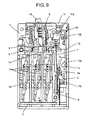
- Fig. 9 shows a typical conventional structure of a thermally operated overload relay (see for example, JP 2005-116370 A , in particular Fig. 4 thereof).
- the reference numeral 1 represents an outer casing made of a molded resin
- the reference numeral 2 represents main bimetals, one for each phase of a three phase main circuit
- the numeral 2a represents a heater
- the numeral 3 represents a shifter linked to a free end of each of the main bimetals 2
- the numeral 4 represents a compensation bimetal (for compensating the ambient temperature) connected to the release lever 5 at an upper end thereof and opposing the shifter 3, the compensation bimetal simultaneously serving as an input lever
- the numeral 6 represents a contact switching mechanism that performs a switching operation triggered by an output (a movement) of the release lever 5.
- This contact switching mechanism 6 is an assembled structure comprising a reversing spring 7 that performs a snap action by a pushing operation on the release lever 5, a slider 8 connected to an end of the reversing spring 7, and output contacts 9 (b-contact) and 10 (a-contact) that act in response to a movement of the slider 8.
- the reference numeral 11 represents an adjusting dial for setting a trigger current value;
- the numeral 12 represents an adjusting link for linking a cam portion 11 a of the adjusting dial 11 and the release lever 5;
- the numeral 13 represents a reset button for manually returning the contact switching mechanism.
- the adjusting dial 11 is disposed on the top of the outer casing 1 with a cylindrical cam portion (a tangential eccentric cam) 11a thereof projecting down into the casing.
- the adjusting link 12 is a seesaw type link that extends vertically and is pivotally supported by a main shaft 1a, which is a holder of the adjusting link 12, provided on the outer casing 1 and engaged to a bearing part 12a formed at the central region of the adjusting link 12.
- the adjusting link 12 has a cam follower 12b at the top thereof, the cam follower 12b being in contact with the outer peripheral surface of the cam portion 11 a.
- a movable shaft 12c At the bottom end of the adjusting link 12 is provided a movable shaft 12c on which an end of the release lever 5 is pivotally supported to couple rotatably the adjusting link 12 and the release lever 5.
- the release lever 5 coupled to the adjusting link 12 has an output end 5a standing up from an end of the adjusting link and opposing the actuation end 7a of the reversing spring 7. To the back surface of this output end 5a fixedly connected is the top of the compensation bimetal 4.
- the shifter 3 when the main bimetals 2 bend in response to being heated by heat generated by the heater 2a caused by the electric current flowing in the main circuit, and the shifter 3 is displaced in the direction of the arrow A corresponding to the bending of the main bimetals, the bending of the main bimetals 2 is transmitted through the shifter 3 and the compensation bimetal 4 to the release lever 5.
- the release lever 5 rotates counterclockwise (in the direction of the arrow B) around the movable shaft 12c of the adjusting link 12, and the output end 5a pushes the actuation end 7a of the reversing spring 7.
- the adjusting link 12 which links to the cam portion 11 a of the adjusting dial 11, moves the movable shaft 12c at the lower end of the adjusting link in the left or right direction (horizontal direction) around the main shaft 1 a.
- the relative position of the output end 5a of the release lever 5 and the actuation end 7a of the reversing spring 7 are displaced to change the operation point of the thermal relay.
- Fig. 9 uses the adjusting link 12 of a seesaw type.
- Another thermal relay is also known (e.g. JP S53-095168 U , in particular Fig. 1 thereof) that uses a structure having an adjusting lever different from the one in the example of Fig. 9 .
- the adjusting lever is pivotally supported on an outer casing at the lower end of the lever; the upper end of the lever is made in contact with a cam portion of an adjusting dial; and a release lever is coupled to the middle region of the adjusting lever.
- the cam portion 11a of the adjusting dial 11 for setting a trigger current value and the release lever 5 are linked by another separate component, that is, the adjusting link 12, to determine the operation point of the release lever 5 corresponding to the trigger current set by the adjusting dial 11.
- the outer casing 1 must assure a space for placing the adjusting link 12 and be provided with a main shaft 1a for pivotally supporting the adjusting link 12 on the outer casing 1.
- the conventional structure further needs a cam follower 12b and an adjusting mechanism therefor for linking the adjusting link 12 to the cam portion 11a of the adjusting dial 11.
- an assembly structure of a thermal relay is complicated and large sized.
- the present invention has been made in view of the problems described above and an object of the invention is to provide a thermally operated overload relay that alleviates ill effects on operational characteristics caused by an operation environment of the thermal relay and allows reduction in the number of parts and space saving in an outer casing, by improving the linkage construction between an adjusting dial and a release lever.
- the release lever is advantageously positioned with high accuracy corresponding to the setting operation for the trigger current value conducted by the adjusting dial.
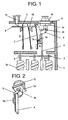
- Fig. 1 illustrates the construction and operation of an essential part in an Embodiment 1 according to the invention
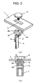
- Fig. 2 show an external view of an assembly structure linking the adjusting dial and the release lever shown in Fig. 1
- Figs. 3 through 8 shows various embodiments of configurations of the adjusting dial and constructions for fastening the adjusting dial to the outer casing.
- members corresponding to those in Fig. 9 are given the same symbols and are not described again.
- Fig. 1 shows an assembly structure of an essential part of a thermally operated overload relay that corresponds to claims 1, 2, and 4 of the invention
- Fig. 2 is a perspective view of an assembled structure linking the adjusting dial and the release lever shown in Fig. 1 ;
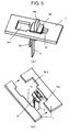
- Figs. 3(a) and 3(b) show a structure for fastening the adjusting dial in any of multiple positions depending on a trigger current value to be set.
- a linkage structure between the release lever 5 and the adjusting dial 11 differs and has the following construction.
- the adjusting link 12 used in the conventional structure of Fig. 9 is omitted, and an end of the release lever 5 is directly coupled to the adjusting dial 11.
- the adjusting dial 11 is composed of a slider 14, a top of which is inserted in a slide groove 1 b formed in the outer casing 1 to movably guide and support the slider.
- the release lever 5 is coupled to the lower end of the slider via a movable shaft 16.
- the slide groove 1b is formed in parallel to the moving direction of the release lever 5.
- the movable shaft 16 can be formed monolithically with the slider 14, which is preferably made of a molded resin.
- a fastening screw (a face screw) 15, simultaneously serving as a handle for adjusting the slider 14, is provided by screwing into a projecting step portion 14a formed at the top of the slider 14.
- the fastening screw 15 screwed from the outside of the outer casing 1 to the slider 14 is fastened to the outer casing 1 at a desired position of the slider 14 that corresponds to the desired trigger current value.
- the fastening screw 15 has a head with a diameter larger than the width of the slide groove 1b to fasten the slider 14 at the outer casing 1 by the fastening screw 15.
- the slider 14 with the fastening screw in an unfastened state is slid to a desired trigger current position referring to a scale on the adjusting dial, and is then fixed at this position by fastening the fastening screw 15.
- the release lever 5 coupled to the slider 14 is positioned and held at the position corresponding to the set trigger current value.
- FIG. 4(a) and 4(b) A variation from the structure of Figs. 3(a) and 3(b) for fastening the slider 14 is shown in Figs. 4(a) and 4(b) .
- the outer casing 1 is shown in Fig. 4(a) as cut out along the slide groove 1b for easy understanding of the fastening structure of the slider 14.
- the cross-section of the top of the slider 14 is like the letter H and is engaged with the edges of slide groove 1b formed in the outer casing 1.
- the tip of the fastening screw 15 that is screwed into the top 14a of the slider is pushed against the surface of the plate of outer casing 1 to fix the slider 14 at a desired position.
- the slide groove 1b has an insertion groove region 1b-1 formed at a longitudinal end portion of the groove.
- the insertion groove region 1b-1 has a greater width than the remaining portion of the groove so that the top 14a of the slider 14 may be inserted to a level where the top 14a with its cross-section shaped like the letter H it can be made to engage the slide groove 1b of the outer casing 1.
- FIGs. 5(a) and 5(b) show another variation from Embodiment 1 corresponding to claim 5 of the invention.
- This Embodiment 2 is provided with a notched latch mechanism in place of the fastening screw 15 in Embodiment 1, thereby fixing the slider 14 of the adjusting dial 11 at a desired position to set a trigger current value.
- the slider 14 has a top 14a with a cross-section of the letter H as in the embodiment of Figs. 4(a) and 4(b) , and the top 14a engages the slide groove 1b in the outer casing 1 and is thus slidably guided and supported.
- the slide groove 1b has a notched teeth row 1c with a serrated surface formed along the longitudinal direction; an engaging spring (latch spring) 17 with a configuration of the letter V composed of a leaf spring is attached to the slider 14 so as to oppose the notched teeth row 1c.
- the reference numeral 14c represents a handle formed on the top of the slider 14. The structure of this embodiment allows adjusting the adjusting dial 11 by sliding the handle 14c without using a fastening screw.
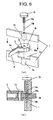
- Figs. 6(a), 6(b) and 7 show an Embodiment 3 corresponding to claims 3 and 6 of the invention.
- the adjusting dial 11 is composed of a disk 18 that is pivotally supported by the outer casing 1 and arranged in a manner that allows rotational operation from outside of the outer casing.
- the release lever 5 is coupled to the disk 18 to position the disk and set a trigger current value.
- a window 1d (a square hole) with a shape of a slit at a place for attaching the adjusting dial, and a bearing portion 1e in the central location of the window 1d and interleaving the window 1d.
- the disk 18 is inserted into the window 1d and a fastening screw 19 serving simultaneously as a support shaft is screwed into the bearing portion 1e and put through a center hole 18a of the disk 18 to rotatably support the disk.
- the release lever 5 is coupled to a movable shaft 16 formed at a peripheral lower portion (inside the outer casing 1) of the disk 18.
- the fastening screw 19 simultaneously serving as a support shaft has a large diameter shaft portion 19a and a small diameter shaft portion 19b formed along the axis thereof.
- a male screw is cut on the large diameter shaft portion 19a;
- a female screw is formed on the internal circumferential surface of the bearing portion 1e of the outer casing 1, the male screw being screwed into the female screw.
- the small diameter shaft portion 19b is put through the center hole 18a of the disk 18 to pivotally support the disk 18.
- a male screw is formed on the small diameter shaft portion 19b of the fastening screw 19 and is screwed into a screw hole formed in the bearing portion 1e to fasten and fix the disk 18 of the adjusting dial.
- the disk 18 is rotated to a desired trigger current position referring to a scale on the adjusting dial, and is then fixed at this position by fastening the screw 19.
- the release lever 5 coupled to the disk 18 is positioned and held at the position corresponding to the trigger current value.
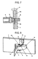
- Fig. 8 shows a variation from Embodiment 3, which is an Embodiment 4 corresponding to claim 7 of the invention.
- This embodiment uses a notched latch mechanism as a means for fastening the disk 18, in place of a fastening screw to fix the disk 18 of the adjusting dial at a trigger current position.
- the disk 18 is pivotally supported on the bearing portion 1e of the outer casing 1 via a support shaft 20.
- the disk 18 has a notched teeth row 18c (actually a notched teeth ring here) with a serrated configuration formed on one end surface of the disk 18 (the upper end surface as viewed in the Fig. 8 ) along the circumferential direction.
- an engaging spring 21 (latch spring) made of a leaf spring is provided on the outer casing 1, and the tip of the engaging spring 21 is engaged with a dent of the notched teeth row 18c to position and latch the disk 18 of the adjusting dial at a desired trigger current position.
Landscapes
- Physics & Mathematics (AREA)
- Thermal Sciences (AREA)
- Breakers (AREA)
Applications Claiming Priority (1)
| Application Number | Priority Date | Filing Date | Title |
|---|---|---|---|
| JP2008032184A JP2009193785A (ja) | 2008-02-13 | 2008-02-13 | 熱動形過負荷継電器 |
Publications (2)
| Publication Number | Publication Date |
|---|---|
| EP2091060A2 true EP2091060A2 (de) | 2009-08-19 |
| EP2091060A3 EP2091060A3 (de) | 2010-03-24 |
Family
ID=40551024
Family Applications (1)
| Application Number | Title | Priority Date | Filing Date |
|---|---|---|---|
| EP08017805A Withdrawn EP2091060A3 (de) | 2008-02-13 | 2008-10-10 | Thermisch betriebenes Überstromrelais |
Country Status (4)
| Country | Link |
|---|---|
| EP (1) | EP2091060A3 (de) |
| JP (1) | JP2009193785A (de) |
| KR (1) | KR20090087799A (de) |
| CN (1) | CN101510487A (de) |
Cited By (1)
| Publication number | Priority date | Publication date | Assignee | Title |
|---|---|---|---|---|
| CN103187213A (zh) * | 2011-12-29 | 2013-07-03 | 上海良信电器股份有限公司 | 热过载继电器的动作机构 |
Families Citing this family (7)
| Publication number | Priority date | Publication date | Assignee | Title |
|---|---|---|---|---|
| CN101916694B (zh) * | 2010-08-17 | 2012-07-11 | 常熟开关制造有限公司(原常熟开关厂) | 断路器的热磁式脱扣器的电流调节装置 |
| CN102723237B (zh) * | 2012-05-10 | 2014-07-09 | 宁波沐趣多电器有限公司 | 一种大电流超温、超压、电磁三合一脱扣保护器 |
| CN103512517A (zh) * | 2012-06-15 | 2014-01-15 | 苏州工业园区高登威科技有限公司 | 热继电器双金属片检测装置 |
| CN103512515A (zh) * | 2012-06-15 | 2014-01-15 | 苏州工业园区高登威科技有限公司 | 热继电器双金属片检测装置 |
| CN104167329B (zh) * | 2013-05-17 | 2018-12-04 | 郭永明 | 高精度热继电器 |
| CN103871778A (zh) * | 2014-03-27 | 2014-06-18 | 福州大学 | 一种记忆合金在过载脱扣器上的应用 |
| CN106710992A (zh) * | 2016-12-02 | 2017-05-24 | 无锡职业技术学院 | 一种新型空气开关 |
Citations (2)
| Publication number | Priority date | Publication date | Assignee | Title |
|---|---|---|---|---|
| JPS5395168U (de) | 1976-12-30 | 1978-08-03 | ||
| JP2005116370A (ja) | 2003-10-08 | 2005-04-28 | Fuji Electric Fa Components & Systems Co Ltd | 熱動形過負荷継電器 |
Family Cites Families (4)
| Publication number | Priority date | Publication date | Assignee | Title |
|---|---|---|---|---|
| JPH0218510Y2 (de) * | 1984-12-06 | 1990-05-23 | ||
| DE3729947A1 (de) * | 1986-09-18 | 1988-04-07 | Mitsubishi Electric Corp | Stromkreisunterbrecher |
| DE10064825A1 (de) * | 2000-12-22 | 2002-07-04 | Abb Patent Gmbh | Justiereinrichtung für den thermischen Auslöser eines Installationsschaltgerätes |
| DE10296638T5 (de) * | 2002-03-28 | 2004-04-22 | Mitsubishi Denki K.K. | Thermisches Überstromrelais |
-
2008
- 2008-02-13 JP JP2008032184A patent/JP2009193785A/ja active Pending
- 2008-09-09 KR KR1020080088680A patent/KR20090087799A/ko not_active Withdrawn
- 2008-10-10 EP EP08017805A patent/EP2091060A3/de not_active Withdrawn
- 2008-10-22 CN CNA200810169143XA patent/CN101510487A/zh active Pending
Patent Citations (2)
| Publication number | Priority date | Publication date | Assignee | Title |
|---|---|---|---|---|
| JPS5395168U (de) | 1976-12-30 | 1978-08-03 | ||
| JP2005116370A (ja) | 2003-10-08 | 2005-04-28 | Fuji Electric Fa Components & Systems Co Ltd | 熱動形過負荷継電器 |
Cited By (2)
| Publication number | Priority date | Publication date | Assignee | Title |
|---|---|---|---|---|
| CN103187213A (zh) * | 2011-12-29 | 2013-07-03 | 上海良信电器股份有限公司 | 热过载继电器的动作机构 |
| CN103187213B (zh) * | 2011-12-29 | 2015-03-25 | 上海良信电器股份有限公司 | 热过载继电器的动作机构 |
Also Published As
| Publication number | Publication date |
|---|---|
| KR20090087799A (ko) | 2009-08-18 |
| CN101510487A (zh) | 2009-08-19 |
| JP2009193785A (ja) | 2009-08-27 |
| EP2091060A3 (de) | 2010-03-24 |
Similar Documents
| Publication | Publication Date | Title |
|---|---|---|
| EP2091060A2 (de) | Thermisch betriebenes Überstromrelais | |
| US5223813A (en) | Circuit breaker rocker actuator switch | |
| JPS5931817B2 (ja) | 遮断器 | |
| KR200491965Y1 (ko) | 회로차단기의 가 조정 열동 트립 기구 | |
| CN108022811B (zh) | 一种具有热脱扣器的断路器 | |
| JP4798243B2 (ja) | 熱動形過負荷継電器 | |
| US8138879B2 (en) | Thermal overload relay | |
| EP0809270A2 (de) | Schaltmechanismus mit reversierendem Federspannungskontakt und thermisches Überlastrelais | |
| JP5003426B2 (ja) | 熱動形過負荷継電器 | |
| EP1672663B1 (de) | Formgedächtnislegierung-auslösemechanismus für einen Erdschluss- oder Lichtbogenfehler-schutzschalter | |
| US6480079B1 (en) | Electrical circuit breaker device | |
| CN108022812B (zh) | 一种具有磁脱扣器的断路器 | |
| EP4576153A1 (de) | Schutzschalter mit gegossenem gehäuse und montageverfahren | |
| KR101789224B1 (ko) | 열동형 과부하 계전기 | |
| US3211862A (en) | Pushbutton-controlled polyphase overload circuit breaker | |
| US6903635B2 (en) | Circuit breaker interface mechanism for auxiliary switch accessory | |
| US8174350B2 (en) | Thermal overload relay | |
| EP2492943B1 (de) | Durch wärme bewegtes überlastrelais | |
| CN101546676A (zh) | 热过载继电器 | |
| JP4419706B2 (ja) | 回路遮断器 | |
| US7106155B2 (en) | Double-lever mechanism, trip actuator assembly and electrical switching apparatus employing the same | |
| JPH0449730B2 (de) | ||
| JP2008300326A (ja) | 熱動形過負荷継電器 | |
| KR20230112703A (ko) | 열동형 과부하 계전기 | |
| US6433659B1 (en) | Cam and axle for adjustable magnetic trip device |
Legal Events
| Date | Code | Title | Description |
|---|---|---|---|
| PUAI | Public reference made under article 153(3) epc to a published international application that has entered the european phase |
Free format text: ORIGINAL CODE: 0009012 |
|
| AK | Designated contracting states |
Kind code of ref document: A2 Designated state(s): AT BE BG CH CY CZ DE DK EE ES FI FR GB GR HR HU IE IS IT LI LT LU LV MC MT NL NO PL PT RO SE SI SK TR |
|
| AX | Request for extension of the european patent |
Extension state: AL BA MK RS |
|
| PUAL | Search report despatched |
Free format text: ORIGINAL CODE: 0009013 |
|
| AK | Designated contracting states |
Kind code of ref document: A3 Designated state(s): AT BE BG CH CY CZ DE DK EE ES FI FR GB GR HR HU IE IS IT LI LT LU LV MC MT NL NO PL PT RO SE SI SK TR |
|
| AX | Request for extension of the european patent |
Extension state: AL BA MK RS |
|
| RIC1 | Information provided on ipc code assigned before grant |
Ipc: H01H 71/74 20060101ALI20100218BHEP Ipc: H01H 71/16 20060101ALI20100218BHEP Ipc: H01H 61/02 20060101ALI20100218BHEP Ipc: H01H 61/01 20060101AFI20090424BHEP |
|
| AKY | No designation fees paid | ||
| STAA | Information on the status of an ep patent application or granted ep patent |
Free format text: STATUS: THE APPLICATION IS DEEMED TO BE WITHDRAWN |
|
| 18D | Application deemed to be withdrawn |
Effective date: 20100925 |
|
| REG | Reference to a national code |
Ref country code: DE Ref legal event code: R108 Effective date: 20110222 Ref country code: DE Ref legal event code: 8566 |