EP4576153A1 - Schutzschalter mit gegossenem gehäuse und montageverfahren - Google Patents
Schutzschalter mit gegossenem gehäuse und montageverfahren Download PDFInfo
- Publication number
- EP4576153A1 EP4576153A1 EP24222594.4A EP24222594A EP4576153A1 EP 4576153 A1 EP4576153 A1 EP 4576153A1 EP 24222594 A EP24222594 A EP 24222594A EP 4576153 A1 EP4576153 A1 EP 4576153A1
- Authority
- EP
- European Patent Office
- Prior art keywords
- bar
- disarming
- adjustment
- circuit breaker
- fixed
- Prior art date
- Legal status (The legal status is an assumption and is not a legal conclusion. Google has not performed a legal analysis and makes no representation as to the accuracy of the status listed.)
- Pending
Links
Images


Classifications
-
- H—ELECTRICITY
- H01—ELECTRIC ELEMENTS
- H01H—ELECTRIC SWITCHES; RELAYS; SELECTORS; EMERGENCY PROTECTIVE DEVICES
- H01H71/00—Details of the protective switches or relays covered by groups H01H73/00 - H01H83/00
- H01H71/74—Means for adjusting the conditions under which the device will function to provide protection
- H01H71/7427—Adjusting only the electrothermal mechanism
- H01H71/7445—Poly-phase adjustment
-
- H—ELECTRICITY
- H01—ELECTRIC ELEMENTS
- H01H—ELECTRIC SWITCHES; RELAYS; SELECTORS; EMERGENCY PROTECTIVE DEVICES
- H01H71/00—Details of the protective switches or relays covered by groups H01H73/00 - H01H83/00
- H01H71/10—Operating or release mechanisms
-
- H—ELECTRICITY
- H01—ELECTRIC ELEMENTS
- H01H—ELECTRIC SWITCHES; RELAYS; SELECTORS; EMERGENCY PROTECTIVE DEVICES
- H01H69/00—Apparatus or processes for the manufacture of emergency protective devices
-
- H—ELECTRICITY
- H01—ELECTRIC ELEMENTS
- H01H—ELECTRIC SWITCHES; RELAYS; SELECTORS; EMERGENCY PROTECTIVE DEVICES
- H01H71/00—Details of the protective switches or relays covered by groups H01H73/00 - H01H83/00
- H01H71/02—Housings; Casings; Bases; Mountings
-
- H—ELECTRICITY
- H01—ELECTRIC ELEMENTS
- H01H—ELECTRIC SWITCHES; RELAYS; SELECTORS; EMERGENCY PROTECTIVE DEVICES
- H01H71/00—Details of the protective switches or relays covered by groups H01H73/00 - H01H83/00
- H01H71/02—Housings; Casings; Bases; Mountings
- H01H71/0207—Mounting or assembling the different parts of the circuit breaker
- H01H71/0214—Housing or casing lateral walls containing guiding grooves or special mounting facilities
-
- H—ELECTRICITY
- H01—ELECTRIC ELEMENTS
- H01H—ELECTRIC SWITCHES; RELAYS; SELECTORS; EMERGENCY PROTECTIVE DEVICES
- H01H9/00—Details of switching devices, not covered by groups H01H1/00 - H01H7/00
- H01H9/20—Interlocking, locking, or latching mechanisms
-
- H—ELECTRICITY
- H01—ELECTRIC ELEMENTS
- H01H—ELECTRIC SWITCHES; RELAYS; SELECTORS; EMERGENCY PROTECTIVE DEVICES
- H01H71/00—Details of the protective switches or relays covered by groups H01H73/00 - H01H83/00
- H01H71/74—Means for adjusting the conditions under which the device will function to provide protection
- H01H71/7427—Adjusting only the electrothermal mechanism
- H01H2071/7454—Adjusting only the electrothermal mechanism with adjustable axis of transmission lever between bimetal element and trip lever
-
- H—ELECTRICITY
- H01—ELECTRIC ELEMENTS
- H01H—ELECTRIC SWITCHES; RELAYS; SELECTORS; EMERGENCY PROTECTIVE DEVICES
- H01H71/00—Details of the protective switches or relays covered by groups H01H73/00 - H01H83/00
- H01H71/74—Means for adjusting the conditions under which the device will function to provide protection
- H01H2071/7481—Means for adjusting the conditions under which the device will function to provide protection with indexing means for magnetic or thermal tripping adjustment knob
-
- H—ELECTRICITY
- H01—ELECTRIC ELEMENTS
- H01H—ELECTRIC SWITCHES; RELAYS; SELECTORS; EMERGENCY PROTECTIVE DEVICES
- H01H83/00—Protective switches, e.g. circuit-breaking switches, or protective relays operated by abnormal electrical conditions otherwise than solely by excess current
- H01H83/02—Protective switches, e.g. circuit-breaking switches, or protective relays operated by abnormal electrical conditions otherwise than solely by excess current operated by earth fault currents
- H01H83/04—Protective switches, e.g. circuit-breaking switches, or protective relays operated by abnormal electrical conditions otherwise than solely by excess current operated by earth fault currents with testing means for indicating the ability of the switch or relay to function properly
-
- H—ELECTRICITY
- H01—ELECTRIC ELEMENTS
- H01H—ELECTRIC SWITCHES; RELAYS; SELECTORS; EMERGENCY PROTECTIVE DEVICES
- H01H83/00—Protective switches, e.g. circuit-breaking switches, or protective relays operated by abnormal electrical conditions otherwise than solely by excess current
- H01H83/20—Protective switches, e.g. circuit-breaking switches, or protective relays operated by abnormal electrical conditions otherwise than solely by excess current operated by excess current as well as by some other abnormal electrical condition
- H01H83/22—Protective switches, e.g. circuit-breaking switches, or protective relays operated by abnormal electrical conditions otherwise than solely by excess current operated by excess current as well as by some other abnormal electrical condition the other condition being imbalance of two or more currents or voltages
- H01H83/223—Protective switches, e.g. circuit-breaking switches, or protective relays operated by abnormal electrical conditions otherwise than solely by excess current operated by excess current as well as by some other abnormal electrical condition the other condition being imbalance of two or more currents or voltages with bimetal elements
Definitions
- the present invention relates to a molded case circuit breaker. More specifically, the present invention relates to a molded case circuit breaker comprising a fixed adjustment disarming bar and an optional variable adjustment disarming bar.
- molded case circuit breakers can have their operation based on thermal, magnetic, thermomagnetic or even electronic principles, through the movement of electrical contacts, and can be used, above all, to protect electrical circuits subject to short circuits and/or electrical overloads generated by electrical current levels that exceed a nominal limit previously established by the connection of input and output terminals, connected to the electrical power supply network to be protected.
- circuit breakers fundamentally work in a similar way to electrical switches, i.e., they work to change the electrical conduction state of an electrical circuit between the "on” (ON) and “off” (OFF) states.
- conventional circuit breakers also include an operating handle that can be operated by a user.
- the temperature of the electrical path operates by being related to a predetermined time delay within a range where the temperature of the electrical path does not exceed the permissible temperature to be regulated, so that the circuit breaker cannot be operated by such a predetermined overcurrent as a limit.
- the determination of the delay in the demonstration characteristic corresponds to the time since the moment in that the overcurrent flows and the bimetal starts to bend before the opening/closing mechanism can be operated by the rotation of an adjustable disarming bar.
- Such delay time is determined by adopting an initial clearance between a bimetal element and a trigger bar and a rotational distance of the disarming bar from a point in time when the bimetal comes into contact with the disarming bar until a point in time when the disarming bar rotates and begins to operate an opening and closing mechanism, having adjustments and calibration of this operating time and defined distances being an important factor so that it activates said electrical contact opening mechanism and promotes electrical interruption.
- molded case thermal-magnetic circuit breakers can be configured to use fixed disarming bars or disarming bars adjustable to the current range.
- circuit breakers with adjustable disarming bars When compared to molded case circuit breakers with adjustable disarming bars, circuit breakers with fixed disarming bars have a simpler construction, since they do not require additional parts to adjust the current range.
- molded case circuit breakers with adjustable bars have a construction that is similar to that of circuit breakers with fixed disarming bar adjustment and thermal disarming, so it would be desirable for the more economical construction of fixed adjustment circuit breakers to be used as a basis for the manufacture of circuit breakers with adjustable disarming bars, without major conceptual modifications.
- a trigger mechanism of a circuit breaker capable of adjusting a trigger time interval, including a bimetal element, a guide cap that is provided to the bimetal and a hole, a hollow hole-shaped guide rod connected to the hole in the guide cap; a control bar that has a partially protruding structure being connected by penetration into the hollow hole in the guide rod; and an adjustable disarming bar that is spaced from the control bar, being capable of being in contact with the control bar by an operation of the bimetal element.
- the patent teaches an inclined cross-section in a part facing the control rod, which can cause a different distance and consequently, different delay times of the tripping of the interrupting device.
- Patent CN214068673U describes a molded case circuit breaker with thermally adjustable device.
- the adjustable device includes an adjusting rod movably arranged on the pull rod and combined with a bimetallic strip of a thermal magnetic trigger and a combined adjusting knob, which is rotatably arranged on the upper cover corresponding to the adjusting rod, and wherein the upper end of said adjusting knob is provided with an adjusting groove exposed outside the upper cover, the lower end of the adjusting knob is provided with a lever portion combined with the adjusting rod, and the adjusting lever is provided with a limit groove combined with the lever portion inserted into the limit groove and constitutes the connection between the adjusting knob and the adjusting rod, and in that the adjusting rod moves with the adjusting knob and can abut against the bimetallic plate.
- transverse bar assembly comprises an assembly of a transverse bar and a snap bar engaged by said transverse bar.
- the transverse bar and the snap bar are rotatably coupled so as to be rotatable about the same axis.
- This transverse adjustment bar has adjustable parts such as screws in contact with bimetals on inclined adjustment surfaces.
- patent KR10-2275002B1 is known for a thermally adjustable trigger mechanism of a molded case circuit breaker that includes a bimetal, a contact element formed on one side of the bimetal and an adjustable trigger bar that is operated when the bimetal is deformed to push the contact element into a state where the contact member is separated from the bimetal.
- the adjustable trigger bar comprises a contact surface that has planes with different heights (inclined plane) towards the contact member in a position of touching and separating the contact member.
- the device is assembled in two parts by protrusions of a movable bar in insertion spaces through slight deformation. This adjustment bar only operates after assembly between parts that are intended to be assembled in a plane perpendicular to the adjustment units, such as screws, and the end result is a variable adjustment bar.
- a molded case circuit breaker having a circuit breaker base and at least one circuit breaker cover, comprising:
- the circuit breaker cover comprises, on its internal surface, seats, where at least one surface edge of said fixed disarming bar or said variable adjustment disarming bar can be accommodated in a rotatable manner.
- Said circuit breaker could be constructed, as already known in the state of the art, having an intermediate casing, or additional cover, without prejudice to the present invention.
- the present invention also consists in the fact that a central concave surface comprises a central horizontal portion of said variable adjustment disarming bar, which overlaps said inclined portion, projecting towards the plurality of bimetals, said central horizontal portion in the shape of a "U” having a recess, which defines said horizontal portion, where a current adjustment dial is arranged vertically.
- said current adjustment dial comprises a vertical eccentric bar which is guided by the recess surface of said central horizontal portion, and can modify the adjustment position of the variable adjustment disarming bar.
- the distance between the transverse distance adjustment elements and the concave surfaces is changed by actuating the current adjustment dial, in one example, preferably positioned in the central position of a 3-pole interrupting circuit breaker. This occurs through transverse distance adjustment elements, such as adjustment screws, which touch said inclined portion of said variable adjustment disarming bar, which moves laterally, by the action of turning a vertical eccentric bar of said current adjustment dial, guided by said recess of said horizontal portion, preferably in a "U" shape.
- the present invention further comprises a circuit test button, said circuit test button comprising a first drive bar physically associated with the fixed disarming bar and a second drive bar physically associated with the variable adjustment disarming bar, wherein said circuit test button is disposed behind said fixed disarming bar relative to said distance adjustment transverse elements.
- the circuit breaker cover comprises a hole where the circuit test button is disposed.
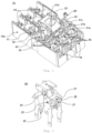
- the present invention describes a preferred embodiment of a molded case circuit breaker (10), comprising a circuit breaker base (10a).
- said circuit breaker is presented without a top cover (10b) (partially seen in its internal portion in Figure 4 ).
- said circuit breaker (10) comprises an operating mechanism (20), which acts in the event of a short-circuit or overcurrent fault.
- Said fixed adjustment disarming bar (30) is installed and operates in a rotatable manner, to control a trigger function, synchronously or not, opening at least one movable contact (41a) in relation to at least one fixed contact (41b) (seen in Figure 18 ), between the power supply terminals (43) and the load terminals (44), associated with a system of rotary contacts (42), associated with at least one bimetal (40), in at least one of the poles of said circuit breaker (10), in the aforementioned occurrence of a fault in the electrical circuit associated therewith.
- the person skilled in the art is commonly aware that the power terminals (43) or the load terminals (44) can be coupled alternately in their functions.
- said fixed adjustment disarming bar (30) (best seen in Figure 6 ) comprises at least one flat contact surface (31a, 31b, 31c), wherein when additionally provided with at least one lateral flat contact surface (31a, 31c) and a central flat contact surface (31b) project vertically from an upper surface (32) of said fixed disarming bar (30).
- the bimetal (40) sensitive to changes in current resulting from said faults in at least one of the poles of said circuit breaker (10), comprises in its upper portion at least one distance adjustment transverse element (50), wherein at least one bimetal (40) is arranged frontally and parallel to at least one flat contact surface (31a, 31b, 31c).
- the distance between at least one distance adjustment transverse element (50) and the fixed adjustment disarming bar (30) should preferably be constant during operation of the circuit breaker (10), comprising a fixed adjustment.
- the calibration adjustment in this case, is made in a factory environment, with no possibility of subsequent modification without disassembling said circuit breaker (10).
- at least one of at least one bimetal (40) of said at least one pole is deformed, connected to at least one distance adjustment transverse element (50), which can then reach and touch at least one of the flat contact surfaces (31a, 31b, 31c) of the fixed adjustment disarming bar (30), which can rotate.
- said circuit breaker (10) additionally comprises the mounting of a variable adjustment disarming bar (60) (best seen in Figure 7 ) disposed upon said fixed adjustment disarming bar (30) and extending along the length of said fixed disarming bar (30), wherein said variable adjustment disarming bar (60) contains at least one concave surface (61a, 61b and 61c) (best seen in Figures 7 , 8b, 9b and 10b ).
- Said concave surfaces (61a, 61b, 61c), when assembled upon said fixed disarming bar (30), are disposed, respectively, on an edge (33), adjacently so that the flat surfaces (31a, 31b, 31c) surround said edge (33), ensuring a positioning of said variable adjustment disarming bar (60) upon said fixed disarming bar (30).
- At least one concave surface (61a, 61b, 61c) of said variable adjustment bar (60) comprises an inclined portion (62) that projects toward the upper portion of at least one bimetal (40).
- Said central concave surface (61b) further comprises a horizontal portion (63) above said inclined portion (62) that projects toward at least one said bimetal (40), said horizontal portion (63) having a recess (64) wherein a current adjustment dial (70) is disposed.
- Said current adjustment dial (70) comprises an eccentric bar (71) that can move laterally the position of said variable adjustment bar (60) relative to the fixed disarming bar (30) by contacting said recess surface (64) (best seen in Figure 14 ).
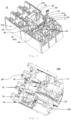
- said circuit breaker cover (10b) of said circuit breaker (10) on its internal surface comprises seats (12), where a central curved surface (61d) of said variable adjustment disarming bar accommodates in a rotatable manner, when assembled in an additive manner, in addition to a support face (13) for a stroke limiter (31e) of said fixed disarming bar (30) (better seen in Figure 6 ), and a hole (83) for passing the test button (80) (seen in Figure 5 ).
- Said circuit breaker top cover (10b) of said circuit breaker (10) also has internal side walls (14) and a through hole (15), for the passage of eccentric bar (71) of current adjustment dial (70) (seen in Figure 3 ).
- the current adjustment dial (70) by means of the eccentric bar (71), has the function of changing the distance between the distance adjustment transverse elements (50) in relation to at least one inclined portion (62).
- the variable adjustment disarming bar (60) moves laterally on the fixed disarming bar (30) (better observed in Figure 7 ), which can be closer or further away from said distance adjustment transverse elements (50), increasing or reducing a gap between them.
- said circuit breaker (10) comprises a circuit test button (80), said circuit test button (80) comprising a drive bar (81), physically associated with said fixed disarming bar (30), and a spring-loaded return bar (82), physically associated with a seat (not shown) of the inner surface of said cover (10b).
- Said circuit test button (80) is disposed in a hole (83) provided in the circuit breaker cover (10b) (seen in Figure 4 ), so that said circuit test button (80) is positioned above said fixed disarming bar (30).
- said circuit test button (80) can perform a triggering test when actuated, causing the fixed adjustment disarming bar (30) fixed and bearing via at least one support (26), or the variable adjustment disarming bar (60) (if this is additively mounted), are rotated and, consequently, said support (26) moves the trigger (23) of the operating mechanism (20), interrupting the associated electrical circuit, through said rotary contact system (42).
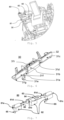
- Figure 6 shows, in a preferred embodiment of the present invention, a top perspective view of at least one lateral flat contact surface (31a, 31c) and of the central flat contact surface (31b), which projects vertically from an upper surface (32). Additionally, it shows a limit wall (31f) of the fixed adjustment disarming bar (30), projecting above and below said upper surface (32) of said fixed disarming bar (30), in addition to a lower surface (31g), contained in said flat contact surfaces (31a, 31b, 31c) and a rotary stroke limiter arm (31e).
- a hole (31i) is also provided, used for the passage of a fastener (31j) (seen in Figure 13 ), to fix said fixed disarming bar (30) in the hole (27) of the operating mechanism (20), (seen in Figure 2 ) of said circuit breaker (10).
- Figure 7 shows, in a preferred embodiment of the present invention, a top perspective view of the variable adjustment disarming bar (60), at least one central curved surface (61d), at least one concave seating surface (61a, 61b, 61c) (also seen in Figures 8b, 9b, 10b ), at least one inclined portion (62), and also said preferably horizontal portion (63), comprising a recess (64) for receiving of an said eccentric bar (71) (seen in Figure 3 ), positioned above said inclined portion (62), which projects towards at least one bimetal (40) (seen in Figure 3 ), and lock latch (65).
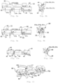
- Figure 8a shows a front view of the variable adjustment disarming bar (60) in a first vertical assembly seating preparation position, on the upper part of the fixed adjustment disarming bar (30), where at least one latch (65) is seen, so that it can slide vertically in at least one free space (34) until at least one concave surface (61a, 61b and 61c) (seen in Figures 7 and 8b ) can touch an upper edge (33) of said fixed adjustment disarming bar (30), of at least one flat contact surface (31a, 31b, 31c), in a preferred embodiment of the present invention.
- Figure 8b is a side view of the variable adjustment disarming bar (60) in a first vertical mounting position from the top of the fixed adjustment disarming bar (30). In this first position there can also be seen a said concave surface (61a, 61b, 61c) aligned vertically with said edge (33) of at least one said flat contact surface (31a, 31b, 31c), in a preferred embodiment of the present invention.
- Figure 9a shows a front view of the variable adjustment disarming bar (60) in a second mounting seating position on top of the fixed adjustment disarming bar (30), where at least one latch (65) is seen, positioned vertically aligned with at least one free space (34) of said fixed adjustment disarming bar (30) where the concave surface (61a, 61b and 61c) (seen in Figure 8b ) can touch an upper edge (33) of at least one flat contact surface (31a, 31b, 31c) of said fixed adjustment disarming bar (30) (also seen in Figure 9b ).
- said latch (65) can also be seen in side view in vertical locking preparation position (seen in Figures 9a , in a preferred embodiment of the present invention.
- Figure 10a shows a front view of the variable adjustment disarming bar (60) in a final mounting seating position on top of the fixed adjustment disarming bar (30), where at least one latch (65) is seen, in horizontal lateral displacement after the second preparatory mounting position, so that it can vertically prevent a removal of the variable adjustment disarming bar (60) from said fixed adjustment disarming bar (30) (also seen in Figure 10b ) .
- said vertical latch (65) can be seen in Figures 10a and 10b together with at least one concave surface (61a, 61b and 61c), involving at least one edge (33) and which engages at least one lower surface (31g), having in between at least one flat contact surface (31a, 31b, 31c), in addition to a lateral limit (66) (seen in Figure 7 ), which can touch the limit wall (31f) (seen in Figure 6 ) of said fixed adjustment disarming bar (30), in a preferred embodiment of the present invention.
- Figure 11 shows a bottom perspective view of the variable adjustment disarming bar (60) mounted in the final operating position next to the fixed adjustment disarming bar (30), and where at least one upper edge (33) and at least one lower surface (31g) of said fixed adjustment disarming bar (30) can be seen being surrounded by at least one concave surface (61a, 61b, 61c) (best seen in figure 7 ), and at least one latch (65).
- Figure 12 shows a top perspective view of the variable adjustment disarming bar (60) mounted in the final operating position next to the fixed adjustment disarming bar (30), in which it can be seen that said variable adjustment disarming bar (60) can slide laterally over said fixed adjustment disarming bar (30) according to the action of the adjustment of said distance adjustment transverse element (50), capable of modifying a triggering response time of a thermomagnetic set (not shown) and at least one bimetal (40) in contact and which results in a disengagement of said operating mechanism (20), opening a movable contact (41a) in relation to at least one fixed contact (41b) of a rotary contact system (42) of said circuit breaker (10), according to a current circulating in the electrical circuit, which said circuit breaker (10) protects and monitors.
- This assembly system is completed after the cover (10b) of said circuit breaker (10) has been assembled, which limits said sliding lateral displacement of the variable disarming bar (60) upon said fixed adjustment disarming bar (30), through internal side walls (14) of said cover (10b), increasing or reducing the spacing of at least one inclined portion (62) in relation to distance adjustment transverse elements (50) of at least one bimetal (40), capable of effecting a trigger disarm and interrupting a circulating current in the circuit that said circuit breaker (10) protects and monitors.
- said latching (65) (seen in Figure 7 ) is not capable of aligning with said at least one free space (34), due to the presence of said cover (10b) and prevents a disassembly between them, until said cover (10b) is removed.
- Figure 13 shows in a top view the fixed disarming bar (30) mounted on the operating mechanism (20) by means of the fastener (31j), which passes through the hole (31i) (seen in Figure 6 ) of said fixed disarming bar (30) and reaches the hole (27) of said operating mechanism (20). It is possible to observe the flat contact surface (31a, 31b, 31c) projecting vertically and frontally to at least one distance adjustment transverse element (50), allowing a fixed distance adjustment only on the inside of the circuit breaker (10).
- the inclined portion (62) of the variable disarming bar (60) is projected vertically with respect to a current adjustment dial (70) and frontally inclined with respect to at least one distance adjustment transverse element (50), allowing a variable adjustment of a distance between them.
- the adjustment can be carried out through said current adjustment dial (70) (seen in Figures 3 , 14 , 15 and 16 ), arranged through a through hole (15) in the upper outer part of the cover (10b), so that a desired thermal nominal value for the operation of the circuit breaker (10) is set.
- Figure 14 shows an illustrative example of an initial adjustment embodiment of the current adjustment dial (70), in a top view, where the variable disarming bar (60) variable disarming bar (60) is mounted on the fixed adjustment disarming bar (30) (seen in Figure 6 ) in a final vertical mounting seating position (seen in Figures 10a and 10b ). Said fixed disarming bar (30) and said variable disarming bar (60) meet with their left faces aligned (67a), resulting in an initial thermal graduation of operation of the circuit breaker (10).
- Figure 15 shows an illustrative example of an adjustment embodiment, in a top view, comprising the variable disarming bar (60) mounted on the fixed adjustment disarming bar (30) (seen in Figure 6 ), in a final vertical mounting position (seen in Figures 10a and 10b ).
- An intermediate adjustment of the graduation of the current adjustment dial (70) can be seen, with the inclined portion (62) projecting vertically and frontally inclined in relation to at least one distance adjustment transverse element (50), where said fixed disarming bar (30) and said variable disarming bar (60) in this position meet with the left faces presenting an intermediate displacement (67b), and as a consequence said distance adjustment transverse element (50) approaches said inclined portion (62), resulting in said intermediate thermal graduation of operation of said circuit breaker (10).
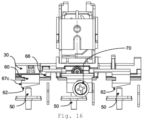
- Figure 16 shows an illustrative example of maximum final adjustment embodiment, in a top view comprising the variable disarming bar (60) mounted on the fixed adjustment disarming bar (30) (seen in Figure 6 ), in a final vertical assembly seating position (seen in Figures 10a and 10b ).
- a maximum final adjustment of the current adjustment dial (70) can be seen, having the inclined portion (62) projected vertically and frontally inclined in relation to the at least one distance adjustment transverse element (50), where said fixed adjustment bar (30) and said variable adjustment bar (60) meet with the left faces presenting a maximum final displacement (67c), limited by said lateral limit (66) of said variable adjustment bar (60) (best seen in Figure 7 ), and as a consequence the distance adjustment transverse element (50) approaches even more to said inclined portion (62), being able to reach a maximum final thermal graduation of operation of the circuit breaker (10).
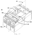
- FIG 17 shows a top perspective view of the assembled circuit breaker (10), object of the present invention, comprising a circuit breaker base (10a), a circuit breaker cover (10b), a manual operating handle (22), a current adjustment dial (70) for adjusting a trigger function in a variable thermal operating range, associated with the fixed disarming bar (30) or the variable adjustment disarming bar (60) (best seen in Figures 6 to 16 ), in addition to the indication of a cross-section in the "XY" plane, shown in Figure 18 of the circuit breaker (10).
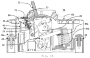
- Figure 18 shows a longitudinal sectional view in the "XY" plane, shown in Figure 17 , of said circuit breaker (10), comprising a fixed adjustment disarming bar (30), arranged in a movable and rotatable manner, on the bar (21) of the operating mechanism (20) and associated with the operating movement of a handle (22) of the circuit breaker (10), capable of switching said circuit breaker (10) on or off, manually.
- a fixed adjustment disarming bar (30) arranged in a movable and rotatable manner, on the bar (21) of the operating mechanism (20) and associated with the operating movement of a handle (22) of the circuit breaker (10), capable of switching said circuit breaker (10) on or off, manually.
- variable disarming bar (60) is installed on the edge (33) of the fixed adjustment disarming bar (30) (illustrated in Figures 8a to 12 ), so as to perform a trigger function at a variable thermal operating gradation, synchronously or not, opening at least one moving contact (41a) in relation to at least one fixed contact (41b) between the power supply terminals (43) and the load terminals (44), associated with a system of rotating contacts (42), associated with at least one bimetal (40), in at least one of the current path poles of said circuit breaker (10), in the aforementioned occurrence of typical short-circuit or overcurrent faults.
- the bimetals could be provided with an inclined surface on the upper part, facing the distance adjustment elements (such as screws), fixed on the variable adjustment bar. This solution would be obvious and should be considered within the scope of the present invention.
Landscapes
- Engineering & Computer Science (AREA)
- Manufacturing & Machinery (AREA)
- Breakers (AREA)
Applications Claiming Priority (1)
| Application Number | Priority Date | Filing Date | Title |
|---|---|---|---|
| BR102023027243-6A BR102023027243A2 (pt) | 2023-12-22 | Disjuntor em caixa moldada e método de montagem |
Publications (1)
| Publication Number | Publication Date |
|---|---|
| EP4576153A1 true EP4576153A1 (de) | 2025-06-25 |
Family
ID=94116864
Family Applications (1)
| Application Number | Title | Priority Date | Filing Date |
|---|---|---|---|
| EP24222594.4A Pending EP4576153A1 (de) | 2023-12-22 | 2024-12-20 | Schutzschalter mit gegossenem gehäuse und montageverfahren |
Country Status (2)
| Country | Link |
|---|---|
| EP (1) | EP4576153A1 (de) |
| CN (1) | CN120199655A (de) |
Cited By (1)
| Publication number | Priority date | Publication date | Assignee | Title |
|---|---|---|---|---|
| CN121171850A (zh) * | 2025-11-18 | 2025-12-19 | 宁波奇乐电气集团有限公司 | 一种多断点触头系统组合式断路器 |
Citations (5)
| Publication number | Priority date | Publication date | Assignee | Title |
|---|---|---|---|---|
| KR20150111473A (ko) | 2014-03-25 | 2015-10-06 | 현대중공업 주식회사 | 트립 갭 조정이 가능한 회로차단기의 트립 장치 |
| EP3242314B1 (de) * | 2016-05-04 | 2019-03-06 | LSIS Co., Ltd. | Einstellbarer thermischer auslösungsmechanismus für schutzschalter |
| KR102271519B1 (ko) | 2019-11-18 | 2021-07-01 | 엘에스일렉트릭(주) | 크로스바 조립체 및 이를 포함하는 트립 장치 |
| KR102275002B1 (ko) | 2019-11-12 | 2021-07-08 | 엘에스일렉트릭(주) | 트립 장치 |
| CN214068673U (zh) | 2021-01-26 | 2021-08-27 | 环宇高科有限公司 | 一种带热可调装置的塑壳断路器 |
-
2024
- 2024-12-20 EP EP24222594.4A patent/EP4576153A1/de active Pending
- 2024-12-20 CN CN202411887776.XA patent/CN120199655A/zh active Pending
Patent Citations (5)
| Publication number | Priority date | Publication date | Assignee | Title |
|---|---|---|---|---|
| KR20150111473A (ko) | 2014-03-25 | 2015-10-06 | 현대중공업 주식회사 | 트립 갭 조정이 가능한 회로차단기의 트립 장치 |
| EP3242314B1 (de) * | 2016-05-04 | 2019-03-06 | LSIS Co., Ltd. | Einstellbarer thermischer auslösungsmechanismus für schutzschalter |
| KR102275002B1 (ko) | 2019-11-12 | 2021-07-08 | 엘에스일렉트릭(주) | 트립 장치 |
| KR102271519B1 (ko) | 2019-11-18 | 2021-07-01 | 엘에스일렉트릭(주) | 크로스바 조립체 및 이를 포함하는 트립 장치 |
| CN214068673U (zh) | 2021-01-26 | 2021-08-27 | 环宇高科有限公司 | 一种带热可调装置的塑壳断路器 |
Cited By (1)
| Publication number | Priority date | Publication date | Assignee | Title |
|---|---|---|---|---|
| CN121171850A (zh) * | 2025-11-18 | 2025-12-19 | 宁波奇乐电气集团有限公司 | 一种多断点触头系统组合式断路器 |
Also Published As
| Publication number | Publication date |
|---|---|
| CN120199655A (zh) | 2025-06-24 |
Similar Documents
| Publication | Publication Date | Title |
|---|---|---|
| US5467069A (en) | Device for adjusting the tripping threshold of a multipole circuit breaker | |
| US5466903A (en) | Current limiting circuit breaker | |
| EP0434338B1 (de) | Ausschalter mit Zustandsanzeigehilfsschalter | |
| US4931757A (en) | Contactor and/or circuit breaker | |
| EP4576153A1 (de) | Schutzschalter mit gegossenem gehäuse und montageverfahren | |
| US5416291A (en) | Current limiting circuit breaker operating mechanism including linkage | |
| KR200491965Y1 (ko) | 회로차단기의 가 조정 열동 트립 기구 | |
| NZ220481A (en) | Circuit breaker thermal overload rating adjusted by trip bar movement | |
| JPH0828180B2 (ja) | 回路遮断器 | |
| US6255925B1 (en) | Thermal-magnetic trip unit with adjustable magnetic tripping | |
| US6747534B1 (en) | Circuit breaker with dial indicator for magnetic trip level adjustment | |
| EP2091060A2 (de) | Thermisch betriebenes Überstromrelais | |
| US3288965A (en) | Multiple circuit breaker assembly with common tripping | |
| US4510479A (en) | PC-board mounted thermal breaker | |
| EP2133899A2 (de) | Elektrische Schaltvorrichtung und Auslösungsdrückeranordnung dafür | |
| US6853274B2 (en) | Circuit breaker | |
| US5909161A (en) | Intermediate latch for a molded case circuit breaker | |
| US3293577A (en) | Undervoltage release for circuit breaker | |
| CN108022812B (zh) | 一种具有磁脱扣器的断路器 | |
| CN103262199B (zh) | 闭锁装置以及具有该闭锁装置的操作机构 | |
| US3240904A (en) | Circuit breaker assembly | |
| BR102023027243A2 (pt) | Disjuntor em caixa moldada e método de montagem | |
| EP0556602B1 (de) | Thermischer Auslöser für elektrische Schaltgeräte | |
| EP1126489B1 (de) | Verbesserte Auslösewellenanordnung für einen Schutzschalter mit kleinerem Innenraum | |
| US3103565A (en) | walker etal |
Legal Events
| Date | Code | Title | Description |
|---|---|---|---|
| PUAI | Public reference made under article 153(3) epc to a published international application that has entered the european phase |
Free format text: ORIGINAL CODE: 0009012 |
|
| STAA | Information on the status of an ep patent application or granted ep patent |
Free format text: STATUS: THE APPLICATION HAS BEEN PUBLISHED |
|
| AK | Designated contracting states |
Kind code of ref document: A1 Designated state(s): AL AT BE BG CH CY CZ DE DK EE ES FI FR GB GR HR HU IE IS IT LI LT LU LV MC ME MK MT NL NO PL PT RO RS SE SI SK SM TR |
|
| STAA | Information on the status of an ep patent application or granted ep patent |
Free format text: STATUS: REQUEST FOR EXAMINATION WAS MADE |
|
| 17P | Request for examination filed |
Effective date: 20251223 |
|
| GRAP | Despatch of communication of intention to grant a patent |
Free format text: ORIGINAL CODE: EPIDOSNIGR1 |
|
| STAA | Information on the status of an ep patent application or granted ep patent |
Free format text: STATUS: GRANT OF PATENT IS INTENDED |