EP2492002A1 - Behandlungsvorrichtung zur dispersion, auflösung, kompatibilisierung oder emulgierung von gas/flüssigkeit oder flüssigkeit/flüssigkeit - Google Patents
Behandlungsvorrichtung zur dispersion, auflösung, kompatibilisierung oder emulgierung von gas/flüssigkeit oder flüssigkeit/flüssigkeit Download PDFInfo
- Publication number
- EP2492002A1 EP2492002A1 EP10825064A EP10825064A EP2492002A1 EP 2492002 A1 EP2492002 A1 EP 2492002A1 EP 10825064 A EP10825064 A EP 10825064A EP 10825064 A EP10825064 A EP 10825064A EP 2492002 A1 EP2492002 A1 EP 2492002A1
- Authority
- EP
- European Patent Office
- Prior art keywords
- liquid
- pressurizing
- gas
- centrifugal pump
- fluid
- Prior art date
- Legal status (The legal status is an assumption and is not a legal conclusion. Google has not performed a legal analysis and makes no representation as to the accuracy of the status listed.)
- Withdrawn
Links
- 239000007788 liquid Substances 0.000 title claims abstract description 118
- 239000012530 fluid Substances 0.000 claims abstract description 79
- 238000004945 emulsification Methods 0.000 claims abstract description 40
- 238000012545 processing Methods 0.000 claims abstract description 37
- 238000004090 dissolution Methods 0.000 claims abstract description 28
- 238000005063 solubilization Methods 0.000 claims abstract description 27
- 230000007928 solubilization Effects 0.000 claims abstract description 27
- 239000006185 dispersion Substances 0.000 claims abstract description 25
- 238000000638 solvent extraction Methods 0.000 claims description 14
- 239000007789 gas Substances 0.000 description 73
- XLYOFNOQVPJJNP-UHFFFAOYSA-N water Substances O XLYOFNOQVPJJNP-UHFFFAOYSA-N 0.000 description 57
- UFHFLCQGNIYNRP-UHFFFAOYSA-N Hydrogen Chemical compound [H][H] UFHFLCQGNIYNRP-UHFFFAOYSA-N 0.000 description 30
- 238000000034 method Methods 0.000 description 30
- 238000004519 manufacturing process Methods 0.000 description 29
- 239000001257 hydrogen Substances 0.000 description 24
- 229910052739 hydrogen Inorganic materials 0.000 description 24
- 238000003860 storage Methods 0.000 description 18
- 238000003756 stirring Methods 0.000 description 16
- 230000001965 increasing effect Effects 0.000 description 12
- 230000008569 process Effects 0.000 description 12
- 238000007906 compression Methods 0.000 description 11
- 230000006835 compression Effects 0.000 description 11
- 238000002156 mixing Methods 0.000 description 10
- 239000003921 oil Substances 0.000 description 10
- 230000003068 static effect Effects 0.000 description 10
- 239000000839 emulsion Substances 0.000 description 9
- 230000009471 action Effects 0.000 description 8
- 238000007599 discharging Methods 0.000 description 8
- 238000010494 dissociation reaction Methods 0.000 description 8
- 230000005593 dissociations Effects 0.000 description 8
- QVGXLLKOCUKJST-UHFFFAOYSA-N atomic oxygen Chemical compound [O] QVGXLLKOCUKJST-UHFFFAOYSA-N 0.000 description 7
- 239000003814 drug Substances 0.000 description 7
- 229940079593 drug Drugs 0.000 description 7
- 239000001301 oxygen Substances 0.000 description 7
- 229910052760 oxygen Inorganic materials 0.000 description 7
- 239000007787 solid Substances 0.000 description 7
- MYMOFIZGZYHOMD-UHFFFAOYSA-N Dioxygen Chemical compound O=O MYMOFIZGZYHOMD-UHFFFAOYSA-N 0.000 description 6
- 229910001882 dioxygen Inorganic materials 0.000 description 6
- 230000033116 oxidation-reduction process Effects 0.000 description 6
- 238000005119 centrifugation Methods 0.000 description 5
- 230000005587 bubbling Effects 0.000 description 4
- 230000008859 change Effects 0.000 description 4
- 230000001276 controlling effect Effects 0.000 description 4
- 230000003247 decreasing effect Effects 0.000 description 4
- 230000001804 emulsifying effect Effects 0.000 description 4
- 230000007613 environmental effect Effects 0.000 description 4
- 235000013305 food Nutrition 0.000 description 4
- 239000000499 gel Substances 0.000 description 4
- 150000002431 hydrogen Chemical class 0.000 description 4
- 239000000463 material Substances 0.000 description 4
- 239000000203 mixture Substances 0.000 description 4
- 230000009467 reduction Effects 0.000 description 4
- 230000003381 solubilizing effect Effects 0.000 description 4
- 239000002537 cosmetic Substances 0.000 description 3
- 239000006071 cream Substances 0.000 description 3
- 239000010432 diamond Substances 0.000 description 3
- 230000000694 effects Effects 0.000 description 3
- 238000002474 experimental method Methods 0.000 description 3
- 239000006260 foam Substances 0.000 description 3
- 235000020124 milk-based beverage Nutrition 0.000 description 3
- 239000000243 solution Substances 0.000 description 3
- CBENFWSGALASAD-UHFFFAOYSA-N Ozone Chemical compound [O-][O+]=O CBENFWSGALASAD-UHFFFAOYSA-N 0.000 description 2
- 230000003078 antioxidant effect Effects 0.000 description 2
- 235000013361 beverage Nutrition 0.000 description 2
- 230000002708 enhancing effect Effects 0.000 description 2
- 239000000446 fuel Substances 0.000 description 2
- 239000000295 fuel oil Substances 0.000 description 2
- GPRLSGONYQIRFK-UHFFFAOYSA-N hydron Chemical compound [H+] GPRLSGONYQIRFK-UHFFFAOYSA-N 0.000 description 2
- 235000015110 jellies Nutrition 0.000 description 2
- 239000008274 jelly Substances 0.000 description 2
- 230000002093 peripheral effect Effects 0.000 description 2
- 238000005086 pumping Methods 0.000 description 2
- 235000021419 vinegar Nutrition 0.000 description 2
- 239000000052 vinegar Substances 0.000 description 2
- JZUFKLXOESDKRF-UHFFFAOYSA-N Chlorothiazide Chemical compound C1=C(Cl)C(S(=O)(=O)N)=CC2=C1NCNS2(=O)=O JZUFKLXOESDKRF-UHFFFAOYSA-N 0.000 description 1
- 238000005299 abrasion Methods 0.000 description 1
- 230000004913 activation Effects 0.000 description 1
- 239000000443 aerosol Substances 0.000 description 1
- 239000003570 air Substances 0.000 description 1
- 230000000844 anti-bacterial effect Effects 0.000 description 1
- 239000003963 antioxidant agent Substances 0.000 description 1
- 238000013459 approach Methods 0.000 description 1
- 125000003118 aryl group Chemical group 0.000 description 1
- 230000006399 behavior Effects 0.000 description 1
- 235000014121 butter Nutrition 0.000 description 1
- 239000000470 constituent Substances 0.000 description 1
- 230000002596 correlated effect Effects 0.000 description 1
- 238000010168 coupling process Methods 0.000 description 1
- 238000005859 coupling reaction Methods 0.000 description 1
- 229910003460 diamond Inorganic materials 0.000 description 1
- 239000012153 distilled water Substances 0.000 description 1
- 238000009826 distribution Methods 0.000 description 1
- 235000015071 dressings Nutrition 0.000 description 1
- 239000003651 drinking water Substances 0.000 description 1
- 235000020188 drinking water Nutrition 0.000 description 1
- 238000005868 electrolysis reaction Methods 0.000 description 1
- 238000005187 foaming Methods 0.000 description 1
- 235000011389 fruit/vegetable juice Nutrition 0.000 description 1
- 229940038487 grape extract Drugs 0.000 description 1
- XLYOFNOQVPJJNP-ZSJDYOACSA-N heavy water Substances [2H]O[2H] XLYOFNOQVPJJNP-ZSJDYOACSA-N 0.000 description 1
- 235000020603 homogenised milk Nutrition 0.000 description 1
- 235000015243 ice cream Nutrition 0.000 description 1
- 239000003978 infusion fluid Substances 0.000 description 1
- 229910052500 inorganic mineral Inorganic materials 0.000 description 1
- 238000004898 kneading Methods 0.000 description 1
- 239000008268 mayonnaise Substances 0.000 description 1
- 235000010746 mayonnaise Nutrition 0.000 description 1
- 229910052751 metal Inorganic materials 0.000 description 1
- 239000002184 metal Substances 0.000 description 1
- 150000002739 metals Chemical class 0.000 description 1
- 239000000693 micelle Substances 0.000 description 1
- 235000013336 milk Nutrition 0.000 description 1
- 239000008267 milk Substances 0.000 description 1
- 210000004080 milk Anatomy 0.000 description 1
- 239000011707 mineral Substances 0.000 description 1
- 125000004430 oxygen atom Chemical group O* 0.000 description 1
- 238000005191 phase separation Methods 0.000 description 1
- 229920002338 polyhydroxyethylmethacrylate Polymers 0.000 description 1
- 230000004044 response Effects 0.000 description 1
- 239000002904 solvent Substances 0.000 description 1
- -1 sport drink Substances 0.000 description 1
- 238000005507 spraying Methods 0.000 description 1
- 230000001954 sterilising effect Effects 0.000 description 1
- 238000004659 sterilization and disinfection Methods 0.000 description 1
- 239000000126 substance Substances 0.000 description 1
- 238000011144 upstream manufacturing Methods 0.000 description 1
- 235000013618 yogurt Nutrition 0.000 description 1
Images


Classifications
-
- A—HUMAN NECESSITIES
- A23—FOODS OR FOODSTUFFS; TREATMENT THEREOF, NOT COVERED BY OTHER CLASSES
- A23C—DAIRY PRODUCTS, e.g. MILK, BUTTER OR CHEESE; MILK OR CHEESE SUBSTITUTES; MAKING OR TREATMENT THEREOF
- A23C9/00—Milk preparations; Milk powder or milk powder preparations
- A23C9/15—Reconstituted or recombined milk products containing neither non-milk fat nor non-milk proteins
-
- B—PERFORMING OPERATIONS; TRANSPORTING
- B01—PHYSICAL OR CHEMICAL PROCESSES OR APPARATUS IN GENERAL
- B01F—MIXING, e.g. DISSOLVING, EMULSIFYING OR DISPERSING
- B01F25/00—Flow mixers; Mixers for falling materials, e.g. solid particles
- B01F25/40—Static mixers
- B01F25/42—Static mixers in which the mixing is affected by moving the components jointly in changing directions, e.g. in tubes provided with baffles or obstructions
- B01F25/43—Mixing tubes, e.g. wherein the material is moved in a radial or partly reversed direction
- B01F25/433—Mixing tubes wherein the shape of the tube influences the mixing, e.g. mixing tubes with varying cross-section or provided with inwardly extending profiles
- B01F25/4337—Mixers with a diverging-converging cross-section
-
- A—HUMAN NECESSITIES
- A23—FOODS OR FOODSTUFFS; TREATMENT THEREOF, NOT COVERED BY OTHER CLASSES
- A23C—DAIRY PRODUCTS, e.g. MILK, BUTTER OR CHEESE; MILK OR CHEESE SUBSTITUTES; MAKING OR TREATMENT THEREOF
- A23C9/00—Milk preparations; Milk powder or milk powder preparations
- A23C9/152—Milk preparations; Milk powder or milk powder preparations containing additives
-
- A—HUMAN NECESSITIES
- A23—FOODS OR FOODSTUFFS; TREATMENT THEREOF, NOT COVERED BY OTHER CLASSES
- A23G—COCOA; COCOA PRODUCTS, e.g. CHOCOLATE; SUBSTITUTES FOR COCOA OR COCOA PRODUCTS; CONFECTIONERY; CHEWING GUM; ICE-CREAM; PREPARATION THEREOF
- A23G9/00—Frozen sweets, e.g. ice confectionery, ice-cream; Mixtures therefor
- A23G9/04—Production of frozen sweets, e.g. ice-cream
- A23G9/20—Production of frozen sweets, e.g. ice-cream the products being mixed with gas, e.g. soft-ice
-
- A—HUMAN NECESSITIES
- A23—FOODS OR FOODSTUFFS; TREATMENT THEREOF, NOT COVERED BY OTHER CLASSES
- A23L—FOODS, FOODSTUFFS OR NON-ALCOHOLIC BEVERAGES, NOT OTHERWISE PROVIDED FOR; PREPARATION OR TREATMENT THEREOF
- A23L2/00—Non-alcoholic beverages; Dry compositions or concentrates therefor; Preparation or treatment thereof
- A23L2/52—Adding ingredients
- A23L2/54—Mixing with gases
-
- A—HUMAN NECESSITIES
- A23—FOODS OR FOODSTUFFS; TREATMENT THEREOF, NOT COVERED BY OTHER CLASSES
- A23L—FOODS, FOODSTUFFS OR NON-ALCOHOLIC BEVERAGES, NOT OTHERWISE PROVIDED FOR; PREPARATION OR TREATMENT THEREOF
- A23L27/00—Spices; Flavouring agents or condiments; Artificial sweetening agents; Table salts; Dietetic salt substitutes; Preparation or treatment thereof
- A23L27/60—Salad dressings; Mayonnaise; Ketchup
-
- A—HUMAN NECESSITIES
- A23—FOODS OR FOODSTUFFS; TREATMENT THEREOF, NOT COVERED BY OTHER CLASSES
- A23P—SHAPING OR WORKING OF FOODSTUFFS, NOT FULLY COVERED BY A SINGLE OTHER SUBCLASS
- A23P30/00—Shaping or working of foodstuffs characterised by the process or apparatus
- A23P30/40—Foaming or whipping
-
- A—HUMAN NECESSITIES
- A61—MEDICAL OR VETERINARY SCIENCE; HYGIENE
- A61P—SPECIFIC THERAPEUTIC ACTIVITY OF CHEMICAL COMPOUNDS OR MEDICINAL PREPARATIONS
- A61P39/00—General protective or antinoxious agents
- A61P39/06—Free radical scavengers or antioxidants
-
- B—PERFORMING OPERATIONS; TRANSPORTING
- B01—PHYSICAL OR CHEMICAL PROCESSES OR APPARATUS IN GENERAL
- B01F—MIXING, e.g. DISSOLVING, EMULSIFYING OR DISPERSING
- B01F23/00—Mixing according to the phases to be mixed, e.g. dispersing or emulsifying
- B01F23/20—Mixing gases with liquids
- B01F23/23—Mixing gases with liquids by introducing gases into liquid media, e.g. for producing aerated liquids
- B01F23/232—Mixing gases with liquids by introducing gases into liquid media, e.g. for producing aerated liquids using flow-mixing means for introducing the gases, e.g. baffles
- B01F23/2323—Mixing gases with liquids by introducing gases into liquid media, e.g. for producing aerated liquids using flow-mixing means for introducing the gases, e.g. baffles by circulating the flow in guiding constructions or conduits
-
- B—PERFORMING OPERATIONS; TRANSPORTING
- B01—PHYSICAL OR CHEMICAL PROCESSES OR APPARATUS IN GENERAL
- B01F—MIXING, e.g. DISSOLVING, EMULSIFYING OR DISPERSING
- B01F23/00—Mixing according to the phases to be mixed, e.g. dispersing or emulsifying
- B01F23/20—Mixing gases with liquids
- B01F23/23—Mixing gases with liquids by introducing gases into liquid media, e.g. for producing aerated liquids
- B01F23/235—Mixing gases with liquids by introducing gases into liquid media, e.g. for producing aerated liquids for making foam
-
- B—PERFORMING OPERATIONS; TRANSPORTING
- B01—PHYSICAL OR CHEMICAL PROCESSES OR APPARATUS IN GENERAL
- B01F—MIXING, e.g. DISSOLVING, EMULSIFYING OR DISPERSING
- B01F23/00—Mixing according to the phases to be mixed, e.g. dispersing or emulsifying
- B01F23/20—Mixing gases with liquids
- B01F23/29—Mixing systems, i.e. flow charts or diagrams
- B01F23/291—Mixing systems, i.e. flow charts or diagrams for obtaining foams or aerosols
-
- B—PERFORMING OPERATIONS; TRANSPORTING
- B01—PHYSICAL OR CHEMICAL PROCESSES OR APPARATUS IN GENERAL
- B01F—MIXING, e.g. DISSOLVING, EMULSIFYING OR DISPERSING
- B01F23/00—Mixing according to the phases to be mixed, e.g. dispersing or emulsifying
- B01F23/40—Mixing liquids with liquids; Emulsifying
- B01F23/41—Emulsifying
-
- B—PERFORMING OPERATIONS; TRANSPORTING
- B01—PHYSICAL OR CHEMICAL PROCESSES OR APPARATUS IN GENERAL
- B01F—MIXING, e.g. DISSOLVING, EMULSIFYING OR DISPERSING
- B01F25/00—Flow mixers; Mixers for falling materials, e.g. solid particles
- B01F25/40—Static mixers
- B01F25/44—Mixers in which the components are pressed through slits
- B01F25/441—Mixers in which the components are pressed through slits characterised by the configuration of the surfaces forming the slits
- B01F25/4413—Mixers in which the components are pressed through slits characterised by the configuration of the surfaces forming the slits the slits being formed between opposed conical or cylindrical surfaces
-
- B—PERFORMING OPERATIONS; TRANSPORTING
- B01—PHYSICAL OR CHEMICAL PROCESSES OR APPARATUS IN GENERAL
- B01F—MIXING, e.g. DISSOLVING, EMULSIFYING OR DISPERSING
- B01F25/00—Flow mixers; Mixers for falling materials, e.g. solid particles
- B01F25/40—Static mixers
- B01F25/44—Mixers in which the components are pressed through slits
- B01F25/442—Mixers in which the components are pressed through slits characterised by the relative position of the surfaces during operation
- B01F25/4423—Mixers in which the components are pressed through slits characterised by the relative position of the surfaces during operation the surfaces being part of a valve construction, formed by opposed members in contact, e.g. automatic positioning caused by spring pressure
-
- B—PERFORMING OPERATIONS; TRANSPORTING
- B01—PHYSICAL OR CHEMICAL PROCESSES OR APPARATUS IN GENERAL
- B01F—MIXING, e.g. DISSOLVING, EMULSIFYING OR DISPERSING
- B01F25/00—Flow mixers; Mixers for falling materials, e.g. solid particles
- B01F25/50—Circulation mixers, e.g. wherein at least part of the mixture is discharged from and reintroduced into a receptacle
- B01F25/53—Circulation mixers, e.g. wherein at least part of the mixture is discharged from and reintroduced into a receptacle in which the mixture is discharged from and reintroduced into a receptacle through a recirculation tube, into which an additional component is introduced
-
- B—PERFORMING OPERATIONS; TRANSPORTING
- B01—PHYSICAL OR CHEMICAL PROCESSES OR APPARATUS IN GENERAL
- B01F—MIXING, e.g. DISSOLVING, EMULSIFYING OR DISPERSING
- B01F25/00—Flow mixers; Mixers for falling materials, e.g. solid particles
- B01F25/60—Pump mixers, i.e. mixing within a pump
- B01F25/64—Pump mixers, i.e. mixing within a pump of the centrifugal-pump type, i.e. turbo-mixers
-
- B—PERFORMING OPERATIONS; TRANSPORTING
- B01—PHYSICAL OR CHEMICAL PROCESSES OR APPARATUS IN GENERAL
- B01F—MIXING, e.g. DISSOLVING, EMULSIFYING OR DISPERSING
- B01F33/00—Other mixers; Mixing plants; Combinations of mixers
- B01F33/80—Mixing plants; Combinations of mixers
- B01F33/82—Combinations of dissimilar mixers
- B01F33/821—Combinations of dissimilar mixers with consecutive receptacles
Definitions
- the present invention relates to a processing apparatus for dispersion, dissolution and solubilization of gas into liquid, dispersion, dissolution, solubilization, and emulsification (emulsification) of heterogeneous liquid to liquid for manufacturing foods, beverages, cosmetics, drugs and medicines, sanitary materials or the like, or intended end usage in an environmental field or the like.
- a technique to dissolve gas such as carbonated gas, oxygen gas, hydrogen gas, or the like in liquid in drinking water such as carbonated water, oxygen water, hydrogen water is mainly performed by (1) a method of involving and mixing gas using the rotation of blades by a motor, (2) a method of spraying liquid into gas under a high-pressure, (3) a method of bubbling of gas and the like.
- the method (3) is a method of using a bubble technique as is seen in manufacture of hydrogen water on the basis of bubbling of hydrogen by Mg or electrolysis of water.
- uniform contact of air bubbles small in diameter with the liquid cannot be achieved, and hence it is difficult to obtain a uniform and stable dissolved state at high concentration.
- this method depends on the method or the capability of stirring, and hence a solubilized state in which phase-separation does not occur or a fine-textured emulsified state can hardly be obtained, which significantly affects the extent (grade) of its physicality.
- an advanced technique such as a high-pressure emulsification is developed in recent years and an advanced emulsification is achieved.
- manufacture of fresh cream is achieved by stirring and mixing gas and liquid, and is an example in which its creamy emulsified state is finely affected by the method of stirring.
- the inventors have worked through basic and applied studies relating to active hydrogen water having an antioxidant action and radical oxygen eliminating capability, and have tossed around the technique for dissolving the gas into the liquid in the process of studying the active hydrogen water.
- the methods in the related art as described above have both merits and demerits in terms of production efficiency, production cost, facility scale, and the like.
- the pressurizing centrifugal pump is configured to suck gas positively to perform pressurization and stirring simultaneously with a single pump.
- a cascade type pump or the like in the related art has been manufactured for the purpose of a high-discharge power, which is a pumping performance, and hence cavitation caused by entraining of gas is hated.
- the pressurizing centrifugal pump positively enables mixing of gas by the force of impulsive waves of the cavitation, and is developed as a technological pump having an enhanced discharge power as much as approximately three times that in the related art.
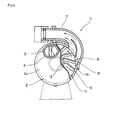
- a pressurizing centrifugal pump 1 includes a case 2 having a drum shape and including an intake port 3 and a feed port 6 as shown in Fig. 6 to Fig. 7 , and the case 2 includes a pressurizing case 2a having the intake port 3 and an impeller case 2b having the feed port 3 on the left side and the right side as a pair.
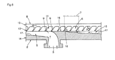
- the pressurizing case 2a includes a pressurizing portion 14 formed integrally with a case lid portion having an intake pipe 4, the pressurizing portion 14 fitting into an opening of the impeller case 2b in a state an impeller 8 is assembled thereto, and the pressurizing case 2a and the impeller case 2b are fixedly fastened by a fixture, whereby the case 2 is formed in a closed state. Accordingly, a pump chamber 13 (a pressurizing chamber 15 in Fig. 8 ) for pressurizing fluid sucked from the intake port 3 via the impeller 8 and feeding out from the feed port 6 is formed between the pressurizing portion 14 and the impeller 8.
- the impeller case 2b is integrally formed with a peripheral wall having a width which allows fitting of the impeller 8 and the pressurizing portion 14 of the pressurizing case 2a on the outer periphery of a disk-shaped side wall.
- the feed port 6 having a predetermined length extending across plural blades 9, 9, ... is formed at a predetermined portion opposing the blade width of the impeller 8. Then, a feed pipe 7 curved in the direction of feeding the fluid is integrally connected to the feed port 6.
- the side wall of the impeller case 2b is integrally coupled with a supporting portion on the outside thereof, and rotatably supports a pump shaft by placing the same at a center portion of the pump chamber 13.
- the impeller 8 is integrally formed with a cylindrical boss portion 12 which also serves as a mounting member with respect to the pump shaft from a center portion of a disk-shaped blade plate 10, which corresponds to the blade-side wall.
- the respective blades 9 are projected radially from the blade plate 10 and the boss portion 12 at predetermined intervals, and a space portion formed by the respective blades 9, the blade plate 10 and the boss portion 12 correspond to impeller chambers 11 which contain the fluid in the interior thereof.
- the boss portion 12 and side ends of the blades 9 of the impeller 8 are formed at substantially the same level, so that end surface of the boss portion 12 is brought into proximity to end surface of a flat shaped partitioning wall 19 formed at a center portion of the pressurizing case 2a when being mounted on the impeller case 2b, and an abrasion resistant member is interposed between the both members for shielding.
- the blades 9 of the impeller 8 are projected radially from the boss portion 12 toward the upstream side in the direction of rotation of the impeller on one side surface of the disk-shaped blade plate 10, and the flat-panel shaped blade strips are bent at midsections of the length thereof so as to be tilted rearward in side view.
- a forward tilting angle (rake angle) ⁇ is provided as shown in Fig. 8 so as to be inclined toward the downstream side in the direction of rotation of the impeller 8.
- the fluid can easily be raked up from the intake port 3 along with the rotation of the impeller 8, whereby the fluid is held in the impeller chamber 11. Then, the respective blades 9 push out and urge the fluid in the impeller chambers 11 as if causing the same to kick while applying a centrifugal force by the blade shape tilted rearward when reaching the portion of the feed port 6, thereby enhancing the flow pressure in the centrifugal direction and increasing the feeding efficiency of the fluid.
- the pump chamber 13 includes an intake chamber 5 which promotes sucking of the fluid and the pressurizing chamber 15 communicating therewith and pressurizing the fluid.
- a pressurizing partitioning wall 16 which is in the proximity to side surfaces of the plural blades 9 and restricts the leakage of the fluid in the impeller chambers 11 so as to have a flat shape flush with the partitioning wall 19 in Fig. 7 . Accordingly, formed around the partitioning wall 19 opposing the end surface of the boss portion 12 of the impeller 8 is a series of the intake chamber 5, the pressurizing chamber 15, and the pressurizing partitioning wall 16.
- a pressurizing plane 17 formed of a smooth tilted surface in a range from the intake port 3 to the pressurizing partitioning wall 16 forms the pressurizing chamber 15 gradually approaching the blades 9 from the side of the intake chamber 5 in a converging manner. Accordingly, the fluid sucked from the intake port 3 into the pump chamber 13 is pressurized gradually by the plural blades 9 via the pressurizing chamber 15 as a long channel in a state of being raked and held in the respective impeller chambers 11 in sequence by the rotation of the impeller 8.
- the pressurizing plane 17 is formed to a pressurization terminal point 18 which is located at a starting end of the pressurizing partitioning wall 16, and pressurizes and guides the fluid moving from the intake chamber 5 toward the downstream side into the impeller chambers 11 by causing the same to flow along the pressurizing plane 17. Also, the fluid is pressurized in the chamber 13 without causing abrupt pressure fluctuations and the fluid pressurized to a maximum pressure at the position of the pressurization terminal point 18 is efficiently pushed out from the feed port 6.
- the fluid and the air bubbles in the pressurizing chamber 15 are pressurized along the pressurizing plane 17 and enter the impeller chamber 11 while increasing in pressure thereof and reach the pressurizing partitioning wall 16, then become a most pressurized state and are added with a pushing-out force and a centrifugal force caused by the shape of the pressurizing plane 17 and the rotation of the blades 9, and fed out from the feed port 6.
- the pressurizing centrifugal pump 1 is developed for the purpose of obtaining a high pumping performance, that is, a high discharging amount by positively involving gas.
- the inventors focused on the actions of pressurization, compression, stirring, mixing, centrifugation, impulse waves of cavitation in the pump, and studied the processing apparatus which enables efficient dispersion, dissolution, solubilization, and emulsification of gas into liquid by applying this technique and, in addition, enables dispersion, dissolution, solubilization, and emulsification of the liquid to heterogeneous liquid.
- the invention has following characteristics.
- a processing apparatus for dispersion, dissolution, solubilization, or emulsification of gas/liquid or liquid/liquid configured to disperse, dissolve, solubilize, or emulsify gas into liquid or disperse, dissolve, solubilize, or emulsify liquid to liquid, including:
- the first processing apparatus for gas/liquid or liquid/liquid dispersion, dissolution, solubilization, or emulsification described above including a valve which can adjust the width of the minute opening of the nozzle portion by a valve body.
- the nozzle portion configured to allow the fluid pressurized by the pressurizing centrifugal pump to pass therethrough and the chamber configured to be capable of storing the fluid passed through the nozzle portion, whereby the fluid is caused to circulate through the pressurizing centrifugal pump, the nozzle portion, and the chamber.
- the fluid When the pressurizing centrifugal pump is driven, in the pump, the fluid is discharged from the feed port under the pressurized state upon being subject to actions such as pressurization, compression, stirring, mixing, centrifugation, cavitation, and the like.
- the gas/liquid or liquid/liquid fluid dispersion, dissolution, solubilization, or emulsification of the discharged fluid is further encouraged upon being subject to pressurization, compression, change in flow velocity or the like by the action of the nozzle portion at the downstream of the pressurizing centrifugal pump, and foam is typically generated.
- the fluid passed through the minute opening of the nozzle portion is received once in the large-capacity chamber as a pool for controlling the pressure and hence is alleviated in pressure, whereby the fluid is stably uniformized. Furthermore, the fluid in the chamber is returned to the intake port of the pressurizing centrifugal pump by the circulating channel, and the process described above is repeated. Accordingly, uniform dispersion, dissolution, solubilization, and emulsification of the gas/liquid or liquid/liquid fluid is achieved.
- the nozzle portion and the chamber cooperate with the function of the pressurizing centrifugal pump, and act to enhance the efficiency of dispersion, dissolution, solubilization, emulsification, and hence the compressed bubble release or the like is enabled.
- the pressurization, compression, stirring, mixing, centrifugation, cavitation and bubbling or the like can be performed simultaneously and efficiently in one process, whereby uniform dispersion, dissolution and solubilization of gas into liquid, and uniform dispersion, dissolution, solubilization, and emulsification of liquid such as gel or viscous liquid or the like into heterogeneous liquid can be performed by a large capacity and in a short time.
- the processing apparatus enables simplification of production facilities, energy saving, high production efficiency, and reduction of production cost or the like in various fields such as foods, beverages, cosmetics, drugs and medicines, sanitary materials, environments.
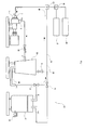
- Fig. 1 is a drawing schematically showing an embodiment of a processing apparatus for dispersion, dissolution, solubilization, or emulsification of gas/liquid, or liquid/liquid (hereinafter, referred to as "processing apparatus").
- a processing apparatus 20 of the embodiment includes a pressurizing centrifugal pump 1 and a circulating portion 25 communicating therewith.
- the circulating portion 25 communicates with an intake port 3 and a feed port 6 of the pressurizing centrifugal pump 1, and constitutes a circulating channel 26 together with the pressurizing centrifugal pump 1.
- a nozzle portion 30 Provided on the downstream of the pressurizing centrifugal pump 1 of the circulating portion 25 is a nozzle portion 30 further on the downstream of the nozzle portion 30 of the circulating portion 25 is a chamber 50.
- the pressurizing centrifugal pump 1 the one known in the related art can be used and, for example, the one having configurations described in Patent Documents 1 to 5, may be used. In this embodiment, the one having configurations shown in Fig. 6 to Fig. 8 is used.
- the pressurizing centrifugal pump 1 includes a pump chamber 13 in a drum-shaped case 2 having the intake port 3 and the feed port 6, in which a pressurizing portion 14 having a pressurizing plane 17 which opposes blades 9 and forms a pressurizing chamber 15 and is converged from the side of the intake port 3 toward the side of the feed port 6 and a pressurizing partitioning wall 16 provided in the proximity of a side surface of the blades 9 and configured to prevent leakage of fluid in an impeller chamber 11 are provided so as to oppose an impeller 8 having the plural blades 9 projecting radially so as to have a retracted angle in the direction of rotation from a boss portion 12 on side surfaces of blade plates 10.
- the fluid and air bubbles in the pressurizing chamber 15 are pressurized along the pressurizing plane 17 and enter the impeller chamber 11 while increasing in pressure thereof and reach the pressurizing partitioning wall 16, then become a most pressurized state and are added with a pushing-out force and a centrifugal force caused by the shape of the pressurizing plane 17 and the rotation of the blades 9, and fed out from the feed port 6.
- the circulating channel 26 may be formed of a conduit such as a pipe formed of a suitable material such as metals or the like considering the fluid pressure or the like.
- the nozzle portion 30 provided on the downstream of the pressurizing centrifugal pump 1 has a minute opening which allows passage of the fluid pressurized by the pressurizing centrifugal pump 1, and the fluid pressurized by the pressurizing centrifugal pump 1 is subject to pressurization, compression, and change in flow velocity or the like at the nozzle portion 30 and hence foam typically, whereby dispersion, dissolution, solubilization or emulsification of the fluid are encouraged.
- the nozzle portion 30 in the present invention has a general action as a nozzle, that is, an action to control the characteristics of the fluid such as flow rate, flow velocity, direction and pressure, and is not necessarily limited to be a tubular shape and is to be broadly interpreted as long as it has a minute opening to discharge the fluid (has a configuration which causes the fluid to pass through a narrow hole).
- a gap between a valve body and a valve seat surface of the valve is included, which allow adjustment of the width of the minute opening by the valve body.
- the valve described above include, for example, needle valves, gate valves, glove valves, ball valves, port valves, and butterfly valves or the like.
- a valve 35 shown in Fig. 2 may be employed, for example.
- the valve 35 is provided with a Venturi tube 37 which is reduced in diameter in a tapered shape along the direction of inflow of the fluid from a fluid inlet port 38 in the interior of a valve body 36 having the fluid inlet port 38 and a fluid outlet port 39 formed so as to cause fluid to flow in the direction perpendicular, a valve element 40 provided at a rear end portion of the Venturi tube 37 so as to be capable of moving back and forth in this direction, whereby the nozzle portion 30 having a minute opening 31 as a gap between the valve element 40 and the rear end portion of the Venturi tube 37 is achieved.
- the needle-shaped valve element 40 configuring a gate valve approaches the surface of the rear end portion of the Venturi tube 37 from the side opposite from the flow channel, so that the nozzle diameter (the width of the minute opening 31) is controlled.
- the fluid discharged from the pressurizing centrifugal pump 1 in Fig. 1 flows from the fluid inlet port 38 of the valve 35 in Fig. 2 , flows from a wider diameter toward a narrower diameter of the tapered Venturi tube 37, passes through the minute opening 31 having a narrower diameter at a distal end of the taper, and is discharged from the fluid outlet port 39.
- the flow velocity (the dynamic pressure of a pressure component in the direction of the flow velocity) is decreased and the static pressure (the pressure component perpendicular to the direction of the flow velocity) is increased when the fluid passes through the larger diameter, while the flow velocity is increased and the static pressure is decreased when the fluid passes through the smaller diameter on the basis of the Bernoulli's theorem. Therefore, when the fluid passes through the larger diameter, the gas is under the conditions of being dissoluble in liquid, and when the fluid passes through the smaller diameter, the gas is in the state of being hardly dissoluble in liquid, thereby generating air bubbles.
- the air bubbles generated in the vicinity of the nozzle portion 30 are encouraged to become finer bubbles by a shear stress and a pressure difference (an abrupt decrease in dynamic pressure) when sneaking through the minute opening 31 having further narrower diameter. Therefore, the diameter of the bubble is determined depending on the difference in diameter of the taper, and the diameters of the bubbles or the state of distribution can be controlled according to the extent of screwing-in of the needle-shaped valve element 40.
- the chamber 50 in Fig. 1 serves as a pool for controlling the pressure, receives the fluid discharged from the minute opening of the nozzle portion 30 once, alleviates the pressure, and stably uniformizes the fluid.
- a lid member of the chamber 50 is provided with a safety valve 51, so that the pressure in the sealed chamber 50 can be released by opening the safety valve 51.
- a liquid sample storage tank 60 and a gas sample storage tank 61 are connected to the circulating portion 25 via mixers 65, 66 to introduce the liquid 60 stored in the liquid sample storage tank 60 and the gas stored in the gas sample storage tank 61 into the circulating portion 25.
- the liquid sample storage tank 60 and the gas sample storage tank 61 are provided as needed and, for example, the liquid may be introduced directly into the circulating portion 25 from the supply source.
- Introduction of the gas into the pressurizing centrifugal pump 1, for example, may be achieved by self supply of the pressurizing centrifugal pump 1 or through a gas mixing hole provided on the pressurizing centrifugal pump 1.
- the mixers 65, 66 may have a configuration in which a flow channel having a check valve can be merged with another flow channel.
- a storage tank 80 for sample after the process is connected to the circulating portion 25 via flow-channel switching valves 70, 71 and the sample after the process is stored therein so as to be taken out from a takeout port 81 arbitrarily.
- dissolution, solubilization, and emulsification of gas into liquid are performed as follows.
- Liquid sample and gas sample are flowed into the circulating portion 25 via the mixers 65, 66 from the liquid sample storage tank 60 and the gas sample storage tank 61, respectively, and the gas/liquid fluid is circulated in the circulating portion 25 by driving the pressurizing centrifugal pump 1.
- the fluid is discharged from the feed port 6 under the pressurized state upon being subject to actions such as pressurization, compression, stirring, mixing, centrifugation, cavitation, and the like.
- the gas/liquid dispersion, dissolution, solubilization, and emulsification of the discharged fluid are further encouraged upon being subject to pressurization or change in flow velocity or the like by the action of the nozzle portion 30 of the pressurizing centrifugal pump 1 on the downstream thereof, and fine foam is typically generated.
- the valve element 40 of the valve 35 as shown in Fig. 2 is moved to reduce the minute opening 31 of the nozzle portion 30, the fluid pressure between the pressurizing centrifugal pump 1 and the nozzle portion 30 is abruptly increased, and reaches equilibrium in a pressurized state. Then, the compressed bubble release occurs at the nozzle portion 30.
- the fluid after foaming passed through the minute opening of the nozzle portion 30 is received once in the large-capacity chamber 50 as a pool for controlling the pressure and hence is alleviated in pressure, whereby the gas/liquid dispersion, dissolution, solubilization, and emulsification are encouraged and hence the fluid is stably uniformized.
- the fluid in the chamber 50 is returned to the intake port 3 of the pressurizing centrifugal pump 1 by the circulating channel 26, and the process described above is repeated.
- the nozzle portion 30 and the chamber 50 cooperate with the function of the pressurizing centrifugal pump 1, and act to enhance the efficiency of dispersion, dissolution, solubilization and emulsification.
- the pressurization, compression, stirring, mixing, centrifugation, cavitation, and bubbling or the like can be performed simultaneously in one process and efficiently, whereby the uniform dispersion, dissolution, solubilization, and emulsification of gas into liquid can be performed by a large capacity and in a short time.
- the uniform dispersion, dissolution, solubilization, and emulsification of liquid such as gel or viscous liquid to heterogeneous liquid can be performed by a large capacity and in a short time by the similar action as that in the case of the gas/liquid system described above.
- the processing apparatus enables uniform dispersion, dissolution, solubilization, and emulsification of gas/liquid, liquid/liquid and, for example, may be used for manufacturing foods such as fresh cream, butter, mayonnaise, dressing, juice, ice cream, homogenized milk, jelly, and the like.
- the invention enables uniform mixture of gas/liquid, liquid/liquid and may be used, for example, for manufacturing aerosol such as aromatic substance, or cosmetics such as emulsion, cream, gel.
- the invention facilitates manufacture of carbonated water, oxygen water, hydrogen water, ozone water, and the like and, in particular, may be used for manufacturing healthy drinks such as mineral water, sport drink, jelly drink.
- the invention may be used for manufacturing infusion solution having an antioxidant potential and a radical oxygen eliminating potential such as reduced hydrogen water or drugs and medicines such as drug solution.
- the invention may be used for manufacturing sanitary materials intended for antibacterial properties, sterilization properties, and mold-free properties such as manufacture of ozone water controlled in concentration, or an application in an environmental field.
- the invention may be used in an application to an environmental field which contributes to energy saving and reduction of CO 2 release by manufacturing emulsion fuel formed of light gas oil/air or light gas oil/air/water.
- the invention may be used in an application to an environmental field which contributes to energy saving and reduction of CO 2 release by manufacturing emulsion fuel formed of heavy oil (C)/water or heavy oil/water/air.
- a pressurizing centrifugal pump manufactured by Yonehara Gikensha having a motor of 3.7 kw mounted thereon, a valve provided with a nozzle portion with a Venturi tube as shown in Fig. 2 and a chamber were connected using a stainless pipe (SUS32) as shown in Fig. 1 to configure a circulating portion in which sample liquid was to be circulated.
- the chamber was filled with 30L of water, and the apparatus was activated at three-phase 200V, a frequency of 60Hz via an inverter at the number of revolutions of 4000.
- the circulating flow rate was set to approximately 100 L/min, the diameter of the nozzle portion of the valve was adjusted by a valve body, and the static pressure on the discharging side of the pressurizing centrifugal pump was maintained at 0.4 MPa.
- the circulating portion was filled with carbonated gas (CO 2 ) at a flow rate of 3L/min from a gas sample storage tank on the side of an air-inlet port of the pressurizing centrifugal pump. Accordingly, the carbonated gas and the water were subjected to compression, stirring and the like in the pressurizing centrifugal pump and were discharged toward the chamber, foamed via the nozzle portion with the Venturi tube at a midsection, and reached the chamber and, in this process, the carbonated gas was dissolved in the water.
- CO 2 carbonated gas
- the circulation was performed under the conditions of being opened to the atmospheric air in a state in which a lid of the chamber was opened. Under such conditions, part of the dissolved carbonated gas can escape to the atmospheric air.
- the sample passed through the chamber and returned back to the pressurizing centrifugal pump, while carbonated gas was replenished again from the gas sample storage tank immediately before the pump. This cycle is determined as a circulation, so that 30L of sample liquid circulates approximately 3.3 times per minute.
- the amount of the carbonated gas dissolved in water was estimated from a standard curve by measuring pH of the solution (HORIBA pH METER F-52). The result is shown in Table 1.
- the chamber was filled with 30L of water, and the apparatus was activated at three-phase 200V, a frequency of 60Hz via the inverter at the number of revolutions of 4000.
- the circulating flow rate was set to approximately 100 L/min, the diameter of the nozzle portion of the valve was adjusted by the valve body, and the static pressure on the discharging side of the pressurizing centrifugal pump was maintained at 0.4 MPa.
- the circulating portion was filled with oxygen gas (O 2 ) at a flow rate of 2L/min from the gas sample storage tank on the side of an air-inlet port of the pressurizing centrifugal pump. Accordingly, the oxygen gas and the water were subjected to compression, stirring and the like in the pressurizing centrifugal pump and were discharged toward the chamber, foamed via the nozzle portion with the Venturi tube at the midsection, and reached the chamber and, in this process, the oxygen gas was dissolved in the water.
- oxygen gas O 2
- the amount of the oxygen gas dissolved in water was estimated from a standard curve by measuring pH of the solution (HORIBA DO MEER OM-51). The result is shown in Table 2.
- the dissolved amount of the oxygen gas was gradually increased along with the circulation of the sample liquid, and after approximately 18 minutes, the scale over of a gauge was resulted.
- the dissolution equilibrium condition seemed to be still to come.
- the circulation was performed under the conditions of being opened to the atmospheric air in a state in which the lid of the chamber was opened.
- manufacture of oxygen water at a higher concentration is enabled by driving the chamber in a sealed state and increasing the amount of infused oxygen.
- the chamber was filled with 30L of water, and the apparatus was activated at three-phase 200V, a frequency of 60Hz via the inverter at the number of revolutions of 4000.
- the circulating flow rate was set to approximately 100 L/min, the diameter of the nozzle portion of the valve was adjusted by the valve body, and the static pressure on the discharging side of the pressurizing centrifugal pump was maintained at 0.3 MPa.
- the circulating portion was filled with hydrogen gas (H 2 ) at a flow rate of 1.5L/min from the gas sample storage tank on the side of an air-inlet port of the pressurizing centrifugal pump. Accordingly, the hydrogen gas and the water were subjected to compression, stirring and the like in the pressurizing centrifugal pump and were discharged toward the chamber, foamed via the nozzle portion with the Venturi tube at the midsection, and reached the chamber and, in this process, the hydrogen gas was dissolved in the water.
- the water temperature at the time of start of the experiment was 25°C
- the water temperature at the time of end after 10 minutes was 32°C.
- the amount of the hydrogen gas dissolved in the water was measured by using KM2100 DH manufactured by KYOEI DENSHI KENKYUJO, and the value of the oxidation-reduction potential (ORP) at that time was measured using HORIBA ORP METER F-52.
- ORP oxidation-reduction potential
- the circulation was performed under the conditions of being opened to the atmospheric air in a state in which the lid of the chamber was opened.
- manufacture of hydrogen water at a higher concentration with high degree of efficient is enabled by driving the chamber in a sealed state so as to reduce the escape of the hydrogen gas to the atmospheric air.
- the chamber was filled with 30L of light gas oil, approximately 100 mL of water, and the apparatus was activated at three-phase 200V, a frequency of 60Hz via an inverter at the number of revolutions of 4000.
- the circulating flow rate was set to approximately 100 L/min, the diameter of the nozzle portion of the valve was adjusted by the valve body, and the static pressure on the discharging side of the pressurizing centrifugal pump was maintained at 0.4 MPa.
- the circulating portion was filled with air at a flow rate of 3L/min from the gas sample storage tank on the side of an air-inlet port of the pressurizing centrifugal pump. Accordingly, the light gas oil and the water and the air were subjected to compression, stirring and the like in the pressurizing centrifugal pump and were discharged toward the chamber, foamed via the nozzle portion with the Venturi tube at the midsection, and reached the chamber and, after 2 to 3 minutes of repetition of this circulation, the light gas oil and the water and the air were turned into emulsion and opacified.
- This opacified state was stably kept for a period on the order of half a day.
- the emulsion manufactured by stirring (hard shaking manually for about 10 minutes) without employing the emulsification on the basis of the processing apparatus of this example returned back to its original phase dissociated state after the elapse of time for about 10 minutes. Therefore, it is estimated that finer vesiculation (emulsification) of light gas oil and water and air has occurred by a mechanical force of the impeller by the high-speed rotation of the pressurizing centrifugal pump, that is, by the shear stress thereof. It is estimated that the constituent of emulsion is formed by cloudy emulsification of micelle of w/o and air bubbles.
- the chamber was filled with 20L of edible formula oil and 10L of edible vinegar, and the apparatus was activated at three-phase 200V, a frequency of 60Hz via the inverter at the number of revolutions of 4000.
- the circulating flow rate was set to approximately 100 L/min, the diameter of the nozzle portion of the valve was adjusted by the valve body, and the static pressure on the discharging side of the pressurizing centrifugal pump was maintained at 0.4 MPa.
- the pressurizing centrifugal pump was activated and circulated for 10 minutes without infusing air into the flow channel by an aspirator on the side of an air-inlet port of the pressurizing centrifugal pump to emulsify (emulsification of) the sample.
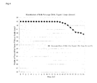
- the emulsified part is transferred from the chamber to a graduated cylinder immediately after the stop of the processing apparatus and the phase dissociated state was observed with time. The result is indicated by solid squares in Fig. 3 .
- the pressurizing centrifugal pump was activated and circulated for 10 minutes while infusing air into the circulating portion by an aspirator on the side of an air-inlet port of the pressurizing centrifugal pump to emulsify (emulsification of) the sample.
- the result is indicated by solid triangles in Fig. 3 .
- the edible formula oil and the edible vinegar of an equal rate were put into a container and were shaken manually for 10 minutes hard, and the phase dissociated state of emulsified part thereafter was observed. The result is indicated by solid diamonds in Fig. 3 .
- the vertical axis indicates the height (mm) of the emulsified state
- the lateral axis indicates the time (minutes).
- Decrease in height of the emulsified state is an index which represents the degree of phase dissociation of the emulsified state (emulsion).
- the result of the emulsified state made manually was decreased abruptly from 95 mm to 75 mm with time and then gradually approached 70 mm.
- the result of emulsification in the processing apparatus was gently decreased from 95 to 85 irrespective of the presence or absence of entrainment of gas, and then a flat state at 85 was maintained.
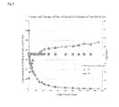
- the chamber was filled with 12L of milk, 12L of yogurt, and 6L of grape extract, and the apparatus was activated at three-phase 200V, a frequency of 60Hz via the inverter at the number of revolutions of 4000.
- the circulating flow rate was set to approximately 100 L/min, the diameter of the nozzle portion of the valve was adjusted by the valve body, and the static pressure on the discharging side of the pressurizing centrifugal pump was maintained at 0.4 MPa.
- the pressurizing centrifugal pump was activated and circulated for 10 minutes while infusing air into the flow channel by an aspirator on the side of an air-inlet port of the pressurizing centrifugal pump to emulsify (emulsification of) the sample.
- the emulsified part is transferred to the graduated cylinder immediately after the stop of the processing apparatus and the phase dissociated state was observed with time. The result is indicated by solid diamonds in Fig. 4 .
- the vertical axis indicates the height (mm) of the emulsified state
- the lateral axis indicates the time (minutes).
- Decrease in height of the emulsified state is an index which represents the degree of phase dissociation of the emulsified state (emulsion).
- the height to 93 mm was maintained until 15 hours had elapsed and little phase dissociated state was recognized. However, the phase dissociation was proceeded from 93 mm to 90 mm from then on.
- the chamber was filled with 30L of distilled water, and the apparatus was activated at three-phase 200V, a frequency of 60Hz via the inverter at the number of revolutions of 4000.
- the circulating flow rate was set to approximately 150 L/min, the diameter of the nozzle portion of the valve was adjusted by the valve body, and the static pressure on the discharging side of the pressurizing centrifugal pump was maintained at 0.5 MPa.
- the pressurizing centrifugal pump was activated and circulated for 10 minutes while infusing hydrogen gas into the flow channel in a rate of 1 L per minute by the aspirator on the side of an air-inlet port of the pressurizing centrifugal pump to emulsify gas-liquid sample, and consequently, hydrogen water was manufactured.
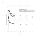
- changes of the amount of dissolved hydrogen, pH, and the oxidation-reduction potential (ORP) with time under the atmospheric air are monitored and the result is shown in Fig. 5 .
- the water temperature at the time of start of the experiment was 7°C, and the water temperature at the time of end thereafter was 15°C.
- the bubble hydrogen refined by the emulsification processing apparatus was dissolved in water efficiently, and hydrogen water having strong reducing characters such as an amount of dissolved hydrogen of 1.2 ppm, a pH of 7.1, and an oxidation-reduction potential of approximately -500mV was obtained.
- the amount of dissolved hydrogen (solid diamond) was abruptly reduced in reverse proportion with time and gradually approached zero after 1500 minutes. At this time, the half-life period of the amount of dissolved hydrogen water was approximately 60 minutes.
- the oxidation-reduction potential (solid triangle) was abruptly increased from the vicinity of - 500 mV until 400 minutes, and then, was increased gently, and then reached a value little smaller +200 mV after 2000 minutes. From these behaviors, it became apparent that reduction of the amount of dissolved hydrogen and increase of the oxidation-reduction potential are correlated.
- the pH value (solid circle) was kept at a constant value 7.1 even though the time had elapsed, that is, even though the dissolved hydrogen flown in all directions in the atmospheric air.
- the result indicates that even though the amount of dissolved hydrogen in water is reduced, the concentration of the hydrogen ion is not affected.
- the reducing character of hydrogen water is estimated to be generated when the hydrogen molecule is dissolved in water by coulomb-coupling the hydrogen molecule weakly to hydron of hydron-hydril (H + -H - ) and oxygen atom, thereby enhancing the effect of the hydril (-H - ) projecting from the water molecule becomes stronger, so that the reducing character is generated.
Landscapes
- Chemical & Material Sciences (AREA)
- Chemical Kinetics & Catalysis (AREA)
- Life Sciences & Earth Sciences (AREA)
- Engineering & Computer Science (AREA)
- Food Science & Technology (AREA)
- Polymers & Plastics (AREA)
- Dispersion Chemistry (AREA)
- Health & Medical Sciences (AREA)
- Nutrition Science (AREA)
- Nuclear Medicine, Radiotherapy & Molecular Imaging (AREA)
- Veterinary Medicine (AREA)
- Medicinal Chemistry (AREA)
- Toxicology (AREA)
- Organic Chemistry (AREA)
- Pharmacology & Pharmacy (AREA)
- Animal Behavior & Ethology (AREA)
- General Health & Medical Sciences (AREA)
- Public Health (AREA)
- General Chemical & Material Sciences (AREA)
- Biochemistry (AREA)
- Pharmaceuticals Containing Other Organic And Inorganic Compounds (AREA)
- Colloid Chemistry (AREA)
- Structures Of Non-Positive Displacement Pumps (AREA)
- Seasonings (AREA)
- Medicinal Preparation (AREA)
- Cosmetics (AREA)
Applications Claiming Priority (2)
| Application Number | Priority Date | Filing Date | Title |
|---|---|---|---|
| JP2009243857 | 2009-10-22 | ||
| PCT/JP2010/068762 WO2011049215A1 (ja) | 2009-10-22 | 2010-10-22 | 気/液または液/液の分散、溶解、可溶化、または乳化用の処理装置 |
Publications (2)
| Publication Number | Publication Date |
|---|---|
| EP2492002A1 true EP2492002A1 (de) | 2012-08-29 |
| EP2492002A4 EP2492002A4 (de) | 2015-08-19 |
Family
ID=43900438
Family Applications (1)
| Application Number | Title | Priority Date | Filing Date |
|---|---|---|---|
| EP10825064.8A Withdrawn EP2492002A4 (de) | 2009-10-22 | 2010-10-22 | Behandlungsvorrichtung zur dispersion, auflösung, kompatibilisierung oder emulgierung von gas/flüssigkeit oder flüssigkeit/flüssigkeit |
Country Status (4)
| Country | Link |
|---|---|
| US (1) | US20120256329A1 (de) |
| EP (1) | EP2492002A4 (de) |
| JP (1) | JP5380545B2 (de) |
| WO (1) | WO2011049215A1 (de) |
Cited By (3)
| Publication number | Priority date | Publication date | Assignee | Title |
|---|---|---|---|---|
| ITUB20155366A1 (it) * | 2015-11-09 | 2017-05-09 | Soc It Acetilene E Derivati S I A D S P A In Breve Siad S P A | Dispositivo e corrispondente metodo per la dispersione di gas in liquidi |
| IT201900010236A1 (it) * | 2019-06-27 | 2020-12-27 | Ats S R L | Processo di preparazione e confezionamento di un prodotto cosmetico e impianto implementante lo stesso |
| CN112337327A (zh) * | 2020-10-29 | 2021-02-09 | 威海金盛泰科技发展有限公司 | 一种纳米气泡发生装置 |
Families Citing this family (16)
| Publication number | Priority date | Publication date | Assignee | Title |
|---|---|---|---|---|
| JP4960435B2 (ja) * | 2009-12-24 | 2012-06-27 | エウレカ・ラボ株式会社 | バブル発生用バルブ装置 |
| JP5686296B2 (ja) * | 2011-10-21 | 2015-03-18 | タカラベルモント株式会社 | 炭酸水吐出装置 |
| JP2013215733A (ja) * | 2013-07-22 | 2013-10-24 | Imacs Kk | 撹拌方法及び循環型ミキサ |
| US20170152853A1 (en) * | 2014-05-21 | 2017-06-01 | Eureka-Lab Inc. | Micronizing device of integrated milling function and vane shearing function |
| WO2016061548A1 (en) * | 2014-10-18 | 2016-04-21 | Abbvie Inc. | Wearable automatic injection system and apparatus |
| JP6670564B2 (ja) * | 2015-07-29 | 2020-03-25 | 東芝ライフスタイル株式会社 | 液体用電磁弁、液体用電磁弁の製造方法、及び洗濯機 |
| JP6327645B2 (ja) * | 2015-10-23 | 2018-05-23 | 光騰國際科技股▲ふん▼有限公司 | 抗酸化機能性飲料、及び抗酸化機能性飲料の製造方法 |
| DE112018006074T5 (de) * | 2017-11-29 | 2020-09-03 | Toshiba Lifestyle Products & Services Corporation | Mikroblasengenerator, Waschmaschine und Haushaltsgerät |
| DE102017011752A1 (de) * | 2017-12-19 | 2019-06-19 | Messer Industriegase Gmbh | Verfahren zum inaktivieren von Mikroorganismen in Lebensmitteln |
| CN108862533A (zh) * | 2018-06-21 | 2018-11-23 | 鲁言和 | 一种氢饮料机 |
| SG11202110542RA (en) * | 2019-03-28 | 2021-10-28 | Nbot Systems LLC | Gas injection systems for optimizing nanobubble formation in a disinfecting solution |
| CN110180455A (zh) * | 2019-07-01 | 2019-08-30 | 上海雷氧企业发展有限公司 | 均质混合设备 |
| CN110681301B (zh) * | 2019-10-11 | 2021-09-03 | 赵云峰 | 一种含富勒烯的牙齿保护剂生产装置 |
| MX2022014083A (es) * | 2020-05-15 | 2023-02-22 | Altered Labs Llc | Kit de tratamiento de suplemento de refuerzo inmunologico y metodos de uso. |
| JP7684064B2 (ja) * | 2021-03-22 | 2025-05-27 | 花王株式会社 | 液体組成物の製造方法 |
| JP2025040348A (ja) * | 2023-09-11 | 2025-03-24 | 株式会社ニクニ | 液体処理装置 |
Family Cites Families (17)
| Publication number | Priority date | Publication date | Assignee | Title |
|---|---|---|---|---|
| BE584488A (de) * | ||||
| US4867918A (en) * | 1987-12-30 | 1989-09-19 | Union Carbide Corporation | Gas dispersion process and system |
| JP3161734B2 (ja) * | 1991-12-02 | 2001-04-25 | テクノロジカル リソーシィズ プロプライエタリー リミテッド | 反応装置 |
| JP4278752B2 (ja) * | 1998-12-16 | 2009-06-17 | 協和機電工業株式会社 | キャビテーション防止機能を備えた気液混合装置 |
| JP3519654B2 (ja) | 1999-12-03 | 2004-04-19 | 米原技研有限会社 | 加圧遠心ポンプ |
| JP4675468B2 (ja) | 2000-09-18 | 2011-04-20 | 米原技研有限会社 | 加圧遠心ポンプ |
| JP4156191B2 (ja) * | 2000-11-22 | 2008-09-24 | 株式会社小松製作所 | エマルジョン製造装置 |
| JP2003117365A (ja) * | 2001-10-19 | 2003-04-22 | Malhaty Pump Mfg Co Ltd | マイクロバブル発生装置 |
| JP4310426B2 (ja) * | 2002-07-25 | 2009-08-12 | 米原技研有限会社 | 加圧遠心ポンプの気体の混入構造 |
| JP2004141868A (ja) * | 2002-09-17 | 2004-05-20 | Chuya Ishibashi | 分散方法 |
| JP4540379B2 (ja) | 2004-03-31 | 2010-09-08 | 米原技研有限会社 | 加圧遠心ポンプ |
| JP4910322B2 (ja) * | 2005-07-19 | 2012-04-04 | 株式会社日立製作所 | 微細気泡を利用した水処理設備 |
| JP4094633B2 (ja) * | 2005-11-30 | 2008-06-04 | ナノバブル株式会社 | 超微細気泡発生装置 |
| JP2007209953A (ja) * | 2006-02-13 | 2007-08-23 | Sharp Corp | 微細気泡発生システム |
| JP2008023435A (ja) * | 2006-07-19 | 2008-02-07 | Kansai Automation Kiki Kk | マイクロバブル発生器 |
| JP2008038619A (ja) | 2006-08-01 | 2008-02-21 | Yonehara Giken Kk | 加圧遠心ポンプ |
| JP2008163858A (ja) * | 2006-12-28 | 2008-07-17 | Kps Kogyo Kk | ポンプユニット |
-
2010
- 2010-10-22 EP EP10825064.8A patent/EP2492002A4/de not_active Withdrawn
- 2010-10-22 WO PCT/JP2010/068762 patent/WO2011049215A1/ja not_active Ceased
- 2010-10-22 JP JP2011537327A patent/JP5380545B2/ja not_active Expired - Fee Related
- 2010-10-22 US US13/503,166 patent/US20120256329A1/en not_active Abandoned
Non-Patent Citations (1)
| Title |
|---|
| See references of WO2011049215A1 * |
Cited By (4)
| Publication number | Priority date | Publication date | Assignee | Title |
|---|---|---|---|---|
| ITUB20155366A1 (it) * | 2015-11-09 | 2017-05-09 | Soc It Acetilene E Derivati S I A D S P A In Breve Siad S P A | Dispositivo e corrispondente metodo per la dispersione di gas in liquidi |
| IT201900010236A1 (it) * | 2019-06-27 | 2020-12-27 | Ats S R L | Processo di preparazione e confezionamento di un prodotto cosmetico e impianto implementante lo stesso |
| CN112337327A (zh) * | 2020-10-29 | 2021-02-09 | 威海金盛泰科技发展有限公司 | 一种纳米气泡发生装置 |
| CN112337327B (zh) * | 2020-10-29 | 2022-08-16 | 威海金盛泰科技发展有限公司 | 一种纳米气泡发生装置 |
Also Published As
| Publication number | Publication date |
|---|---|
| JPWO2011049215A1 (ja) | 2013-03-14 |
| WO2011049215A1 (ja) | 2011-04-28 |
| EP2492002A4 (de) | 2015-08-19 |
| US20120256329A1 (en) | 2012-10-11 |
| JP5380545B2 (ja) | 2014-01-08 |
Similar Documents
| Publication | Publication Date | Title |
|---|---|---|
| EP2492002A1 (de) | Behandlungsvorrichtung zur dispersion, auflösung, kompatibilisierung oder emulgierung von gas/flüssigkeit oder flüssigkeit/flüssigkeit | |
| US10494274B2 (en) | Liquid substance sterilizing method and apparatus | |
| US20130140246A1 (en) | Method and system for enhancing mass transfer in aeration/oxygenation systems | |
| JP5037225B2 (ja) | 有用物質含有ナノバブル発生方法、および有用物質含有ナノバブル発生装置 | |
| US10207204B2 (en) | Liquid processing mixer for mixing a liquid with an additive | |
| JP2011056511A (ja) | 気体混合液生成方法および気体混合液 | |
| JP2011152513A (ja) | 気液混合液生成装置 | |
| JP7116462B2 (ja) | 飲料製造システムおよび飲料製造方法 | |
| JP2011088076A (ja) | 気液混合液の生成方法及び気液混合液生成装置 | |
| CN108289569A (zh) | 混合和发泡设备 | |
| JP2007326101A (ja) | オゾン水処理方法 | |
| CN108348099B (zh) | 离心泵送和发泡设备 | |
| JPH06315617A (ja) | 乳化方法及び乳化装置 | |
| RU123685U1 (ru) | Установка для введения газа ксенона в жидкие среды | |
| US8047702B1 (en) | Continuous high shear mixing process | |
| JP2018088915A (ja) | 飲料製造システムおよび飲料製造方法 | |
| KR20200126528A (ko) | 나노버블발생시스템 | |
| JP4187747B2 (ja) | オゾン水生成装置、オゾン水生成方法及びオゾン水 | |
| CN109772210A (zh) | 一种防团聚固液混合装置 | |
| JP2018122294A (ja) | バブル生成ノズルおよび、これを備えるバブル含有液製造システム | |
| CN105188898A (zh) | 液体处理混合器及方法 | |
| CN208839423U (zh) | 一种乳化罐 | |
| JP2736899B2 (ja) | スラリー調製装置 | |
| JPWO2010134551A1 (ja) | 気液混合液 | |
| JP2010269218A (ja) | 気液混合液の生成方法 |
Legal Events
| Date | Code | Title | Description |
|---|---|---|---|
| PUAI | Public reference made under article 153(3) epc to a published international application that has entered the european phase |
Free format text: ORIGINAL CODE: 0009012 |
|
| 17P | Request for examination filed |
Effective date: 20120427 |
|
| AK | Designated contracting states |
Kind code of ref document: A1 Designated state(s): AL AT BE BG CH CY CZ DE DK EE ES FI FR GB GR HR HU IE IS IT LI LT LU LV MC MK MT NL NO PL PT RO RS SE SI SK SM TR |
|
| DAX | Request for extension of the european patent (deleted) | ||
| RA4 | Supplementary search report drawn up and despatched (corrected) |
Effective date: 20150716 |
|
| RIC1 | Information provided on ipc code assigned before grant |
Ipc: B01F 3/04 20060101AFI20150710BHEP Ipc: B01F 3/08 20060101ALI20150710BHEP Ipc: A23L 2/38 20060101ALI20150710BHEP Ipc: B01F 5/06 20060101ALI20150710BHEP Ipc: A23L 1/24 20060101ALI20150710BHEP Ipc: A47J 43/04 20060101ALI20150710BHEP Ipc: B01F 5/12 20060101ALI20150710BHEP Ipc: B01F 5/10 20060101ALI20150710BHEP Ipc: F04D 29/42 20060101ALI20150710BHEP Ipc: B01F 5/16 20060101ALI20150710BHEP |
|
| STAA | Information on the status of an ep patent application or granted ep patent |
Free format text: STATUS: THE APPLICATION IS DEEMED TO BE WITHDRAWN |
|
| 18D | Application deemed to be withdrawn |
Effective date: 20160216 |