EP2488811B1 - Vorrichtung zur wärmebehandlung von blechbändern - Google Patents
Vorrichtung zur wärmebehandlung von blechbändern Download PDFInfo
- Publication number
- EP2488811B1 EP2488811B1 EP10770943.8A EP10770943A EP2488811B1 EP 2488811 B1 EP2488811 B1 EP 2488811B1 EP 10770943 A EP10770943 A EP 10770943A EP 2488811 B1 EP2488811 B1 EP 2488811B1
- Authority
- EP
- European Patent Office
- Prior art keywords
- bearing
- journal
- tube
- sheet metal
- sliding layer
- Prior art date
- Legal status (The legal status is an assumption and is not a legal conclusion. Google has not performed a legal analysis and makes no representation as to the accuracy of the status listed.)
- Not-in-force
Links
Images

Classifications
-
- C—CHEMISTRY; METALLURGY
- C21—METALLURGY OF IRON
- C21D—MODIFYING THE PHYSICAL STRUCTURE OF FERROUS METALS; GENERAL DEVICES FOR HEAT TREATMENT OF FERROUS OR NON-FERROUS METALS OR ALLOYS; MAKING METAL MALLEABLE, e.g. BY DECARBURISATION OR TEMPERING
- C21D9/00—Heat treatment, e.g. annealing, hardening, quenching or tempering, adapted for particular articles; Furnaces therefor
- C21D9/52—Heat treatment, e.g. annealing, hardening, quenching or tempering, adapted for particular articles; Furnaces therefor for wires; for strips ; for rods of unlimited length
-
- F—MECHANICAL ENGINEERING; LIGHTING; HEATING; WEAPONS; BLASTING
- F27—FURNACES; KILNS; OVENS; RETORTS
- F27D—DETAILS OR ACCESSORIES OF FURNACES, KILNS, OVENS OR RETORTS, IN SO FAR AS THEY ARE OF KINDS OCCURRING IN MORE THAN ONE KIND OF FURNACE
- F27D99/00—Subject matter not provided for in other groups of this subclass
- F27D99/0001—Heating elements or systems
- F27D99/0006—Electric heating elements or system
-
- C—CHEMISTRY; METALLURGY
- C21—METALLURGY OF IRON
- C21D—MODIFYING THE PHYSICAL STRUCTURE OF FERROUS METALS; GENERAL DEVICES FOR HEAT TREATMENT OF FERROUS OR NON-FERROUS METALS OR ALLOYS; MAKING METAL MALLEABLE, e.g. BY DECARBURISATION OR TEMPERING
- C21D1/00—General methods or devices for heat treatment, e.g. annealing, hardening, quenching or tempering
-
- F—MECHANICAL ENGINEERING; LIGHTING; HEATING; WEAPONS; BLASTING
- F23—COMBUSTION APPARATUS; COMBUSTION PROCESSES
- F23C—METHODS OR APPARATUS FOR COMBUSTION USING FLUID FUEL OR SOLID FUEL SUSPENDED IN A CARRIER GAS OR AIR
- F23C3/00—Combustion apparatus characterised by the shape of the combustion chamber
- F23C3/002—Combustion apparatus characterised by the shape of the combustion chamber the chamber having an elongated tubular form, e.g. for a radiant tube
-
- F—MECHANICAL ENGINEERING; LIGHTING; HEATING; WEAPONS; BLASTING
- F27—FURNACES; KILNS; OVENS; RETORTS
- F27D—DETAILS OR ACCESSORIES OF FURNACES, KILNS, OVENS OR RETORTS, IN SO FAR AS THEY ARE OF KINDS OCCURRING IN MORE THAN ONE KIND OF FURNACE
- F27D99/00—Subject matter not provided for in other groups of this subclass
- F27D99/0001—Heating elements or systems
- F27D99/0033—Heating elements or systems using burners
- F27D99/0035—Heating indirectly through a radiant surface
Definitions
- the invention relates to a device for heat treatment of metal strip with at least one jet pipe unit, the three lying in a common plane parallel to the sheet metal strip tubes, namely a connectable to a burner center tube and two connected at both ends to the central tube via elbows outer tubes , And with a support on the opposite side of the burner tube unit for a connected to the two pipe bends between the central tube on the one hand and the two outer tubes on the other hand bearing pin which engages axially displaceable in a pin receiving the support.
- the bearing of the jet pipe unit is to be designed so that at least the thermal expansions of the pipes in the axial direction are taken into account.
- the central tube between the burner and the outer tubes is held axially in a pivot bearing, while at the opposite end of the jet tube unit, a usually hollow bearing pin, which is welded to the two connecting the ends of the central tube to the ends of the outer tubes pipe bends, axially displaceable in supported by a support.
- the invention is therefore based on the object, a device of the type described for the heat treatment of metal bands in such a way that damage to the jet pipe unit due to thermal expansion can be largely excluded.
- the invention solves the problem set by the fact that between the pin receiving the support and the bearing pin a sliding layer forming insert is provided in the support region of the journal.
- an insert with a sliding layer between the bearing pin and the pin receptacle of the support can be prevented in a simple manner a caking of the journal in the pin receiving, so that even at high temperatures, the slidable recording of the journal can be guaranteed in the support.
- Prerequisite is one Sliding layer which has a sufficient temperature resistance, as is advantageous, for example, for sliding layers made of a ceramic material.
- the sliding layer is exposed to a considerable wear due to the relatively high weight load through the nozzle unit, so that a replaceable insert forming the overlay, brings special benefits when it comes to renew the overlay. It only needs to be removed and re-coated or replaced with a new insert.
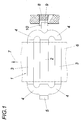
- the illustrated apparatus for heat treatment of metal bands has according to the Fig. 1 at least one nozzle tube unit 1, which comprises a central tube 2 and two with the central tube 2 in a common axial plane lying, parallel outer tubes 3.
- the outer tubes 3 are connected to the central tube. 2 each fluidly connected via end pipe bends 4.
- the hot exhaust gases flowing into the central pipe 2 from a burner connected to an extension 5 of the center pipe 2 are thus partially recirculated via the two outer pipes 3.
- a dash-dotted lines indicated sheet metal strip 6 is heated, which is guided parallel to the common axial plane of the tubes 2, 3, in a feed direction 7, which extends transversely to the tube axes.
- the jet pipe unit 1 is mounted on both sides of the tubes 2 and 3, so that there is a largely uniform distribution of the weight load on the two lateral supports. While the extension 5 of the central tube 2 receiving, not shown for reasons of clarity support the jet pipe unit 1 sets axially, the opposite support 8 supports the nozzle unit 1 axially slidably. For this purpose, the jet pipe unit 1 carries at the opposite end of the extension 5 of the central tube 2 a usually tubular bearing pin 9 which is axially displaceably supported in a sleeve-shaped pin receptacle 10. How the particular Fig.
- this sleeve-shaped pin receptacle 10 is arranged on a support plate 11 which is fixed to a wall 12 of the nozzle unit receiving the nozzle tube 1 and projects through the thermal insulation 13 of the furnace wall 12 into the furnace chamber.
- a heat-insulating plug 14 within the pin receptacle 10 and the support 8 is provided with a corresponding thermal insulation.
- the bearing pin 9 can be supported slidably in the pin receptacle 10 even at high temperature loads, according to the FIGS. 2 and 3 the sleeve-shaped pin receptacle 10 is provided with a sliding layer 15 forming insert 16 on which the pin 9 rests, so that the lubricity of the bearing pin 9 relative to the support 8 is ensured by a corresponding sliding layer 15.
- This insert 16 is held by means of secured plug-in pin 17 in the sleeve-shaped pin receptacle 10 and can therefore be changed in a simple manner, if the wear of makes this insert 16 formed sliding layer 15 makes such a change required.
- the sliding layer 15 of the insert 16 must be designed to be temperature resistant.
- a sliding layer 15 made of a ceramic material satisfies these conditions in an advantageous manner. The required for the compensation of the thermal expansion of the tubes 2, 3 of the jet pipe unit 1 axial relative movement between the bearing pin 9 and the support 8 is thus ensured even at the high loads occurring by the weight of the nozzle unit 1 and the temperature conditions.
Landscapes
- Engineering & Computer Science (AREA)
- Mechanical Engineering (AREA)
- Chemical & Material Sciences (AREA)
- General Engineering & Computer Science (AREA)
- Combustion & Propulsion (AREA)
- Materials Engineering (AREA)
- Thermal Sciences (AREA)
- Crystallography & Structural Chemistry (AREA)
- Physics & Mathematics (AREA)
- Metallurgy (AREA)
- Organic Chemistry (AREA)
- Heat Treatment Of Strip Materials And Filament Materials (AREA)
- Combustion Of Fluid Fuel (AREA)
- Heat Treatments In General, Especially Conveying And Cooling (AREA)
- Heat Treatment Of Articles (AREA)
- Furnace Details (AREA)
- Gas Burners (AREA)
Description
- Die Erfindung bezieht sich auf eine Vorrichtung zur Wärmebehandlung von Blechbändern mit wenigstens einer Strahlrohreinheit, die drei in einer gemeinsamen, zum Blechband parallelen Ebene liegende Rohre, nämlich ein an einen Brenner anschließbares Mittelrohr und zwei an beiden Enden mit dem Mittelrohr über Rohrbögen verbundene Außenrohre, aufweist, und mit einem Auflager auf der dem Brenner gegenüberliegenden Seite der Strahlrohreinheit für einen mit den beiden Rohrbögen zwischen dem Mittelrohr einerseits und den beiden Außenrohren anderseits verbundenen Lagerzapfen, der axial verschiebbar in eine Zapfenaufnahme des Auflagers eingreift.
- Zur Wärmebehandlung von Blechbändern ist es bekannt (
DE 20 2008 009 065 U1 ), mit Hilfe von Brennern beheizbare Strahlrohreinheiten vorzusehen, die zwei von einem an den Brenner angeschlossenen Mittelrohr ausgehende, parallel zum Mittelrohr in einer gemeinsamen Axialebene liegende Außenrohre aufweisen, sodass mit Hilfe der endseitig über Rohrbögen mit dem Mittelrohr verbundenen Außenrohre jeweils ein Teilstrom der in das Mittelrohr strömenden heißen Abgase des Brenners im Kreislauf geführt werden kann. Das zu behandelnde Blechband, das parallel zur gemeinsamen Axialebene der Rohre der Strahlrohreinheit mit einer quer zu den Rohrachsen verlaufenden Vorschubrichtung gefördert wird, wird über die von den Rohren der Strahlrohreinheit abgestrahlte Wärmestrahlung erwärmt. Wegen der hohen Temperaturen der Strahlrohre ist die Lagerung der Strahlrohreinheit so auszugestalten, dass zumindest die Wärmedehnungen der Rohre in axialer Richtung berücksichtigt werden. Zu diesem Zweck wird das Mittelrohr zwischen dem Brenner und den Außenrohren in einem Schwenklager axial festgehalten, während am gegenüberliegenden Ende der Strahlrohreinheit ein üblicherweise hohler Lagerzapfen, der an den beiden die Enden des Mittelrohrs mit den Enden der Außenrohre verbindenden Rohrbögen angeschweißt ist, axial verschiebbar in einem Auflager abgestützt wird. Aufgrund der hohen Behandlungstemperaturen von beispielsweise 750° C bis 900° C leidet die Festigkeit auch von warmfesten Stählen, was die Gefahr eines Festbackens des Lagerzapfens im Auflager mit sich bringt. Mit dem Verhindern der axialen Zapfenbewegung im Auflager kommt es zu Verformungen der Strahlrohre und in Folge davon zu Beschädigungen, die einen Stillstand der Vorrichtung bedingen können. - Der Erfindung liegt somit die Aufgabe zugrunde, eine Vorrichtung der eingangs geschilderten Art zur Wärmebehandlung von Blechbändern so auszugestalten, dass eine Beschädigung der Strahlrohreinheit aufgrund von Wärmedehnungen weitgehend ausgeschlossen werden kann.
- Die Erfindung löst die gestellte Aufgabe dadurch, dass zwischen der Zapfenaufnahme des Auflagers und dem Lagerzapfen ein eine Gleitschicht bildender Einsatz im Auflagebereich des Lagerzapfens vorgesehen ist.
- Durch das Vorsehen eines Einsatzes mit einer Gleitschicht zwischen dem Lagerzapfen und der Zapfenaufnahme des Auflagers kann in einfacher Weise einem Festbacken des Lagerzapfens in der Zapfenaufnahme vorgebeugt werden, sodass auch bei hohen Temperaturen die gleitfähige Aufnahme des Lagerzapfens im Auflager gewährleistet werden kann. Voraussetzung ist eine Gleitschicht, die eine ausreichende Temperaturbeständigkeit aufweist, wie dies beispielsweise für Gleitschichten aus einem keramischen Werkstoff vorteilhaft gegeben ist. Durch das vorsehen eines die Gleitschicht bildenden Einsatzes im Auflagebereich des Lagerzapfens zwischen der Zapfenaufnahme und dem Zapfen ergeben sich einfache Konstruktionsverhältnisse, weil der Einsatz, vorzugsweise ein entsprechend geformter Blechteil, als gesonderter Bauteil einfach mit einer Gleitschicht beschichtet werden kann. Außerdem ist die Gleitschicht aufgrund der vergleichsweise hohen Gewichtsbelastung durch die Strahlrohreinheit einem nicht unerheblichen Verschleiß ausgesetzt, sodass ein auswechselbarer Einsatz, der die Gleitschicht bildet, besondere Vorteile mit sich bringt, wenn es gilt, die Gleitschicht zu erneuern. Es braucht ja lediglich der Einsatz ausgebaut und neu beschichtet bzw. durch einen neuen Einsatz ersetzt zu werden.
- In der Zeichnung ist der Erfindungsgegenstand beispielsweise dargestellt. Es zeigen
-
Fig. 1 eine erfindungsgemäße Vorrichtung zur Wärmebehandlung von Blechbändern ausschnittsweise im Bereich der Strahlrohreinheit in einer vereinfachten Seitenansicht, -
Fig. 2 die Strahlrohreinheit ausschnittsweise im Bereich des Lagerzapfens in einem vereinfachten Schnitt durch das Auflager für den Lagerzapfen in einem größeren Maßstab und -
Fig. 3 einen Schnitt nach der Linie III-III derFig. 2 . - Die dargestellte Vorrichtung zur Wärmebehandlung von Blechbändern weist gemäß der
Fig. 1 wenigstens eine Strahlrohreinheit 1 auf, die ein Mittelrohr 2 und zwei mit dem Mittelrohr 2 in einer gemeinsamen Axialebene liegende, parallele Außenrohre 3 umfasst. Die Außenrohre 3 sind mit dem Mittelrohr 2 jeweils über endseitige Rohrbögen 4 strömungsverbunden. Die von einem an eine Verlängerung 5 des Mittelrohrs 2 angeschlossenen Brenner in das Mittelrohr 2 strömenden heißen Abgase werden somit über die beiden Außenrohre 3 teilweise im Kreislauf geführt. Mit Hilfe der von den Rohren 2, 3 abgestrahlten Strahlungswärme wird ein strichpunktiert angedeutetes Blechband 6 erwärmt, das parallel zur gemeinsamen Axialebene der Rohre 2, 3 geführt wird, und zwar in einer Vorschubrichtung 7, die quer zu den Rohrachsen verläuft. - Die Strahlrohreinheit 1 wird beidseits der Rohre 2 und 3 gelagert, sodass sich eine weitgehend gleichmäßige Aufteilung der Gewichtsbelastung auf die beiden seitlichen Auflager ergibt. Während das die Verlängerung 5 des Mittelrohrs 2 aufnehmende, aus Übersichtlichkeitsgründen nicht dargestellte Auflager die Strahlrohreinheit 1 axial festlegt, stützt das gegenüberliegende Auflager 8 die Strahlrohreinheit 1 axial verschiebbar ab. Zu diesem Zweck trägt die Strahlrohreinheit 1 an dem der Verlängerung 5 gegenüberliegenden Ende des Mittelrohrs 2 einen üblicherweise rohrförmigen Lagerzapfen 9, der axial verschiebbar in einer hülsenförmigen Zapfenaufnahme 10 abgestützt ist. Wie insbesondere der
Fig. 2 zu entnehmen ist, ist diese hülsenförmige Zapfenaufnahme 10 an einer Tragplatte 11 angeordnet, die an eine Wand 12 eines die Strahlrohreinheit 1 aufnehmenden Ofengestells befestigt ist und durch die Wärmedämmung 13 der Ofenwand 12 in den Ofenraum ragt. Durch einen wärmedämmenden Stopfen 14 innerhalb der Zapfenaufnahme 10 ist auch das Auflager 8 mit einer entsprechenden Wärmedämmung versehen. - Damit der Lagerzapfen 9 selbst bei hohen Temperaturbelastungen gleitfähig in der Zapfenaufnahme 10 abgestützt werden kann, ist gemäß den
Fig. 2 und 3 die hülsenförmige Zapfenaufnahme 10 mit einem eine Gleitschicht 15 bildenden Einsatz 16 versehen, auf dem der Zapfen 9 aufruht, sodass die Gleitfähigkeit des Lagerzapfens 9 gegenüber dem Auflager 8 durch eine entsprechende Gleitschicht 15 sichergestellt wird. Dieser Einsatz 16 wird mit Hilfe gesicherter Steckzapfen 17 in der hülsenförmigen Zapfenaufnahme 10 gehalten und kann daher in einfacher Weise gewechselt werden, falls der Verschleiß der durch diesen Einsatz 16 gebildeten Gleitschicht 15 einen solchen Wechsel erforderlich macht. - Die Gleitschicht 15 des Einsatzes 16 muss entsprechend temperaturfest ausgebildet sein. Eine Gleitschicht 15 aus einem keramischen Werkstoff erfüllt diese Bedingungen in vorteilhafter Weise. Die für den Ausgleich der Wärmedehnungen der Rohre 2, 3 der Strahlrohreinheit 1 erforderliche axiale Relativbewegung zwischen dem Lagerzapfen 9 und dem Auflager 8 ist damit auch bei den auftretenden hohen Belastungen durch das Gewicht der Strahlrohreinheit 1 und die Temperaturverhältnisse gewährleistet.
Claims (3)
- Vorrichtung zur Wärmebehandlung von Blechbändern (6) mit wenigstens einer Strahlrohreinheit (1), die drei in einer gemeinsamen, zum Blechband (6) parallelen Ebene liegende Rohre, nämlich ein an einen Brenner anschließbares Mittelrohr (2) und zwei an beiden Enden mit dem Mittelrohr (2) über Rohrbögen (4) verbundene Außenrohre (3), aufweist, und mit einem Auflager (8) auf der dem Brenner gegenüberliegenden Seite der Strahlrohreinheit (1) für einen mit den beiden Rohrbögen (4) zwischen dem Mittelrohr (2) einerseits und den beiden Außenrohren (3) anderseits verbundenen Lagerzapfen (9), der axial verschiebbar in eine Zapfenaufnahme (10) des Auflagers (8) eingreift, dadurch gekennzeichnet, dass zwischen der Zapfenaufnahme (10) des Auflagers (8) und dem Lagerzapfen (9) ein eine Gleitschicht (15) bildender Einsatz (16) im Auflagebereich des Lagerzapfens (9) vorgesehen ist.
- Vorrichtung nach Anspruch 1, dadurch gekennzeichnet, dass der die Gleitschicht (15) bildende Einsatz (16) auswechselbar in der Zapfenaufnahme (10) des Auflagers (8) gehalten ist.
- Vorrichtung nach Anspruch 1 oder 2, dadurch gekennzeichnet, dass die Gleitschicht (15) aus einem keramischen Werkstoff hergestellt ist.
Applications Claiming Priority (2)
| Application Number | Priority Date | Filing Date | Title |
|---|---|---|---|
| AT0160909A AT508368B1 (de) | 2009-10-13 | 2009-10-13 | Vorrichtung zur wärmebehandlung von blechbändern |
| PCT/AT2010/000340 WO2011044599A1 (de) | 2009-10-13 | 2010-09-17 | Vorrichtung zur wärmebehandlung von blechbändern |
Publications (2)
| Publication Number | Publication Date |
|---|---|
| EP2488811A1 EP2488811A1 (de) | 2012-08-22 |
| EP2488811B1 true EP2488811B1 (de) | 2017-06-14 |
Family
ID=43416417
Family Applications (1)
| Application Number | Title | Priority Date | Filing Date |
|---|---|---|---|
| EP10770943.8A Not-in-force EP2488811B1 (de) | 2009-10-13 | 2010-09-17 | Vorrichtung zur wärmebehandlung von blechbändern |
Country Status (13)
| Country | Link |
|---|---|
| US (1) | US8877120B2 (de) |
| EP (1) | EP2488811B1 (de) |
| JP (1) | JP2013507525A (de) |
| KR (1) | KR20120099400A (de) |
| CN (1) | CN102713484B (de) |
| AT (1) | AT508368B1 (de) |
| BR (1) | BR112012008659A2 (de) |
| CA (1) | CA2774828A1 (de) |
| MX (1) | MX2012003807A (de) |
| RU (1) | RU2012119517A (de) |
| TW (1) | TW201120391A (de) |
| WO (1) | WO2011044599A1 (de) |
| ZA (1) | ZA201202062B (de) |
Families Citing this family (7)
| Publication number | Priority date | Publication date | Assignee | Title |
|---|---|---|---|---|
| DE202008009065U1 (de) * | 2008-07-04 | 2008-10-09 | WS Wärmeprozesstechnik GmbH | Strahlungsheizanordnung mit Verzugkompensation |
| WO2014072839A1 (en) * | 2013-01-02 | 2014-05-15 | Bisson Massimiliano | Support device for radiant tubes |
| ITUB20152984A1 (it) * | 2015-08-07 | 2017-02-07 | Nicro S P A | Tubo radiante con codolo corrugato. |
| IT201800006668A1 (it) | 2018-06-26 | 2019-12-26 | Massimiliano Bisson | Dispositivo di supporto per tubi radianti |
| BE1027839B1 (fr) * | 2019-12-10 | 2021-07-08 | Drever International Sa | Élément de chauffage radiant à extrémité libre |
| CN114353544A (zh) * | 2021-12-30 | 2022-04-15 | 江苏九新特钢制品有限公司 | 一种防变形双p型辐射管 |
| AT526742B1 (de) | 2022-12-07 | 2024-12-15 | Andritz Ag Maschf | Haltevorrichtung fuer elektrisch beheizte strahlrohre |
Family Cites Families (14)
| Publication number | Priority date | Publication date | Assignee | Title |
|---|---|---|---|---|
| US3920383A (en) * | 1974-06-20 | 1975-11-18 | Electric Furnace Co | Fluted surface heat exchanger |
| LU84040A1 (fr) | 1982-03-26 | 1983-11-17 | Cockerill Sambre Sa | Supports ameliores de corps de chauffe de fours de recuit |
| GB2198486B (en) * | 1986-11-08 | 1991-03-20 | Ae Plc | Bearings |
| FR2643447B1 (fr) | 1989-02-17 | 1991-10-04 | Stein Heurtey | Systeme de tubes radiants pour fours de chauffage |
| DE9306007U1 (de) | 1993-04-21 | 1993-09-09 | LWK-PlasmaCeramic International S.A., Luxembourg | Lagerung von relativbewegten Laufflächen |
| JP3106283B2 (ja) | 1995-04-04 | 2000-11-06 | 新日本製鐵株式会社 | ラジアントチューブの炉内支持構造 |
| JP3549981B2 (ja) | 1996-05-08 | 2004-08-04 | 新日本製鐵株式会社 | 蓄熱交互燃焼式ラジアントチューブの炉内支持構造 |
| JP3327204B2 (ja) * | 1998-03-10 | 2002-09-24 | 住友金属工業株式会社 | ラジアントチューブの支持構造 |
| CN1201097C (zh) * | 2003-02-25 | 2005-05-11 | 吉林大学 | 超声波轴承 |
| CN2697470Y (zh) * | 2003-07-24 | 2005-05-04 | 吴道洪 | 蓄热式燃气辐射管燃烧器 |
| CN100561047C (zh) * | 2007-04-03 | 2009-11-18 | 北京科技大学 | 一种富氧燃烧辐射管加热器 |
| CN201246745Y (zh) | 2008-05-28 | 2009-05-27 | 烟台百思特炉管厂 | 一种悬挂式承重的燃气式加热炉中的w型辐射管装置 |
| DE202008009065U1 (de) * | 2008-07-04 | 2008-10-09 | WS Wärmeprozesstechnik GmbH | Strahlungsheizanordnung mit Verzugkompensation |
| AT508264B1 (de) | 2009-10-13 | 2010-12-15 | Ebner Ind Ofenbau | Vorrichtung zur wärmebehandlung von blechbändern |
-
2009
- 2009-10-13 AT AT0160909A patent/AT508368B1/de not_active IP Right Cessation
-
2010
- 2010-09-17 BR BR112012008659A patent/BR112012008659A2/pt not_active IP Right Cessation
- 2010-09-17 EP EP10770943.8A patent/EP2488811B1/de not_active Not-in-force
- 2010-09-17 US US13/501,555 patent/US8877120B2/en active Active
- 2010-09-17 CN CN201080046580.8A patent/CN102713484B/zh not_active Expired - Fee Related
- 2010-09-17 CA CA2774828A patent/CA2774828A1/en not_active Abandoned
- 2010-09-17 JP JP2012533430A patent/JP2013507525A/ja active Pending
- 2010-09-17 RU RU2012119517/02A patent/RU2012119517A/ru not_active Application Discontinuation
- 2010-09-17 KR KR1020127009321A patent/KR20120099400A/ko not_active Withdrawn
- 2010-09-17 MX MX2012003807A patent/MX2012003807A/es not_active Application Discontinuation
- 2010-09-17 WO PCT/AT2010/000340 patent/WO2011044599A1/de not_active Ceased
- 2010-09-24 TW TW099132281A patent/TW201120391A/zh unknown
-
2012
- 2012-03-20 ZA ZA2012/02062A patent/ZA201202062B/en unknown
Non-Patent Citations (1)
| Title |
|---|
| None * |
Also Published As
| Publication number | Publication date |
|---|---|
| TW201120391A (en) | 2011-06-16 |
| CN102713484B (zh) | 2015-12-16 |
| AT508368B1 (de) | 2011-01-15 |
| WO2011044599A1 (de) | 2011-04-21 |
| CA2774828A1 (en) | 2011-04-21 |
| AT508368A4 (de) | 2011-01-15 |
| ZA201202062B (en) | 2013-05-29 |
| CN102713484A (zh) | 2012-10-03 |
| KR20120099400A (ko) | 2012-09-10 |
| US20120200015A1 (en) | 2012-08-09 |
| JP2013507525A (ja) | 2013-03-04 |
| MX2012003807A (es) | 2012-05-08 |
| BR112012008659A2 (pt) | 2017-06-13 |
| US8877120B2 (en) | 2014-11-04 |
| EP2488811A1 (de) | 2012-08-22 |
| RU2012119517A (ru) | 2013-11-20 |
Similar Documents
| Publication | Publication Date | Title |
|---|---|---|
| AT508368B1 (de) | Vorrichtung zur wärmebehandlung von blechbändern | |
| AT508264B1 (de) | Vorrichtung zur wärmebehandlung von blechbändern | |
| DE3429522C1 (de) | Reaktionsrohrsystem eines Roehrenspaltofens | |
| DE102015013517A1 (de) | Wärmeübertrager | |
| EP1772692A1 (de) | Vorrichtung zur Abkühlung von Abgasen | |
| AT507669B1 (de) | Verfahren zum erwärmen von leichtmetallblöcken | |
| DE2039508C3 (de) | Stoßofen | |
| DE2936199C2 (de) | Verfahren zur Überhitzung gasförmiger Medien | |
| DE3434356C2 (de) | Aufsatzstücke für gekühlte Tragrohre in Erwärmungsöfen | |
| DE3115930A1 (de) | Stossofen zum waermen von stahl | |
| AT526742B1 (de) | Haltevorrichtung fuer elektrisch beheizte strahlrohre | |
| DE3921238A1 (de) | Nachsetzvorrichtung fuer elektroden | |
| DE4203595A1 (de) | Vorrichtung zum abstuetzen von einsatzgut in einem erwaermungsofen | |
| DE102008038889B4 (de) | Vorrichtung zum Aushalsen dickwandiger Rohre | |
| DE102007023381B4 (de) | Vorrichtung zur Verhinderung des Durchschlagens einer Flamm- und/oder Explosionsfront | |
| DE2929322A1 (de) | Anwaermofen | |
| AT402570B (de) | Hochtemperaturmesseinrichtung | |
| DE889305C (de) | Strahlrohrofen | |
| DE1433679C (de) | Haube zum Auffangen und Weiterleiten der heißen Abgase von Stahlwerkskonvertern | |
| EP3851743A1 (de) | Vorrichtung zum abstützen von mindestens zwei strahlheizrohren in einem ofenraum sowie industrieofen | |
| DE4200272A1 (de) | Vorrichtung zum kontrollierten abkuehlen von beton-rippendraht aus der walzhitze | |
| AT27481B (de) | Liegender Koksofen. | |
| DE86837C (de) | ||
| DE1767069C3 (de) | Vorrichtung mit Platinbauteilen zum Erhitzen eines Stromes von Titantetrachloriddampf | |
| DE1601245C (de) |
Legal Events
| Date | Code | Title | Description |
|---|---|---|---|
| PUAI | Public reference made under article 153(3) epc to a published international application that has entered the european phase |
Free format text: ORIGINAL CODE: 0009012 |
|
| 17P | Request for examination filed |
Effective date: 20120315 |
|
| AK | Designated contracting states |
Kind code of ref document: A1 Designated state(s): AL AT BE BG CH CY CZ DE DK EE ES FI FR GB GR HR HU IE IS IT LI LT LU LV MC MK MT NL NO PL PT RO SE SI SK SM TR |
|
| DAX | Request for extension of the european patent (deleted) | ||
| RAP1 | Party data changed (applicant data changed or rights of an application transferred) |
Owner name: EBNER INDUSTRIEOFENBAU GMBH |
|
| GRAP | Despatch of communication of intention to grant a patent |
Free format text: ORIGINAL CODE: EPIDOSNIGR1 |
|
| INTG | Intention to grant announced |
Effective date: 20170303 |
|
| GRAS | Grant fee paid |
Free format text: ORIGINAL CODE: EPIDOSNIGR3 |
|
| GRAA | (expected) grant |
Free format text: ORIGINAL CODE: 0009210 |
|
| AK | Designated contracting states |
Kind code of ref document: B1 Designated state(s): AL AT BE BG CH CY CZ DE DK EE ES FI FR GB GR HR HU IE IS IT LI LT LU LV MC MK MT NL NO PL PT RO SE SI SK SM TR |
|
| REG | Reference to a national code |
Ref country code: GB Ref legal event code: FG4D Free format text: NOT ENGLISH |
|
| REG | Reference to a national code |
Ref country code: CH Ref legal event code: EP Ref country code: AT Ref legal event code: REF Ref document number: 901384 Country of ref document: AT Kind code of ref document: T Effective date: 20170615 |
|
| REG | Reference to a national code |
Ref country code: IE Ref legal event code: FG4D Free format text: LANGUAGE OF EP DOCUMENT: GERMAN |
|
| REG | Reference to a national code |
Ref country code: DE Ref legal event code: R096 Ref document number: 502010013756 Country of ref document: DE |
|
| REG | Reference to a national code |
Ref country code: FR Ref legal event code: PLFP Year of fee payment: 8 |
|
| REG | Reference to a national code |
Ref country code: NL Ref legal event code: MP Effective date: 20170614 |
|
| REG | Reference to a national code |
Ref country code: LT Ref legal event code: MG4D |
|
| PG25 | Lapsed in a contracting state [announced via postgrant information from national office to epo] |
Ref country code: GR Free format text: LAPSE BECAUSE OF FAILURE TO SUBMIT A TRANSLATION OF THE DESCRIPTION OR TO PAY THE FEE WITHIN THE PRESCRIBED TIME-LIMIT Effective date: 20170915 Ref country code: FI Free format text: LAPSE BECAUSE OF FAILURE TO SUBMIT A TRANSLATION OF THE DESCRIPTION OR TO PAY THE FEE WITHIN THE PRESCRIBED TIME-LIMIT Effective date: 20170614 Ref country code: NO Free format text: LAPSE BECAUSE OF FAILURE TO SUBMIT A TRANSLATION OF THE DESCRIPTION OR TO PAY THE FEE WITHIN THE PRESCRIBED TIME-LIMIT Effective date: 20170914 Ref country code: HR Free format text: LAPSE BECAUSE OF FAILURE TO SUBMIT A TRANSLATION OF THE DESCRIPTION OR TO PAY THE FEE WITHIN THE PRESCRIBED TIME-LIMIT Effective date: 20170614 Ref country code: LT Free format text: LAPSE BECAUSE OF FAILURE TO SUBMIT A TRANSLATION OF THE DESCRIPTION OR TO PAY THE FEE WITHIN THE PRESCRIBED TIME-LIMIT Effective date: 20170614 Ref country code: ES Free format text: LAPSE BECAUSE OF FAILURE TO SUBMIT A TRANSLATION OF THE DESCRIPTION OR TO PAY THE FEE WITHIN THE PRESCRIBED TIME-LIMIT Effective date: 20170614 |
|
| PG25 | Lapsed in a contracting state [announced via postgrant information from national office to epo] |
Ref country code: LV Free format text: LAPSE BECAUSE OF FAILURE TO SUBMIT A TRANSLATION OF THE DESCRIPTION OR TO PAY THE FEE WITHIN THE PRESCRIBED TIME-LIMIT Effective date: 20170614 Ref country code: SE Free format text: LAPSE BECAUSE OF FAILURE TO SUBMIT A TRANSLATION OF THE DESCRIPTION OR TO PAY THE FEE WITHIN THE PRESCRIBED TIME-LIMIT Effective date: 20170614 Ref country code: BG Free format text: LAPSE BECAUSE OF FAILURE TO SUBMIT A TRANSLATION OF THE DESCRIPTION OR TO PAY THE FEE WITHIN THE PRESCRIBED TIME-LIMIT Effective date: 20170914 Ref country code: NL Free format text: LAPSE BECAUSE OF FAILURE TO SUBMIT A TRANSLATION OF THE DESCRIPTION OR TO PAY THE FEE WITHIN THE PRESCRIBED TIME-LIMIT Effective date: 20170614 |
|
| PG25 | Lapsed in a contracting state [announced via postgrant information from national office to epo] |
Ref country code: EE Free format text: LAPSE BECAUSE OF FAILURE TO SUBMIT A TRANSLATION OF THE DESCRIPTION OR TO PAY THE FEE WITHIN THE PRESCRIBED TIME-LIMIT Effective date: 20170614 Ref country code: RO Free format text: LAPSE BECAUSE OF FAILURE TO SUBMIT A TRANSLATION OF THE DESCRIPTION OR TO PAY THE FEE WITHIN THE PRESCRIBED TIME-LIMIT Effective date: 20170614 Ref country code: CZ Free format text: LAPSE BECAUSE OF FAILURE TO SUBMIT A TRANSLATION OF THE DESCRIPTION OR TO PAY THE FEE WITHIN THE PRESCRIBED TIME-LIMIT Effective date: 20170614 Ref country code: SK Free format text: LAPSE BECAUSE OF FAILURE TO SUBMIT A TRANSLATION OF THE DESCRIPTION OR TO PAY THE FEE WITHIN THE PRESCRIBED TIME-LIMIT Effective date: 20170614 |
|
| PG25 | Lapsed in a contracting state [announced via postgrant information from national office to epo] |
Ref country code: IS Free format text: LAPSE BECAUSE OF FAILURE TO SUBMIT A TRANSLATION OF THE DESCRIPTION OR TO PAY THE FEE WITHIN THE PRESCRIBED TIME-LIMIT Effective date: 20171014 Ref country code: SM Free format text: LAPSE BECAUSE OF FAILURE TO SUBMIT A TRANSLATION OF THE DESCRIPTION OR TO PAY THE FEE WITHIN THE PRESCRIBED TIME-LIMIT Effective date: 20170614 Ref country code: PL Free format text: LAPSE BECAUSE OF FAILURE TO SUBMIT A TRANSLATION OF THE DESCRIPTION OR TO PAY THE FEE WITHIN THE PRESCRIBED TIME-LIMIT Effective date: 20170614 |
|
| REG | Reference to a national code |
Ref country code: DE Ref legal event code: R097 Ref document number: 502010013756 Country of ref document: DE |
|
| PLBE | No opposition filed within time limit |
Free format text: ORIGINAL CODE: 0009261 |
|
| STAA | Information on the status of an ep patent application or granted ep patent |
Free format text: STATUS: NO OPPOSITION FILED WITHIN TIME LIMIT |
|
| PG25 | Lapsed in a contracting state [announced via postgrant information from national office to epo] |
Ref country code: DK Free format text: LAPSE BECAUSE OF FAILURE TO SUBMIT A TRANSLATION OF THE DESCRIPTION OR TO PAY THE FEE WITHIN THE PRESCRIBED TIME-LIMIT Effective date: 20170614 |
|
| REG | Reference to a national code |
Ref country code: CH Ref legal event code: PL |
|
| 26N | No opposition filed |
Effective date: 20180315 |
|
| GBPC | Gb: european patent ceased through non-payment of renewal fee |
Effective date: 20170917 |
|
| PG25 | Lapsed in a contracting state [announced via postgrant information from national office to epo] |
Ref country code: MC Free format text: LAPSE BECAUSE OF FAILURE TO SUBMIT A TRANSLATION OF THE DESCRIPTION OR TO PAY THE FEE WITHIN THE PRESCRIBED TIME-LIMIT Effective date: 20170614 |
|
| REG | Reference to a national code |
Ref country code: IE Ref legal event code: MM4A |
|
| PG25 | Lapsed in a contracting state [announced via postgrant information from national office to epo] |
Ref country code: LU Free format text: LAPSE BECAUSE OF NON-PAYMENT OF DUE FEES Effective date: 20170917 |
|
| PG25 | Lapsed in a contracting state [announced via postgrant information from national office to epo] |
Ref country code: IE Free format text: LAPSE BECAUSE OF NON-PAYMENT OF DUE FEES Effective date: 20170917 Ref country code: CH Free format text: LAPSE BECAUSE OF NON-PAYMENT OF DUE FEES Effective date: 20170930 Ref country code: GB Free format text: LAPSE BECAUSE OF NON-PAYMENT OF DUE FEES Effective date: 20170917 Ref country code: LI Free format text: LAPSE BECAUSE OF NON-PAYMENT OF DUE FEES Effective date: 20170930 |
|
| PG25 | Lapsed in a contracting state [announced via postgrant information from national office to epo] |
Ref country code: SI Free format text: LAPSE BECAUSE OF FAILURE TO SUBMIT A TRANSLATION OF THE DESCRIPTION OR TO PAY THE FEE WITHIN THE PRESCRIBED TIME-LIMIT Effective date: 20170614 |
|
| REG | Reference to a national code |
Ref country code: FR Ref legal event code: PLFP Year of fee payment: 9 |
|
| PG25 | Lapsed in a contracting state [announced via postgrant information from national office to epo] |
Ref country code: MT Free format text: LAPSE BECAUSE OF FAILURE TO SUBMIT A TRANSLATION OF THE DESCRIPTION OR TO PAY THE FEE WITHIN THE PRESCRIBED TIME-LIMIT Effective date: 20170614 |
|
| PGFP | Annual fee paid to national office [announced via postgrant information from national office to epo] |
Ref country code: FR Payment date: 20180927 Year of fee payment: 9 |
|
| REG | Reference to a national code |
Ref country code: AT Ref legal event code: MM01 Ref document number: 901384 Country of ref document: AT Kind code of ref document: T Effective date: 20170917 |
|
| PGFP | Annual fee paid to national office [announced via postgrant information from national office to epo] |
Ref country code: BE Payment date: 20180925 Year of fee payment: 9 |
|
| PG25 | Lapsed in a contracting state [announced via postgrant information from national office to epo] |
Ref country code: AT Free format text: LAPSE BECAUSE OF NON-PAYMENT OF DUE FEES Effective date: 20170917 |
|
| PGFP | Annual fee paid to national office [announced via postgrant information from national office to epo] |
Ref country code: IT Payment date: 20180927 Year of fee payment: 9 |
|
| PG25 | Lapsed in a contracting state [announced via postgrant information from national office to epo] |
Ref country code: HU Free format text: LAPSE BECAUSE OF FAILURE TO SUBMIT A TRANSLATION OF THE DESCRIPTION OR TO PAY THE FEE WITHIN THE PRESCRIBED TIME-LIMIT; INVALID AB INITIO Effective date: 20100917 |
|
| PG25 | Lapsed in a contracting state [announced via postgrant information from national office to epo] |
Ref country code: CY Free format text: LAPSE BECAUSE OF NON-PAYMENT OF DUE FEES Effective date: 20170614 |
|
| PG25 | Lapsed in a contracting state [announced via postgrant information from national office to epo] |
Ref country code: MK Free format text: LAPSE BECAUSE OF FAILURE TO SUBMIT A TRANSLATION OF THE DESCRIPTION OR TO PAY THE FEE WITHIN THE PRESCRIBED TIME-LIMIT Effective date: 20170614 |
|
| PG25 | Lapsed in a contracting state [announced via postgrant information from national office to epo] |
Ref country code: TR Free format text: LAPSE BECAUSE OF FAILURE TO SUBMIT A TRANSLATION OF THE DESCRIPTION OR TO PAY THE FEE WITHIN THE PRESCRIBED TIME-LIMIT Effective date: 20170614 |
|
| PG25 | Lapsed in a contracting state [announced via postgrant information from national office to epo] |
Ref country code: PT Free format text: LAPSE BECAUSE OF FAILURE TO SUBMIT A TRANSLATION OF THE DESCRIPTION OR TO PAY THE FEE WITHIN THE PRESCRIBED TIME-LIMIT Effective date: 20170614 |
|
| PG25 | Lapsed in a contracting state [announced via postgrant information from national office to epo] |
Ref country code: AL Free format text: LAPSE BECAUSE OF FAILURE TO SUBMIT A TRANSLATION OF THE DESCRIPTION OR TO PAY THE FEE WITHIN THE PRESCRIBED TIME-LIMIT Effective date: 20170614 |
|
| REG | Reference to a national code |
Ref country code: BE Ref legal event code: MM Effective date: 20190930 |
|
| PG25 | Lapsed in a contracting state [announced via postgrant information from national office to epo] |
Ref country code: BE Free format text: LAPSE BECAUSE OF NON-PAYMENT OF DUE FEES Effective date: 20190930 Ref country code: IT Free format text: LAPSE BECAUSE OF NON-PAYMENT OF DUE FEES Effective date: 20190917 |
|
| PG25 | Lapsed in a contracting state [announced via postgrant information from national office to epo] |
Ref country code: FR Free format text: LAPSE BECAUSE OF NON-PAYMENT OF DUE FEES Effective date: 20190930 |
|
| REG | Reference to a national code |
Ref country code: DE Ref legal event code: R082 Ref document number: 502010013756 Country of ref document: DE Representative=s name: ABP BURGER RECHTSANWALTSGESELLSCHAFT MBH, DE |
|
| PGFP | Annual fee paid to national office [announced via postgrant information from national office to epo] |
Ref country code: DE Payment date: 20230816 Year of fee payment: 14 |
|
| REG | Reference to a national code |
Ref country code: DE Ref legal event code: R119 Ref document number: 502010013756 Country of ref document: DE |
|
| PG25 | Lapsed in a contracting state [announced via postgrant information from national office to epo] |
Ref country code: DE Free format text: LAPSE BECAUSE OF NON-PAYMENT OF DUE FEES Effective date: 20250401 |