EP2474792A2 - Chaudière transportant de l'eau, accumulateur-tampon et procédé de fabrication d'un élément mural transportant de l'eau - Google Patents
Chaudière transportant de l'eau, accumulateur-tampon et procédé de fabrication d'un élément mural transportant de l'eau Download PDFInfo
- Publication number
- EP2474792A2 EP2474792A2 EP12000108A EP12000108A EP2474792A2 EP 2474792 A2 EP2474792 A2 EP 2474792A2 EP 12000108 A EP12000108 A EP 12000108A EP 12000108 A EP12000108 A EP 12000108A EP 2474792 A2 EP2474792 A2 EP 2474792A2
- Authority
- EP
- European Patent Office
- Prior art keywords
- wall
- water
- boiler
- reinforcing
- reinforcing element
- Prior art date
- Legal status (The legal status is an assumption and is not a legal conclusion. Google has not performed a legal analysis and makes no representation as to the accuracy of the status listed.)
- Withdrawn
Links
- 239000000872 buffer Substances 0.000 title claims abstract description 64
- 238000004519 manufacturing process Methods 0.000 title claims abstract description 20
- 238000003860 storage Methods 0.000 title abstract description 12
- XLYOFNOQVPJJNP-UHFFFAOYSA-N water Substances O XLYOFNOQVPJJNP-UHFFFAOYSA-N 0.000 claims abstract description 95
- 238000003466 welding Methods 0.000 claims abstract description 44
- 238000002485 combustion reaction Methods 0.000 claims abstract description 38
- 238000000034 method Methods 0.000 claims abstract description 15
- 238000010438 heat treatment Methods 0.000 claims abstract description 14
- 239000002184 metal Substances 0.000 claims abstract description 14
- 229910052751 metal Inorganic materials 0.000 claims abstract description 14
- 230000003014 reinforcing effect Effects 0.000 claims description 123
- 230000015654 memory Effects 0.000 claims description 38
- 239000002023 wood Substances 0.000 claims description 27
- 238000005192 partition Methods 0.000 claims description 18
- 238000002309 gasification Methods 0.000 claims description 13
- 239000002028 Biomass Substances 0.000 claims description 12
- 239000008188 pellet Substances 0.000 claims description 12
- 229910001220 stainless steel Inorganic materials 0.000 claims description 8
- 239000010935 stainless steel Substances 0.000 claims description 8
- 229910000831 Steel Inorganic materials 0.000 claims description 5
- 239000010959 steel Substances 0.000 claims description 5
- 230000002787 reinforcement Effects 0.000 abstract description 3
- 239000000463 material Substances 0.000 description 14
- 239000003546 flue gas Substances 0.000 description 10
- 239000007789 gas Substances 0.000 description 8
- 239000000945 filler Substances 0.000 description 7
- 230000007704 transition Effects 0.000 description 7
- UGFAIRIUMAVXCW-UHFFFAOYSA-N Carbon monoxide Chemical compound [O+]#[C-] UGFAIRIUMAVXCW-UHFFFAOYSA-N 0.000 description 6
- 238000005452 bending Methods 0.000 description 2
- 238000005516 engineering process Methods 0.000 description 2
- 239000000779 smoke Substances 0.000 description 2
- 239000011449 brick Substances 0.000 description 1
- 239000004927 clay Substances 0.000 description 1
- 239000000470 constituent Substances 0.000 description 1
- 238000010276 construction Methods 0.000 description 1
- 230000001419 dependent effect Effects 0.000 description 1
- 238000010304 firing Methods 0.000 description 1
- 239000000446 fuel Substances 0.000 description 1
- 230000005484 gravity Effects 0.000 description 1
- 239000008236 heating water Substances 0.000 description 1
- 150000002739 metals Chemical class 0.000 description 1
- 239000011368 organic material Substances 0.000 description 1
- 238000009436 residential construction Methods 0.000 description 1
- 230000006641 stabilisation Effects 0.000 description 1
- 238000011105 stabilization Methods 0.000 description 1
- 239000002699 waste material Substances 0.000 description 1
Images


Classifications
-
- F—MECHANICAL ENGINEERING; LIGHTING; HEATING; WEAPONS; BLASTING
- F24—HEATING; RANGES; VENTILATING
- F24H—FLUID HEATERS, e.g. WATER OR AIR HEATERS, HAVING HEAT-GENERATING MEANS, e.g. HEAT PUMPS, IN GENERAL
- F24H1/00—Water heaters, e.g. boilers, continuous-flow heaters or water-storage heaters
- F24H1/22—Water heaters other than continuous-flow or water-storage heaters, e.g. water heaters for central heating
- F24H1/24—Water heaters other than continuous-flow or water-storage heaters, e.g. water heaters for central heating with water mantle surrounding the combustion chamber or chambers
- F24H1/26—Water heaters other than continuous-flow or water-storage heaters, e.g. water heaters for central heating with water mantle surrounding the combustion chamber or chambers the water mantle forming an integral body
-
- F—MECHANICAL ENGINEERING; LIGHTING; HEATING; WEAPONS; BLASTING
- F24—HEATING; RANGES; VENTILATING
- F24B—DOMESTIC STOVES OR RANGES FOR SOLID FUELS; IMPLEMENTS FOR USE IN CONNECTION WITH STOVES OR RANGES
- F24B1/00—Stoves or ranges
- F24B1/18—Stoves with open fires, e.g. fireplaces
- F24B1/183—Stoves with open fires, e.g. fireplaces with additional provisions for heating water
-
- F—MECHANICAL ENGINEERING; LIGHTING; HEATING; WEAPONS; BLASTING
- F24—HEATING; RANGES; VENTILATING
- F24C—DOMESTIC STOVES OR RANGES ; DETAILS OF DOMESTIC STOVES OR RANGES, OF GENERAL APPLICATION
- F24C13/00—Stoves or ranges with additional provisions for heating water
-
- F—MECHANICAL ENGINEERING; LIGHTING; HEATING; WEAPONS; BLASTING
- F24—HEATING; RANGES; VENTILATING
- F24H—FLUID HEATERS, e.g. WATER OR AIR HEATERS, HAVING HEAT-GENERATING MEANS, e.g. HEAT PUMPS, IN GENERAL
- F24H9/00—Details
- F24H9/0005—Details for water heaters
- F24H9/001—Guiding means
- F24H9/0015—Guiding means in water channels
-
- F—MECHANICAL ENGINEERING; LIGHTING; HEATING; WEAPONS; BLASTING
- F28—HEAT EXCHANGE IN GENERAL
- F28D—HEAT-EXCHANGE APPARATUS, NOT PROVIDED FOR IN ANOTHER SUBCLASS, IN WHICH THE HEAT-EXCHANGE MEDIA DO NOT COME INTO DIRECT CONTACT
- F28D1/00—Heat-exchange apparatus having stationary conduit assemblies for one heat-exchange medium only, the media being in contact with different sides of the conduit wall, in which the other heat-exchange medium is a large body of fluid, e.g. domestic or motor car radiators
- F28D1/06—Heat-exchange apparatus having stationary conduit assemblies for one heat-exchange medium only, the media being in contact with different sides of the conduit wall, in which the other heat-exchange medium is a large body of fluid, e.g. domestic or motor car radiators with the heat-exchange conduits forming part of, or being attached to, the tank containing the body of fluid
-
- F—MECHANICAL ENGINEERING; LIGHTING; HEATING; WEAPONS; BLASTING
- F28—HEAT EXCHANGE IN GENERAL
- F28D—HEAT-EXCHANGE APPARATUS, NOT PROVIDED FOR IN ANOTHER SUBCLASS, IN WHICH THE HEAT-EXCHANGE MEDIA DO NOT COME INTO DIRECT CONTACT
- F28D20/00—Heat storage plants or apparatus in general; Regenerative heat-exchange apparatus not covered by groups F28D17/00 or F28D19/00
- F28D20/0034—Heat storage plants or apparatus in general; Regenerative heat-exchange apparatus not covered by groups F28D17/00 or F28D19/00 using liquid heat storage material
-
- F—MECHANICAL ENGINEERING; LIGHTING; HEATING; WEAPONS; BLASTING
- F24—HEATING; RANGES; VENTILATING
- F24H—FLUID HEATERS, e.g. WATER OR AIR HEATERS, HAVING HEAT-GENERATING MEANS, e.g. HEAT PUMPS, IN GENERAL
- F24H2230/00—Solid fuel fired boiler
-
- F—MECHANICAL ENGINEERING; LIGHTING; HEATING; WEAPONS; BLASTING
- F28—HEAT EXCHANGE IN GENERAL
- F28F—DETAILS OF HEAT-EXCHANGE AND HEAT-TRANSFER APPARATUS, OF GENERAL APPLICATION
- F28F2225/00—Reinforcing means
- F28F2225/04—Reinforcing means for conduits
-
- Y—GENERAL TAGGING OF NEW TECHNOLOGICAL DEVELOPMENTS; GENERAL TAGGING OF CROSS-SECTIONAL TECHNOLOGIES SPANNING OVER SEVERAL SECTIONS OF THE IPC; TECHNICAL SUBJECTS COVERED BY FORMER USPC CROSS-REFERENCE ART COLLECTIONS [XRACs] AND DIGESTS
- Y02—TECHNOLOGIES OR APPLICATIONS FOR MITIGATION OR ADAPTATION AGAINST CLIMATE CHANGE
- Y02E—REDUCTION OF GREENHOUSE GAS [GHG] EMISSIONS, RELATED TO ENERGY GENERATION, TRANSMISSION OR DISTRIBUTION
- Y02E60/00—Enabling technologies; Technologies with a potential or indirect contribution to GHG emissions mitigation
- Y02E60/14—Thermal energy storage
Definitions
- the present invention relates generally to a water-bearing boiler, a buffer tank and a method of manufacturing a wall member for a boiler, and more particularly to a water-bearing boiler, a buffer tank and a method of manufacturing a water-carrying wall member using laser welding.
- buffer memories are known, which are typically cylindrical. Due to the round shape they need a lot of space, especially a lot of space.
- Object of the present invention is to provide an improved water-bearing boiler, an improved buffer memory and an improved method for producing a wall element for a water-bearing boiler or for a buffer memory available.
- the present invention provides a water-bearing Heating boilers, in particular biomass boilers, such as pellet boilers, firewood boilers and / or wood gasification boilers, ready, comprising: a combustion chamber; and at least one water-conducting wall portion at least partially surrounding the combustion chamber, wherein the at least one water-carrying wall portion has an outer wall, an inner wall and at least one reinforcing element.
- the at least one reinforcing element is arranged between the outer wall and the inner wall and has at least one opening through which water can flow.
- the at least one water-carrying wall section, the outer wall, the inner wall and the at least one reinforcing element are at least partially made of metal.
- the at least one reinforcing element is at least partially welded by means of laser welding from the outside through the outer wall and / or from the outside through the inner wall of the wall section to the inner side of the outer wall and / or the inner side of the inner wall.
- the present invention provides a buffer storage for storing water, the storage tank being adapted to be placed in a heating system for storing hot water.
- the buffer memory comprises: at least two opposite wall sections between which at least one reinforcing element is arranged, which has a plurality of apertures, through which water can flow.
- the at least one reinforcing element is at least partially welded by means of laser welding from the outside through the opposite wall sections, in each case with the inside of the corresponding wall section.
- the present invention provides a method for producing a water-conducting wall element, in particular a water-conducting wall element for a water-bearing boiler according to the first aspect or a buffer memory according to the second aspect.
- the wall element has at least two opposite outer wall elements.
- the method comprises the steps of: arranging at least one outer wall element; Arranging at least one reinforcing element on the inside of the outer wall element; and laser welding through the outside of the outer wall member to weld the reinforcement member to the inside of the outer wall member.
- FIG. 1 An embodiment of a water-bearing boiler in accordance with the present invention is illustrated. Before a detailed description follows first general explanations to the embodiments and their advantages.
- water-bearing boilers are known in which biomass, such as wood, wood chips, pellets or the like is burned to heat water.
- the heated water is typically used for heating and water heating.
- Water-bearing boilers that are suitable for burning pellets and, for example, use a wood gasification process for combustion are exposed to high pressures. Accordingly stable the walls of the boiler are built, which makes them heavy and therefore unwieldy.
- wood gasification boilers are therefore typically constructed of thick sheets with a wall thickness of 5 mm to 8 mm.
- a high total weight of the wood gasification boiler which can be, for example, 500 kg to 600 kg.
- a wood gasification boiler with such a high weight of 500 kg to 600 kg is difficult to transport under certain circumstances, since he is, for example, with two people hard to carry.
- the heating is provided in the basement and the basement is only often accessible via a narrow staircase. In such cases, the transport of a 500 kg wood gasification boiler in the boiler room space can be difficult to implement because, for example, not more than two people can simultaneously attack on the stairs to the wood gasification boiler.
- buffer storage for storing hot water in a heating system are known, which are typically designed cylindrical. Due to the round shape they need a lot of space. This represents a waste of space, especially in houses with little living / usable space. Due to the round shape, storage tanks can not be installed in a space-saving manner, for example directly on the wall or in the corner of a room.
- buffer memory designed as a cylinder, since this form requires as few welds and no stiffening elements.
- the known water-bearing boilers are designed with a thick sheet metal in order to minimize the number of welds possible.
- the inventor has now recognized that by the combination of thin sheet with reinforcing elements, which welded to the relatively complex laser welding technique be a water-bearing lightweight boilers and a buffer memory, which is not cylindrical, can be realized profitably.
- a lightweight boiler weighs, for example, only 200 kg is thus significantly lighter than the known heating boiler made of thick sheet metal, as mentioned above, a weight of, for example. 500 kg to 600 kg.
- the laser welding technique allows welding without filler material and through a material. Accordingly, it is, for example, not necessary to provide a cutout when a seam is not or only poorly accessible.
- For laser welding is relatively complex and associated with high costs.
- the inventor has recognized that by combining thin sheets, for example with a wall thickness of between 1 mm and 2 mm, of reinforcing elements and laser welding, a water-bearing boiler or storage tank with a profitability and stability similar to that of US Pat known boilers and buffers are made of correspondingly thick sheets.
- a water-bearing boiler in particular a biomass boiler, such as, for example, a pellet boiler, log boiler and / or HolzvergaserLCkessel, produced by laser welding.
- the water-bearing boiler includes a firebox where biomass is incinerated or wood gas is converted.
- biomass as mentioned above, all organic materials are suitable, which are suitable for the combustion in a boiler, such as wood.
- a wood gasification boiler which, for example, gasifies and / or burns pellets or billets, without the present invention being restricted to such embodiments.
- the water-bearing boiler has at least one water-carrying wall section which at least partially surrounds the combustion chamber.
- the firebox is connected on four sides by communicatingly connected water-bearing wall sections, namely, at the top, rear, and left and right sides, respectively.
- a firebox door through which the firebox can be equipped with biomass to be combusted, for example logs, can be fitted to the front side.
- the at least one water-carrying wall section has an outer wall, an inner wall and at least one reinforcing element.
- the at least one reinforcing member is disposed between the outer wall and the inner wall to reinforce both the outer wall and the inner wall. That is, the reinforcing member extends from the inner wall to the outer wall and vice versa from the outer wall to the inner wall and connects both together.
- the reinforcing element has at least one opening through which water can flow.
- the water-carrying wall section, the outer wall, the inner wall and the at least one reinforcing element are at least partially made of metal.
- the outer wall and the inner wall are made of thin sheet.
- the outer wall and the inner wall each have a wall thickness which is smaller than 5 mm and in particular smaller than 2 mm.
- the outer wall and / or the inner wall made of thin sheet with the wall thickness smaller than 5 mm or smaller than 2 mm.
- the inner wall comprises stainless steel and the outer wall (hardened) steel, for example, ST52.
- the reinforcing element may, for example, be made of black plate or of (stainless) steel.
- the at least one reinforcing element is at least partially welded by means of laser welding from the outside through the outer wall and / or from the outside through the inner wall of the wall section to the inner side of the outer wall and / or the inner side of the inner wall.
- the laser welding takes place through the material of the outer wall or the inner wall. So there is no cut or the like provided at the weld.
- the wall section forms a kind of sandwich structure of outer wall, reinforcing element and inner wall.
- the inner wall forms a part of the interior of the combustion chamber, while the outer wall forms part of the outside of the combustion chamber or biomass furnace.
- the outer wall has an outer side and an inner side.
- the outside of the outer wall also forms the outside of the boiler or the biomass firing.
- the inside of the outer wall is inside the sandwich structure of outer wall and inner wall, and is in contact with the reinforcing member and the water flowing in the wall portion.
- the inner wall also has an outside and an inside.
- the outside of the inner wall forms the inner side of the combustion chamber and comes, for example. With the flame in the furnace in touch and must withstand higher temperatures accordingly.
- the inner side of the inner wall is in turn inside the sandwich structure of the wall portion and is in contact with the reinforcing member and the water flowing through the wall portion.
- the two inner sides of the outer wall and the inner wall are thus opposite each other and are arranged substantially parallel to each other.
- the wall portion of outer wall and inner wall forms in some embodiments, a box-like wall with a cavity in which the or the reinforcing elements are arranged and in which the water flows.
- the reinforcing element in some embodiments, has two opposing ones planar sections or fastening portions, which extend in each case on an inner side of the outer wall or the inner wall and at which the reinforcing element least partially by means of laser welding from the outside by the outer wall or the inner wall is welded.
- the flat sections need not be directly opposite, but can also be arranged obliquely opposite.
- the opposite portions are interconnected by a central portion of the reinforcing member.
- the reinforcing element connects the outer wall to the inner wall and can, for example, prevent the thin metal sheet of the outer wall or the inner wall from bending due to the high pressure acting on the wall section.
- the high pressure is generated by the water flowing through the wall section.
- the water pressure acts evenly from the inside to the outer wall and the inner wall and pushes the outer wall and inner wall apart. This pressure is absorbed by the reinforcing element, since it connects the outer wall and the inner wall with each other and thus counteracts the pushing apart.
- boilers and in particular wood gasifier boiler are typically at a pressure of max. 3 bar operated.
- these boilers are subjected to a production test in which they have to withstand pressures of 6 bar.
- a water-carrying (lightweight) boiler made with such thin-plate wall sections withstands these pressures.
- the reinforcement member extends completely along one direction through the wall portion.
- a plurality of reinforcing members are arranged parallel to each other and spaced from each other to thereby uniformly reinforce the wall portion.
- the reinforcing element has a Z-shaped profile.
- the opposite portions which are welded to the outer wall or the inner wall, thereby forming the upper and the lower part of the "Z".
- the middle section is the middle part of the "Z".
- the reinforcing element may also have other profile shapes, such as. A C-shape, a double-T-shape, an S-shape, triangular shape, etc. Basically, any shape that can transmit forces from the inner wall to the outer wall and vice versa.
- outer wall and inner wall need not be flat, but they may, for example, have a corrugated shape, depressions or other stiffening structures.
- the boiler has at least two wall sections that communicate with each other so that water can flow from one to the other wall section.
- the combustion chamber in which the heat is generated as completely as possible with water-bearing wall sections that act as a heat exchanger surrounded. So that a separate inlet and outlet does not have to be provided for each wall section, in some embodiments, the wall sections are at least partially communicating with each other, so that the water to be heated can flow from one wall section to the other.
- At least two wall sections are arranged at right angles to each other.
- the inner walls abut each other at a right angle and are welded together at the joint.
- the welding at the joint can be done by laser welding or by conventional welding, in which a filler material is used, since the joint is easily accessible.
- the outer walls also abut each other at a vertical angle and are welded together in a similar manner as the inner walls.
- each weld is a potential weak point and may be leaky
- the outer walls of the wall sections connected at right angles to each other are integrally formed.
- the connecting region of the outer walls of the wall sections connected at right angles forms, for example, two angles of approximately 135 degrees each. This is an overall angle of about 90 degrees between The outer walls are present and the outer walls need not be formed with a sharp 90 ° bend, which could be a weak point in the outer wall.
- the reinforcing element is integrally formed.
- the reinforcing element in one passage for example, can be placed on the inner wall or outer wall and a further passage can be welded.
- a one-piece fastener unlike one composed of several parts, has a lower vulnerability.
- the water-bearing boiler on a water-conducting partition is arranged in the firebox and divides the firebox in two halves, for example into a firebox and an afterburning room. Flue gases and / or wood gases are then passed from the firebox around the dividing wall into the afterburning space.
- combustible constituents of the flue gas or the wood gas can be further or afterburning by supplying secondary air.
- the heat from this post-combustion process as well as the heat generated in the combustion chamber can be transferred to the dividing wall.
- the partition is constructed similar to the wall portion and has two opposite outer walls, between which at least one reinforcing element is arranged. In the partition is not distinguished between the inner wall and outer wall, as is the case with the wall portion, since in the case of the partition both "outer walls" are within the firebox.
- the water-conducting partition is communicatively connected to the at least one water-conducting wall section in some embodiments.
- the buffer tank is adapted to be placed in a heating system for storing hot water.
- Buffers are typically used as a buffer for hot water, so that the boiler is not constantly operated to heat water got to. For example, the boiler can only be operated when the water temperature in the buffer falls below a certain threshold.
- the buffer memory has at least two opposite wall sections, between which at least one reinforcing element is arranged, which has a plurality of apertures through which water can flow.
- the at least one reinforcing element connects the two wall sections with each other.
- the wall sections can likewise be produced by means of thin sheet, which, for example, have a thickness of less than 5 mm or even less than 2 mm in some embodiments.
- the thin sheet can be formed, for example, from stainless steel.
- the wall sections also simultaneously form the outer wall of the buffer memory.
- the at least one reinforcing element is at least partially welded by means of laser welding from the outside through the opposite wall sections, in each case with the inside of the corresponding wall section.
- the laser welding takes place through the material of the wall sections.
- the two opposite wall portions are made of a one-piece thin sheet, so that they must be welded only at one joint.
- the buffer storage element or reinforcing elements may have the same characteristics as described above in connection with the boiler and correspondingly have a Z-shaped, C-shaped, double-T-shaped or otherwise shaped profile, as described above.
- the at least one reinforcing element has two opposite portions, each welded to an inner surface of a wall portion.
- the reinforcing element has a plurality of connecting elements which connect the opposite sections with each other. Between two connecting elements in each case an opening is arranged in some embodiments.
- the buffer can basically be made in any form. In some embodiments, it is flat and has, for example, a capacity of 300, 500, 750 or 1000 liters for the water to be stored.
- the buffer memory for example. Outside dimensions of 1 m in width, 15 cm in depth and 2 m in height up to 1.5 m in width, 33 cm in depth and 2 m in height have. Due to the flat design, in which the buffer memory, for example, only has a depth of 15 cm, it can be arranged in an outer wall of a house, which, for example. Typically has a depth of 36 cm. The depth of 33 cm, for example, fits into a 50 cm clay brick wall, which is also typically used in residential construction. This results in completely new arrangement options for the buffer memory, which are not possible for a common cylindrical buffer memory.
- the buffer memory may, for example, be arranged in the wall and the side which faces into the room is not thermally insulated, for example.
- the buffer memory can simultaneously serve as wall heating.
- the buffer memory can also act accordingly optically pleasing.
- a supporting frame is placed around the buffer memory so that it can also serve as a supporting wall element.
- a niche or a service cabinet can be arranged in addition to the buffer memory, in which the corresponding access to the terminals of the buffer memory is present.
- a heat spreader or a pump can be accommodated in this niche or in this service cabinet.
- a method for producing a water-carrying wall element in particular a wall element for a water-bearing boiler, as described above, and for a buffer storage, as described above, is shown.
- the wall element has at least two opposite outer wall elements.
- the manufacturing method includes the following steps in some embodiments.
- At least one outer wall element is arranged. This can, for example, on a conveyor belt or a mounting table or the like.
- at least one reinforcing member is disposed on the inside of the outer wall member.
- the reinforcing member described in detail above has a flat portion where it is to be welded to the inside of the outer wall member.
- a laser welding operation is next started. In the laser welding, welding is performed through the outside of the outer wall member and the material thereof to weld the reinforcing member to the inside of the outer wall member.
- the laser used for welding is disposed below the outer wall member in some embodiments. That is, viewed from top to bottom, first, the reinforcing member disposed on the inside of the outer wall member, then the outer wall member, and the laser is disposed below the outer wall member, so that the laser beam generated by the laser from below through the outside of the outer wall member by the material welded and consequently welded the reinforcing member to the outer wall member.
- the laser welding is performed in some embodiments, such that a continuous weld is formed.
- the manufacturing method also includes forming a rectangular wall element.
- two adjacent outer wall elements are placed at right angles to each other and welded at the junction.
- An opposite outer wall member is formed at two consecutive and spaced locations, each at an angle of approximately 135 degrees. This results in a total of a rectangular area, in which only one of the two outer wall elements, a joint area is created, which must be welded together.
- the area of the outer wall element with the two angles of 135 degrees can be formed in one piece.
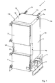
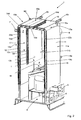
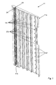
- Fig. 1 to 5 illustrate this an embodiment of a water-conducting biomass boiler 1, which uses pellets as fuel.
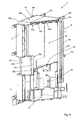
- the wood gasification boiler 1 is shown in a three-dimensional view, while the Fig. 2 to 5 show him in different sectional views.
- the boiler 1 has a connection 5 for the pellet supply and a connection 4 for the primary air supply.
- the pellets enter a lower combustion or wood gasification chamber 19 (FIG. Fig. 5 ) and are burned there or gassed to wood gas.
- a lower combustion or wood gasification chamber 19 Above the lower combustion chamber 19 is an upper combustion chamber 18, in which the resulting during the combustion of the pellets flame is performed together with the smoke and wood gases.
- a space 9 in which an ash box can be arranged to receive combustion residues.
- the flame and the smoke or wood gas pass from the upper combustion chamber 18 into a combustion chamber 16, which is separated by means of a partition 13 from an afterburner 17.
- a partition 13 from an afterburner 17.
- the afterburner 17 combustible components of the flue gas and the wood gas can be burned.
- the partition wall 13 and on the water in the partition wall 13 both the heat from the afterburner 17 and from the combustion chamber 16 is transmitted.
- a flue gas outlet 7 is present, through which the flue gases can be deducted.
- the flue gas outlet 7 is connected to a flue gas inlet 9, which in turn is connected to a chimney connection 8 arranged on the rear side of the boiler 1 ( Fig. 3 ).
- the flue gas outlet 7 is arranged in the second post-combustion chamber, the flame, the hot flue gases and the wood gas are once passed around the partition wall 13 and can deliver their heat to the partition wall 13.
- the combustion chamber 16 together with the post-combustion chamber 17 are accessible via a combustion chamber door 2, while the lower region of the heating boiler 1 with the ash box is accessible through a lower door 3.
- the water-bearing boiler 1 has a plurality of water-carrying wall sections which surround the combustion chamber 16 with the post-combustion chamber 17: an upper wall section 10, a right side wall 11, a left side wall 12, a front wall 20, a rear wall 21 and the partition wall 13.
- These water-carrying wall sections 10-13, 20 and 21 are with several water connections (Water inlets or water returns) 6b, 6c and 6e, 6f connected and are also communicating with each other.
- Two water connections 6b and 6c are arranged on the upper wall section 10 and two water connections 6e and 6f on the rear wall 21. Water can be heated through these water connections 6b, c, e and 6f in a targeted manner through the wall sections 10-13 (connected to one another underwater).
- 20 and 21 circulate, so that the heat generated in the boiler 1 and in particular in the combustion chamber 16 and post-combustion chamber 17 is transmitted as completely as possible to the circulating water.
- each dip tube 6a and 6d On the right side wall 11 and on the left side wall 12 are each a dip tube 6a and 6d in each of which a temperature sensor is arranged to determine the water temperature of the circulating in the side walls 11 and 12 water.
- the outer water-carrying wall sections 10-12, 20 and 21 are all sandwiched. They have an outer wall 10a-12a, 20a and 21a and an inner wall 10b-12b, 20b and 21b.
- the inner walls 10b-12b, 20b and 21b thereby form the inner end walls of the combustion chamber 16 and post-combustion chamber 17, respectively.
- outer walls 10a-12a, 20a and 21a and the inner walls 10b-12b, 20b and 21b are each a plurality of reinforcing elements 14a-e arranged, the respective outer wall 10a-12a, 20a and 21a with the respective inner wall 10b-12b, 20b and 21b of the respective wall section 10-12, 20 and 21 connect.
- the inner walls 10b-12b, 20b and 21b are each made of stainless steel in order to withstand the high temperatures in the combustion chamber 16 and post-combustion chamber 17 can.
- the outer walls 10a-12a, 20a and 21b are made of a less high grade steel grade, in this case ST52 steel, since the outer walls are not exposed to the high temperatures, but only the water temperature of the water inside the respective wall sections. 12, 20a and 21a circulates and the associated water pressure.
- the Partition wall 13 like the other wall sections 10-12, 20 and 21, has a plurality of reinforcing elements 14f connecting the two outer walls 13a and 13b.
- All the reinforcing elements 14a-f of the wall sections 10-13, 20 and 21 respectively have openings 22a-f through which the water in the wall sections 10-13, 20 and 21 can flow.
- the reinforcing elements 14a-f are made of black plate.
- the individual wall sections 10-13, 20 and 21 are communicatively connected to each other (see, for example. Fig. 4 ).
- the rear wall 21, the front wall 20 and the left 12 and right side 13 together with the partition 13 form a continuous cavity through which the water flows.
- the cavity is formed by the respective outer walls 10a-13a, 20a and 21a which are spaced apart from one another and inner walls 10b-12b, 20b and 21b or outer wall 13b of the individual wall sections 10-13, 20 and 21.
- the reinforcing elements 14a-f determine how far the distance is.
- the reinforcing elements 14a-f extend in the standing wall sections 11-13, 20 and 21 from bottom to top respectively through the entire wall section 11-13, 20 and 21.
- the reinforcing elements 14d extend from front to rear
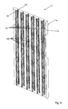
- the left 12 and right 11 side wall and the partition wall 13 each have six equally spaced reinforcing elements 14 a, c and f.
- the upper wall portion 10 and the front wall 20 and the rear wall 21 each have seven equally spaced reinforcing elements 14b, d and e.
- each reinforcing element 14c has a plurality of openings 22 c (fourteen in the present case) can flow through the water in the right wall portion 11.
- Each reinforcing member 14c also has two planar attachment portions 23 and 24 disposed opposite to each other.
- the planar attachment portions 23 and 24 extend over the entire length of the reinforcing member 14c.
- the reinforcing elements 14c is welded to the first fastening section 23 with the outer wall 11a and to the opposite fastening section 24 with the inner wall 11b.
- the reinforcing elements 14c, as well as the other reinforcing elements 14a, b and d-f a Z-shaped profile.
- the two planar mounting portions 23 and 24 form the upper or lower part of the "Z”.
- the middle part of the "Z" form connecting elements 27 which connect the two planar mounting portions 23 and 24 together.
- the spaces between the connecting elements 27 are the openings 22c.
- the wall sections 10-13, 20 and 21 can be made of thin sheet metal.
- the reinforcing elements 14a-f are also uniformly distributed in the respective wall sections 10-13, 20 and 21 so as to reinforce them uniformly and thus to deform the outer walls 10a-13a, 20a and 21a and the inner walls 10b-12b, 20b, 21b, respectively can counteract.
- both the outer walls 10a-13a, 20a, 21a and 13b and the inner walls 10b-12b, 20b and 21b each have a sheet-metal wall thickness of 1.5 mm.
- the reinforcing elements 14a-f are welded by laser welding to the outer walls 10a-13a, 13b, 20a and 21a and inner walls 10b-12, 20b and 21b, respectively.
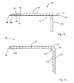
- FIG. 8 and 9 are each two-dimensional cross-sections of a corner joint between the upper wall portion 10 and the rear wall 21 (FIG. Fig. 8 ) or the right side wall 11 (FIG. Fig. 9 ) in which the weld seams are shown and by means of which the welding of the reinforcing elements 14a-f is explained by way of example.
- the Fig. 8 corresponds to a cut, as in Fig. 3 is illustrated and the Fig. 9 a cut, as he eg. in Fig. 2 is illustrated.
- the reinforcing elements 14d of the upper wall section 10 each have one upper planar mounting portion 23a and a lower planar mounting portion 24a, which also respectively represent the upper and lower part of the "Z" profile of the reinforcing member 14d.
- the upper and lower fastening sections 23a, b are connected in each case by a middle connecting element 26, which also forms the middle part of the "Z" -profile of the reinforcing element 14d.
- the upper planar attachment portions 23a are each welded to the outer wall 10a of the upper wall portion 10 by a weld 28a.
- the lower planar attachment portions 24a are each welded to the inner wall wall 10b of the upper wall portion 10 by a weld 28b.
- the weld seams 28a and 28b are each formed by laser welding, in which a laser beam from the outside through the outer wall 10a and from the outside through the inner wall 10b, the outer wall 10a and inner wall 10b has welded to the respective mounting portion 23a and 24a.
- the reinforcing member 14d holds the outer wall 10a and the inner wall 10b together and transmits forces acting on the one wall via the attachment portions 23a and 24a and the connecting member 26 to the other wall.
- the Z-shaped profile of the reinforcing element 14d (or 14a-c and 14e-f) is easy to produce, since it can be easily produced by bending a flat piece of sheet metal twice.
- the Z-profile offers a comparatively high rigidity in terms of both tensile and compressive loads. Due to the symmetrical shape, moreover, the center of gravity is in the center of the "Z", so that a reinforcing element 14d placed on the attachment portion 23a or 24a stops and can be welded therewith without further attachment.
- the rectangular corner joints between wall sections 10-12, 20 and 21 are formed on the outer walls with two angles of 135 ° ( 8 and 9 ).
- transition 15g between the front wall 20 and the right wall section 11 or a transition 15f between the front wall 20 and the left wall section 15f (FIG. Fig. 1 and Fig. 4 ). Also, between the rear wall 21 and the right wall portion 11 such a transition 15d is present and a same transition 15e between the rear wall 21 and the left wall portion 12 is present.
- the inner walls 10b-12b, 20b and 21b are welded to each other at the respective right-angled transitions of the wall sections 10-12, 20 and 21 at the joint.
- the inner wall 21b of the rear wall 21 is connected to the inner wall 10b of the upper wall portion 10 at the right-angled joint with a weld 25a ( Fig. 8 ).
- the inner walls 11b and 10b are connected to a weld 25b (FIG. Fig. 9 ).
- the welds each extend over the entire joint of the inner walls 10-21, 20 and 21 to seal according to the cavity of the associated wall sections 10-12, 20 and 21.
- This weld can be done by conventional welding using a filler material, since the joint is easily accessible.
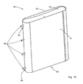
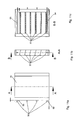
- the buffer memory 50 has a reminiscent of a "hip-flask” form from the outside. He has two outer wall portions 51 and 52 which are arranged opposite to each other. The buffer memory 51 is at its narrow sides (left and right in Fig. 10 ) forms around. The buffer memory 50 is closed at the top and bottom with a lid 53 and bottom 54 watertight. The lid 53 and the bottom 54 are slightly curved inwards ( Fig. 11c ).
- the buffer memory has a number of water and sensor connections 56 on one round side (left side in FIG Fig. 10 ), and two brackets 55 to which the buffer memory 50 can be screwed.
- the lowermost and uppermost water connection 56 extends in each case through the buffer memory 50 from one round end to the other and is fastened in each case for stabilization in the middle with a holder 61 on the lid 53 or bottom 54 (FIG. Fig. 13 ).
- the reinforcing elements 57 connect the two outer wall sections 51 and 52 to each other.
- the reinforcing elements 57 have a Z-shaped profile ( Fig. 13 ). They have two opposite planar mounting portions 58 and 59, which respectively form the upper and lower part of the "Z".
- the first attachment portion 58 is welded to an outer wall portion 52, and the second attachment portion 59 is welded to the opposite outer wall portion 51.
- each reinforcing member 57 has a number of apertures 60 disposed side by side in the direction of the longitudinal direction of the reinforcing member 57 (similar to the apertures 22a-f of the reinforcing members 14a-f of the above-described boiler 1). Through the openings 60, the water stored in the buffer memory 50 can flow therethrough.
- the reinforcing element 57 also has a number of connecting elements 62, which connect the first 58 and second attachment portion 59 together. Between two connecting elements 62, an opening 60 is present in each case.
- the connecting elements 62 which virtually form the middle part of the "Z", are web-like and are formed, for example, when the perforations 60 are punched into the sheet from which the reinforcing elements 57 are produced.
- the buffer memory 50 and the outer wall sections 51 and 52 formed of a stainless steel sheet with a wall thickness of 1 mm. Without reinforcing elements 57, such a buffer memory would deform.
- FIGS. 14 and 15 a manufacturing method for producing a water-carrying wall element 70 made of thin sheet, for example, with a wall thickness of 1.5 mm, described as it comes, for example, in the above-described wall sections 10-13, 20 and 21 or in the buffer memory 50 is used.
- an outer wall element 64 is placed, for example, on a mounting table or a conveyor belt for the production of the wall element 70. Thereafter, a plurality of reinforcing elements 66 are respectively placed at the same distance on the inside 71 of the outer wall member 64.
- the inner side 71 is the side opposite to the outer side 72 with which the outer wall member 64 lies on the mounting table or the conveyor belt.
- each reinforcing element 66 has a Z-shaped profile, as described above in connection with the reinforcing elements 14a-f and 57.
- each reinforcing element 66 has an upper 68 and a lower fastening section 69. Both fastening sections 68 and 69 are planar and serve as a fastening surface on which they are respectively welded to the upper 65 and lower outer wall element 64.
- a connector 67 connects the upper 68 to the lower mounting portion 69, respectively.
- a laser 63 is arranged, which directs a laser beam from below onto the outer side 72 of the outer wall member 64.
- the laser beam has an energy sufficient to melt the material of the outer wall member 64 and the overlying reinforcing member 66 and its attachment portion 68 (or 69).
- the laser 63 thereby welds the outer wall element 64 from the outer side 72 with the reinforcing element 66 arranged on the inner side 71 or with its fastening section 68.
- the laser 63 thereby welds the reinforcing element 66 to the attachment section 68 along its longitudinal orientation, which in FIGS. 14 and 15 perpendicular to the paper plane.
- the laser 63 is perpendicular to the paper plane method.
- the reinforcing element 66 is completely welded to the fastening section 68 with the inner side 71 of the outer wall element 64.
- the resulting weld is continuous and has no interruptions.
- the outer wall member 64 with the reinforcing members 66 thereon is displaced in the direction of the laser 63 along the arrow 66 to the right until the next reinforcing member 66 with its mounting portion 68 is positioned centrally above the laser 63 is and the next weld for the next reinforcing member 66 can be made.
- the upper outer wall member 65 is welded to the reinforcing members 66 in a similar manner as described above.
- the upper outer wall member 65 is placed on the mounting table or the conveyor belt and the outer wall member 64 with the already welded thereon reinforcing members 66 is placed according to the inside of the upper outer wall member 65. Then, the above-described laser welding process is performed analogously for each reinforcing element.
- a continuous outer wall member 65 of the wall member 70 is bent at two spaced locations 74 and 75 in the region of the right angle in each case by 135 °, so that a total of a right angle arise.
- two outer wall elements 64a and 64b are arranged, which each form a leg of the rectangular wall element 70.
- the distance between the two angles 74 and 75 is absent in the two outer wall elements 64a and 64b so that they are at a right angle to each other when the wall element 70 is formed at right angles.
- At the rectangular joint 73 of the two adjacent outer wall elements 64a and 64b they are welded together. This is done by means of a conventional welding process in which filler metals are used.
- the wall element 70 can be made quasi in an endless process and is then, for example, simply tailored to the needs.
- the wall elements 70 can also be produced in a modular manner, so that, for example, a boiler can be easily assembled from the individual wall element modules.
- the present invention is not limited to reinforcing elements with a Z-shaped profile, but any other profiles can be used (for example, C-shaped, double-T-shaped, etc.), which are suitable for connect two opposite outer wall sections together and so to transmit or absorb forces acting on the outer wall sections.
Landscapes
- Engineering & Computer Science (AREA)
- Mechanical Engineering (AREA)
- General Engineering & Computer Science (AREA)
- Chemical & Material Sciences (AREA)
- Combustion & Propulsion (AREA)
- Physics & Mathematics (AREA)
- Thermal Sciences (AREA)
- Heat-Pump Type And Storage Water Heaters (AREA)
- Earth Drilling (AREA)
- Automatic Assembly (AREA)
- Laser Beam Processing (AREA)
Applications Claiming Priority (1)
| Application Number | Priority Date | Filing Date | Title |
|---|---|---|---|
| DE102011008221A DE102011008221B4 (de) | 2011-01-10 | 2011-01-10 | Wasserführender Heizkessel, Pufferspeicher und Verfahren zur Herstellung eines wasserführenden Wandelelements |
Publications (2)
| Publication Number | Publication Date |
|---|---|
| EP2474792A2 true EP2474792A2 (fr) | 2012-07-11 |
| EP2474792A3 EP2474792A3 (fr) | 2012-09-05 |
Family
ID=45497803
Family Applications (1)
| Application Number | Title | Priority Date | Filing Date |
|---|---|---|---|
| EP12000108A Withdrawn EP2474792A3 (fr) | 2011-01-10 | 2012-01-10 | Chaudière transportant de l'eau, accumulateur-tampon et procédé de fabrication d'un élément mural transportant de l'eau |
Country Status (2)
| Country | Link |
|---|---|
| EP (1) | EP2474792A3 (fr) |
| DE (1) | DE102011008221B4 (fr) |
Cited By (2)
| Publication number | Priority date | Publication date | Assignee | Title |
|---|---|---|---|---|
| CN108224764A (zh) * | 2017-12-19 | 2018-06-29 | 刘信玮 | 一种具有异型水箱的节能热水锅炉 |
| CN110017597A (zh) * | 2019-04-15 | 2019-07-16 | 陈雄 | 一种带储水空间的零冷水段热交换器 |
Family Cites Families (17)
| Publication number | Priority date | Publication date | Assignee | Title |
|---|---|---|---|---|
| GB325688A (en) * | 1929-02-14 | 1930-02-27 | Verney Binns | Improvements in and relating to hot water boilers |
| GB531172A (en) * | 1939-03-28 | 1940-12-31 | Leonard Satchwell | Improvements in and relating to boilers |
| US2340431A (en) * | 1942-10-29 | 1944-02-01 | Satchwell Leonard | Boiler |
| US2749887A (en) * | 1955-03-28 | 1956-06-12 | Gustav E Olsen | Welded water wall boiler |
| US4782768A (en) * | 1987-08-24 | 1988-11-08 | Westinghouse Electric Corp. | Rotary combustor with efficient air distribution |
| DE4208958C2 (de) * | 1992-03-19 | 1995-02-16 | Alfons Kruck | Wärmespeicher als Pufferspeicher für eine Raumheizung |
| DE4426097A1 (de) * | 1994-07-22 | 1996-01-25 | Kloeckner Stahl Gmbh | Verfahren zur Herstellung von Hohlkörperstrukturen aus Blechen |
| NL1002215C1 (en) * | 1995-02-01 | 1996-08-01 | Bapro | Storage-vessel production method for solar-energy system |
| DE29721887U1 (de) * | 1997-12-11 | 1998-03-12 | Ratiotherm Heizung + Solartechnik GmbH & Co. KG, 83278 Traunstein | Wärmespeicher als Schichtspeicher |
| EP0962268A1 (fr) * | 1998-06-02 | 1999-12-08 | Solistor B.V. | Procédé de fabrication d'un récipient de sctockage pour stocker un médium et récipient de stockage ainsi fabriqué |
| DE102005055594B4 (de) * | 2005-11-19 | 2016-10-20 | Phoenix Metall Gmbh | Verfahren zur Herstellung einer Heiz-oder Kühlplatte sowie dergestalt hergestellte Heiz-oder Kühlplatte |
| CA2648454C (fr) * | 2008-01-02 | 2016-06-28 | Dunkirk Metal Products, Inc. | Chaudiere a bois ou a matieres de biomasse a rendement eleve |
| AT506594B1 (de) * | 2008-07-10 | 2009-10-15 | Het Heiz & Energietechnik Entw | Verbindungselement |
| DE102008051161B4 (de) * | 2008-10-10 | 2013-05-29 | Highterm Research Gmbh | Wirbelschichtreaktor sowie Einsatz für einen solchen Wirbelschichtreaktor |
| DE202008014878U1 (de) * | 2008-11-10 | 2009-02-19 | Comfort Sinusverteiler Gmbh | Pufferspeicher |
| AT507680B1 (de) * | 2009-02-24 | 2010-07-15 | Ligno Heizsysteme Gmbh | Füllraumauskleidung für brandkessel |
| KR101046784B1 (ko) * | 2009-04-15 | 2011-07-05 | 주식회사 경동나비엔 | 보일러 열교환기의 유로캡 접합방법 |
-
2011
- 2011-01-10 DE DE102011008221A patent/DE102011008221B4/de not_active Expired - Fee Related
-
2012
- 2012-01-10 EP EP12000108A patent/EP2474792A3/fr not_active Withdrawn
Non-Patent Citations (1)
| Title |
|---|
| None |
Cited By (2)
| Publication number | Priority date | Publication date | Assignee | Title |
|---|---|---|---|---|
| CN108224764A (zh) * | 2017-12-19 | 2018-06-29 | 刘信玮 | 一种具有异型水箱的节能热水锅炉 |
| CN110017597A (zh) * | 2019-04-15 | 2019-07-16 | 陈雄 | 一种带储水空间的零冷水段热交换器 |
Also Published As
| Publication number | Publication date |
|---|---|
| DE102011008221A1 (de) | 2012-07-12 |
| EP2474792A3 (fr) | 2012-09-05 |
| DE102011008221B4 (de) | 2013-06-13 |
Similar Documents
| Publication | Publication Date | Title |
|---|---|---|
| DE1911889A1 (de) | Waermeaustauscher | |
| DE3043887A1 (de) | Heizkessel insbesondere fuer zentralheizungen | |
| DE102011008221B4 (de) | Wasserführender Heizkessel, Pufferspeicher und Verfahren zur Herstellung eines wasserführenden Wandelelements | |
| DE2820832B2 (de) | Wasserrohrkessel für eine Sammelheizungsanlage | |
| DE4301804C1 (de) | Gas-Wandheizkessel | |
| EP0473982A2 (fr) | Pierre de manteau de cheminée pour cheminées domestiques | |
| EP0281125B1 (fr) | Chaudière à éléments | |
| EP0706010B1 (fr) | Appareil de chauffage avec arrangement de buses | |
| DE1909126C3 (de) | Verfahren zum Herstellen einer Heizgastasche für einen Heizungskessel ' | |
| DE3205120C2 (de) | Wandausbildung für Heizungskessel zum Verbrennen flüssiger oder gasförmiger Brennstoffe | |
| EP0120435A2 (fr) | Structure du parcours du gaz de chauffage dans une chaudière de chauffage | |
| DE2919471A1 (de) | Offener kamin | |
| DE2911020B1 (de) | Stahlheizungskessel | |
| EP0430061B1 (fr) | Chaudière de chauffage | |
| DE45169C (de) | Dampfkessel mit Längsflanschen | |
| DE2331571A1 (de) | Kessel, insbesondere fuer zentralheizungszwecke | |
| AT43509B (de) | Gliederkessel. | |
| DE2025472C3 (de) | Heizungskessel | |
| DE3048007A1 (de) | Umgebungsluft-waermeaustauscher | |
| DE167334C (fr) | ||
| DE2557569A1 (de) | Heizkessel zum erhitzen von fluessigkeiten | |
| DE363375C (de) | Schmiedeeiserner Gliederkessel aus hufeisenfoermig gebogenen Rohren mit angeschweissten Rohren zur Bildung der Heizkanaele | |
| EP3290795B1 (fr) | Chaudière | |
| DE181525C (fr) | ||
| DE161685C (fr) |
Legal Events
| Date | Code | Title | Description |
|---|---|---|---|
| PUAI | Public reference made under article 153(3) epc to a published international application that has entered the european phase |
Free format text: ORIGINAL CODE: 0009012 |
|
| AK | Designated contracting states |
Kind code of ref document: A2 Designated state(s): AL AT BE BG CH CY CZ DE DK EE ES FI FR GB GR HR HU IE IS IT LI LT LU LV MC MK MT NL NO PL PT RO RS SE SI SK SM TR |
|
| AX | Request for extension of the european patent |
Extension state: BA ME |
|
| PUAL | Search report despatched |
Free format text: ORIGINAL CODE: 0009013 |
|
| AK | Designated contracting states |
Kind code of ref document: A3 Designated state(s): AL AT BE BG CH CY CZ DE DK EE ES FI FR GB GR HR HU IE IS IT LI LT LU LV MC MK MT NL NO PL PT RO RS SE SI SK SM TR |
|
| AX | Request for extension of the european patent |
Extension state: BA ME |
|
| RIC1 | Information provided on ipc code assigned before grant |
Ipc: F24H 1/00 20060101AFI20120731BHEP Ipc: F24H 1/18 20060101ALI20120731BHEP Ipc: F28D 20/00 20060101ALI20120731BHEP Ipc: B21D 26/059 20110101ALI20120731BHEP Ipc: F24B 1/02 20060101ALI20120731BHEP Ipc: F24H 1/26 20060101ALI20120731BHEP Ipc: F24H 9/00 20060101ALI20120731BHEP |
|
| 17P | Request for examination filed |
Effective date: 20130301 |
|
| STAA | Information on the status of an ep patent application or granted ep patent |
Free format text: STATUS: THE APPLICATION IS DEEMED TO BE WITHDRAWN |
|
| 18D | Application deemed to be withdrawn |
Effective date: 20150801 |