EP2474759B1 - Twin clutch type hybrid transmission - Google Patents
Twin clutch type hybrid transmission Download PDFInfo
- Publication number
- EP2474759B1 EP2474759B1 EP10813567.4A EP10813567A EP2474759B1 EP 2474759 B1 EP2474759 B1 EP 2474759B1 EP 10813567 A EP10813567 A EP 10813567A EP 2474759 B1 EP2474759 B1 EP 2474759B1
- Authority
- EP
- European Patent Office
- Prior art keywords
- numbered stage
- odd
- motor
- gear train
- clutch
- Prior art date
- Legal status (The legal status is an assumption and is not a legal conclusion. Google has not performed a legal analysis and makes no representation as to the accuracy of the status listed.)
- Active
Links
- 230000005540 biological transmission Effects 0.000 title claims description 327
- 230000007246 mechanism Effects 0.000 claims description 105
- 230000008929 regeneration Effects 0.000 claims description 21
- 238000011069 regeneration method Methods 0.000 claims description 21
- 230000001172 regenerating effect Effects 0.000 claims description 16
- 230000001133 acceleration Effects 0.000 claims description 11
- 230000003213 activating effect Effects 0.000 claims description 4
- 238000010586 diagram Methods 0.000 description 27
- 238000002360 preparation method Methods 0.000 description 26
- 230000004048 modification Effects 0.000 description 10
- 238000012986 modification Methods 0.000 description 10
- 238000005381 potential energy Methods 0.000 description 3
- 230000009471 action Effects 0.000 description 2
- 230000015556 catabolic process Effects 0.000 description 2
- 230000000694 effects Effects 0.000 description 2
- 230000006870 function Effects 0.000 description 2
- 238000010237 hybrid technique Methods 0.000 description 2
- 230000007935 neutral effect Effects 0.000 description 2
- 238000011084 recovery Methods 0.000 description 2
- 230000004044 response Effects 0.000 description 2
- 238000005549 size reduction Methods 0.000 description 2
- 230000004913 activation Effects 0.000 description 1
- 238000006243 chemical reaction Methods 0.000 description 1
- 238000010276 construction Methods 0.000 description 1
- 238000001816 cooling Methods 0.000 description 1
- 230000001419 dependent effect Effects 0.000 description 1
- 238000011161 development Methods 0.000 description 1
- 230000018109 developmental process Effects 0.000 description 1
- 230000005611 electricity Effects 0.000 description 1
- 230000002708 enhancing effect Effects 0.000 description 1
- 239000012530 fluid Substances 0.000 description 1
- 239000000446 fuel Substances 0.000 description 1
- 238000000034 method Methods 0.000 description 1
- 230000009467 reduction Effects 0.000 description 1
- 239000007858 starting material Substances 0.000 description 1
Images


Classifications
-
- F—MECHANICAL ENGINEERING; LIGHTING; HEATING; WEAPONS; BLASTING
- F16—ENGINEERING ELEMENTS AND UNITS; GENERAL MEASURES FOR PRODUCING AND MAINTAINING EFFECTIVE FUNCTIONING OF MACHINES OR INSTALLATIONS; THERMAL INSULATION IN GENERAL
- F16H—GEARING
- F16H3/00—Toothed gearings for conveying rotary motion with variable gear ratio or for reversing rotary motion
- F16H3/006—Toothed gearings for conveying rotary motion with variable gear ratio or for reversing rotary motion power being selectively transmitted by either one of the parallel flow paths
-
- B—PERFORMING OPERATIONS; TRANSPORTING
- B60—VEHICLES IN GENERAL
- B60K—ARRANGEMENT OR MOUNTING OF PROPULSION UNITS OR OF TRANSMISSIONS IN VEHICLES; ARRANGEMENT OR MOUNTING OF PLURAL DIVERSE PRIME-MOVERS IN VEHICLES; AUXILIARY DRIVES FOR VEHICLES; INSTRUMENTATION OR DASHBOARDS FOR VEHICLES; ARRANGEMENTS IN CONNECTION WITH COOLING, AIR INTAKE, GAS EXHAUST OR FUEL SUPPLY OF PROPULSION UNITS IN VEHICLES
- B60K6/00—Arrangement or mounting of plural diverse prime-movers for mutual or common propulsion, e.g. hybrid propulsion systems comprising electric motors and internal combustion engines ; Control systems therefor, i.e. systems controlling two or more prime movers, or controlling one of these prime movers and any of the transmission, drive or drive units Informative references: mechanical gearings with secondary electric drive F16H3/72; arrangements for handling mechanical energy structurally associated with the dynamo-electric machine H02K7/00; machines comprising structurally interrelated motor and generator parts H02K51/00; dynamo-electric machines not otherwise provided for in H02K see H02K99/00
- B60K6/20—Arrangement or mounting of plural diverse prime-movers for mutual or common propulsion, e.g. hybrid propulsion systems comprising electric motors and internal combustion engines ; Control systems therefor, i.e. systems controlling two or more prime movers, or controlling one of these prime movers and any of the transmission, drive or drive units Informative references: mechanical gearings with secondary electric drive F16H3/72; arrangements for handling mechanical energy structurally associated with the dynamo-electric machine H02K7/00; machines comprising structurally interrelated motor and generator parts H02K51/00; dynamo-electric machines not otherwise provided for in H02K see H02K99/00 the prime-movers consisting of electric motors and internal combustion engines, e.g. HEVs
- B60K6/42—Arrangement or mounting of plural diverse prime-movers for mutual or common propulsion, e.g. hybrid propulsion systems comprising electric motors and internal combustion engines ; Control systems therefor, i.e. systems controlling two or more prime movers, or controlling one of these prime movers and any of the transmission, drive or drive units Informative references: mechanical gearings with secondary electric drive F16H3/72; arrangements for handling mechanical energy structurally associated with the dynamo-electric machine H02K7/00; machines comprising structurally interrelated motor and generator parts H02K51/00; dynamo-electric machines not otherwise provided for in H02K see H02K99/00 the prime-movers consisting of electric motors and internal combustion engines, e.g. HEVs characterised by the architecture of the hybrid electric vehicle
- B60K6/44—Series-parallel type
- B60K6/442—Series-parallel switching type
-
- B—PERFORMING OPERATIONS; TRANSPORTING
- B60—VEHICLES IN GENERAL
- B60K—ARRANGEMENT OR MOUNTING OF PROPULSION UNITS OR OF TRANSMISSIONS IN VEHICLES; ARRANGEMENT OR MOUNTING OF PLURAL DIVERSE PRIME-MOVERS IN VEHICLES; AUXILIARY DRIVES FOR VEHICLES; INSTRUMENTATION OR DASHBOARDS FOR VEHICLES; ARRANGEMENTS IN CONNECTION WITH COOLING, AIR INTAKE, GAS EXHAUST OR FUEL SUPPLY OF PROPULSION UNITS IN VEHICLES
- B60K6/00—Arrangement or mounting of plural diverse prime-movers for mutual or common propulsion, e.g. hybrid propulsion systems comprising electric motors and internal combustion engines ; Control systems therefor, i.e. systems controlling two or more prime movers, or controlling one of these prime movers and any of the transmission, drive or drive units Informative references: mechanical gearings with secondary electric drive F16H3/72; arrangements for handling mechanical energy structurally associated with the dynamo-electric machine H02K7/00; machines comprising structurally interrelated motor and generator parts H02K51/00; dynamo-electric machines not otherwise provided for in H02K see H02K99/00
- B60K6/20—Arrangement or mounting of plural diverse prime-movers for mutual or common propulsion, e.g. hybrid propulsion systems comprising electric motors and internal combustion engines ; Control systems therefor, i.e. systems controlling two or more prime movers, or controlling one of these prime movers and any of the transmission, drive or drive units Informative references: mechanical gearings with secondary electric drive F16H3/72; arrangements for handling mechanical energy structurally associated with the dynamo-electric machine H02K7/00; machines comprising structurally interrelated motor and generator parts H02K51/00; dynamo-electric machines not otherwise provided for in H02K see H02K99/00 the prime-movers consisting of electric motors and internal combustion engines, e.g. HEVs
- B60K6/42—Arrangement or mounting of plural diverse prime-movers for mutual or common propulsion, e.g. hybrid propulsion systems comprising electric motors and internal combustion engines ; Control systems therefor, i.e. systems controlling two or more prime movers, or controlling one of these prime movers and any of the transmission, drive or drive units Informative references: mechanical gearings with secondary electric drive F16H3/72; arrangements for handling mechanical energy structurally associated with the dynamo-electric machine H02K7/00; machines comprising structurally interrelated motor and generator parts H02K51/00; dynamo-electric machines not otherwise provided for in H02K see H02K99/00 the prime-movers consisting of electric motors and internal combustion engines, e.g. HEVs characterised by the architecture of the hybrid electric vehicle
- B60K6/48—Parallel type
-
- B—PERFORMING OPERATIONS; TRANSPORTING
- B60—VEHICLES IN GENERAL
- B60K—ARRANGEMENT OR MOUNTING OF PROPULSION UNITS OR OF TRANSMISSIONS IN VEHICLES; ARRANGEMENT OR MOUNTING OF PLURAL DIVERSE PRIME-MOVERS IN VEHICLES; AUXILIARY DRIVES FOR VEHICLES; INSTRUMENTATION OR DASHBOARDS FOR VEHICLES; ARRANGEMENTS IN CONNECTION WITH COOLING, AIR INTAKE, GAS EXHAUST OR FUEL SUPPLY OF PROPULSION UNITS IN VEHICLES
- B60K6/00—Arrangement or mounting of plural diverse prime-movers for mutual or common propulsion, e.g. hybrid propulsion systems comprising electric motors and internal combustion engines ; Control systems therefor, i.e. systems controlling two or more prime movers, or controlling one of these prime movers and any of the transmission, drive or drive units Informative references: mechanical gearings with secondary electric drive F16H3/72; arrangements for handling mechanical energy structurally associated with the dynamo-electric machine H02K7/00; machines comprising structurally interrelated motor and generator parts H02K51/00; dynamo-electric machines not otherwise provided for in H02K see H02K99/00
- B60K6/20—Arrangement or mounting of plural diverse prime-movers for mutual or common propulsion, e.g. hybrid propulsion systems comprising electric motors and internal combustion engines ; Control systems therefor, i.e. systems controlling two or more prime movers, or controlling one of these prime movers and any of the transmission, drive or drive units Informative references: mechanical gearings with secondary electric drive F16H3/72; arrangements for handling mechanical energy structurally associated with the dynamo-electric machine H02K7/00; machines comprising structurally interrelated motor and generator parts H02K51/00; dynamo-electric machines not otherwise provided for in H02K see H02K99/00 the prime-movers consisting of electric motors and internal combustion engines, e.g. HEVs
- B60K6/50—Architecture of the driveline characterised by arrangement or kind of transmission units
- B60K6/54—Transmission for changing ratio
- B60K6/547—Transmission for changing ratio the transmission being a stepped gearing
-
- B—PERFORMING OPERATIONS; TRANSPORTING
- B60—VEHICLES IN GENERAL
- B60L—PROPULSION OF ELECTRICALLY-PROPELLED VEHICLES; SUPPLYING ELECTRIC POWER FOR AUXILIARY EQUIPMENT OF ELECTRICALLY-PROPELLED VEHICLES; ELECTRODYNAMIC BRAKE SYSTEMS FOR VEHICLES IN GENERAL; MAGNETIC SUSPENSION OR LEVITATION FOR VEHICLES; MONITORING OPERATING VARIABLES OF ELECTRICALLY-PROPELLED VEHICLES; ELECTRIC SAFETY DEVICES FOR ELECTRICALLY-PROPELLED VEHICLES
- B60L15/00—Methods, circuits, or devices for controlling the traction-motor speed of electrically-propelled vehicles
- B60L15/20—Methods, circuits, or devices for controlling the traction-motor speed of electrically-propelled vehicles for control of the vehicle or its driving motor to achieve a desired performance, e.g. speed, torque, programmed variation of speed
-
- B—PERFORMING OPERATIONS; TRANSPORTING
- B60—VEHICLES IN GENERAL
- B60L—PROPULSION OF ELECTRICALLY-PROPELLED VEHICLES; SUPPLYING ELECTRIC POWER FOR AUXILIARY EQUIPMENT OF ELECTRICALLY-PROPELLED VEHICLES; ELECTRODYNAMIC BRAKE SYSTEMS FOR VEHICLES IN GENERAL; MAGNETIC SUSPENSION OR LEVITATION FOR VEHICLES; MONITORING OPERATING VARIABLES OF ELECTRICALLY-PROPELLED VEHICLES; ELECTRIC SAFETY DEVICES FOR ELECTRICALLY-PROPELLED VEHICLES
- B60L50/00—Electric propulsion with power supplied within the vehicle
- B60L50/10—Electric propulsion with power supplied within the vehicle using propulsion power supplied by engine-driven generators, e.g. generators driven by combustion engines
- B60L50/16—Electric propulsion with power supplied within the vehicle using propulsion power supplied by engine-driven generators, e.g. generators driven by combustion engines with provision for separate direct mechanical propulsion
-
- B—PERFORMING OPERATIONS; TRANSPORTING
- B60—VEHICLES IN GENERAL
- B60L—PROPULSION OF ELECTRICALLY-PROPELLED VEHICLES; SUPPLYING ELECTRIC POWER FOR AUXILIARY EQUIPMENT OF ELECTRICALLY-PROPELLED VEHICLES; ELECTRODYNAMIC BRAKE SYSTEMS FOR VEHICLES IN GENERAL; MAGNETIC SUSPENSION OR LEVITATION FOR VEHICLES; MONITORING OPERATING VARIABLES OF ELECTRICALLY-PROPELLED VEHICLES; ELECTRIC SAFETY DEVICES FOR ELECTRICALLY-PROPELLED VEHICLES
- B60L7/00—Electrodynamic brake systems for vehicles in general
- B60L7/10—Dynamic electric regenerative braking
- B60L7/14—Dynamic electric regenerative braking for vehicles propelled by ac motors
-
- B—PERFORMING OPERATIONS; TRANSPORTING
- B60—VEHICLES IN GENERAL
- B60W—CONJOINT CONTROL OF VEHICLE SUB-UNITS OF DIFFERENT TYPE OR DIFFERENT FUNCTION; CONTROL SYSTEMS SPECIALLY ADAPTED FOR HYBRID VEHICLES; ROAD VEHICLE DRIVE CONTROL SYSTEMS FOR PURPOSES NOT RELATED TO THE CONTROL OF A PARTICULAR SUB-UNIT
- B60W10/00—Conjoint control of vehicle sub-units of different type or different function
- B60W10/10—Conjoint control of vehicle sub-units of different type or different function including control of change-speed gearings
- B60W10/11—Stepped gearings
- B60W10/113—Stepped gearings with two input flow paths, e.g. double clutch transmission selection of one of the torque flow paths by the corresponding input clutch
-
- B—PERFORMING OPERATIONS; TRANSPORTING
- B60—VEHICLES IN GENERAL
- B60K—ARRANGEMENT OR MOUNTING OF PROPULSION UNITS OR OF TRANSMISSIONS IN VEHICLES; ARRANGEMENT OR MOUNTING OF PLURAL DIVERSE PRIME-MOVERS IN VEHICLES; AUXILIARY DRIVES FOR VEHICLES; INSTRUMENTATION OR DASHBOARDS FOR VEHICLES; ARRANGEMENTS IN CONNECTION WITH COOLING, AIR INTAKE, GAS EXHAUST OR FUEL SUPPLY OF PROPULSION UNITS IN VEHICLES
- B60K6/00—Arrangement or mounting of plural diverse prime-movers for mutual or common propulsion, e.g. hybrid propulsion systems comprising electric motors and internal combustion engines ; Control systems therefor, i.e. systems controlling two or more prime movers, or controlling one of these prime movers and any of the transmission, drive or drive units Informative references: mechanical gearings with secondary electric drive F16H3/72; arrangements for handling mechanical energy structurally associated with the dynamo-electric machine H02K7/00; machines comprising structurally interrelated motor and generator parts H02K51/00; dynamo-electric machines not otherwise provided for in H02K see H02K99/00
- B60K6/20—Arrangement or mounting of plural diverse prime-movers for mutual or common propulsion, e.g. hybrid propulsion systems comprising electric motors and internal combustion engines ; Control systems therefor, i.e. systems controlling two or more prime movers, or controlling one of these prime movers and any of the transmission, drive or drive units Informative references: mechanical gearings with secondary electric drive F16H3/72; arrangements for handling mechanical energy structurally associated with the dynamo-electric machine H02K7/00; machines comprising structurally interrelated motor and generator parts H02K51/00; dynamo-electric machines not otherwise provided for in H02K see H02K99/00 the prime-movers consisting of electric motors and internal combustion engines, e.g. HEVs
- B60K6/42—Arrangement or mounting of plural diverse prime-movers for mutual or common propulsion, e.g. hybrid propulsion systems comprising electric motors and internal combustion engines ; Control systems therefor, i.e. systems controlling two or more prime movers, or controlling one of these prime movers and any of the transmission, drive or drive units Informative references: mechanical gearings with secondary electric drive F16H3/72; arrangements for handling mechanical energy structurally associated with the dynamo-electric machine H02K7/00; machines comprising structurally interrelated motor and generator parts H02K51/00; dynamo-electric machines not otherwise provided for in H02K see H02K99/00 the prime-movers consisting of electric motors and internal combustion engines, e.g. HEVs characterised by the architecture of the hybrid electric vehicle
- B60K6/48—Parallel type
- B60K2006/4825—Electric machine connected or connectable to gearbox input shaft
-
- B—PERFORMING OPERATIONS; TRANSPORTING
- B60—VEHICLES IN GENERAL
- B60L—PROPULSION OF ELECTRICALLY-PROPELLED VEHICLES; SUPPLYING ELECTRIC POWER FOR AUXILIARY EQUIPMENT OF ELECTRICALLY-PROPELLED VEHICLES; ELECTRODYNAMIC BRAKE SYSTEMS FOR VEHICLES IN GENERAL; MAGNETIC SUSPENSION OR LEVITATION FOR VEHICLES; MONITORING OPERATING VARIABLES OF ELECTRICALLY-PROPELLED VEHICLES; ELECTRIC SAFETY DEVICES FOR ELECTRICALLY-PROPELLED VEHICLES
- B60L2200/00—Type of vehicles
- B60L2200/26—Rail vehicles
-
- B—PERFORMING OPERATIONS; TRANSPORTING
- B60—VEHICLES IN GENERAL
- B60L—PROPULSION OF ELECTRICALLY-PROPELLED VEHICLES; SUPPLYING ELECTRIC POWER FOR AUXILIARY EQUIPMENT OF ELECTRICALLY-PROPELLED VEHICLES; ELECTRODYNAMIC BRAKE SYSTEMS FOR VEHICLES IN GENERAL; MAGNETIC SUSPENSION OR LEVITATION FOR VEHICLES; MONITORING OPERATING VARIABLES OF ELECTRICALLY-PROPELLED VEHICLES; ELECTRIC SAFETY DEVICES FOR ELECTRICALLY-PROPELLED VEHICLES
- B60L2210/00—Converter types
- B60L2210/40—DC to AC converters
-
- B—PERFORMING OPERATIONS; TRANSPORTING
- B60—VEHICLES IN GENERAL
- B60L—PROPULSION OF ELECTRICALLY-PROPELLED VEHICLES; SUPPLYING ELECTRIC POWER FOR AUXILIARY EQUIPMENT OF ELECTRICALLY-PROPELLED VEHICLES; ELECTRODYNAMIC BRAKE SYSTEMS FOR VEHICLES IN GENERAL; MAGNETIC SUSPENSION OR LEVITATION FOR VEHICLES; MONITORING OPERATING VARIABLES OF ELECTRICALLY-PROPELLED VEHICLES; ELECTRIC SAFETY DEVICES FOR ELECTRICALLY-PROPELLED VEHICLES
- B60L2240/00—Control parameters of input or output; Target parameters
- B60L2240/40—Drive Train control parameters
- B60L2240/42—Drive Train control parameters related to electric machines
- B60L2240/423—Torque
-
- B—PERFORMING OPERATIONS; TRANSPORTING
- B60—VEHICLES IN GENERAL
- B60L—PROPULSION OF ELECTRICALLY-PROPELLED VEHICLES; SUPPLYING ELECTRIC POWER FOR AUXILIARY EQUIPMENT OF ELECTRICALLY-PROPELLED VEHICLES; ELECTRODYNAMIC BRAKE SYSTEMS FOR VEHICLES IN GENERAL; MAGNETIC SUSPENSION OR LEVITATION FOR VEHICLES; MONITORING OPERATING VARIABLES OF ELECTRICALLY-PROPELLED VEHICLES; ELECTRIC SAFETY DEVICES FOR ELECTRICALLY-PROPELLED VEHICLES
- B60L2240/00—Control parameters of input or output; Target parameters
- B60L2240/40—Drive Train control parameters
- B60L2240/44—Drive Train control parameters related to combustion engines
- B60L2240/443—Torque
-
- B—PERFORMING OPERATIONS; TRANSPORTING
- B60—VEHICLES IN GENERAL
- B60L—PROPULSION OF ELECTRICALLY-PROPELLED VEHICLES; SUPPLYING ELECTRIC POWER FOR AUXILIARY EQUIPMENT OF ELECTRICALLY-PROPELLED VEHICLES; ELECTRODYNAMIC BRAKE SYSTEMS FOR VEHICLES IN GENERAL; MAGNETIC SUSPENSION OR LEVITATION FOR VEHICLES; MONITORING OPERATING VARIABLES OF ELECTRICALLY-PROPELLED VEHICLES; ELECTRIC SAFETY DEVICES FOR ELECTRICALLY-PROPELLED VEHICLES
- B60L2240/00—Control parameters of input or output; Target parameters
- B60L2240/40—Drive Train control parameters
- B60L2240/50—Drive Train control parameters related to clutches
- B60L2240/507—Operating parameters
-
- B—PERFORMING OPERATIONS; TRANSPORTING
- B60—VEHICLES IN GENERAL
- B60L—PROPULSION OF ELECTRICALLY-PROPELLED VEHICLES; SUPPLYING ELECTRIC POWER FOR AUXILIARY EQUIPMENT OF ELECTRICALLY-PROPELLED VEHICLES; ELECTRODYNAMIC BRAKE SYSTEMS FOR VEHICLES IN GENERAL; MAGNETIC SUSPENSION OR LEVITATION FOR VEHICLES; MONITORING OPERATING VARIABLES OF ELECTRICALLY-PROPELLED VEHICLES; ELECTRIC SAFETY DEVICES FOR ELECTRICALLY-PROPELLED VEHICLES
- B60L2270/00—Problem solutions or means not otherwise provided for
- B60L2270/10—Emission reduction
- B60L2270/14—Emission reduction of noise
- B60L2270/145—Structure borne vibrations
-
- B—PERFORMING OPERATIONS; TRANSPORTING
- B60—VEHICLES IN GENERAL
- B60W—CONJOINT CONTROL OF VEHICLE SUB-UNITS OF DIFFERENT TYPE OR DIFFERENT FUNCTION; CONTROL SYSTEMS SPECIALLY ADAPTED FOR HYBRID VEHICLES; ROAD VEHICLE DRIVE CONTROL SYSTEMS FOR PURPOSES NOT RELATED TO THE CONTROL OF A PARTICULAR SUB-UNIT
- B60W30/00—Purposes of road vehicle drive control systems not related to the control of a particular sub-unit, e.g. of systems using conjoint control of vehicle sub-units, or advanced driver assistance systems for ensuring comfort, stability and safety or drive control systems for propelling or retarding the vehicle
- B60W30/18—Propelling the vehicle
- B60W30/19—Improvement of gear change, e.g. by synchronisation or smoothing gear shift
-
- B—PERFORMING OPERATIONS; TRANSPORTING
- B60—VEHICLES IN GENERAL
- B60Y—INDEXING SCHEME RELATING TO ASPECTS CROSS-CUTTING VEHICLE TECHNOLOGY
- B60Y2400/00—Special features of vehicle units
- B60Y2400/42—Clutches or brakes
- B60Y2400/428—Double clutch arrangements; Dual clutches
-
- F—MECHANICAL ENGINEERING; LIGHTING; HEATING; WEAPONS; BLASTING
- F16—ENGINEERING ELEMENTS AND UNITS; GENERAL MEASURES FOR PRODUCING AND MAINTAINING EFFECTIVE FUNCTIONING OF MACHINES OR INSTALLATIONS; THERMAL INSULATION IN GENERAL
- F16H—GEARING
- F16H2200/00—Transmissions for multiple ratios
- F16H2200/003—Transmissions for multiple ratios characterised by the number of forward speeds
- F16H2200/006—Transmissions for multiple ratios characterised by the number of forward speeds the gear ratios comprising eight forward speeds
-
- F—MECHANICAL ENGINEERING; LIGHTING; HEATING; WEAPONS; BLASTING
- F16—ENGINEERING ELEMENTS AND UNITS; GENERAL MEASURES FOR PRODUCING AND MAINTAINING EFFECTIVE FUNCTIONING OF MACHINES OR INSTALLATIONS; THERMAL INSULATION IN GENERAL
- F16H—GEARING
- F16H3/00—Toothed gearings for conveying rotary motion with variable gear ratio or for reversing rotary motion
- F16H3/02—Toothed gearings for conveying rotary motion with variable gear ratio or for reversing rotary motion without gears having orbital motion
- F16H3/08—Toothed gearings for conveying rotary motion with variable gear ratio or for reversing rotary motion without gears having orbital motion exclusively or essentially with continuously meshing gears, that can be disengaged from their shafts
- F16H3/087—Toothed gearings for conveying rotary motion with variable gear ratio or for reversing rotary motion without gears having orbital motion exclusively or essentially with continuously meshing gears, that can be disengaged from their shafts characterised by the disposition of the gears
- F16H3/093—Toothed gearings for conveying rotary motion with variable gear ratio or for reversing rotary motion without gears having orbital motion exclusively or essentially with continuously meshing gears, that can be disengaged from their shafts characterised by the disposition of the gears with two or more countershafts
- F16H3/097—Toothed gearings for conveying rotary motion with variable gear ratio or for reversing rotary motion without gears having orbital motion exclusively or essentially with continuously meshing gears, that can be disengaged from their shafts characterised by the disposition of the gears with two or more countershafts the input and output shafts being aligned on the same axis
-
- Y—GENERAL TAGGING OF NEW TECHNOLOGICAL DEVELOPMENTS; GENERAL TAGGING OF CROSS-SECTIONAL TECHNOLOGIES SPANNING OVER SEVERAL SECTIONS OF THE IPC; TECHNICAL SUBJECTS COVERED BY FORMER USPC CROSS-REFERENCE ART COLLECTIONS [XRACs] AND DIGESTS
- Y02—TECHNOLOGIES OR APPLICATIONS FOR MITIGATION OR ADAPTATION AGAINST CLIMATE CHANGE
- Y02T—CLIMATE CHANGE MITIGATION TECHNOLOGIES RELATED TO TRANSPORTATION
- Y02T10/00—Road transport of goods or passengers
- Y02T10/60—Other road transportation technologies with climate change mitigation effect
- Y02T10/62—Hybrid vehicles
-
- Y—GENERAL TAGGING OF NEW TECHNOLOGICAL DEVELOPMENTS; GENERAL TAGGING OF CROSS-SECTIONAL TECHNOLOGIES SPANNING OVER SEVERAL SECTIONS OF THE IPC; TECHNICAL SUBJECTS COVERED BY FORMER USPC CROSS-REFERENCE ART COLLECTIONS [XRACs] AND DIGESTS
- Y02—TECHNOLOGIES OR APPLICATIONS FOR MITIGATION OR ADAPTATION AGAINST CLIMATE CHANGE
- Y02T—CLIMATE CHANGE MITIGATION TECHNOLOGIES RELATED TO TRANSPORTATION
- Y02T10/00—Road transport of goods or passengers
- Y02T10/60—Other road transportation technologies with climate change mitigation effect
- Y02T10/64—Electric machine technologies in electromobility
-
- Y—GENERAL TAGGING OF NEW TECHNOLOGICAL DEVELOPMENTS; GENERAL TAGGING OF CROSS-SECTIONAL TECHNOLOGIES SPANNING OVER SEVERAL SECTIONS OF THE IPC; TECHNICAL SUBJECTS COVERED BY FORMER USPC CROSS-REFERENCE ART COLLECTIONS [XRACs] AND DIGESTS
- Y02—TECHNOLOGIES OR APPLICATIONS FOR MITIGATION OR ADAPTATION AGAINST CLIMATE CHANGE
- Y02T—CLIMATE CHANGE MITIGATION TECHNOLOGIES RELATED TO TRANSPORTATION
- Y02T10/00—Road transport of goods or passengers
- Y02T10/60—Other road transportation technologies with climate change mitigation effect
- Y02T10/70—Energy storage systems for electromobility, e.g. batteries
-
- Y—GENERAL TAGGING OF NEW TECHNOLOGICAL DEVELOPMENTS; GENERAL TAGGING OF CROSS-SECTIONAL TECHNOLOGIES SPANNING OVER SEVERAL SECTIONS OF THE IPC; TECHNICAL SUBJECTS COVERED BY FORMER USPC CROSS-REFERENCE ART COLLECTIONS [XRACs] AND DIGESTS
- Y02—TECHNOLOGIES OR APPLICATIONS FOR MITIGATION OR ADAPTATION AGAINST CLIMATE CHANGE
- Y02T—CLIMATE CHANGE MITIGATION TECHNOLOGIES RELATED TO TRANSPORTATION
- Y02T10/00—Road transport of goods or passengers
- Y02T10/60—Other road transportation technologies with climate change mitigation effect
- Y02T10/7072—Electromobility specific charging systems or methods for batteries, ultracapacitors, supercapacitors or double-layer capacitors
-
- Y—GENERAL TAGGING OF NEW TECHNOLOGICAL DEVELOPMENTS; GENERAL TAGGING OF CROSS-SECTIONAL TECHNOLOGIES SPANNING OVER SEVERAL SECTIONS OF THE IPC; TECHNICAL SUBJECTS COVERED BY FORMER USPC CROSS-REFERENCE ART COLLECTIONS [XRACs] AND DIGESTS
- Y02—TECHNOLOGIES OR APPLICATIONS FOR MITIGATION OR ADAPTATION AGAINST CLIMATE CHANGE
- Y02T—CLIMATE CHANGE MITIGATION TECHNOLOGIES RELATED TO TRANSPORTATION
- Y02T10/00—Road transport of goods or passengers
- Y02T10/60—Other road transportation technologies with climate change mitigation effect
- Y02T10/72—Electric energy management in electromobility
-
- Y—GENERAL TAGGING OF NEW TECHNOLOGICAL DEVELOPMENTS; GENERAL TAGGING OF CROSS-SECTIONAL TECHNOLOGIES SPANNING OVER SEVERAL SECTIONS OF THE IPC; TECHNICAL SUBJECTS COVERED BY FORMER USPC CROSS-REFERENCE ART COLLECTIONS [XRACs] AND DIGESTS
- Y10—TECHNICAL SUBJECTS COVERED BY FORMER USPC
- Y10T—TECHNICAL SUBJECTS COVERED BY FORMER US CLASSIFICATION
- Y10T74/00—Machine element or mechanism
- Y10T74/19—Gearing
- Y10T74/19023—Plural power paths to and/or from gearing
- Y10T74/19051—Single driven plural drives
Definitions
- the present invention relates to a twin-clutch type transmission that performs control of gear shift by using two or more clutches in combination, and more specifically, to a hybrid technique using a motor in combination.
- Conventionally used transmissions for diesel railcars include a torque converter for transmitting the power of an engine, multi-stage shift gears connected to the torque converter, and a wet type multiple disc clutch for switching the shift gears (see the publication of Registered Japanese Utility Model Application 2565596 ).
- a technique employed in transmissions for diesel railcars for enhancing transmission efficiency by using a mechanical clutch in place of the wet type multiple disc clutch is also suggested (see the publication of Japanese Utility Model Application Laid-Open No. Hei. 2-103555 , and the publication of Japanese Patent Application Laid-Open No. Hei. 1-220761 ).
- a twin-clutch type transmission for use in automobiles has been put into practical use in recent years (see publication of Japanese Patent Application Laid-Open No. 2003-269592 , and Mitsubishi Motors Technical Review 2008 No. 20, pp. 31-34 ). Such a twin-clutch type transmission has already been used as a transmission for racing cars.
- a motor is provided in addition to an engine for assisting power with the motor during start or acceleration, and to generate electricity with the motor during deceleration.
- Transmissions for large dump trucks or diesel railcars obtain pulling power in a low vehicle speed range by using power transmission through a torque converter in consideration of the output characteristics of an engine.
- the torque converter generally results in low transmission efficiency as the power is transmitted through a fluid. Accordingly, these transmissions suffer from further reduction of transmission efficiency as a result of longer time of operation with the torque converter.
- twin-clutch type transmissions are particularly likely to increase their overall lengths by the length of a clutch. If these twin-clutch type transmissions are used in a large dump truck, for example, a high-capacity torque converter should be disposed in a former stage, resulting in a problem of further increase of the lengths of the transmissions.
- twin-clutch type transmissions require a synchronization clutch in each stage in order to provide synchronization during upshift or downshift. If a wet type multiple disc clutch is used as a synchronization clutch, and if the number of shift stages is increased to enhance the transmission efficiency of the transmissions, the number of wet type multiple disc clutches placed in corresponding stages is increased. A disengaged wet type multiple disc clutch (not involved in power transmission) idles, generating a problem of idling loss. In particular, if the aforementioned twin-clutch type transmissions are used for large dump trucks or diesel railcars, the capacity of a wet type multiple disc clutch should be increased, resulting in a problem of further increase of idling loss.
- Such idling loss generated by a wet type multiple disc clutch may be prevented by using a mechanical clutch such as that disclosed in the publication of Utility Model Application Laid-Open No. 2-103555 or publication of Japanese Patent Application Laid-Open No. 1-220761 listed above.
- a mechanical clutch such as that disclosed in the publication of Utility Model Application Laid-Open No. 2-103555 or publication of Japanese Patent Application Laid-Open No. 1-220761 listed above.
- the structure of a transmission for automobiles generally includes a synchromesh, and accordingly, such a transmission cannot be used directly in transmitting high power, high torque and high inertia required in large dump trucks and others.
- US 2002/088288 A1 discloses a twin-clutch type hybrid mechanism according to the preamble of claim 1.
- a further twin-clutch type hybrid mechanism is known from US 2002/189397 A1 .
- the present invention has been made in view of the aforementioned problems. It is an object of the invention to provide a more compact twin-clutch type transmission having higher efficiency by combining a motor with the twinclutch type transmission.
- the object of the invention is achieved with a twin-clutch type hybrid mechanism having the features of the preamble of claim 1.
- an excellent effect can be achieved as the invention can provide a highly efficient twin-clutch type hybrid transmission having a compact and simple structure and capable of making prompt gear shift.
- a twin-clutch type hybrid transmission (hereinafter called a transmission) of embodiments of the present invention will be described below by referring to the drawings.
- the transmission is used preferably in a large dump truck and others.
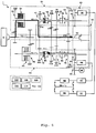
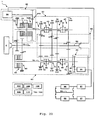
- Fig. 1 shows the structure of a transmission 1 of a first embodiment of the present invention.
- the transmission 1 includes: an input shaft 10 to receive the power of a diesel engine 2; an odd-numbered stage shift mechanism 30 to which the rotation of the input shaft 10 is transmitted; an even-numbered stage shift mechanism 60 to which the rotation of the input shaft 10 is also transmitted; a motor power mechanism 20 for applying the power of a motor to the odd-numbered stage shift mechanism 30 and the even-numbered stage shift mechanism 60; an output mechanism 90 to which the power of the odd-numbered stage shift mechanism 30 and the power of the even-numbered stage shift mechanism 60 are selectively transmitted; and a transmission control unit (TCU) 100 for controlling gear shift action.
- the odd-numbered stage shift mechanism 30 is responsible for gear shift between first, third, fifth, and seventh speeds.
- the even-numbered stage shift mechanism 60 is responsible for gear shift between second, fourth, sixth, and eighth speeds. Accordingly, the transmission 1 can make gear shift between eight stages in total.
- the odd-numbered stage shift mechanism 30 and the even-numbered stage shift mechanism 60 are each provided with a clutch. Accordingly, while power is transmitted in the odd-numbered stage shift mechanism 30, for example, preparations for shift-up or shift-down to an adjacent stage can be made in the even-numbered stage shift mechanism 60. In addition, while power is transmitted in the even-numbered stage shift mechanism 60, preparations for shift-up or shift-down to an adjacent stage can be made in the odd-numbered stage shift mechanism 30.
- the odd-numbered stage shift mechanism 30 includes: an odd-numbered stage transmission gear train 32 for transmitting the rotation of the input shaft 10; an odd-numbered stage main clutch 34 for selectively transmitting the power of the odd-numbered stage transmission gear train 32 to an odd-numbered stage transmission shaft 40; first to seventh (first, third, fifth, and seventh) odd-numbered stage shift gear trains 41, 43, 45 and 47 provided to the odd-numbered stage transmission shaft 40, for transmitting rotation in four stages to the output mechanism 90; and odd-numbered stage mechanical clutches 50 and 52 for selectively engaging the first to seventh (first, third, fifth, and seventh) odd-numbered stage shift gear trains 41, 43, 45 and 47 and the odd-numbered stage transmission shaft 40.
- the odd-numbered stage transmission gear train 32 is composed of a shift gear pair providing the number of input teeth of 21, the number of output teeth of 42, and a ratio of rotation of 2.000.
- the odd-numbered stage transmission gear train 32 is provided between the input shaft 10 and the odd-numbered stage main clutch 34.
- the odd-numbered stage transmission gear train 32 decelerates the rotation of the input shaft 10, and transmits the rotation to the odd-numbered stage main clutch 34.
- the odd-numbered stage main clutch 34 is a wet type multiple disc clutch, and can selectively transmit the rotation of the input shaft 10 to the odd-numbered stage transmission shaft 40 by using hydraulic pressure.
- the odd-numbered stage shift mechanism 30 selectively transmits the rotation of the input shaft 10 to the odd-numbered stage transmission shaft 40 at a ratio of rotation of 2.000 by using the odd-numbered stage main clutch 34.
- the first-speed shift gear train 41 provided to the odd-numbered stage transmission shaft 40 is composed of a shift gear pair with the number of input teeth of 20, the number of output teeth of 42, and a ratio of rotation of 2.100.
- the first-shift gear train 41 transmits the rotation of the odd-numbered stage transmission shaft 40 to an output shaft 92 of the output mechanism 90.
- the third-speed shift gear train 43 is composed of a shift gear pair with the number of input teeth of 34, the number of output teeth of 43, and a ratio of rotation of 1.265.
- the third-speed shift gear train 43 transmits the rotation of the odd-numbered stage transmission shaft 40 to the output shaft 92 of the output mechanism 90.
- the fifth-speed shift gear train 45 is composed of a shift gear pair with the number of input teeth of 44, the number of output teeth of 43, and a ratio of rotation of 0.773.
- the fifth-speed shift gear train 45 transmits the rotation of the odd-numbered stage transmission shaft 40 to the output shaft 92 of the output mechanism 90.
- the seventh-speed shift gear train 47 is composed of a shift gear pair with the number of input teeth of 53, the number of output teeth of 25, and a ratio of rotation of 0.472.
- the seventh-speed shift gear train 47 transmits the rotation of the odd-numbered stage transmission shaft 40 to the output shaft 92 of the output mechanism 90.
- the odd-numbered stage mechanical clutch 50 is placed between the first-speed shift gear train 41 and the third-speed shift gear train 43.
- the odd-numbered stage mechanical clutch 50 can selectively switch among a "first speed engaged condition" where the first-speed shift gear train 41 and the odd-numbered stage transmission shaft 40 are engaged, a "third speed engaged condition” where the third-speed shift gear train 43 and the odd-numbered stage transmission shaft 40 are engaged, and a "disengaged condition" where both the first-speed and third-speed shift gear trains 41 and 43 are disengaged from the odd-numbered stage transmission shaft 40.
- the other odd-numbered stage mechanical clutch 52 is placed between the fifth-speed shift gear train 45 and the seventh-speed shift gear train 47.
- the odd-numbered stage mechanical clutch 52 can selectively switch among a "fifth speed engaged condition" where the fifth-speed shift gear train 45 and the odd-numbered stage transmission shaft 40 are engaged, a "seventh speed engaged condition” where the seventh-speed shift gear train 47 and the odd-numbered stage transmission shaft 40 are engaged, and a "disengaged condition" where both the fifth-speed and seventh-speed shift gear trains 45 and 47 are disengaged from the odd-numbered stage transmission shaft 40.
- selection among the first, third, fifth and seventh speeds, and neutral can be made where appropriate by switching the odd-numbered stage mechanical clutch 50 or 52 appropriately.
- the output mechanism 90 includes the output shaft 92.
- the power of the output shaft 92 is transmitted to wheels through a propeller shaft, a differential gear and the like not specifically shown in the drawings.
- the even-numbered stage shift mechanism 60 includes: an even-numbered stage transmission gear train 62 for transmitting the rotation of the input shaft 10; an even-numbered stage main clutch 64 for selectively transmitting the power of the even-numbered stage transmission gear train 62 to an even-numbered stage transmission shaft 70; second to eighth (second, fourth, sixth, and eighth) even-numbered stage shift gear trains 72, 74, 76 and 78 provided to the even-numbered stage transmission shaft 70, for transmitting rotation in four stages to the output mechanism 90; and even-numbered stage mechanical clutches 80 and 82 for selectively engaging the second to eighth (second, fourth, sixth, and eighth) even-numbered stage shift gear trains 72, 74, 76 and 78 and the even-numbered stage transmission shaft 70.
- the even-numbered stage transmission gear train 62 is composed of a shift gear pair with the number of input teeth of 30, the number of output teeth of 47, and a ratio of rotation of 1.567.
- the even-numbered stage transmission gear train 62 is provided between the input shaft 10 and the even-numbered stage main clutch 64.
- the even-numbered stage transmission gear train 62 decelerates the rotation of the input shaft 10, and transmits the rotation to the even-numbered stage main clutch 64.
- the even-numbered stage main clutch 64 is a wet type multiple disc clutch, and can selectively transmit the rotation of the input shaft 10 to the even-numbered stage transmission shaft 70.
- the even-numbered stage shift mechanism 60 selectively transmits the rotation of the input shaft 10 to the even-numbered stage transmission shaft 70 at a ratio of rotation of 1.567 by using the even-numbered stage main clutch 64.
- the second-speed shift gear train 72 provided to the even-numbered stage transmission shaft 70 is composed of a shift gear pair with the number of input teeth of 20, the number of output teeth of 42, and a ratio of rotation of 2.100.
- the second-speed shift gear train 72 transmits the rotation of the even-numbered stage transmission shaft 70 to the output shaft 92 of the output mechanism 90.
- An output gear of this shift gear pair is shared with the shift gear pair of the first-speed shift gear train 41 of the odd-numbered stage shift mechanism 30.
- the second-speed shift gear train 72 and the first-speed shift gear train 41 have substantially the same (here, completely the same) ratio of rotation.
- the shift gears used for the second-speed shift gear train 72 and those used for the first-speed shift gear train 41 are actually completely the same.
- a ratio between a ratio of rotation between input and output of the first-speed and that between input and output of the second-speed agrees with a ratio between the ratio of rotation of the odd-numbered stage transmission gear train 32 and that of the even-numbered stage transmission gear train 62.
- the fourth-speed shift gear train 74 is composed of a shift gear pair with the number of input teeth of 34, the number of output teeth of 43, and a ratio of rotation of 1.265.
- the fourth-speed shift gear train 74 transmits the rotation of the even-numbered stage transmission shaft 70 to the output shaft 92 of the output mechanism 90.
- An output gear of this shift gear pair is shared with the shift gear pair of the third-speed shift gear train 43 of the odd-numbered stage shift mechanism 30.
- the fourth-speed shift gear train 74 and the third-speed shift gear train 43 have substantially the same (here, completely the same) ratio of rotation. Accordingly, in the present embodiment, the shift gears used for the fourth-speed shift gear train 74 and those used for the third-speed shift gear train 43 are completely the same.
- an interstage ratio between a ratio of rotation between input and output of the third-speed and that between input and output of the fourth-speed agrees with a ratio between the ratio of rotation of the odd-numbered stage transmission gear train 32 and that of the even-numbered stage transmission gear train 62.
- the sixth-speed shift gear train 76 is composed of a shift gear pair with the number of input teeth of 44, the number of output teeth of 34, and a ratio of rotation of 0.773.
- the sixth-speed shift gear train 76 transmits the rotation of the even-numbered stage transmission shaft 70 to the output shaft 92 of the output mechanism 90.
- An output gear of this shift gear pair is shared with the shift gear pair of the fifth-speed shift gear train 45 of the odd-numbered stage shift mechanism 30.
- the sixth-speed shift gear train 76 and the fifth-speed shift gear train 45 also have substantially the same (here, completely the same) ratio of rotation. Accordingly, in the present embodiment, the shift gears used for the sixth-speed shift gear train 76 and those used for the fifth-speed shift gear train 45 are completely the same.
- an interstage ratio between a ratio of rotation between input and output of the fifth speed and that between input and output of the sixth speed agrees with a ratio between the ratio of rotation of the odd-numbered stage transmission gear train 32 and that of the even-numbered stage transmission gear train 62.
- the eighth-speed shift gear train 78 is composed of a shift gear pair with the number of input teeth of 53, the number of output teeth of 25, and a ratio of rotation of 0.472.
- the eighth-speed shift gear train 78 transmits the rotation of the even-numbered stage transmission shaft 70 to the output shaft 92 of the output mechanism 90.
- An output gear of this shift gear pair is shared with the shift gear pair of the seventh-speed shift gear train 47 of the odd-numbered stage shift mechanism 30.
- the eighth-speed shift gear train 78 and the seventh-speed shift gear train 47 have substantially the same (here, completely the same) ratio of rotation. Accordingly, in the present embodiment, the shift gears used for the eighth-speed shift gear train 78 and those used for the seventh-speed shift gear train 47 are completely the same.
- an interstage ratio between a ratio of rotation between input and output of the seventh speed and that between input and output of the eighth speed agrees with a ratio between the ratio of rotation of the odd-numbered stage transmission gear train 32 and that of the even-numbered stage transmission gear train 62.
- the even-numbered stage mechanical clutch 80 is placed between the second-speed shift gear train 72 and the fourth-speed shift gear train 74.
- the even-numbered stage mechanical clutch 80 can selectively switch among a "second speed engaged condition" where the second-speed shift gear train 72 and the even-numbered stage transmission shaft 70 are engaged, a "fourth speed engaged condition” where the fourth-speed shift gear train 74 and the even-numbered stage transmission shaft 70 are engaged, and a "disengaged condition" where both the second-speed and fourth-speed shift gear trains 72 and 74 are disengaged from the even-numbered stage transmission shaft 70.
- the even-numbered stage mechanical clutch 82 is placed between the sixth-speed shift gear train 76 and the eighth-speed shift gear train 78.
- the even-numbered stage mechanical clutch 82 can selectively switch among a "sixth speed engaged condition" where the sixth-speed shift gear train 76 and the even-numbered stage transmission shaft 70 are engaged, an "eight speed engaged condition” where the eighth-speed shift gear train 78 and the even-numbered stage transmission shaft 70 are engaged, and a "disengaged condition" where both the sixth-speed and eighth-speed shift gear trains 76 and 78 are disengaged from the even-numbered stage transmission shaft 70.
- selection among the second, fourth, sixth and eighth speeds, and neutral can be made where appropriate by switching the even-numbered stage mechanical clutch 80 or 82 appropriately.
- the motor power mechanism 20 includes a gear train 54 for an odd-numbered stage motor and provided at an end portion of the odd-numbered stage transmission shaft 40, and an odd-numbered stage motor 56 connected to the gear train 54 for an odd-numbered stage motor.
- An odd-numbered stage inverter 57 and an odd-numbered stage battery 58 are connected to the odd-numbered stage motor 56.
- the odd-numbered stage motor 56 causes the odd-numbered stage transmission shaft 40 to rotate through the gear train 54 for an odd-numbered stage motor.
- This provides synchronization of the rotation of the odd-numbered stage transmission shaft 40 with the rotation of any one of the first to seventh (first, third, fifth, and seventh) odd-numbered stage shift gear trains 41, 43, 45 and 47, thereby engaging the odd-numbered stage mechanical clutch 50 or 52.
- shift-up or shift-down to a target odd-numbered stage is realized.
- the rotation of the odd-numbered stage transmission shaft 40 is transmitted through the gear train 54 for an odd-numbered stage motor to the odd-numbered stage motor 56.
- the motor power mechanism 20 further includes a gear train 84 for an even-numbered stage motor and provided at an end portion of the even-numbered stage transmission shaft 70, and an even-numbered stage motor 86 connected to the gear train 84 for an even-numbered stage motor.
- An even-numbered stage inverter 87 and an even-numbered stage battery 88 are connected to the even-numbered stage motor 86.
- the even-numbered stage battery 88 and the odd-numbered stage battery 58 are connected in series in normal times. However, on the assumption of breakdown of either battery, for example, a cutoff path 89 is provided by which the broken battery is disconnected from a power supply circuit involved.
- the even-numbered stage motor 86 causes the even-numbered stage transmission shaft 70 to rotate through the gear train 84 for an even-numbered stage motor. This provides synchronization of the rotation of the even-numbered stage transmission shaft 70 with any one of the second to eighth (second, fourth, sixth, and eighth) even-numbered stage shift gear trains 72, 74, 76 and 78, thereby engaging the even-numbered stage mechanical clutch 80 or 82. To be specific, shift-up or shift-down to a target even-numbered stage is realized. During regeneration, the rotation of the even-numbered stage transmission shaft 70 is transmitted through the gear train 84 for an even-numbered stage motor to the even-numbered stage motor 86.
- the even-numbered stage motor 86 of the motor power mechanism 20 is also connected through a gear train 96 for external transmission to an actuator 98 for external work.
- a working hydraulic pump is used as the actuator 98 for external work.
- the actuator 98 for external work is driven by the power of the even-numbered stage motor 86.
- the actuator 98 for external work is used to tilt a loading platform and to put a crane into operation, for example.
- the actuator 98 for external work is driven with the even-numbered stage motor 86. This allows performance of external work while an engine is stopped, so that the work can be conducted quietly during nighttime hours, for example.
- the even-numbered stage motor 86 may be driven by a hydraulic motor in order to take a load off a loading platform or a crane. This allows regeneration of potential energy.
- Ratios of rotation of the first to eighth speeds obtained in the transmission 1 with the aforementioned structure are shown in the table given below.
- the gear shift action of the transmission 1 will be described next by giving a description of the transmission control unit 100. It is assumed that the input shaft 10 is caused to rotate at 1000 min -1 if the transmission 1 is driven by the diesel engine 2.
- the transmission control unit 100 includes various sensors, a CPU, a memory, and a power supply unit not specifically shown in the drawings.
- the transmission control unit 100 further includes various sensors such as a clutch sensor 102 for detecting the condition of each clutch, an output-side rotation sensor 104 capable of directly or indirectly detecting the numbers of rotations of the first to seventh (first, third, fifth, and seventh) odd-numbered stage shift gear trains 41, 43, 45 and 47 and the number of rotations of the second to eighth (second, fourth, sixth, and eighth) even-numbered stage shift gear trains 72, 74, 76 and 78, and an input-side rotation sensor 106 capable of directly or indirectly detecting the number of rotations of the input shaft 10 (the number of rotations of the engine 2).
- the transmission control unit 100 also includes a clutch actuator 110 for putting each clutch of the transmission 1 into operation, a motor controller 114 for controlling a motor, and others.
- the transmission control unit 100 controls the transmission 1 in response to execution of a predetermined program stored in the memory by the CPU.
- the functional structures of the transmission control unit 100 include an odd-numbered stage synchronization controller 120, an even-numbered stage synchronization controller 122, a start controller 124, a switching controller 126, a deceleration controller 128, an assist controller 130, a regeneration controller 132, an emergency start controller 134, and a shift controller 136.
- Each of the functional structures will be described by referring to Fig. 3 and its subsequent drawings.
- the start controller 124 engages the odd-numbered stage mechanical clutch 50 to make the "first speed engaged condition,” and at the same time, engages the even-numbered stage mechanical clutch 80 to make the "second speed engaged condition.”
- the odd-numbered stage motor 56 and the even-numbered stage motor 86 are thereafter caused to rotate at the same time.
- the power of the odd-numbered stage motor 56 and the power of the even-numbered stage motor 86 are both transmitted to the output shaft 92, allowing high-torque drive with the two motors. This eliminates the need for start with the engine 2.
- the switching controller 126 starts the engine 2 as shown in Fig. 4 .
- the engine 2 can be started by letting the engine 2 run from the output side while the odd-numbered stage main clutch 34 is put in a halfway engaged condition, making operation of a starter for the engine 2 unnecessary. After the engine is started, the odd-numbered stage main clutch 34 is engaged gradually while the odd-numbered stage main clutch 34 in a halfway engaged condition is caused to slip. As a result, the power of the engine 2 is transmitted through the input shaft 10 and the odd-numbered stage transmission gear train 32 to the odd-numbered stage transmission shaft 40.
- the odd-numbered stage transmission shaft is caused to rotate at approximately 500 min -1 .
- the rotation of the odd-numbered stage transmission shaft 40 is transmitted through the first-speed shift gear train 41 to the output shaft 92, thereby causing the output shaft 92 to rotate at 238.1 min -1 .
- drive of the odd-numbered stage motor 56 and the even-numbered stage motor 86 is stopped to release the even-numbered stage mechanical clutch 80, thereby realizing the "disengaged condition.”
- the input gear of the second-speed shift gear train 72 (shift gear closer to the even-numbered stage transmission shaft 70) of the even-numbered stage shift mechanism 60 rotates at about 500 min -1 .
- the even-numbered stage synchronization controller 122 drives the even-numbered stage motor 86 to control the rotation of the even-numbered stage transmission shaft 70 at about 500 min -1 as shown in Fig. 5 .
- This provides synchronization of the rotation of the even-numbered stage transmission shaft 70 and the rotation of the second-speed shift gear train 72 to engage the even-numbered stage mechanical clutch 80, thereby making the "second speed engaged condition.” Accordingly, preparations for shift-up to the second speed are completed, and drive of the even-numbered stage motor 86 is stopped.
- the shift controller 136 engages the even-numbered stage main clutch 64 gradually as shown in Fig. 6 .
- the shift controller 136 brings the odd-numbered stage main clutch 34 into the "disengaged condition" to prevent transmission of the rotation of the odd-numbered stage transmission shaft 40 to the output shaft 92.
- This increases the rotation of the engine to 1000 min -1 , increases the rotation of the even-numbered stage transmission shaft 70 from 500 min -1 to 638 min -1 , and increases the rotation of the output shaft 92 to 304 min -1 .
- shift-up to the second speed is completed.
- the odd-numbered stage mechanical clutch 50 is brought into the "disengaged condition" to make preparations for a next shift.
- the input gear of the third-speed shift gear train 43 (shift gear closer to the odd-numbered stage transmission shaft 40) of the odd-numbered stage shift mechanism 30 rotates at about 384 min -1 determined by the ratio of rotation thereof.
- the odd-numbered stage synchronization controller 120 drives the odd-numbered stage motor 56 to control the rotation of the odd-numbered stage transmission shaft 40 at about 384 min -1 as shown in Fig. 7 .
- This provides synchronization of the rotation of the odd-numbered stage transmission shaft 40 and the rotation of the third-speed shift gear train 43 to engage the odd-numbered stage mechanical clutch 50, thereby making the "third speed engaged condition.” Accordingly, preparations for shift-up to the third speed are completed, and drive of the odd-numbered stage motor 56 is stopped.
- the shift controller 136 engages the odd-numbered stage main clutch 34 gradually as shown in Fig. 8 .
- the shift controller 136 brings the even-numbered stage main clutch 64 into the "disengaged condition" to prevent transmission of the rotation of the even-numbered stage transmission shaft 70 to the output shaft 92.
- This increases the rotation of the engine to 1000 min -1 , increases the rotation of the odd-numbered stage transmission shaft 40 from 384 min -1 to 500 min -1 , and increases the rotation of the output shaft 92 to 395 min -1 .
- shift-up to the third speed is completed.
- the even-numbered stage mechanical clutch 80 is brought into the "disengaged condition" to make preparations for a next shift. Shift-up to the fourth speed and shift-up to its subsequent speeds are performed in the same manner, and they will not be described here.
- the second-speed shift gear train 72 is engaged with the even-numbered stage transmission shaft 70. More specifically, the output shaft 92 rotates at 395 min -1 during the operation at the third speed. Accordingly, the gear of the second-speed shift gear train 72 in the even-numbered stage shift mechanism 60 closer to the even-numbered stage transmission shaft 70 rotates at 830 min -1 .
- the even-numbered stage synchronization controller 122 drives the even-numbered stage motor 86 to increase the rotation of the even-numbered stage transmission shaft 70 to 830 min -1 as shown in Fig. 9 .
- the shift controller 136 engages the even-numbered stage main clutch 64 gradually as shown in Fig. 10 .
- the shift controller 136 brings the odd-numbered stage main clutch 34 into the "disengaged condition" to prevent transmission of the rotation of the odd-numbered stage transmission shaft 40 to the output shaft 92.
- This reduces the rotation of the engine to 1000 min -1 , reduces the rotation of the even-numbered stage transmission shaft 70 from 830 min -1 to 638 min -1 , and reduces the rotation of the output shaft 92 to 304 min -1 .
- shift-down to the second speed is completed.
- the odd-numbered stage mechanical clutch 50 is brought into the "disengaged condition" to make preparations for a next shift.
- the first-speed shift gear train 41 is engaged with the odd-numbered stage transmission shaft 40. More specifically, the output shaft 92 rotates at 304 min -1 during the operation at the second speed. Accordingly, the shift gear of the first-speed shift gear train 41 in the odd-numbered stage shift mechanism 30 closer to the odd-numbered stage transmission shaft 40 rotates at 638 min -1 .
- the odd-numbered stage synchronization controller 120 drives the odd-numbered stage motor 56 to increase the rotation of the odd-numbered stage transmission shaft 40 to 638 min -1 as shown in Fig. 11 .
- the shift controller 136 engages the odd-numbered stage main clutch 34 gradually as shown in Fig. 12 .
- the shift controller 136 brings the even-numbered stage main clutch 64 into the "disengaged condition" to prevent transmission of the rotation of the even-numbered stage transmission shaft 70 to the output shaft 92.
- This reduces the rotation of the engine to 1000 min -1 , reduces the rotation of the odd-numbered stage transmission shaft 40 from 638 min -1 to 500 min -1 , and reduces the rotation of the output shaft 92 to 238 min -1 .
- shift-down to the first speed is completed.
- the even-numbered stage mechanical clutch 80 is brought into the "disengaged condition" to make preparations for a next shift.
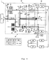
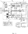
- the deceleration controller 128 makes engagement of any one of the odd-numbered stages by using the odd-numbered stage mechanical clutch 50 or 52 in addition to engagement of the even-numbered stage mechanical clutch 80 as shown in Fig. 13 .
- the number of a stage to be engaged can be selected freely from the first, third, fifth and seventh speeds. However, it is preferable that a stage in a low number (such as the first speed) be engaged in order to enhance the efficiency of a regenerative brake.
- the odd-numbered stage synchronization controller 120 temporarily drives the odd-numbered stage motor 56 to provide synchronization.
- the "first speed engaged condition" is made.
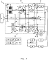
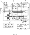
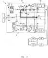
- the assist controller 130 drives the even-numbered stage motor 86 to assist power as shown in Fig. 14 . This compensates for the torque of the engine 2 to allow rapid acceleration.
- power assist by the odd-numbered stage motor 56 can be added by making engagement of any one of the odd-numbered stages by using the odd-numbered stage mechanical clutch 50 or 52 in addition to engagement of the even-numbered stage mechanical clutch 80.
- the regeneration controller 132 brings any one of the odd-numbered stages into the "engaged condition" by using the odd-numbered stage mechanical clutch 50 or 52 in the odd-numbered stage shift mechanism 30, and transmits the redundant power of the engine 2 to the odd-numbered stage motor 56 to regenerate the transmitted power, thereby charging the batteries 58 and 88.
- a stage to be engaged with the odd-numbered stage mechanical clutch for the purpose of regeneration can be selected freely from the first, third, fifth and seventh speeds.
- a stage of a low number (such as the first speed) be engaged in order to enhance the efficiency of the regenerative brake.
- the odd-numbered stage synchronization controller 120 temporarily drives the odd-numbered stage motor 56 to provide synchronization.
- the "first speed engaged condition" is made to increase the number of rotations of the odd-numbered stage motor 56 to enhance regeneration efficiency.
- a stage of an optimum number may be selected and then engaged appropriately according to running condition.
- the even-numbered stage shift mechanism 60 may be responsible for regeneration.
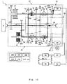
- the emergency start controller 134 starts the engine 2, releases the odd-numbered stage main clutch 34, and engages the even-numbered stage main clutch 64 as shown in Fig. 16 .
- the even-numbered stage motor 86 is caused to rotate by the power of the engine 2 transmitted through the even-numbered stage transmission shaft 70, thereby charging the batteries 58 and 88.
- the "first speed engaged condition" is made by the odd-numbered stage mechanical clutch 50.
- the odd-numbered stage motor 56 is caused to rotate by using the batteries 58 and 88 being charged to realize emergency start.
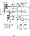
- the odd-numbered stage mechanical clutch 50 may be engaged to make the "first speed engaged condition," and at the same time, the even-numbered stage mechanical clutch 80 may be engaged to make the "second speed engaged condition" as shown in Fig. 17 . Then, while both the odd-numbered stage main clutch 34 and the even-numbered stage main clutch 64 in a halfway condition are caused to slip, the power of the engine 2 may be transmitted to the output shaft 92, thereby making start. Departure of a dump truck and the like requires transmission of commensurate torque. Meanwhile, using both the odd-numbered stage main clutch 34 and the even-numbered stage main clutch 64 at the same time can reduce a load to be placed on each of the main clutches 34 and 64 by half, thereby realizing compact sizes of the main clutches 34 and 64.
- the motor power mechanism 20 includes the odd-numbered stage motor 56 for the odd-numbered stages and the even-numbered stage motor 86 for the even-numbered stages. This realizes synchronization control of the mechanical clutches with the motors 56 and 86. As a result, a synchromesh or a wet type multiple disc clutch dedicated to synchronization becomes unnecessary. Further, synchronization promptly made by the motors 56 and 86 realizes prompt shift-up and shift-down. Using the two motors 56 and 86 also allows size reduction of each of the motors.
- substantially complete synchronization is realized by the motors, allowing the mechanical clutches to engage the transmission shafts 40 and 70 and corresponding shift gear trains. Idling loss generated by the mechanical clutches during a disengaged condition is remarkably smaller than that generated by a wet type multiple disc clutch, so that transmission efficiency determined during operation is enhanced considerably.
- the transmission 1 high-torque operation for start (backward motion) is allowed by using the motors 56 and 86 effectively. This eliminates the need to provide the engine 2 with a torque converter. Accordingly, transmission loss by a torque converter during low-speed operation will not occur, making it possible to enhance transmission efficiency. Even if lockup is achieved during high-speed operation, use of a torque converter generates internal loss due to collision of oil in the converter with an impeller. However, the transmission 1 does not require a torque converter in the first place, making it possible to enhance transmission efficiency during high-speed operation. In addition, the transmission 1 includes wet type multiple disc clutches only at two places (as the main clutches 34 and 64).
- the transmission 1 makes one of the odd-numbered stage and even-numbered stage shift mechanisms 30 and 60 charge the batteries 58 and 88 by using the power of the engine 2, and makes the other of the odd-numbered stage and even-numbered stage shift mechanisms 30 and 60 to make start with a motor. Accordingly, these features unique to the twin-clutch type are reasonably used to allow reliable operation for start.
- the transmission 1 can assist the power of the engine 2 by using the motors 56 and 86, making it possible to enhance acceleration performance. For example, shortage of torque of the engine 2 to be generated during uphill move and the like can be compensated for by assistance with the motors 56 and 86. As a result, the capacity of the engine 2 can be reduced.
- the transmission 1 makes the two motors 56 and 86 activate the regenerative brake, allowing efficient recovery of energy.
- the transmission 1 can also make the two motors 56 and 86 regenerate the redundant energy of the engine 2 efficiently during stable running at the seventh or eighth speed, making it possible to enhance fuel efficiency.
- the transmission 1 can continue running with one of the batteries in the case of breakdown of the other battery. Even if both the batteries 58 and 88 are broken, the engine 2 realizes start while the main clutches 34 and 64 are each placed in a halfway engaged condition, meaning that the transmission 1 can respond to an emergency flexibly.
- the transmission 1 can operate the actuator 98 for external work using the motors 56 and 86. Accordingly, work to be conducted while vehicle is stopped is driven electrically, making it possible to reduce noise during the work. For example, in order to bring a loading platform or a crane up with a hydraulic motor during nighttime hours, for example, use of a motor as a driving source allows work to be performed quietly. In order to bring the loading platform or the crane down, the potential energy thereof is transmitted through the hydraulic motor to the motors 56 and 88, thereby allowing regeneration of the potential energy.
- adjacent shift gear trains such as the first-speed shift gear train 41 and the second-speed shift gear train 72 have substantially the same gear ratio. This allows the first-speed shift gear train 41 and the second-speed shift gear train 72 to use the same shift gears, or to share the shift gear of the output shaft 92.
- the transmission 1 has an eight-stage structure, sharing of a shift gear makes the size in the directions of the shafts be substantially a level corresponding to four stages, allowing significant size reduction of the transmission 1.
- the transmission 1 may also be of a structure placing high priority to a speed ratio in which a shift gear is not shared.
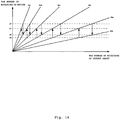
- the ratio of rotation of the even-numbered stage transmission shaft 70 to the rotation of odd-numbered stage transmission shaft 40 is substantially the same as the interstage ratio of 1.289.
- shift gear trains in adjacent shift stages such as the first-speed shift gear train 41 and the second-speed shift gear train 72 can have substantially the same gear ratio as described above.
- the reason therefor is that a target interstage ratio can be maintained by the ratio of rotation of the odd-numbered stage transmission gear train 32 and that of the even-numbered stage transmission gear train 62 (corresponding to the interstage ratio).
- a ratio between the gear ratio of the second-speed shift gear train 72 and that of the third-speed shift gear train 43 is set at a value (1.66) corresponding substantially to the square of the interstage ratio (1.289).
- synchronization between the first odd-numbered stage shift gear train 41 and the second even-numbered stage shift gear train 72 during upshift or downshift therebetween can be made by causing the odd-numbered stage transmission shaft 40 and the even-numbered stage transmission shaft 70 to rotate at the same speed.
- This also applies to the cases between the third odd-numbered stage shift gear train 43 and the fourth even-numbered stage shift gear train 74, between the fifth odd-numbered stage shift gear train 45 and the sixth even-numbered stage shift gear train 76, and between the seventh odd-numbered stage shift gear train 47 and the eighth even-numbered stage shift gear train 78.
- synchronization between the second even-numbered stage shift gear train 72 and the third odd-numbered stage shift gear train 43 during upshift or downshift therebetween can be made by causing the odd-numbered stage transmission shaft 40 and even-numbered stage transmission shaft 70 to rotate at a ratio corresponding to a value that is close to the square of the interstage ratio. This also applies to the cases between the fourth even-numbered stage shift gear train 74 and the fifth odd-numbered stage shift gear train 45, and between the sixth even-numbered stage shift gear train 76 and the seventh odd-numbered stage shift gear train 47.
- the odd-numbered stage transmission shaft 40 and the even-numbered stage transmission shaft 70 are allowed to rotate at substantially the constant speeds of rotation in all the speed stages during upshift and downshift as shown in Fig. 18 .
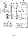
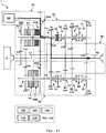
- Fig. 19 shows a modification of the transmission 1 of the first embodiment.
- the odd-numbered stage motor 56 and the even-numbered stage motor 86 in the motor power mechanism 20 have different capacities.
- the capacity of the odd-numbered stage motor 56 is made higher than that of the even-numbered stage motor 86.
- the even-numbered stage motor 86 is responsible only for operation for synchronization during switching between speed stages.
- the odd-numbered stage motor 56 is responsible for operation for start, operation for assisting an engine, operation for activating a regenerative brake, and operation for engine regeneration in addition to the operation for synchronization.
- the even-numbered stage mechanical clutch 50 is engaged to make the "first speed engaged condition" while the transmission 1 is stopped, and the odd-numbered stage motor 56 is caused to rotate, thereby realizing start.
- the capacity of the odd-numbered stage motor 56 is determined such that it can obtain torque sufficient for start by itself, thereby allowing start by high-torque drive.
- any one of the odd-numbered stages is brought into the "engaged condition" as shown in Fig. 20 .
- the redundant power or redundant inertial force of the engine 2 is transmitted to the odd-numbered stage motor 56 having a high capacity, thereby regenerating the redundant power or inertial force for charge.
- Such active use of the high-capacity odd-numbered stage motor 56 in the operation for regeneration makes it possible to enhance regeneration efficiency.
- the odd-numbered stage mechanical clutch 50 is engaged to bring the first speed in an engaged condition simultaneously as shown in Fig. 21 .
- the odd-numbered stage motor 56 is driven to realize power assist.
- the torque of the engine 2 is compensated for by the high-capacity odd-numbered stage motor 56 during operation in an even-numbered stage, thereby allowing rapid acceleration.
- only drive of the odd-numbered stage motor 56 can certainly realize power assist to compensate for the torque of the engine 2 during operation in an odd-numbered stage.
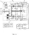
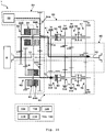
- Fig. 22 shows a second modification of the transmission 1 of the first embodiment.
- the capacity of the odd-numbered stage motor 56 is higher than that of the even-numbered stage motor 86 in the motor power mechanism 20.
- the motor power mechanism 20 includes a gear train 54A for an odd-numbered stage motor and provided to the odd-numbered stage transmission shaft 40, and an odd-numbered stage motor clutch 54B for selectively engaging the odd-numbered stage motor 56 and the odd-numbered stage transmission shaft 40.
- the odd-numbered stage motor 56 is juxtaposed to the engine 2.
- the odd-numbered stage motor clutch 54B is arranged next to the odd-numbered stage main clutch 34.
- the high-capacity odd-numbered stage motor 56 generates large idling loss while it is not used.
- the idling loss of the odd-numbered stage motor 56 is generally prevented by releasing the odd-numbered stage motor clutch 54B. If the odd-numbered stage motor 56 is used for operation for synchronization or operation for regeneration during switching between speed stages, the odd-numbered stage motor clutch 54B is engaged. This can enhance the efficiency of power transmission.
- placing the high-capacity odd-numbered stage motor 56 in juxtaposition to the engine 2 allows the compact size of the transmission 1 in the direction of the shafts.
- the specifications of the odd-numbered stage motor clutch 54B are not limited.
- a wet type multiple disc clutch or a mechanical clutch may be employed as the odd-numbered stage motor clutch 54B.
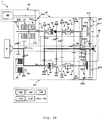
- Fig. 23 shows a transmission 1 of a second embodiment.
- the structure of this transmission 1 is the same as that of the transmission 1 of the first embodiment except for the motor power mechanism 20. Accordingly, the motor power mechanism 20 is mainly described here in detail.
- the motor power mechanism 20 includes a common synchronization motor 22, a gear train 54A for an odd-numbered stage motor and provided to the odd-numbered stage transmission shaft 40, an odd-numbered stage motor clutch 54B for selectively engaging the common synchronization motor 22 and the odd-numbered stage transmission shaft 40, a gear train 84A for an even-numbered stage motor and provided to the even-numbered stage transmission shaft 70, and an even-numbered stage motor clutch 84B for selectively engaging the common synchronization motor 22 and the even-numbered stage transmission shaft 70.
- this can cause both the odd-numbered stage transmission shaft 40 and the even-numbered stage transmission shaft 70 to rotate by using one common synchronization motor 22.
- the odd-numbered stage mechanical clutch 50 is engaged to make the "first speed engaged condition," and at the same time, the odd-numbered stage motor clutch 54B is engaged to cause the common synchronization motor 22 to rotate as shown in Fig. 24 .
- the power of the common synchronization motor 22 is transmitted to the output shaft 92 to allow start by high-torque drive.
- the odd-numbered stage motor 54B or the even-numbered stage motor clutch 84B is engaged to transmit the redundant power or inertial force of the engine 2 to the common synchronization motor 22 for regeneration.
- the even-numbered stage motor clutch 84B is engaged and the common synchronization motor 22 is driven to assist power as shown in Fig. 26 .
- Idling loss to be generated when the common synchronization motor 22 is stopped can be prevented by releasing both the odd-numbered stage motor clutch 54B and the even-numbered stage motor clutch 84B.
- Fig. 27 shows a transmission 1 according to a third embodiment.
- the structure of this transmission 1 is the same as that of the transmission 1 of the first embodiment except for the motor power mechanism 20 and a synchronization shift mechanism 200 described later. Accordingly, the motor power mechanism 20 and the mechanical synchronization mechanism 200 are mainly described here in detail.
- the motor power mechanism 20 includes an odd-numbered stage motor 56, a gear train 54A for an odd-numbered stage motor and provided to the odd-numbered stage transmission shaft 40, and an odd-numbered stage motor clutch 54B for selectively engaging the odd-numbered stage motor 56 and the odd-numbered stage transmission shaft 40.
- the odd-numbered stage motor 56 is used not for the purpose of synchronization, but for the purposes of assisting power for the engine 2 and achieving regeneration.
- the synchronization shift mechanism 200 provides synchronization between the odd-numbered stage shift mechanism 30 and the even-numbered stage shift mechanism 60 during gear shift.
- the synchronization shift mechanism 200 includes a first synchronization gear train 210 and a second synchronization gear train 220.
- the first synchronization gear train 210 selectively engages the odd-numbered stage transmission shaft 40 and the even-numbered stage transmission shaft 70 such that the odd-numbered stage transmission shaft 40 and the even-numbered stage transmission shaft 70 rotate at a first ratio of rotation.
- the first synchronization gear train 210 includes a first synchronization clutch 212 provided to the odd-numbered stage transmission shaft 40, a first odd-numbered stage synchronization gear 214 coupled to the first synchronization clutch 212, a first intermediate synchronization gear 216 provided to the output shaft 92 such that the first intermediate synchronization gear 216 is freely rotatable relative to the output shaft 92 while being in meshing engagement with the first odd-numbered stage synchronization gear 214, and a first even-numbered stage synchronization gear 218 fixed to the even-numbered stage transmission shaft 70 while being in meshing engagement with the first intermediate synchronization gear 216.
- the first odd-numbered stage synchronization gear 214 and the first even-numbered stage synchronization gear 218 have the same number of teeth. Accordingly, the first ratio of rotation is "substantially 1.” Thus, once the first synchronization clutch 212 is connected, the odd-numbered stage transmission shaft 40 and the even-numbered stage transmission shaft 70 rotate at the same speed.
- the second synchronization gear train 220 selectively engages the odd-numbered stage transmission shaft 40 and the even-numbered stage transmission shaft 70 such that the odd-numbered stage transmission shaft 40 and the even-numbered stage transmission shaft 70 rotate at a second ratio of rotation. More specifically, the second synchronization gear train 220 includes a second synchronization clutch 222 provided to the even-numbered stage transmission shaft 70, a second even-numbered stage synchronization gear 224 coupled to the second synchronization clutch 222, a second large-diameter intermediate synchronization gear 226A provided to the output shaft 92 such that the second large-diameter intermediate synchronization gear 226A is freely rotatable relative to the output shaft 92 while being in meshing engagement with the second even-numbered stage synchronization gear 224, a second small-diameter intermediate synchronization gear 226B coaxially coupled to the second large-diameter intermediate synchronization gear 226A and having a smaller number of teeth than the second large-diameter intermediate synchronization gear 226A,
- the second ratio of rotation is different from the first ratio of rotation. More specifically, the second ratio of rotation is the same as a value that is "close to the square of an interstage ratio" between the first to eighth speeds.
- the synchronization shift mechanism accelerates (or decelerates) the idling (or stopped) odd-numbered stage transmission shaft (or even-numbered stage transmission shaft) to the number of rotations for synchronization. Meanwhile, this acceleration (deceleration) is achieved only by inertial force.
- the synchronization shift mechanism can be composed of a small-capacity gear and a small-capacity clutch, allowing the compact size thereof.
- the first synchronization clutch 212 and the second synchronization clutch 222 are engaged with each other while generating a difference in rotation therebetween. Accordingly, wet type multiple disc clutches are used as the first and second synchronization clutches 212 and 222.
- the first synchronization gear train 210 of the synchronization shift mechanism 200 is engaged as shown in Fig. 27 to forcibly make the odd-numbered stage transmission shaft 40 and the even-numbered stage transmission shaft 70 rotate at the same speed (at a ratio of 1).
- This provides synchronization between the rotation of the even-numbered stage transmission shaft 70 and the rotation of the second-speed shift gear train 72, so that the even-numbered stage mechanical clutch 80 can be engaged to make the "second speed engaged condition.” Accordingly, preparations for shift-up to the second speed are completed.
- the second synchronization gear train 220 of the synchronization shift mechanism 200 is engaged as shown in Fig. 28 to forcibly make the odd-numbered stage transmission shaft 40 and the even-numbered stage transmission shaft 70 rotate at a ratio (about 1.66) corresponding to the square of the aforementioned interstage ratio.
- This provides synchronization between the rotation of the odd-numbered stage transmission shaft 40 and the rotation of the third-speed shift gear train 43, so that the odd-numbered stage mechanical clutch 50 can be engaged to make the "third speed engaged condition.” Accordingly, preparations for shift-up to the third speed are completed.
- use of the synchronization shift mechanism 200 realizes mechanical conversion of the speed stages. This allows the odd-numbered stage motor 56 to be dedicated to assisting the engine 2 and regenerating power. In particular, even during running with an engine in an even-numbered stage, engaging the synchronization shift mechanism 200 allows the odd-numbered stage motor 56 to assist power and regenerate power.
- a large dump truck is shown as an example of the use of the transmission 1 of the present embodiments.
- the use of the transmission 1 is not specifically limited, but the transmission 1 may be used for various applications such as a bus, a truck, an automobile, a construction machine, and a diesel railcar.
- the transmission of the present invention is not limited to the embodiments described above.
- the transmission of the invention also covers an embodiment where motors are provided at the respective axial ends of first and second input shafts of Japanese Patent Application Laid-Open No. 2003-269592 .
- twin-clutch type hybrid transmission of the invention can be used for various purposes relating to power transmission.
Applications Claiming Priority (2)
| Application Number | Priority Date | Filing Date | Title |
|---|---|---|---|
| JP2009201352 | 2009-09-01 | ||
| PCT/JP2010/061564 WO2011027616A1 (ja) | 2009-09-01 | 2010-07-07 | ツインクラッチ式ハイブリッド変速機 |
Publications (3)
| Publication Number | Publication Date |
|---|---|
| EP2474759A1 EP2474759A1 (en) | 2012-07-11 |
| EP2474759A4 EP2474759A4 (en) | 2014-04-02 |
| EP2474759B1 true EP2474759B1 (en) | 2017-04-26 |
Family
ID=43649164
Family Applications (1)
| Application Number | Title | Priority Date | Filing Date |
|---|---|---|---|
| EP10813567.4A Active EP2474759B1 (en) | 2009-09-01 | 2010-07-07 | Twin clutch type hybrid transmission |
Country Status (5)
| Country | Link |
|---|---|
| US (1) | US8666614B2 (ja) |
| EP (1) | EP2474759B1 (ja) |
| JP (1) | JP5437380B2 (ja) |
| CN (1) | CN102597572B (ja) |
| WO (1) | WO2011027616A1 (ja) |
Families Citing this family (23)
| Publication number | Priority date | Publication date | Assignee | Title |
|---|---|---|---|---|
| US8887589B2 (en) * | 2010-06-01 | 2014-11-18 | Hitachi Nico Transmission, Co., Ltd. | Twin clutch transmission |
| DE102011077125A1 (de) * | 2011-06-07 | 2012-12-13 | Robert Bosch Gmbh | Verfahren zum Betreiben einer Antriebsvorrichtung sowie Vorrichtung zum Betreiben der Antriebsvorrichtung |
| KR101261955B1 (ko) * | 2011-11-10 | 2013-05-09 | 현대자동차주식회사 | 하이브리드 차량용 시스템 |
| JP2014058286A (ja) | 2012-09-19 | 2014-04-03 | Toyota Motor Corp | ハイブリッド車両の制御装置 |
| JP2014201132A (ja) * | 2013-04-02 | 2014-10-27 | トヨタ自動車株式会社 | 車両の制御装置 |
| KR101519263B1 (ko) * | 2013-12-18 | 2015-05-11 | 현대자동차주식회사 | 하이브리드 차량의 주행 제어방법 |
| EP3374219B1 (en) | 2015-11-09 | 2020-01-15 | Volvo Truck Corporation | A vehicle powertrain |
| DE102016119558A1 (de) * | 2016-10-13 | 2018-04-19 | Getrag Getriebe- Und Zahnradfabrik Hermann Hagenmeyer Gmbh & Cie Kg | Verfahren zum Durchführen eines Kriechladebetriebes und Hybrid-Antriebsstrang hierfür |
| CN106891714B (zh) * | 2017-01-23 | 2023-10-20 | 中国第一汽车股份有限公司 | 一种机动车用三离合机电耦合驱动装置 |
| JP2018154208A (ja) * | 2017-03-16 | 2018-10-04 | 本田技研工業株式会社 | ハイブリッド車両の駆動装置 |
| EP3707409A1 (en) * | 2017-11-09 | 2020-09-16 | CNH Industrial Italia S.P.A. | Improvements in or relating to dual-clutch transmissions |
| CN107830127A (zh) * | 2017-11-30 | 2018-03-23 | 江苏沃得农业机械有限公司 | 拖拉机变速箱的主变速机构 |
| CN108302166A (zh) * | 2018-02-06 | 2018-07-20 | 江苏沃得农业机械有限公司 | 拖拉机变速箱传动装置 |
| IT201800007576A1 (it) * | 2018-07-27 | 2020-01-27 | Cnh Ind Italia Spa | Architettura elettrica ibrida per trasmissione a doppia frizione |
| KR102588935B1 (ko) * | 2018-08-29 | 2023-10-16 | 현대자동차주식회사 | 차량의 파워트레인 |
| IT201900000813A1 (it) * | 2019-01-18 | 2020-07-18 | Cnh Ind Italia Spa | Architettura ibrida elettrica di trasmissione a doppia frizione per veicoli agricoli |
| DE102019007682A1 (de) * | 2019-10-29 | 2021-04-29 | Jenoptik Advanced Systems Gmbh | Schaltgetriebe und Verfahren zum Betreiben eines Schaltgetriebes |
| CN111688470B (zh) * | 2020-05-11 | 2021-11-09 | 同济大学 | 一种串并联构型插电式混合动力系统及其控制方法 |
| CN112253699A (zh) * | 2020-10-28 | 2021-01-22 | 株洲齿轮有限责任公司 | 一种商用车七速双离合变速器 |
| CN114454705B (zh) * | 2020-11-09 | 2023-09-15 | 广州汽车集团股份有限公司 | 混合动力驱动系统及车辆 |
| CN113147354B (zh) * | 2021-05-07 | 2023-05-12 | 一汽解放汽车有限公司 | 混合动力系统 |
| WO2023061950A1 (en) * | 2021-10-11 | 2023-04-20 | Brudeli Green Mobility As | A powertrain and a clutch-motor assembly |
| IT202100032045A1 (it) * | 2021-12-21 | 2023-06-21 | Cnh Ind Italia Spa | Architettura di trasmissione elettrica ibrida migliorata |
Family Cites Families (22)
| Publication number | Priority date | Publication date | Assignee | Title |
|---|---|---|---|---|
| JPH01220761A (ja) | 1988-02-26 | 1989-09-04 | Railway Technical Res Inst | 変速機のクラッチ制御装置 |
| JPH02103555U (ja) | 1989-02-03 | 1990-08-17 | ||
| JP2565596Y2 (ja) | 1991-10-15 | 1998-03-18 | 新潟コンバーター株式会社 | ディーゼル動車用変速機 |
| DE19850549A1 (de) * | 1998-11-03 | 2000-05-04 | Bosch Gmbh Robert | Getriebe für ein Kraftfahrzeug, insbesondere Doppelkupplungs-Schaltgetriebe, und Verfahren zum Betreiben des Getriebes |
| JP3647399B2 (ja) * | 2000-09-14 | 2005-05-11 | 株式会社日立製作所 | 車両用動力伝達システムおよびそれを搭載した自動車 |
| US6427549B1 (en) * | 2001-01-10 | 2002-08-06 | New Venture Gear, Inc. | Dual countershaft twin clutch automated transmission |
| EP1270301A3 (en) * | 2001-06-19 | 2007-02-21 | Hitachi, Ltd. | Power transmission apparatus for automobile |
| JP3738740B2 (ja) | 2002-03-19 | 2006-01-25 | 日産自動車株式会社 | ツインクラッチ式歯車変速機 |
| DE10335262A1 (de) * | 2003-08-01 | 2005-03-03 | Daimlerchrysler Ag | Doppelkupplungsgetriebe mit koaxialem Antrieb und Abtrieb |
| JP4593896B2 (ja) | 2003-09-19 | 2010-12-08 | いすゞ自動車株式会社 | 動力分配装置 |
| JP2006029511A (ja) * | 2004-07-20 | 2006-02-02 | Aisin Ai Co Ltd | 車両用変速操作装置 |
| JP4939049B2 (ja) * | 2005-12-28 | 2012-05-23 | 本田技研工業株式会社 | ツインクラッチ式歯車変速機における変速制御方法 |
| EP1906042B1 (en) * | 2005-12-28 | 2009-04-15 | Honda Motor Co., Ltd. | Twin clutch device |
| KR100852044B1 (ko) * | 2006-07-31 | 2008-08-13 | 현대자동차주식회사 | 하이브리드 전기 차량용 듀얼 클러치 변속기 |
| JP4704308B2 (ja) * | 2006-09-29 | 2011-06-15 | 本田技研工業株式会社 | ツインクラッチ式変速機 |
| JP4696221B2 (ja) * | 2007-03-01 | 2011-06-08 | 三菱自動車工業株式会社 | 同期噛み合い式自動変速装置 |
| EP2060827B1 (de) * | 2007-11-14 | 2011-09-07 | Getrag Ford Transmissions GmbH | Verwendung eines Doppelkupplungsgetriebes in zwei Getriebevarianten |
| US8216110B2 (en) * | 2007-12-05 | 2012-07-10 | Nissan Motor Co., Ltd. | Shifting control system |
| JP4977904B2 (ja) * | 2008-01-31 | 2012-07-18 | 本田技研工業株式会社 | ツインクラッチ式変速装置 |
| JP4281841B1 (ja) * | 2008-02-07 | 2009-06-17 | 三菱自動車工業株式会社 | 車両用変速機 |
| DE102008043385B4 (de) * | 2008-11-03 | 2020-10-15 | Zf Friedrichshafen Ag | Verfahren zur Synchronpunktermittlung eines automatisierten Doppelkupplungsgetriebes |
| WO2010109573A1 (ja) * | 2009-03-23 | 2010-09-30 | トヨタ自動車株式会社 | 車両用駆動装置 |
-
2010
- 2010-07-07 JP JP2011529846A patent/JP5437380B2/ja active Active
- 2010-07-07 US US13/392,968 patent/US8666614B2/en active Active
- 2010-07-07 EP EP10813567.4A patent/EP2474759B1/en active Active
- 2010-07-07 CN CN201080049458.6A patent/CN102597572B/zh active Active
- 2010-07-07 WO PCT/JP2010/061564 patent/WO2011027616A1/ja active Application Filing
Also Published As
| Publication number | Publication date |
|---|---|
| CN102597572A (zh) | 2012-07-18 |
| JP5437380B2 (ja) | 2014-03-12 |
| US20120203412A1 (en) | 2012-08-09 |
| EP2474759A1 (en) | 2012-07-11 |
| JPWO2011027616A1 (ja) | 2013-02-04 |
| US8666614B2 (en) | 2014-03-04 |
| CN102597572B (zh) | 2014-12-03 |
| WO2011027616A1 (ja) | 2011-03-10 |
| EP2474759A4 (en) | 2014-04-02 |
Similar Documents
| Publication | Publication Date | Title |
|---|---|---|
| EP2474759B1 (en) | Twin clutch type hybrid transmission | |
| RU2628618C2 (ru) | Гибридный привод, транспортное средство с таким гибридным приводом, способ управления таким гибридным приводом | |
| JP4228954B2 (ja) | ハイブリッド車の駆動装置 | |
| JP4704494B2 (ja) | 動力出力装置 | |
| US8948945B2 (en) | Hybrid vehicle | |
| JP4229156B2 (ja) | 動力出力装置およびハイブリッド自動車 | |
| JP3960478B2 (ja) | トランスミッションシステムと車両推進方法 | |
| US9695932B2 (en) | Power transmission apparatus for vehicle | |
| US8721491B2 (en) | Powertrain with hybrid transmission | |
| JP5207913B2 (ja) | ハイブリッド自動車の駆動装置 | |
| WO2011021517A1 (ja) | ハイブリッド車両のエンジン始動制御装置 | |
| JP5619142B2 (ja) | 車両用駆動装置 | |
| JP2005163946A (ja) | 自動車の駆動装置および駆動方法 | |
| JP5198348B2 (ja) | ハイブリッド車両用トランスミッション | |
| CN104968546A (zh) | 混合动力车辆 | |
| JP4779936B2 (ja) | ハイブリッド駆動装置 | |
| JP2010234923A (ja) | ハイブリッド駆動装置 | |
| JP3758650B2 (ja) | ハイブリッド駆動装置の制御装置 | |
| JP4872697B2 (ja) | 動力伝達システム | |
| JP5478329B2 (ja) | 車両用駆動装置 | |
| JP7091981B2 (ja) | ハイブリッド車両の制御装置 | |
| JP2011230742A (ja) | ハイブリッド車両 | |
| JP2011213162A (ja) | 車両用駆動装置の制御装置 | |
| CN111267602A (zh) | 混动机动车的变速器单元、动力传动系和执行换挡的方法 | |
| JP2008232199A (ja) | 自動車用駆動装置 |
Legal Events
| Date | Code | Title | Description |
|---|---|---|---|
| PUAI | Public reference made under article 153(3) epc to a published international application that has entered the european phase |
Free format text: ORIGINAL CODE: 0009012 |
|
| 17P | Request for examination filed |
Effective date: 20120330 |
|
| AK | Designated contracting states |
Kind code of ref document: A1 Designated state(s): AL AT BE BG CH CY CZ DE DK EE ES FI FR GB GR HR HU IE IS IT LI LT LU LV MC MK MT NL NO PL PT RO SE SI SK SM TR |
|
| DAX | Request for extension of the european patent (deleted) | ||
| A4 | Supplementary search report drawn up and despatched |
Effective date: 20140305 |
|
| RIC1 | Information provided on ipc code assigned before grant |
Ipc: B60W 10/113 20120101ALI20140227BHEP Ipc: F16H 3/093 20060101AFI20140227BHEP Ipc: B60W 20/00 20060101ALI20140227BHEP Ipc: B60K 6/442 20071001ALI20140227BHEP |
|
| REG | Reference to a national code |
Ref country code: DE Ref legal event code: R079 Ref document number: 602010041911 Country of ref document: DE Free format text: PREVIOUS MAIN CLASS: F16H0003093000 Ipc: B60K0006480000 |
|
| GRAP | Despatch of communication of intention to grant a patent |
Free format text: ORIGINAL CODE: EPIDOSNIGR1 |
|
| RIC1 | Information provided on ipc code assigned before grant |
Ipc: B60L 11/14 20060101ALI20161104BHEP Ipc: B60K 6/442 20071001ALI20161104BHEP Ipc: B60L 15/20 20060101ALI20161104BHEP Ipc: B60K 6/547 20071001ALI20161104BHEP Ipc: B60L 7/14 20060101ALI20161104BHEP Ipc: B60K 6/48 20071001AFI20161104BHEP Ipc: F16H 3/00 20060101ALI20161104BHEP Ipc: B60W 10/113 20120101ALI20161104BHEP |
|
| INTG | Intention to grant announced |
Effective date: 20161121 |
|
| GRAS | Grant fee paid |
Free format text: ORIGINAL CODE: EPIDOSNIGR3 |
|
| GRAA | (expected) grant |
Free format text: ORIGINAL CODE: 0009210 |
|
| AK | Designated contracting states |
Kind code of ref document: B1 Designated state(s): AL AT BE BG CH CY CZ DE DK EE ES FI FR GB GR HR HU IE IS IT LI LT LU LV MC MK MT NL NO PL PT RO SE SI SK SM TR |
|
| REG | Reference to a national code |
Ref country code: GB Ref legal event code: FG4D |
|
| REG | Reference to a national code |
Ref country code: CH Ref legal event code: EP |
|
| REG | Reference to a national code |
Ref country code: AT Ref legal event code: REF Ref document number: 887551 Country of ref document: AT Kind code of ref document: T Effective date: 20170515 |
|
| REG | Reference to a national code |
Ref country code: IE Ref legal event code: FG4D |
|
| REG | Reference to a national code |
Ref country code: DE Ref legal event code: R096 Ref document number: 602010041911 Country of ref document: DE |
|
| REG | Reference to a national code |
Ref country code: NL Ref legal event code: MP Effective date: 20170426 |
|
| REG | Reference to a national code |
Ref country code: LT Ref legal event code: MG4D |
|
| REG | Reference to a national code |
Ref country code: AT Ref legal event code: MK05 Ref document number: 887551 Country of ref document: AT Kind code of ref document: T Effective date: 20170426 |
|
| PG25 | Lapsed in a contracting state [announced via postgrant information from national office to epo] |
Ref country code: NL Free format text: LAPSE BECAUSE OF FAILURE TO SUBMIT A TRANSLATION OF THE DESCRIPTION OR TO PAY THE FEE WITHIN THE PRESCRIBED TIME-LIMIT Effective date: 20170426 |
|
| PG25 | Lapsed in a contracting state [announced via postgrant information from national office to epo] |
Ref country code: NO Free format text: LAPSE BECAUSE OF FAILURE TO SUBMIT A TRANSLATION OF THE DESCRIPTION OR TO PAY THE FEE WITHIN THE PRESCRIBED TIME-LIMIT Effective date: 20170726 Ref country code: HR Free format text: LAPSE BECAUSE OF FAILURE TO SUBMIT A TRANSLATION OF THE DESCRIPTION OR TO PAY THE FEE WITHIN THE PRESCRIBED TIME-LIMIT Effective date: 20170426 Ref country code: GR Free format text: LAPSE BECAUSE OF FAILURE TO SUBMIT A TRANSLATION OF THE DESCRIPTION OR TO PAY THE FEE WITHIN THE PRESCRIBED TIME-LIMIT Effective date: 20170727 Ref country code: FI Free format text: LAPSE BECAUSE OF FAILURE TO SUBMIT A TRANSLATION OF THE DESCRIPTION OR TO PAY THE FEE WITHIN THE PRESCRIBED TIME-LIMIT Effective date: 20170426 Ref country code: ES Free format text: LAPSE BECAUSE OF FAILURE TO SUBMIT A TRANSLATION OF THE DESCRIPTION OR TO PAY THE FEE WITHIN THE PRESCRIBED TIME-LIMIT Effective date: 20170426 Ref country code: AT Free format text: LAPSE BECAUSE OF FAILURE TO SUBMIT A TRANSLATION OF THE DESCRIPTION OR TO PAY THE FEE WITHIN THE PRESCRIBED TIME-LIMIT Effective date: 20170426 Ref country code: LT Free format text: LAPSE BECAUSE OF FAILURE TO SUBMIT A TRANSLATION OF THE DESCRIPTION OR TO PAY THE FEE WITHIN THE PRESCRIBED TIME-LIMIT Effective date: 20170426 |
|
| PG25 | Lapsed in a contracting state [announced via postgrant information from national office to epo] |
Ref country code: IS Free format text: LAPSE BECAUSE OF FAILURE TO SUBMIT A TRANSLATION OF THE DESCRIPTION OR TO PAY THE FEE WITHIN THE PRESCRIBED TIME-LIMIT Effective date: 20170826 Ref country code: BG Free format text: LAPSE BECAUSE OF FAILURE TO SUBMIT A TRANSLATION OF THE DESCRIPTION OR TO PAY THE FEE WITHIN THE PRESCRIBED TIME-LIMIT Effective date: 20170726 Ref country code: LV Free format text: LAPSE BECAUSE OF FAILURE TO SUBMIT A TRANSLATION OF THE DESCRIPTION OR TO PAY THE FEE WITHIN THE PRESCRIBED TIME-LIMIT Effective date: 20170426 Ref country code: PL Free format text: LAPSE BECAUSE OF FAILURE TO SUBMIT A TRANSLATION OF THE DESCRIPTION OR TO PAY THE FEE WITHIN THE PRESCRIBED TIME-LIMIT Effective date: 20170426 Ref country code: SE Free format text: LAPSE BECAUSE OF FAILURE TO SUBMIT A TRANSLATION OF THE DESCRIPTION OR TO PAY THE FEE WITHIN THE PRESCRIBED TIME-LIMIT Effective date: 20170426 |
|
| REG | Reference to a national code |
Ref country code: DE Ref legal event code: R097 Ref document number: 602010041911 Country of ref document: DE |
|
| PG25 | Lapsed in a contracting state [announced via postgrant information from national office to epo] |
Ref country code: EE Free format text: LAPSE BECAUSE OF FAILURE TO SUBMIT A TRANSLATION OF THE DESCRIPTION OR TO PAY THE FEE WITHIN THE PRESCRIBED TIME-LIMIT Effective date: 20170426 Ref country code: DK Free format text: LAPSE BECAUSE OF FAILURE TO SUBMIT A TRANSLATION OF THE DESCRIPTION OR TO PAY THE FEE WITHIN THE PRESCRIBED TIME-LIMIT Effective date: 20170426 Ref country code: SK Free format text: LAPSE BECAUSE OF FAILURE TO SUBMIT A TRANSLATION OF THE DESCRIPTION OR TO PAY THE FEE WITHIN THE PRESCRIBED TIME-LIMIT Effective date: 20170426 Ref country code: CZ Free format text: LAPSE BECAUSE OF FAILURE TO SUBMIT A TRANSLATION OF THE DESCRIPTION OR TO PAY THE FEE WITHIN THE PRESCRIBED TIME-LIMIT Effective date: 20170426 Ref country code: RO Free format text: LAPSE BECAUSE OF FAILURE TO SUBMIT A TRANSLATION OF THE DESCRIPTION OR TO PAY THE FEE WITHIN THE PRESCRIBED TIME-LIMIT Effective date: 20170426 |
|
| PG25 | Lapsed in a contracting state [announced via postgrant information from national office to epo] |
Ref country code: SM Free format text: LAPSE BECAUSE OF FAILURE TO SUBMIT A TRANSLATION OF THE DESCRIPTION OR TO PAY THE FEE WITHIN THE PRESCRIBED TIME-LIMIT Effective date: 20170426 Ref country code: IT Free format text: LAPSE BECAUSE OF FAILURE TO SUBMIT A TRANSLATION OF THE DESCRIPTION OR TO PAY THE FEE WITHIN THE PRESCRIBED TIME-LIMIT Effective date: 20170426 |
|
| REG | Reference to a national code |
Ref country code: CH Ref legal event code: PL |
|
| PLBE | No opposition filed within time limit |
Free format text: ORIGINAL CODE: 0009261 |
|
| STAA | Information on the status of an ep patent application or granted ep patent |
Free format text: STATUS: NO OPPOSITION FILED WITHIN TIME LIMIT |
|
| GBPC | Gb: european patent ceased through non-payment of renewal fee |
Effective date: 20170726 |
|
| 26N | No opposition filed |
Effective date: 20180129 |
|
| REG | Reference to a national code |
Ref country code: IE Ref legal event code: MM4A |
|
| REG | Reference to a national code |
Ref country code: FR Ref legal event code: ST Effective date: 20180330 |
|
| PG25 | Lapsed in a contracting state [announced via postgrant information from national office to epo] |
Ref country code: LI Free format text: LAPSE BECAUSE OF NON-PAYMENT OF DUE FEES Effective date: 20170731 Ref country code: CH Free format text: LAPSE BECAUSE OF NON-PAYMENT OF DUE FEES Effective date: 20170731 Ref country code: IE Free format text: LAPSE BECAUSE OF NON-PAYMENT OF DUE FEES Effective date: 20170707 Ref country code: GB Free format text: LAPSE BECAUSE OF NON-PAYMENT OF DUE FEES Effective date: 20170726 |
|
| PG25 | Lapsed in a contracting state [announced via postgrant information from national office to epo] |
Ref country code: FR Free format text: LAPSE BECAUSE OF NON-PAYMENT OF DUE FEES Effective date: 20170731 Ref country code: SI Free format text: LAPSE BECAUSE OF FAILURE TO SUBMIT A TRANSLATION OF THE DESCRIPTION OR TO PAY THE FEE WITHIN THE PRESCRIBED TIME-LIMIT Effective date: 20170426 |
|
| REG | Reference to a national code |
Ref country code: BE Ref legal event code: MM Effective date: 20170731 |
|
| PG25 | Lapsed in a contracting state [announced via postgrant information from national office to epo] |
Ref country code: LU Free format text: LAPSE BECAUSE OF NON-PAYMENT OF DUE FEES Effective date: 20170707 |
|
| PG25 | Lapsed in a contracting state [announced via postgrant information from national office to epo] |
Ref country code: BE Free format text: LAPSE BECAUSE OF NON-PAYMENT OF DUE FEES Effective date: 20170731 |
|
| PG25 | Lapsed in a contracting state [announced via postgrant information from national office to epo] |
Ref country code: MT Free format text: LAPSE BECAUSE OF NON-PAYMENT OF DUE FEES Effective date: 20170707 |
|
| RIC2 | Information provided on ipc code assigned after grant |
Ipc: B60L 11/14 20060101ALI20161104BHEP Ipc: B60K 6/48 20071001AFI20161104BHEP Ipc: F16H 3/00 20060101ALI20161104BHEP Ipc: B60K 6/442 20071001ALI20161104BHEP Ipc: B60K 6/547 20071001ALI20161104BHEP Ipc: B60L 7/14 20060101ALI20161104BHEP Ipc: B60W 10/113 20120101ALI20161104BHEP Ipc: B60L 15/20 20060101ALI20161104BHEP |
|
| PG25 | Lapsed in a contracting state [announced via postgrant information from national office to epo] |
Ref country code: HU Free format text: LAPSE BECAUSE OF FAILURE TO SUBMIT A TRANSLATION OF THE DESCRIPTION OR TO PAY THE FEE WITHIN THE PRESCRIBED TIME-LIMIT; INVALID AB INITIO Effective date: 20100707 Ref country code: MC Free format text: LAPSE BECAUSE OF FAILURE TO SUBMIT A TRANSLATION OF THE DESCRIPTION OR TO PAY THE FEE WITHIN THE PRESCRIBED TIME-LIMIT Effective date: 20170426 |
|
| PG25 | Lapsed in a contracting state [announced via postgrant information from national office to epo] |
Ref country code: CY Free format text: LAPSE BECAUSE OF NON-PAYMENT OF DUE FEES Effective date: 20170426 |
|
| PG25 | Lapsed in a contracting state [announced via postgrant information from national office to epo] |
Ref country code: MK Free format text: LAPSE BECAUSE OF FAILURE TO SUBMIT A TRANSLATION OF THE DESCRIPTION OR TO PAY THE FEE WITHIN THE PRESCRIBED TIME-LIMIT Effective date: 20170426 |
|
| PG25 | Lapsed in a contracting state [announced via postgrant information from national office to epo] |
Ref country code: TR Free format text: LAPSE BECAUSE OF FAILURE TO SUBMIT A TRANSLATION OF THE DESCRIPTION OR TO PAY THE FEE WITHIN THE PRESCRIBED TIME-LIMIT Effective date: 20170426 |
|
| PG25 | Lapsed in a contracting state [announced via postgrant information from national office to epo] |
Ref country code: PT Free format text: LAPSE BECAUSE OF FAILURE TO SUBMIT A TRANSLATION OF THE DESCRIPTION OR TO PAY THE FEE WITHIN THE PRESCRIBED TIME-LIMIT Effective date: 20170426 |
|
| PG25 | Lapsed in a contracting state [announced via postgrant information from national office to epo] |
Ref country code: AL Free format text: LAPSE BECAUSE OF FAILURE TO SUBMIT A TRANSLATION OF THE DESCRIPTION OR TO PAY THE FEE WITHIN THE PRESCRIBED TIME-LIMIT Effective date: 20170426 |
|
| PGFP | Annual fee paid to national office [announced via postgrant information from national office to epo] |
Ref country code: DE Payment date: 20230727 Year of fee payment: 14 |