EP2471646A2 - Spritzgiesswerkzeug - Google Patents
Spritzgiesswerkzeug Download PDFInfo
- Publication number
- EP2471646A2 EP2471646A2 EP11173023A EP11173023A EP2471646A2 EP 2471646 A2 EP2471646 A2 EP 2471646A2 EP 11173023 A EP11173023 A EP 11173023A EP 11173023 A EP11173023 A EP 11173023A EP 2471646 A2 EP2471646 A2 EP 2471646A2
- Authority
- EP
- European Patent Office
- Prior art keywords
- insert
- resilient contact
- contact member
- mold assembly
- mold
- Prior art date
- Legal status (The legal status is an assumption and is not a legal conclusion. Google has not performed a legal analysis and makes no representation as to the accuracy of the status listed.)
- Withdrawn
Links
Images


Classifications
-
- B—PERFORMING OPERATIONS; TRANSPORTING
- B29—WORKING OF PLASTICS; WORKING OF SUBSTANCES IN A PLASTIC STATE IN GENERAL
- B29C—SHAPING OR JOINING OF PLASTICS; SHAPING OF MATERIAL IN A PLASTIC STATE, NOT OTHERWISE PROVIDED FOR; AFTER-TREATMENT OF THE SHAPED PRODUCTS, e.g. REPAIRING
- B29C45/00—Injection moulding, i.e. forcing the required volume of moulding material through a nozzle into a closed mould; Apparatus therefor
- B29C45/14—Injection moulding, i.e. forcing the required volume of moulding material through a nozzle into a closed mould; Apparatus therefor incorporating preformed parts or layers, e.g. injection moulding around inserts or for coating articles
- B29C45/14836—Preventing damage of inserts during injection, e.g. collapse of hollow inserts, breakage
-
- B—PERFORMING OPERATIONS; TRANSPORTING
- B29—WORKING OF PLASTICS; WORKING OF SUBSTANCES IN A PLASTIC STATE IN GENERAL
- B29C—SHAPING OR JOINING OF PLASTICS; SHAPING OF MATERIAL IN A PLASTIC STATE, NOT OTHERWISE PROVIDED FOR; AFTER-TREATMENT OF THE SHAPED PRODUCTS, e.g. REPAIRING
- B29C33/00—Moulds or cores; Details thereof or accessories therefor
- B29C33/38—Moulds or cores; Details thereof or accessories therefor characterised by the material or the manufacturing process
- B29C33/40—Plastics, e.g. foam or rubber
- B29C33/405—Elastomers, e.g. rubber
-
- B—PERFORMING OPERATIONS; TRANSPORTING
- B29—WORKING OF PLASTICS; WORKING OF SUBSTANCES IN A PLASTIC STATE IN GENERAL
- B29C—SHAPING OR JOINING OF PLASTICS; SHAPING OF MATERIAL IN A PLASTIC STATE, NOT OTHERWISE PROVIDED FOR; AFTER-TREATMENT OF THE SHAPED PRODUCTS, e.g. REPAIRING
- B29C33/00—Moulds or cores; Details thereof or accessories therefor
- B29C33/56—Coatings, e.g. enameled or galvanised; Releasing, lubricating or separating agents
- B29C33/565—Consisting of shell-like structures supported by backing material
-
- B—PERFORMING OPERATIONS; TRANSPORTING
- B29—WORKING OF PLASTICS; WORKING OF SUBSTANCES IN A PLASTIC STATE IN GENERAL
- B29C—SHAPING OR JOINING OF PLASTICS; SHAPING OF MATERIAL IN A PLASTIC STATE, NOT OTHERWISE PROVIDED FOR; AFTER-TREATMENT OF THE SHAPED PRODUCTS, e.g. REPAIRING
- B29C45/00—Injection moulding, i.e. forcing the required volume of moulding material through a nozzle into a closed mould; Apparatus therefor
- B29C45/14—Injection moulding, i.e. forcing the required volume of moulding material through a nozzle into a closed mould; Apparatus therefor incorporating preformed parts or layers, e.g. injection moulding around inserts or for coating articles
- B29C45/14065—Positioning or centering articles in the mould
-
- B—PERFORMING OPERATIONS; TRANSPORTING
- B29—WORKING OF PLASTICS; WORKING OF SUBSTANCES IN A PLASTIC STATE IN GENERAL
- B29C—SHAPING OR JOINING OF PLASTICS; SHAPING OF MATERIAL IN A PLASTIC STATE, NOT OTHERWISE PROVIDED FOR; AFTER-TREATMENT OF THE SHAPED PRODUCTS, e.g. REPAIRING
- B29C45/00—Injection moulding, i.e. forcing the required volume of moulding material through a nozzle into a closed mould; Apparatus therefor
- B29C45/17—Component parts, details or accessories; Auxiliary operations
- B29C45/26—Moulds
- B29C45/37—Mould cavity walls, i.e. the inner surface forming the mould cavity, e.g. linings
-
- B—PERFORMING OPERATIONS; TRANSPORTING
- B29—WORKING OF PLASTICS; WORKING OF SUBSTANCES IN A PLASTIC STATE IN GENERAL
- B29C—SHAPING OR JOINING OF PLASTICS; SHAPING OF MATERIAL IN A PLASTIC STATE, NOT OTHERWISE PROVIDED FOR; AFTER-TREATMENT OF THE SHAPED PRODUCTS, e.g. REPAIRING
- B29C45/00—Injection moulding, i.e. forcing the required volume of moulding material through a nozzle into a closed mould; Apparatus therefor
- B29C45/14—Injection moulding, i.e. forcing the required volume of moulding material through a nozzle into a closed mould; Apparatus therefor incorporating preformed parts or layers, e.g. injection moulding around inserts or for coating articles
- B29C45/14065—Positioning or centering articles in the mould
- B29C2045/14122—Positioning or centering articles in the mould using fixed mould wall projections for centering the insert
-
- B—PERFORMING OPERATIONS; TRANSPORTING
- B29—WORKING OF PLASTICS; WORKING OF SUBSTANCES IN A PLASTIC STATE IN GENERAL
- B29C—SHAPING OR JOINING OF PLASTICS; SHAPING OF MATERIAL IN A PLASTIC STATE, NOT OTHERWISE PROVIDED FOR; AFTER-TREATMENT OF THE SHAPED PRODUCTS, e.g. REPAIRING
- B29C45/00—Injection moulding, i.e. forcing the required volume of moulding material through a nozzle into a closed mould; Apparatus therefor
- B29C45/14—Injection moulding, i.e. forcing the required volume of moulding material through a nozzle into a closed mould; Apparatus therefor incorporating preformed parts or layers, e.g. injection moulding around inserts or for coating articles
- B29C2045/1486—Details, accessories and auxiliary operations
- B29C2045/14934—Preventing penetration of injected material between insert and adjacent mould wall
Definitions
- the present invention relates generally to a mold assembly according to the pre-characterizing clauses of claims 1 and 13, and more specifically to a mold assembly having at least a resilient contact member particularly suited for the art of applying an insert-molding to a heterogeneous object.
- a conventional mold assembly is typically composed of a rigid mold assembly that is used for insert-molding a part such as a heterogeneous object.
- the material of the rigid mold assembly may be metal such as aluminum, iron, steel, etc.
- the rigid mold assembly typically has an upper mold and a lower mold, and an inner space is provided between the upper mold and the lower mold.
- the aforesaid part may include a non-elastic part and an elastic part combined with the non-elastic part.
- One drawback of the prior art is the interference between the part and the rigid mold assembly that occurs due to self-dimensional variation of the non-elastic part, deformation of the non-elastic part caused by thermal expansion, or hardness of the non-elastic part.
- interference occurs between the non-elastic part and the lower mold, thus damaging the appearance of the non-elastic part.
- the interference between the part and rigid mold assembly can also occur due to thermal expansion during the insert-molding process, so that the appearance of the part may be damaged.
- the present invention aims at providing a mold assembly having at least a resilient contact member.
- the claimed mold assembly for insert-molding a heterogeneous object includes an upper mold and a lower mold.
- the upper mold includes a cavity for accommodating an insert object.
- the lower mold includes a rigid body and a resilient contact member.
- the insert object is disposed on the resilient contact member during an insert molding process, such that the resilient contact member absorbs a dimensional variation of the insert object during the insert molding process.
- a mold assembly includes an upper mold and a lower mold.
- the upper mold includes a first rigid body and a first resilient contact member.
- the lower mold includes a second rigid body and a second resilient contact member. The upper mold and the lower mold, when combined together, define an inner space for accommodating an insert object, wherein the insert object contacts both the first resilient contact member and the second resilient contact member, thereby absorbing a dimensional variation of the insert object.
- the present invention provides a mold assembly having at least a resilient contact member using for contacting an insert object accommodated in the mold assembly, such that the insert object does not contact the rigid part of the mold assembly.
- a polymer elastomer injected into the mold assembly to form a heterogeneous object forming by bonding the insert object with polymer elastomer overflow of the polymer elastomer or damage of the insert object caused by dimensional variation of the insert object will not occur.
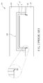
- FIG. 1 and FIG.2 are cross-sectional views of a conventional mold assembly.
- a rigid mold assembly 100 is used for insert-molding a part 10 such as a heterogeneous object.
- the material of the rigid mold assembly 100 may be metal such as aluminum, iron, steel, etc.
- the rigid mold assembly 100 has an upper mold 1 10 and a lower mold 120, and an inner space 130 is formed between the upper mold 1 10 and the lower mold 1 20.
- the part 10 may include a non-elastic part 2 and an elastic part 4 combined with the non-elastic part 2, wherein the non-elastic part 2 may be non-polymer elastomer such as metal, ceramic, glass, plastic, etc.
- a method of forming the part 10 may be: disposing the non-elastic part 2 in the inner space 1 30, then injecting the polymer elastomer into the inner space 130 and curing the polymer elastomer, at which point the part 10 is completed.
- Clearance or interference between the part 10 and the rigid mold assembly 100 occurs due to self-dimensional variation of the non-elastic part 2, deformation of the non-elastic part 2 caused by thermal expansion, or hardness of the non-elastic part 2.
- the gap 140 occurs between the non-elastic part 2 and the lower mold 120. The gap 140 will lead to overflow of the injected polymer elastomer which may be difficult to clean in post processing. As a result, the processing yield is reduced.
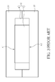
- FIG. 3 is a cross-sectional view of another conventional mold assembly.
- the elastic part 4 is combined on two sides of the non-elastic part 2, and the upper side A1 and the lower side A2 of the non-elastic part 2 respectively contact the upper mold 1 10 and the lower mold 1 20. Due to the lack of resilience and deformation capability of the non-elastic part 2, upper mold 110, and lower mold 1 20, the non-elastic part 2 is easily crushed or damaged by the upper mold 110 and the lower mold 120 when the size of the non-elastic part 2 is too big. On the other hand, as shown in FIG.4 , when the size of the non-elastic part 2 is too small, overflow of the polymer elastomer will occur after mold-locking.
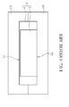
- FIG. 5 depicts a cross-sectional view of a mold assembly in accordance with a first embodiment of the present invention.
- FIG. 6 depicts a cross-sectional view of the mold assembly of FIG.5 after die locking.
- the mold assembly 200 includes an upper mold 210 and a lower mold 220.
- the lower mold 220 includes a rigid body 222 and a resilient contact member 224 located on an inner side S1 of the rigid body 222.
- the upper mold 210 includes a cavity 21 2 for accommodating an insert object 24.
- the insert object 24 is disposed on the resilient contact member 224.
- the upper mold 210 and the lower mold 220 when combined together, define an inner space 230.
- the mold assembly 200 is not limited to the upper mold 210 and the lower mold 220 and the mold numbers of the mold assembly 200 depend on actual demands.
- the relative position of the upper mold 210 and the lower mold 220 can also change according to requirements.
- the polymer elastomer 22 is injected into the inner space 230 to fill the inner space 230. After the polymer elastomer 22 is cured, the polymer elastomer 22 bonds with the insert object 24 to form a heterogeneous object 20.
- the dimensional variation of the insert object 24 can be absorbed during an insert-molding process due to the material of the resilient contact member 224 being an elastic material, wherein the dimensional variation of the insert object 24 may be generated during manufacturing processes or generated by expansion and contraction during insert-molding processes.
- the present invention provides the mold assembly 200 for insert-molding a heterogeneous object 20 that can improve the processing yield.
- the materials of the upper mold 210 and the rigid body 222 may be rigid materials such as aluminum, steel, metal alloys, etc.
- the upper mold 210 and the rigid body 222 are high-temperature proof materials that can resist the molding temperature during insert-molding process.
- the resilient contact member 224 and the polymer elastomer 22 are composed of polymer elastic materials such as silica gel, plastic, synthetic rubber, resins, etc. It should be noted that the resilient contact member 224 and the polymer elastomer 22 are made of different materials so that the resilient contact member 224 and the polymer elastomer 22 will not combine to form one piece during the insert molding process.
- the polymer elastomer 22 may be composed of silica gel while the resilient contact member 224 is composed of a synthetic rubber, or the polymer elastomer 22 may be composed of a synthetic rubber while the resilient contact member 224 is composed of silica gel.
- the polymer elastomer 22 and the resilient contact member 224 cannot both be silica gel or synthetic rubbers at the same time. The reason is that the polymer elastomer 22 injected into molds during the insert-molding process is molten, so it will combine with the insert object 24 after curing. As a result, the polymer elastomer 22 and the insert object 24 would melt and combine into one piece, leading to the heterogeneous object 20 being unable to be mold released after molding.
- FIG. 7 depicts a three-dimensional side view of a heterogeneous object in accordance with an embodiment of the present invention.
- the heterogeneous object 20 may be a notebook or cell phone having a polymer elastomer 22 and an insert object 24, wherein the insert object 24 may be a portion of a case of a notebook or a cell phone, and the polymer elastomer 22 may be a soft film covering the case.
- the heterogeneous object 20 may be other parts and is not limited thereto.
- the patterned surface S2 of the polymer elastomer 22 tightly combines with the corresponding patterned surface S3 of the insert object 24, wherein the material of the polymer elastomer 22 may be a polymer elastic material such as silicon gel, rubber, etc., and the material of the insert object 24 may be a non-polymer elastic material such as aluminum alloy, plastic steel, plastic, ceramic or glass.
- the relative position of the polymer elastomer 22 and the insert object 24 may change as long as the materials of the polymer elastomer 22 and the insert object 24 are different. Additionally, the shape, the size and the numbers of the pattern P using for fixing and bonding the polymer elastomer 22 with the insert object 24 depend upon practical considerations.
- a profile of a contact surface 54 of the resilient contact member 224 conforms to a bottom surface 55 of the insert object 24. That is, the resilient contact member 224 and the insert object 24 can be combined with the largest contact area, therefore sliding, gaps or interference between the resilient contact member 224 and the insert object 24 leading to overflow of the polymer elastomer 22 or damage of the insert object 24 during insert molding process is avoided.
- the insert object 24 does not contact the upper mold 210 or the rigid body 222, so that clearance or interference during molding caused by lack of resilience and deformation of the insert object 24, the upper mold 210 and the rigid body 222 is avoided.
- the resilient contact member 224 may be fixed on the inner side S1 of the rigid body 222 for avoiding misalignment of the insert object 24 above the resilient contact member 224 due to dislocation of the resilient contact member 224 caused by expansion and contraction in a high temperature process or temperature changing environment.
- the resilient contact member 224 can bond with the rigid body 222 via a primer.
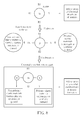
- One kind of combination principle of the primer is shown in FIG.8 , wherein -OH bonding generated after silane primers hydrolyzing can bond with non-polymer elastomers such as metal, ceramic, glass, plastic, etc., so that the resilient contact member 224 and the rigid body 222 can combine with high bonding strength and still have good dimensional stability after repeated operations.
- the present invention is not limited to using primers between the resilient contact member 224 and the rigid body 222.
- the resilient contact member 224 having high temperature resistance can be formed first and then embedded into the mold assembly 200 as a portion of the mold assembly 200.
- the benefit of the forming method is that the resilient contact member 224 can be replaced faster than in the prior art.
- the insert object 24 and the polymer elastomer 22 may be combined via the primer shown in FIG.6 . In doing so, the insert object 24 and the polymer elastomer 22 can be formed stably and the size accuracy of the insert object 24 and the polymer elastomer 22 can be maintained after molding.
- the primer bonding the resilient contact member 224 and the rigid body 222 is not always the same as the primer bonding the insert object 24 and the polymer elastomer 22, and depends on the characteristics of the materials of these components.
- FIG. 9 depicts a cross-sectional view of a mold assembly in accordance with a second embodiment of the present invention.
- the mold assembly 300 includes an upper mold 310 and a lower mold 320.
- the upper mold 310 includes a first rigid body 312 and a first resilient contact member 314, and the lower mold 320 includes a second rigid body 322 and a second resilient contact member 324.
- the upper mold 310 and the lower mold 320 have upper and lower symmetry, but they also can be a non-symmetrical structure in another embodiment.
- the mold assembly 300 is not limited to including only the upper mold 310 and the lower mold 320, and the mold numbers of the mold assembly 300 may change according to requirement.
- the relative position of the upper mold 310 and the lower mold 320 can also change according to requirement.
- an inner space 330 for accommodating an insert object 24' is defined.
- a polymer elastomer 22' is injected into the inner space 330 to fill the remaining space of the inner space 330, so that the polymer elastomer 22'bonds with the insert object 24' to form a heterogeneous object 20'.
- the first resilient contact member 314 and the second resilient contact member 324 clamp the insert object 24' thereby absorbing dimensional variations of the insert object 24'.
- first rigid body 312 and the second rigid body 322 may be composed of rigid materials such as metal, alloy etc.
- the insert object 24' includes non- polymer materials such as metal, plastic, ceramic, glass etc.
- the first resilient contact member 314, the second resilient contact member 324 and the polymer elastomer 22' may be polymer elastic materials such as silicon gel, plastic, synthetic rubber, resin, etc.
- the first resilient contact member 314 and the second resilient contact member 324 may be composed of different materials, and the first rigid body 312 and the second rigid body 322 may be composed of different materials as well, depending upon requirements.
- the materials of the first resilient contact member 314 and the second resilient contact member 324 are different from the materials of the polymer elastomer 22', because the polymer elastomer 22' respectively contacts the first resilient contact member 314 and the second resilient contact member 324.
- the polymer elastomer 22' may be composed of silicon gel while the first and the second resilient contact member 314, 324 are composed of synthetic rubber, or the polymer elastomer 22' may be composed of synthetic rubber while the first and the second resilient contact member 314, 324 are composed of silicon gel, but the invention is not limited thereto.
- the polymer elastomer 22' injected into molds during the insert-molding process is molten, so it will combine with the first resilient contact member 314 or the second resilient contact member 324 as the material of the polymer elastomer 22' is the same as the materials of the first resilient contact member 314 or the second resilient contact member 324.
- the polymer elastomer 22' and the first resilient contact member 314 or the second resilient contact member 324 will melt and combine into one piece, leading to the heterogeneous object 20' being unable to be mold released after molding.
- the profile of the first resilient contact member 314 and the second resilient contact member 324 conforms to the interface S6, S7 of the insert object 24' for fixing the relative position of the insert object 24' and the first and the second resilient contact member 314, 324. This avoids clearance between the first resilient contact member 314 and the insert object 24' or the second resilient contact member 324 and the insert object 24', and avoids interference between the first rigid body 312 and the insert object 24' or the second rigid body 322 and the insert object 24' caused by the slide of the insert object 24'.
- the first resilient contact member 314 is fixed on the inner side S8 of the first rigid body 312, or the second resilient contact member 324 is fixed on the inner side S9 of the second rigid body 322. Therefore, misalignment of the insert object 24, due to dislocation of the first resilient contact member 314 or the second resilient contact member 324 caused by expansion and contraction in a high temperature process or temperature changing environment, is avoided.
- the first resilient contact member 314 or the second resilient contact member 324 can respectively bond with the first rigid body 312 or the second rigid body 322 via a primer, wherein the primer makes the first resilient contact member 314 or the second resilient contact member 324 combine with the first rigid body 312 or the second rigid body 322 with high bonding strength while still retaining good dimensional stability after repeated operations.
- the present invention is not limited to using primers between the first resilient contact member 314 or the second resilient contact member 324 and the first rigid body 312 or the second rigid body 322.
- the insert object 24' and the polymer elastomer 22' may also be combined by the primer shown in FIG.6 .
- the primer which bonds the first resilient contact member 314 or the second resilient contact member 324 to the first rigid body 312 or the second rigid body 322 is not always the same, depending on the characteristics of the materials used.
- the insert object 24' does not contact the first rigid body 312 or the second rigid body 322, so that clearance or interference caused by the lack of resilience and deformation capability of the rigid materials can be avoided.
- the present invention provides a mold assembly having an upper mold and a lower mold. At least a resilient contact member, more specifically a polymer resilient contact member, located on the inner side of the upper mold or the lower mold is used for contacting an insert object accommodated in the mold assembly. In this way, the insert object does not directly contact the rigid material parts of the mold assembly, so that overflow of the polymer elastomer or damage of the insert object caused by clearance or interference generated by dimensional variations of the insert object is avoided.
- the polymer elastomer is injected into the mold assembly and bonds with an insert object to form a heterogeneous object, wherein the polymer resilient contact member and the injected polymer elastomer are made of different materials, which prevents the polymer resilient contact member and the injected polymer elastomer from combining into one piece and causing difficulty in mold releasing.
- the present invention also provides primers used for combining the polymer elastomer with the insert object and combining the polymer resilient contact member with the rigid body, which enables the two to have a strong bonding between them, thereby improving durability of the parts or the molds.
Landscapes
- Engineering & Computer Science (AREA)
- Mechanical Engineering (AREA)
- Manufacturing & Machinery (AREA)
- Injection Moulding Of Plastics Or The Like (AREA)
- Moulds For Moulding Plastics Or The Like (AREA)
- Casting Or Compression Moulding Of Plastics Or The Like (AREA)
Applications Claiming Priority (1)
| Application Number | Priority Date | Filing Date | Title |
|---|---|---|---|
| US201061428822P | 2010-12-30 | 2010-12-30 |
Publications (2)
| Publication Number | Publication Date |
|---|---|
| EP2471646A2 true EP2471646A2 (de) | 2012-07-04 |
| EP2471646A3 EP2471646A3 (de) | 2013-06-26 |
Family
ID=45937758
Family Applications (1)
| Application Number | Title | Priority Date | Filing Date |
|---|---|---|---|
| EP11173023.0A Withdrawn EP2471646A3 (de) | 2010-12-30 | 2011-07-07 | Spritzgiesswerkzeug |
Country Status (5)
| Country | Link |
|---|---|
| US (2) | US9004894B2 (de) |
| EP (1) | EP2471646A3 (de) |
| JP (1) | JP2012139993A (de) |
| CN (1) | CN102529028B (de) |
| TW (1) | TWI531460B (de) |
Families Citing this family (9)
| Publication number | Priority date | Publication date | Assignee | Title |
|---|---|---|---|---|
| CN103522488A (zh) * | 2012-07-03 | 2014-01-22 | 永硕联合国际股份有限公司 | 用于结合玻璃件与射出成型材料的方法及射出的成型模具 |
| US11077586B2 (en) * | 2013-02-26 | 2021-08-03 | Cvg Management Corporation | Molded wire harness tool assembly |
| CN103302803B (zh) * | 2013-06-12 | 2015-07-08 | 北京化工大学 | 一种微型复合塑件的成型模具及成型方法 |
| CN104754897A (zh) * | 2013-12-26 | 2015-07-01 | 富泰华精密电子(郑州)有限公司 | 移动终端壳体及其制造方法 |
| CN103929915B (zh) * | 2014-04-02 | 2017-01-18 | 东莞劲胜精密组件股份有限公司 | 一种电子产品的金属防水外壳及其制造方法 |
| KR101762532B1 (ko) * | 2016-02-19 | 2017-07-27 | (주) 디케이 문교 | 이종재질의 의치 성형용 플라스크를 사용한 의치보조물 제조방법 |
| WO2017142352A1 (ko) * | 2016-02-19 | 2017-08-24 | (주) 디케이 문교 | 체크밸브가 설치된 의치 성형용 플라스크 및 이종재질의 의치 성형용 플라스크를 사용한 의치보조물 제조방법 |
| IT201800003144A1 (it) * | 2018-02-28 | 2019-08-28 | Selle Royal Spa | Componente maschio e rispettiva unita' di stampaggio per la produzione di un elemento di supporto per il corpo umano, quale una sella di un veicolo. |
| CN110450350B (zh) * | 2018-05-07 | 2021-07-02 | 港威奥图亚有限公司 | 制造模型车身的方法 |
Family Cites Families (10)
| Publication number | Priority date | Publication date | Assignee | Title |
|---|---|---|---|---|
| FR2485987A1 (fr) | 1980-07-01 | 1982-01-08 | Oreal | Procede et dispositif de surmoulage de matiere plastique |
| JPS6367131A (ja) * | 1987-05-01 | 1988-03-25 | Asahi Glass Co Ltd | モ−ルあるいはガスケツトを形成する方法 |
| JPS6367125A (ja) * | 1987-05-01 | 1988-03-25 | Asahi Glass Co Ltd | モ−ルあるいはガスケツトを形成する方法 |
| JPH047979A (ja) | 1990-04-25 | 1992-01-13 | Sony Corp | 部品定数切り替え回路 |
| JPH07117061A (ja) * | 1993-10-25 | 1995-05-09 | Mitsuharu Nozawa | セラミクスと弾性体を接合するための成形方法及び複合一体成形品 |
| TW328924B (en) * | 1995-06-09 | 1998-04-01 | Daisei Plastic Kk | A method for assembling a control panel of an electronic apparatus |
| JP4549521B2 (ja) * | 2000-12-14 | 2010-09-22 | フィーサ株式会社 | インサート成形方法及び金型 |
| CN101380802B (zh) * | 2007-09-06 | 2012-03-28 | 鸿富锦精密工业(深圳)有限公司 | 注塑模具 |
| CN101856860A (zh) * | 2009-04-09 | 2010-10-13 | 友达光电股份有限公司 | 射出成型设备 |
| TWI383847B (zh) * | 2009-12-31 | 2013-02-01 | Metal Ind Res & Dev Ct | 用以製造金屬殼的模具以及金屬殼的製造方法 |
-
2011
- 2011-03-18 TW TW100109409A patent/TWI531460B/zh active
- 2011-03-31 CN CN201110083932.3A patent/CN102529028B/zh active Active
- 2011-05-26 US US13/117,110 patent/US9004894B2/en active Active
- 2011-07-07 EP EP11173023.0A patent/EP2471646A3/de not_active Withdrawn
- 2011-08-31 JP JP2011189162A patent/JP2012139993A/ja active Pending
-
2014
- 2014-02-10 US US14/176,157 patent/US20140154348A1/en not_active Abandoned
Non-Patent Citations (1)
| Title |
|---|
| None |
Also Published As
| Publication number | Publication date |
|---|---|
| JP2012139993A (ja) | 2012-07-26 |
| CN102529028A (zh) | 2012-07-04 |
| US9004894B2 (en) | 2015-04-14 |
| TW201226150A (en) | 2012-07-01 |
| US20120171317A1 (en) | 2012-07-05 |
| CN102529028B (zh) | 2015-07-08 |
| US20140154348A1 (en) | 2014-06-05 |
| TWI531460B (zh) | 2016-05-01 |
| EP2471646A3 (de) | 2013-06-26 |
Similar Documents
| Publication | Publication Date | Title |
|---|---|---|
| EP2471646A2 (de) | Spritzgiesswerkzeug | |
| US9164253B2 (en) | Composite molded lens and method for producing the same | |
| CN102484004B (zh) | 按键开关的制造方法 | |
| JP4429962B2 (ja) | 埋設部材成形体の製造方法 | |
| US6358773B1 (en) | Method of making substrate for use in forming image sensor package | |
| US9393747B2 (en) | Method of manufacturing optical element | |
| JP2013534719A5 (de) | ||
| KR101958290B1 (ko) | 내부 뒤틀림-방지 보호부를 갖는 배터리 부싱 | |
| JP7184051B2 (ja) | 樹脂製枠体付き固定ウインドウガラス、及びその製造方法 | |
| JP5146711B2 (ja) | 樹脂封止品製造方法及びケース | |
| JP2010537854A (ja) | 中圧スイッチング装置の極部材を製造する方法及び極部材 | |
| JP5136193B2 (ja) | 枠体付きガラスの射出成形用金型および枠体付きガラスの製造方法 | |
| CN111355832B (zh) | 不等厚壳体、其加工方法及终端设备 | |
| KR200467575Y1 (ko) | 디스플레이 장치의 부품 제조용 이중 사출 금형 | |
| CN107053583B (zh) | 一种充电端的防水工艺、充电端及智能穿戴设备 | |
| JP5896556B2 (ja) | シール付きプレートの製造方法及びキャビプレート | |
| KR101210383B1 (ko) | 코어의 상향진폭이 작은 부시마운트의 제조방법 | |
| JPH10169780A (ja) | ゴムパッキンおよびその製造方法 | |
| CN111496669A (zh) | 化学机械抛光保持环及其制造方法 | |
| JP2003094459A (ja) | 注入成形金型及びこの金型を用いる成形品の製造法 | |
| US20110171786A1 (en) | Mold resin sealing device and molding method | |
| CN110900946A (zh) | 一种凸柱结构及其制造方法 | |
| JP2014138131A (ja) | 筐体用ガラス板製カバー、筐体とガラス板との一体化成形方法、及びその構造 | |
| JP4941675B2 (ja) | 板金インサート成形品の製造方法、および電子機器 | |
| JP5775843B2 (ja) | 複合成形レンズ用金型及び複合成形レンズの製造方法 |
Legal Events
| Date | Code | Title | Description |
|---|---|---|---|
| AK | Designated contracting states |
Kind code of ref document: A2 Designated state(s): AL AT BE BG CH CY CZ DE DK EE ES FI FR GB GR HR HU IE IS IT LI LT LU LV MC MK MT NL NO PL PT RO RS SE SI SK SM TR |
|
| AX | Request for extension of the european patent |
Extension state: BA ME |
|
| PUAI | Public reference made under article 153(3) epc to a published international application that has entered the european phase |
Free format text: ORIGINAL CODE: 0009012 |
|
| PUAL | Search report despatched |
Free format text: ORIGINAL CODE: 0009013 |
|
| AK | Designated contracting states |
Kind code of ref document: A3 Designated state(s): AL AT BE BG CH CY CZ DE DK EE ES FI FR GB GR HR HU IE IS IT LI LT LU LV MC MK MT NL NO PL PT RO RS SE SI SK SM TR |
|
| AX | Request for extension of the european patent |
Extension state: BA ME |
|
| RIC1 | Information provided on ipc code assigned before grant |
Ipc: B29C 45/14 20060101AFI20130522BHEP |
|
| 17P | Request for examination filed |
Effective date: 20131119 |
|
| RBV | Designated contracting states (corrected) |
Designated state(s): AL AT BE BG CH CY CZ DE DK EE ES FI FR GB GR HR HU IE IS IT LI LT LU LV MC MK MT NL NO PL PT RO RS SE SI SK SM TR |
|
| 17Q | First examination report despatched |
Effective date: 20141009 |
|
| STAA | Information on the status of an ep patent application or granted ep patent |
Free format text: STATUS: THE APPLICATION IS DEEMED TO BE WITHDRAWN |
|
| 18D | Application deemed to be withdrawn |
Effective date: 20170113 |