EP2468990A2 - Schloss für eine Ganzglastür - Google Patents
Schloss für eine Ganzglastür Download PDFInfo
- Publication number
- EP2468990A2 EP2468990A2 EP11009172A EP11009172A EP2468990A2 EP 2468990 A2 EP2468990 A2 EP 2468990A2 EP 11009172 A EP11009172 A EP 11009172A EP 11009172 A EP11009172 A EP 11009172A EP 2468990 A2 EP2468990 A2 EP 2468990A2
- Authority
- EP
- European Patent Office
- Prior art keywords
- lock
- screw
- latch
- lock housing
- spring
- Prior art date
- Legal status (The legal status is an assumption and is not a legal conclusion. Google has not performed a legal analysis and makes no representation as to the accuracy of the status listed.)
- Withdrawn
Links
Images


Classifications
-
- E—FIXED CONSTRUCTIONS
- E05—LOCKS; KEYS; WINDOW OR DOOR FITTINGS; SAFES
- E05B—LOCKS; ACCESSORIES THEREFOR; HANDCUFFS
- E05B3/00—Fastening knobs or handles to lock or latch parts
- E05B3/08—Fastening the spindle to the follower
-
- E—FIXED CONSTRUCTIONS
- E05—LOCKS; KEYS; WINDOW OR DOOR FITTINGS; SAFES
- E05B—LOCKS; ACCESSORIES THEREFOR; HANDCUFFS
- E05B15/00—Other details of locks; Parts for engagement by bolts of fastening devices
- E05B15/0013—Followers; Bearings therefor
-
- E—FIXED CONSTRUCTIONS
- E05—LOCKS; KEYS; WINDOW OR DOOR FITTINGS; SAFES
- E05B—LOCKS; ACCESSORIES THEREFOR; HANDCUFFS
- E05B65/00—Locks or fastenings for special use
- E05B65/0025—Locks or fastenings for special use for glass wings
-
- E—FIXED CONSTRUCTIONS
- E05—LOCKS; KEYS; WINDOW OR DOOR FITTINGS; SAFES
- E05B—LOCKS; ACCESSORIES THEREFOR; HANDCUFFS
- E05B15/00—Other details of locks; Parts for engagement by bolts of fastening devices
- E05B15/10—Bolts of locks or night latches
-
- E—FIXED CONSTRUCTIONS
- E05—LOCKS; KEYS; WINDOW OR DOOR FITTINGS; SAFES
- E05B—LOCKS; ACCESSORIES THEREFOR; HANDCUFFS
- E05B17/00—Accessories in connection with locks
- E05B17/0045—Silencing devices; Noise reduction
-
- E—FIXED CONSTRUCTIONS
- E05—LOCKS; KEYS; WINDOW OR DOOR FITTINGS; SAFES
- E05B—LOCKS; ACCESSORIES THEREFOR; HANDCUFFS
- E05B15/00—Other details of locks; Parts for engagement by bolts of fastening devices
- E05B15/04—Spring arrangements in locks
- E05B2015/0431—Modifying spring characteristic or tension
-
- E—FIXED CONSTRUCTIONS
- E05—LOCKS; KEYS; WINDOW OR DOOR FITTINGS; SAFES
- E05B—LOCKS; ACCESSORIES THEREFOR; HANDCUFFS
- E05B63/00—Locks or fastenings with special structural characteristics
- E05B63/0056—Locks with adjustable or exchangeable lock parts
-
- E—FIXED CONSTRUCTIONS
- E05—LOCKS; KEYS; WINDOW OR DOOR FITTINGS; SAFES
- E05B—LOCKS; ACCESSORIES THEREFOR; HANDCUFFS
- E05B63/00—Locks or fastenings with special structural characteristics
- E05B63/04—Locks or fastenings with special structural characteristics for alternative use on the right-hand or left-hand side of wings
- E05B63/044—Locks or fastenings with special structural characteristics for alternative use on the right-hand or left-hand side of wings with reversible bolt or bolt head
-
- E—FIXED CONSTRUCTIONS
- E05—LOCKS; KEYS; WINDOW OR DOOR FITTINGS; SAFES
- E05C—BOLTS OR FASTENING DEVICES FOR WINGS, SPECIALLY FOR DOORS OR WINDOWS
- E05C1/00—Fastening devices with bolts moving rectilinearly
- E05C1/08—Fastening devices with bolts moving rectilinearly with latching action
- E05C1/12—Fastening devices with bolts moving rectilinearly with latching action with operating handle or equivalent member moving otherwise than rigidly with the latch
- E05C1/16—Fastening devices with bolts moving rectilinearly with latching action with operating handle or equivalent member moving otherwise than rigidly with the latch the handle or member moving essentially in a plane substantially parallel to the wing or frame
Definitions
- the present invention relates to a lock for a glass door, which is mountable on the surface of the all-glass door and, with a lock housing, in which a pusher is rotatably received about an actuating axis, wherein the Drucküuss has a receiving opening into which a lever handle of a door handle is insertable ,
- a lock for a door which has a lock housing, in which a pressure nut is rotatably received about an actuating axis.
- the Drückemuss has a receiving opening in the form of a square opening, and in a manner not shown in detail, the shaft of a door handle can be inserted into the receiving opening.
- the door handle for example, designed as a door handle or as a door knob, rotatably connected to the Drückemuss, and upon actuation of the door handle, the Drückemuss can be rotated about the actuating axis to actuate the lock.
- the receiving opening for receiving the door handle has a square shape, and at least one of two door handles has a lever handle shaft, which is guided through the square receiving opening therethrough.
- the shaft of the door handle has in this case a length which is dimensioned such that the shaft, after passage through the pusher nut, can be guided into and connected to a second door pusher arranged on the opposite door side.
- the invention includes the technical teaching that in the receiving opening at least one clamping element is arranged, which extends into the mounting region of the lever handle shaft of the door handle inside.
- the invention makes use of the possibility of arranging a clamping element in the receiving opening such that the clamping element jams the lever handle of the door handle in the receiving opening when it is inserted into the receiving opening.
- the clamping element can be designed as a resilient metal element, in particular as a leaf spring, which extends with a pressure section into the mounting region of the lever handle shaft of the door handle. Due to the arrangement of the clamping element of the square shank of the door handle is pressed against the clamping element opposite the square surface in the receiving opening.
- the clamping element may extend in particular as a sheet-metal strip approximately along the actuating axis through the receiving opening, wherein the clamping element is held captive, in particular captive over the ends of the sheet-like strip on the Drückemuss.
- the pressure portion which extends into the mounting portion of the lever handle shaft is formed between the two ends of the sheet-like strip, and the pressure portion forms a recess which can be resiliently pressed back against the square surface on which the clamping element is arranged.
- the width of the strip-shaped metal element may correspond to the width of the square surface or the width of the sheet-like strip is less than the width of the square surface and thus smaller than the edge length of the square opening.
- the clamping element is held captive over its ends on the Drückemuss, the central region which forms the pressure section, freely elastically deformable. If the square-shaped lever handle shaft inserted in the receiving opening, so by the spring-back clamping element permanently a force and thus a tension between the square opening and the square shaft created.
- the pressure nut may be formed as a metallic component and have a planar extension with two opposing planar surfaces, and the receiving opening extends orthogonal to the planar surfaces.
- the receiving opening In the transition between the receiving opening in the flat surfaces, the receiving opening may have collar-shaped portions which protrude over the flat surfaces.
- the ends of the clamping element can be bent around the collar-shaped sections in a clip-like manner for the clamping arrangement of the clamping element in the receiving opening. This results in the manufacturing advantage to perform the clamping element as a resilient metal element and thus to make a sheet-like strip, which is bent around for arranging in the receiving opening to the collar-shaped sections, for example, flanged.
- the clamping element can be designed as a clip-on element, which can be clipped into the receiving opening for clamping arrangement.
- the end portions of the clamping element may be designed like a clip and having outwardly bent end pieces, so that the clamping element can be manually inserted into the receiving opening and can be pressed against the corresponding square surface.
- the ends of the clamping element snap around the collar-shaped portions around, and the clamping element is self-holding fastened in front of the square surface in the receiving opening.
- this can be done by a slight lifting movement of the ends of the clamping element on the collar-shaped portions, since in a spring back of the pressure section of the clamping element between its ends, the ends are pushed away from each other.
- the clamping element is formed from a spring steel having a hardness which is greater than the hardness of the material of the follower and / or in particular greater than the hardness of the door handle shaft.
- the follower received in the lock housing of the lock can be rotationally biased by a spring element about the actuation axis, so that the follower is traceable to the zero position when the door handle, which is received in the follower, is not actuated.
- the spring element extends between a spring engagement point in the lock housing and a spring arm on the follower.
- the spring engagement point may comprise an adjusting unit with which the spring preload in the spring element is adjustable.
- the adjusting unit may in particular have a screw which is connected to the spring element, so that upon rotation of the screw element, the spring bias in the spring element is adjustable. With the spring preload in the spring element, the force or the moment can be adjusted about the actuating axis in the follower.
- the screw element extends along an axis of rotation about which the screw element can be rotated, wherein the axis of rotation can run in the direction of the pusher nut.
- the screw can be designed as a cylinder head screw or countersunk screw, and the connection between the screw and the spring element via the threaded shaft of the screw.
- the screw is in a fixed position, but rotatably mounted in the lock housing, and the screw element facing the end of the spring element can be moved upon rotation of the screw along the threaded shaft.
- the connection between the screw and the spring element may comprise a driver element, in which the screw is screwed and on which the end of the spring element facing away from the pressure element is arranged holding.
- the driver element forms a tab, which has a threaded bore into which the threaded shank of the screw element can be screwed.
- the tab between the position of the minimum value of the spring preload and the position of the maximum value of the spring preload is adjusted continuously.
- the minimum value of the spring preload is achieved when the driver element assumes the position of the presser nut and the maximum value of the spring preload is reached when the driver element assumes the position facing away from the press nut.
- the driver element can thereby be guided in a groove, in particular in the lock housing, through which the adjustment of the driver element is limited to the adjustment between the minimum value and the maximum value of the spring preload. Furthermore, it is achieved by the leadership of the driver element in the groove, that the driver element does not rotate with rotation of the screw.
- the lock housing on a side wall, and the axis of rotation of the screw pierces the side wall, in particular pierces the axis of rotation, the side wall perpendicular or at an angle less than 90 °, further wherein an opening in the side wall is introduced in the penetration area.
- the lock housing may be designed to be arranged on the surface of a glass wing of a glass door, wherein the side wall extends perpendicular to the surface of the glass wing. Through the opening, a tool for rotating the screw can be passed, or the screw member has a screw head, which sits in the opening.
- the screw can continue to be rotated by means of a tool in rotation to change the spring bias of the spring element without the lock must be dismantled or without a lid must be removed.
- the tool can be inserted through the opening of the side wall of the lock housing to insert it into the screw.
- the tool may be, for example, a screwdriver or a hex key.
- a screw head of the screw member may extend through the opening in the side wall or may be disposed on the opening itself to insert a screwing tool into the screw head of the screw member and to twist it.
- the opening in the side wall of the lock housing can be introduced, which points downwards with respect to the installation position of the lock housing, whereby the opening in the side wall of the lock housing is not directly visible to a viewer and it is prevented that contaminants in the Opening can occur.
- a plug can be provided which can serve to close the opening.
- a receptacle may be provided in the lock housing, which serves to receive the screw.
- the inclusion of the screw is carried out such that the screw is still rotatable without changing the position of the screw in the lock housing.
- the receptacle may be formed in the form of a cast on the lock housing or bent out of a sheet metal material of the lock housing tab in which the screw is added.
- the spring element which is arranged between the adjustable by the adjusting spring engagement point in the lock housing and the spring arm of the pressure nut may be formed as Switzerlandefeder, wherein alternatively the spring element may also be designed as a compression spring. If the spring element is designed as a compression spring, the maximum value of the spring preload is achieved when the driver element is arranged in the position facing the spring arm, and the minimum value of the spring preload is achieved when the driver element has a maximum distance from the spring arm of the press nut.
- the adjustment can be configured in the same way when forming the spring element as a compression spring.
- the follower may have a lever arm, wherein the lever arm is designed for abutment with a stop element, and wherein the stop element is in particular adjustable in order to adjust the zero position of a recordable in the Druckeduss door handle.
- the stop element can advantageously be designed as a set screw which is received in a screw receiving part in the lock housing.
- the extension direction of the lever arm and the direction of extension of the adjusting screw can assume a right angle to each other, and if the abutment point between the screw and the lever arm is changed by a rotation of the screw in the screw receiving part, the zero position of the door handle can also be changed.
- the spring element thereby biases the follower about the actuation axis of the press nut in such a way that the lever arm strikes in the zero position of the press nut against the screw element, in particular against the end of the threaded shank of the screw element.
- the zero position of the follower and thus the door handle can be adjusted.
- a baffle element may be introduced, against which the stop element abuts.
- the baffle element may comprise a material which deviates from the material of the lever arm and consequently from the material of the pusher nut.
- the impact element may be formed of a hard plastic, which is used in a receptacle in the lever arm.
- the stop element can be provided with a chemical thread lock, so that the stop element does not move automatically, and the chemical thread lock can be, for example, an adhesive.
- the visual effect occurs that, when the door handle is not in an angled position, its mirror image and the translucent push-pull handle become particularly prominent.
- the zero-position adjustability therefore makes it possible to improve the overall visual appearance of the door assembly.
- an opening may be provided in the lock housing, through which a tool can be inserted in order to set the adjusting screw in rotary motion and thus to change the attachment point between the adjusting screw and the lever arm.
- the lock may comprise a lock housing which forms a base body, and a lock housing cover may be placed on the lock housing, so that a closed receiving space for receiving the lock mechanism, in particular for receiving the
- a lock housing cover may be placed on the lock housing, so that a closed receiving space for receiving the lock mechanism, in particular for receiving the
- two through holes can be provided laterally to the actuating axis, extending through the lock housing and through the lock housing cover, and through the through holes fasteners may be passed to arrange handle fittings on the lock housing or on the lock housing cover. This is in a lock, which is designed as a lock for a glass door, a screw-through of handle fittings allows.
- the through holes may be symmetrical to the actuation axis in the lock housing and in the lock housing cover, wherein the through holes in the lock housing are aligned with the through holes in the lock housing cover.
- the through holes can be arranged horizontally and laterally to the press nut in order to accommodate standard handle fittings.
- the through-holes may be arranged diagonally, and the arrangement of the through-holes may be adapted to the standard of the pushers. Consequently, horizontally-oval shaped through holes can be further provided in order to use standard fittings with different pitches or with different offset dimensions,
- the soffit of the through holes may be formed as a support sleeve.
- the lock may comprise a latch which is movable by rotation of the follower about the actuating axis between a protruding from the lock housing and a retracted position in the lock housing, wherein the lock latch by means of a mounting screw can be mounted on a latch shaft, so that the latch can be mounted in two 180 ° to each other rotated positions on the latch shaft.
- the latch may comprise at least one strip-shaped plastic web, wherein the latch may in particular have two lateral plastic webs, so that at least one and preferably both plastic webs forms the contact body for contact of the latch with a locking counterpart, for example with a strike plate.
- the latch may comprise plastic webs which extend over the latch in the direction of the latch to ensure contact of the latch to the guide in the latch housing through the plastic webs.
- the lock housing and / or the lock housing cover may comprise latch guide elements, wherein the latch guide elements are preferably designed as plastic damping elements embedded in the lock housing and / or in the lock housing cover, which form the contact body between the lock latch and the lock housing and / or the lock housing cover.
- the latch can be mounted on the latch shaft in two 180 ° rotated positions, the latch can be used for both right and left-closing doors.
- all-glass doors are particularly noise-sensitive due to the low internal damping of the door leaf. Therefore, it is desirable to eliminate all sources of noise, so that a damped arrangement of the latch in the lock housing forms a simple, effective damping.
- the lock catch has plastic webs which form the contact bodies for contact with the locking counterpart, a further damping of the lock catch can be achieved.
- a significant noise factor is the impact sound of the latch on the counterpart counterpart, whereby a sliding movement is initiated in the latch. Due to the damping by means of the plastic webs, both the contact of the lock latch to Sperrizimila as well as the contact of the latch in the lock housing dampened.
- the lock housing may further comprise latch guide elements, which are preferably formed as embedded in the lock housing plastic damping elements, which form the contact body between the latch and the lock housing.
- the latch guide elements may be formed of wear-resistant plastic and have a circular cross-section.
- the case guide elements can be placed on the housing side in blind holes and held in a form-fitting manner from the mounted lock housing cover.
- the latch guide elements can be dimensionally designed and positioned so that a clearance fit between the latch and the lock housing arises in the mounted state. In particular, upon impact of the latch bolt on the locking counterpart creates a slight tilting movement of the latch to the game between the latch and the latch guide.
- the latch strikes against the lock housing and generates an additional noise, which is damped by the plastic webs according to the invention both on the lock latch and by the latch guide elements in the lock housing or in the lock housing cover.
- the pusher nut 11 can be rotatably received in the lock housing of the lock about the actuating axis 12 and has a receiving opening 13 which is formed as a square opening and in which the shaft of a door handle are inserted can.
- the door handle can be rotationally connected to the pressure nut 11.
- the pressure nut 11 has a spring arm 25 on which a connecting element 37 is mounted at a distance from the actuating axis 12.
- the connecting element 37 serves to connect the spring arm 25 with a spring element, through which a moment about the actuating axis 12 is introduced into the pressure nut 11 via the spring arm 25.
- the pressure nut 11 can be returned to a zero position, and the pressure nut 11 also has a lever arm 26 which can come against a stop element to the plant. End side in the lever arm 26, a baffle 29 is introduced, and the lever arm 26 abuts with the baffle element 29 against the stop element.
- the rotatory Bias which is introduced via the spring arm 25 in the pressure nut 11 about the actuating axis 12, causes the follower 11 is held with the lever arm 26 and the baffle 29 against the stop element, and by this position, the zero position of the follower 11 is formed ,
- a clamping element 14 is introduced according to the invention, which extends into the mounting region of a lever handle shaft, and the door handle shaft can also be formed as a square shaft, which can be used with a clearance fit into the likewise square shaped receiving opening 13.
- the clamping element 14 is formed as a resilient metal element having a pressure portion 14a which extends into the mounting region of the lever handle shaft of the door handle.
- the clamping element 14 forms a sheet-like strip which extends along the actuating axis 12 and is attached to a square surface 15 of the receiving opening 13.
- the pressing portion 14a forms a bulge of the clamping member 14 in the mounting portion of the lever handle shaft, and when the lever handle shaft is inserted into the receiving opening 13, the pressing portion 14a is pushed back toward the square surface 15. This creates a resilient bias in the clamping element 14, and the square shank of the door handle is pressed against the square surface, which is opposite to the square surface 15 on which the clamping element 14 is arranged.
- a clamping element 14 is shown received in only one Vierkantftumblee 15 in the receiving opening 13, and with particular advantage, a further clamping element 14 may be arranged on a further square surface 15a, which adjoins the Vierkantftshue 15.
- the pusher 11 has a plate-shaped body, and on both sides of the body extending along the operating axis 12 collar-shaped portions 16.
- the clamping element 14 To arrange in the receiving opening 13, the clamping element 14 is bent with its ends of the strip-shaped body like a clip around the collar-shaped portions 16 around. This results in a manufacturing technology easily implementable arrangement of the clamping element 14, and the clamping element 14 may be pre-bent so that the pressure portion 14a extends between the clip-like ends into the receiving area.
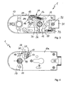
- FIG. 3 shows a further example of a lock 1 with an open lock housing 10, and in the lock housing 10, a pressure nut 11 is rotatably received.
- a spring element 17 is arranged, which is designed as a tension spring and which biases the adjusting nut 11 about the actuating axis 12 rotationally.
- the connection of the spring element 17 to the lock housing 10 comprises an adjustment unit 18. With the adjustment unit 18, the spring preload in the spring element 17 can be changed.
- the pusher 11 is shown in the zero position, so that a recorded in the pusher 11 door handle occupies a horizontal position.
- the adjusting unit 18 has a screw 19, which is connected to the spring element 17, so that upon rotation of the screw 19 about the axis of rotation 22, the spring bias in the spring element 17 is adjustable.
- the connection between the screw 19 and the spring element 17 comprises a driver element 20, in which the screw 19 is screwed.
- the screw 19 is received in a stationary manner in the lock housing 10, wherein the holding arrangement of the screw 19 in the receptacle 24 allows the rotational movement of the screw 19 about the rotation axis 22.
- the driver element 20 can be moved in the manner of a rider along the threaded shank of the screw 19, and the spring preload in the spring element 17 is continuously adjustable.
- the lock 1 can be placed on the surface of a glass door, wherein the lock housing 10 is laterally bounded by a side wall 21, and in the side wall 21, an opening 23 is introduced.
- the opening 23 is inserted in a position in the side wall 21, in which the rotation axis 22 extends approximately centrally through the opening 23 therethrough. Consequently, the screw 19 can be rotated with a tool about the axis of rotation 22, so that the adjustment of the spring bias is made possible by means of the adjusting unit 18 without opening the lock housing 10.
- the pressure nut 11 is rotationally biased about the actuating axis 12, and the pusher 11 serves to receive a door handle. If the door handle is actuated, a latch 31 can be pulled back into the lock housing 10.
- the latch 31 is attached to a latch shaft 33 by means of a mounting bolt 32, and the operative connection between the latch shaft 33 and the pusher 11 is formed by a slider 36.
- the axis of rotation 22 of the screw 19 is tapered to the side wall 21 of the lock housing 10 at an angle.
- the angle is determined such that a tool can be introduced through the opening 23 in order to be able to rotate the screw element 19 with the tool.
- the tapered arrangement of the axis of rotation 22 forms an adjustment of the driver element 20, through which the driver element 20 is adjustable at a distance from the follower 11, so that the spring bias of the spring element 17 can be changed accordingly.
- the angle of the rotation axis 22 to the side wall 21 of the lock housing 10 is dimensioned at about 45 °.
- through holes 30 are introduced into the lock housing 10, which is orthogonal by the lock housing 10 and by a not closer shown lock housing cover extend through and through the through holes 30 fasteners can be passed to place handle fittings on the lock housing 10 and on the lock housing cover. This allows a screw connection of handle fittings on the lock housing 10.
- the through holes 30 are inserted symmetrically to the actuating axis 12 in the lock housing 10 and in the lock housing cover, wherein the through holes in the lock housing 10 are aligned with the through holes in the lock housing cover.
- the through holes 30 may be arranged horizontally to accommodate standard pusher fittings.
- FIG. 4 shows a further embodiment of a lock 1, which is also designed to be arranged on a glass door.
- the lock housing 10 is shown with a lock housing cover 10a, which is broken in the region of the arrangement of the adjustment unit 18.
- the adjusting unit 18 in turn has a screw 19, which extends along a rotation axis 22, wherein the axis of rotation 22 to the side wall 21 of the lock housing 10 assumes a right angle.
- the screw 19 has a screw head which is seated in the side wall 21 and terminates approximately with the outside of the side wall 21.
- the pusher 11 is arranged on the side facing away from the lock latch 31 of the lock 1, and the bias of the spring element 17 on the Drückemuss 11 can be done by adjusting the Mifi interviewiatas 20 in the same manner by means of the adjusting unit 18, as already stated in the first embodiment.
- FIGS. 5a and 5b a lock with a lock housing 10 is shown.
- a follower 11 is rotatably received about an actuating axis 12.
- a lock housing cover 10 a is applied, wherein the lock housing cover 10 a shown broken in the region of a stop element 27 is.
- the pressure nut 11 has a lever arm 26 which serves to abut the stop element 27.
- the stop member 27 is formed as an adjusting screw 27, and the adjusting screw 27 is screwed into a screw receiving part 28 and extends approximately at right angles to the extension direction of the lever arm 26 along the screw axis.
- FIG. 5a shows the screw 27 in a first adjustment position in which the zero position of the follower 11 is adjusted in a counterclockwise direction.
- FIG. 5b the adjusting screw 27 is adjusted against the screw receiving part 28, and the zero position of the pressure nut 11 is adjusted in the clockwise direction.
- a limiting element 38 is mounted on the lock housing cover 10a, against which the head of the adjusting screw 27 can strike.
- an opening 39 is introduced in the lock housing 10, through which a tool for rotating the adjusting screw 27 can be inserted.
- the screw receiving part 28 is arranged in the lock housing 10, and for mounting the adjusting screw 27 can be screwed into the screw receiving part 28, while the lock housing cover 10a is not yet mounted, the adjusting screw 27 is screwed into the screw receiving part 28, then the lock housing cover 10a can be mounted, and the limiting element 38 limits a Ausschraubterrorism the screw 27 from the screw receiving part 28.
- the screwing of the screw 27 along the screw axis is limited on the one hand by the abutment of the screw head on the screw receiving part 28 and on the other hand by the abutment of the screw head to the limiting element 38.
- the opening 39 shown in the illustration is aligned with the screw axis, and is located on the lower side of the lock 1 with respect to the installation position.
- the screw receiving part 28 is shown as part of the lock housing 10, and the screw receiving part 28 also serves as a stop pin for the rotational movement of the follower 11 when it is rotated from the zero position clockwise about the actuating axis 12.
- FIGS. 6a to 6d show a latch 31 of a lock 1.
- the latch 31 has two strip-shaped plastic webs 34, protrude from the surface of the main body of the latch 31.
- the plastic webs 34 form the contact body for the contact of the latch 31 with a locking counterpart, for example with a strike plate.
- the plastic webs 34 can according to the illustrations in FIGS. 6a and 6b be arranged on the side edges of the lock latch 31 in the form of strip-shaped bands, or the plastic webs are according to the embodiments in the FIGS. 6c and 6d formed as plastic caps, which are attached to the side of the latch 31.
- FIG. 7 shows a further view of a lock housing 10 of a lock 1, and in the region of the latch guide for guiding the latch 31, the lock housing 10 has latch guide elements 35 which are formed as plastic elements and are used in the lock housing 10. If the lock latch 31 is mounted in the lock housing 10, the latch guide elements 35 form the contact bodies between the lock latch 31 and the lock housing 10 or the lock housing cover 10a.
Landscapes
- Engineering & Computer Science (AREA)
- Mechanical Engineering (AREA)
- Lock And Its Accessories (AREA)
- Hinges (AREA)
Abstract
Description
- Die vorliegende Erfindung betrifft ein Schloss für eine Ganzglastür, das auf der Oberfläche der Ganzglastür montierbar ist und, mit einem Schlossgehäuse, in dem eine Drückernuss um eine Betätigungsachse drehbar aufgenommen ist, wobei die Drückemuss eine Aufnahmeöffnung aufweist, in die ein Türdrückerschaft eines Türdrückers einführbar ist.
- Aus der
EP 1 049 845 B1 ist ein Schloss für eine Tür bekannt, das ein Schlossgehäuse aufweist, in dem eine Drückemuss um eine Betätigungsachse drehbar aufgenommen ist. Die Drückemuss weist eine Aufnahmeöffnung in Gestalt einer Vierkantöffnung auf, und in nicht näher gezeigter Weise kann in die Aufnahmeöffnung der Schaft eines Türdrückers eingeführt werden. Damit ist der Türdrücker, beispielsweise ausgeführt als Türklinke oder als Türknauf, mit der Drückemuss drehfest verbunden, und bei Betätigung des Türdrückers kann die Drückemuss um die Betätigungsachse verdreht werden, um das Schloss zu betätigen. Die Aufnahmeöffnung zur Aufnahme des Türdrückers weist eine quadratische Form auf, und wenigstens einer von zwei Türdrückern besitzt einen Türdrückerschaft, der durch die quadratische Aufnahmeöffnung hindurch geführt wird. Der Schaft des Türdrückers besitzt dabei eine Länge, die derart bemessen ist, dass der Schaft nach Durchführung durch die Drückernuss in einem zweiten, auf der gegenüberliegenden Türseite angeordneten Türdrücker hineingeführt und mit diesem verbunden werden kann. - Nachteilhafterweise ergibt sich ein Spiel zwischen dem Türdrückerschaft und der quadratischen Aufnahmeöffnung. Gewöhnlich wird die Passung zwischen dem Vierkantschaft des Türdrückers und der Aufnahmeöffnung als Spielpassung ausgeführt, um den Türdrückerschaft kraftfrei in die Aufnahmeöffnung einführen zu können. Insbesondere ist bekannt, dass Türdrücker und Drückemuss von verschiedenen Herstellern zu einem Schloss gefügt werden, und es können sich verschieden große Spielmaße ergeben. Daher ist es wünschenswert, die Montageanordnung des Türdrückers am Schloss zu verbessern.
- Es ist daher die Aufgabe der vorliegenden Erfindung, ein Schloss für eine Tür mit einer verbesserten Aufnahme eines Türdrückers zu schaffen, insbesondere ist es die Aufgabe der vorliegenden Erfindung, ein Spiel zwischen dem Türdrückerschaft und der Aufnahmeöffnung in der Drückernuss eines Schlosses zu vermeiden.
- Diese Aufgabe wird ausgehend von einem Schloss für eine Tür gemäß dem Oberbegriff des Anspruches 1 in Verbindung mit den kennzeichnenden Merkmalen gelöst. Vorteilhafte Weiterbildungen der Erfindung sind in den abhängigen Ansprüchen angegeben.
- Die Erfindung schließt die technische Lehre ein, dass in der Aufnahmeöffnung wenigstens ein Klemmelement angeordnet ist, das sich in den Montagebereich des Türdrückerschaftes des Türdrückers hinein erstreckt.
- Die Erfindung nutzt dabei die Möglichkeit, ein Klemmelement in der Aufnahmeöffnung derart anzuordnen, dass das Klemmelement den Türdrückerschaft des Türdrückers dann in der Aufnahmeöffnung verklemmt, wenn dieser in die Aufnahmeöffnung eingefügt wird. Das Klemmelement kann als federelastisches Metallelement, insbesondere als Blattfeder, ausgebildet sein, das sich mit einem Druckabschnitt in den Montagebereich des Türdrückerschaftes des Türdrückers hinein erstreckt. Durch die Anordnung des Klemmelementes wird der Vierkantschaft des Türdrückers gegen die dem Klemmelement gegenüberliegende Vierkantfläche in der Aufnahmeöffnung gepresst. Insbesondere können zwei Klemmelemente in zwei aneinander angrenzenden, rechtwinklig zueinander ausgeführten Vierkantflächen ausgebildet sein, und beim Fügen des Vierkantschaftes in der Vierkantöffnung muss lediglich die Kraft überwunden werden, die notwendig ist, um das oder die Klemmelemente aus dem Montagebereich des Vierkantschaftes zurückzudrücken. Ist der Vierkantschaft in der Vierkantöffnung eingefügt, wird das Spiel zwischen dem Vierkantschaft und der Vierkantöffnung durch das eine oder die beiden Klemmelement(e) herausgedrückt. Im Ergebnis ist eine spielfreie Anordnung eines Türdrückers in einer Drückemuss möglich, ohne das Passungsmaß zwischen dem Türdrückerschaft und der Vierkantöffnung mit geringeren Toleranzwerten auszugestalten.
- Vorteilhafterweise kann sich das Klemmelement insbesondere als blechförmiger Streifen etwa entlang der Betätigungsachse durch die Aufnahmeöffnung hindurch erstrecken, wobei das Klemmelement insbesondere über die Enden des blechförmigen Streifens an der Drückemuss verliersicher gehalten ist. Der Druckabschnitt, der sich in den Montagebereich des Türdrückerschaftes hinein erstreckt, ist zwischen den beiden Enden des blechförmigen Streifens gebildet, und der Druckabschnitt bildet eine Ausbuchtung, die federelastisch gegen die Vierkantfläche zurückgedrückt werden kann, an der das Klemmelement angeordnet ist. Die Breite des streifenförmigen Metallelementes kann der Breite der Vierkantfläche entsprechen oder die Breite des blechförmigen Streifens ist geringer als die Breite der Vierkantfläche und damit geringer als die Kantenlänge der Vierkantöffnung. Dadurch, dass das Klemmelement über seine Enden an der Drückemuss verliersicher gehalten ist, ist der mittlere Bereich, der den Druckabschnitt bildet, frei elastisch verformbar. Ist der vierkantförmige Türdrückerschaft in der Aufnahmeöffnung eingefügt, so wird durch das zurückfedernde Klemmelement dauerhaft eine Kraft und damit eine Verspannung zwischen der Vierkantöffnung und dem Vierkantschaft geschaffen.
- Die Drückemuss kann als metallisches Bauteil ausgebildet sein und eine flächige Erstreckung mit zwei sich gegenüberliegenden Planflächen aufweisen, und die Aufnahmeöffnung erstreckt sich orthogonal zu den Planflächen. Im Übergang zwischen der Aufnahmeöffnung in die Planflächen kann die Aufnahmeöffnung kragenförmige Abschnitte aufweisen, die über den Planflächen hervorstehen. Die Enden des Klemmelementes können zur klemmenden Anordnung des Klemmelementes in der Aufnahmeöffnung klammerartig um die kragenförmigen Abschnitte gebogen sein. Dadurch ergibt sich der fertigungstechnische Vorteil, das Klemmelement als federelastisches Metallelement auszuführen und somit als einen blechförmigen Streifen zu gestalten, der zur Anordnung in der Aufnahmeöffnung um die kragenförmigen Abschnitte herumgebogen, beispielsweise umgebördelt wird.
- Als besonders vorteilhafte Variante zur Anordnung des Klemmelementes hat sich gezeigt, dass das Klemmelement als klipsbares Element ausgeführt werden kann, das zur klemmenden Anordnung in die Aufnahmeöffnung einklipsbar ist. Die Endbereiche des Klemmelementes können klammerartig ausgeführt sein und nach außen gebogene Endstücke aufweisen, sodass das Klemmelement manuell in die Aufnahmeöffnung eingeführt werden kann und gegen die entsprechende Vierkantfläche gedrückt werden kann. Dabei schnappen die Enden des Klemmelementes um die kragenförmigen Abschnitte herum, und das Klemmelement ist selbsthaltend vor der Vierkantfläche in der Aufnahmeöffnung befestigt.
- Insbesondere kann dadurch eine leichte Hubbewegung der Enden des Klemmelementes über den kragenförmigen Abschnitten erfolgen, da bei einem Rückfedern des Druckabschnittes des Klemmelementes zwischen seinen Enden die Enden voneinander weggedrückt werden. Durch die Umklammerung der Enden des Klemmelementes um die kragenförmigen Abschnitte ist dennoch eine sichere Anordnung des Klemmelementes in der Aufnahmeöffnung ermöglicht. Dabei ist es von besonderem Vorteil, wenn das Klemmelement aus einem Federstahl ausgebildet ist, der eine Härte aufweist, die größer ist als die Härte des Werkstoffes der Drückernuss und/oder insbesondere größer ist als die Härte des Türdrückerschaftes.
- Die im Schlossgehäuse des Schlosses aufgenommene Drückernuss kann mit einem Federelement um die Betätigungsachse rotatorisch vorgespannt sein, so dass die Drückernuss in die Nulllage rückführbar ist, wenn der in der Drückernuss aufgenommene Türdrücker nicht betätigt wird. Das Federelement erstreckt sich zwischen einem Federangriffspunkt im Schlossgehäuse und einem Federarm an der Drückernuss. Der Federangriffspunkt kann eine Verstelleinheit umfassen, mit der die Federvorspannung im Federelement verstellbar ist. Die Verstelleinheit kann insbesondere ein Schraubelement aufweisen, das mit dem Federelement verbunden ist, so dass bei Verdrehung des Schraubelementes die Federvorspannung im Federelement verstellbar ist. Mit der Federvorspannung im Federelement kann die Kraft beziehungsweise das Moment um die Betätigungsachse in der Drückernuss verstellt werden. Das Schraubelement erstreckt sich entlang einer Drehachse, um die das Schraubelement verdreht werden kann, wobei die Drehachse in Richtung zur Drückernuss verlaufen kann. Das Schraubelement kann als Zylinderkopfschraube oder als Senkkopfschraube ausgeführt sein, und die Verbindung zwischen dem Schraubelement und dem Federelement erfolgt über den Gewindeschaft des Schraubelementes. Das Schraubelement ist dabei in einer festen Position, jedoch drehbar im Schlossgehäuse gelagert, und das dem Schraubelement zugewandte Ende des Federelementes kann bei Verdrehung des Schraubelementes entlang des Gewindeschaftes bewegt werden.
- Damit ist die Federvorspannung zwischen einem Minimalwert und einem Maximalwert stufenlos verstellbar. So kann die Nulllage der Drückernuss und folglich die des Türdrückers nachgestellt werden, da sich die Nulllage des Türdrückers beispielsweise beim Einrichten des Schlosses oder bei einem längeren Gebrauch des Schlosses verstellen kann. Gemäß einer vorteilhaften Ausgestaltung der Verstelleinheit kann die Verbindung zwischen dem Schraubelement und dem Federelement ein Mitnehmerelement aufweisen, in das das Schraubelement einschraubbar ist und an dem das der Drückemuss abgewandte Ende des Federelementes haltend angeordnet ist. Das Mitnehmerelement bildet einen Reiter, der eine Gewindebohrung aufweist, in die der Gewindeschaft des Schraubelementes einschraubbar ist. Wird das Schraubelement in Drehbewegung versetzt, so wird der Reiter zwischen der Position des Minimalwertes der Federvorspannung und der Position des Maximalwertes der Federvorspannung stufenlos verstellt. Der Minimalwert der Federvorspannung wird erreicht, wenn das Mitnehmerelement die der Drückernuss zugewandte Position einnimmt und der Maximalwert der Federvorspannung wird erreicht, wenn das Mitnehmerelement die der Drückemuss abgewandte Position einnimmt, Das Mitnehmerelement kann dabei in einer insbesondere im Schlossgehäuse eingebrachten Nut geführt sein, durch die der Verstellweg des Mitnehmerelementes auf den Verstellweg zwischen dem Minimalwert und dem Maximalwert der Federvorspannung begrenzt ist. Weiterhin wird durch die Führung des Mitnehmerelementes in der Nut erreicht, dass sich das Mitnehmerelement bei Verdrehung des Schraubelementes nicht mit dreht.
- Vorteilhafterweise weist das Schlossgehäuse eine Seitenwand auf, und die Drehachse des Schraubelementes durchstößt die Seitenwand, insbesondere durchstößt die Drehachse die Seitenwand senkrecht oder unter einem Winkel kleiner 90°, wobei ferner im Durchstoßbereich eine Öffnung in der Seitenwand eingebracht ist. Das Schlossgehäuse kann zur Anordnung auf der Oberfläche eines Glasflügels einer Glastür ausgebildet sein, wobei sich die Seitenwand senkrecht zur Oberfläche des Glasflügels erstreckt. Durch die Öffnung kann ein Werkzeug zur Drehung des Schraubelementes hindurchgeführt werden, oder das Schraubelement weist einen Schraubenkopf auf, der in der Öffnung sitzt. Befindet sich das Schlossgehäuse in einer montierten Anordnung auf der Oberfläche des Glasflügels, so kann das Schraubelement weiterhin mittels eines Werkzeuges in Drehbewegung versetzt werden, um die Federvorspannung des Federelementes zu verändern, ohne dass das Schloss demontiert werden muss oder ohne dass ein Deckel abgenommen werden muss. Das Werkzeug kann durch die Öffnung der Seitenwand des Schlossgehäuses hindurch eingeführt werden, um dieses in das Schraubelement einzusetzen. Das Werkzeug kann beispielsweise ein Schraubendreher oder ein Innensechskantschlüssel sein.
- Alternativ kann sich ein Schraubenkopf des Schraubelementes durch die Öffnung in der Seitenwand hindurch erstrecken oder an der Öffnung selbst angeordnet sein, um ein Schraubwerkzeug in den Schraubenkopf des Schraubelementes einzusetzen und dieses zu verdrehen. Mit weiterem Vorteil kann die Öffnung in der Seitenwand des Schlossgehäuses eingebracht sein, die in Bezug auf die Einbaulage des Schlossgehäuses nach unten weist, wodurch die Öffnung in der Seitenwand des Schlossgehäuses für einen Betrachter nicht direkt sichtbar ist und es wird verhindert, dass Verunreinigungen in die Öffnung eintreten können. Weiterführend kann ein Stopfen vorgesehen sein, der zum Verschluss der Öffnung dienen kann.
- Um das Schraubelement ortsfest im Schlossgehäuse anzuordnen, kann im Schlossgehäuse eine Aufnahme vorgesehen sein, die zur Aufnahme des Schraubelementes dient. Die Aufnahme des Schraubelementes erfolgt dabei derart, dass das Schraubelement weiterhin drehbar ist, ohne dass sich die Lage des Schraubelementes im Schlossgehäuse verändert. Beispielsweise kann die Aufnahme in Gestalt einer am Schlossgehäuse angegossenen oder aus einem Blechmaterial des Schlossgehäuses herausgebogenen Lasche ausgebildet sein, in der das Schraubelement aufgenommen wird.
- Das Federelement, das zwischen dem durch die Verstelleinheit verstellbaren Federangriffspunkt im Schlossgehäuse und dem Federarm der Drückemuss angeordnet ist, kann als Zugefeder ausgebildet sein, wobei alternativ das Federelement auch als Druckfeder ausgeführt sein kann. Ist das Federelement als Druckfeder ausgeführt, wird der Maximalwert der Federvorspannung dann erreicht, wenn das Mitnehmerelement in der dem Federarm zugewandten Position angeordnet ist, und der Minimalwert der Federvorspannung wird dann erreicht, wenn das Mitnehmerelement einen maximalen Abstand zum Federarm der Drückemuss aufweist. Die Verstelleinheit kann bei Ausbildung des Federelementes als Druckfeder auf gleiche Weise ausgestaltet sein.
- Weiterführend kann die Drückernuss einen Hebelarm aufweisen, wobei der Hebelarm zum Anschlag an ein Anschlagelement ausgebildet ist, und wobei das Anschlagelement insbesondere verstellbar ist, um die Nulllage eines in der Druckemuss aufnehmbaren Türdrückers einzustellen. Das Anschlagelement kann vorteilhafterweise als Stellschraube ausgebildet sein, die in einem Schraubenaufnahmeteil im Schlossgehäuse aufgenommen ist. Die Erstreckungsrichtung des Hebelarms und die Erstreckungsrichtung der Stellschraube können etwa einen rechten Winkel zueinander einnehmen, und wenn der Anschlagpunkt zwischen der Stellschraube und dem Hebelarm durch ein Verdrehen der Stellschraube im Schraubenaufnahmeteil verändert wird, kann die Nulllage des Türdrückers ebenfalls verändert werden. Das Federelement spannt dabei die Drückernuss um die Betätigungsachse der Drückemuss derart vor, dass der Hebelarm in der Nulllage der Drückemuss gegen das Schraubelement, insbesondere gegen das Ende des Gewindeschaftes des Schraubelementes, anschlägt. Abhängig von der Einschraubtiefe des Schraubelementes im Schraubenaufnahmeteil verlagert sich der Anschlagpunkt des Hebelarms gegen die Stellschraube, und die Nulllage der Drückernuss und folglich des Türdrückers kann verstellt werden.
- Im Hebelarm kann ein Prallelement eingebracht sein, gegen das das Anschlagelement anschlägt. Das Prallelement kann ein Material aufweisen, das vom Material des Hebelarms und folglich vom Material der Drückernuss abweicht. Beispielsweise kann das Prallelement aus einem Hartkunststoff gebildet sein, der in einer Aufnahme im Hebelarm eingesetzt wird. Damit wird der Vorteil erreicht, dass bei einem Anschlag des Hebelarms gegen das Anschlagelement eine Geräuschdämpfung erfolgt, und durch die Ausbildung des Prallelementes aus einem Hartkunststoff werden Deformationen in der Oberfläche des Prallelementes verhindert, insbesondere, wenn der Türdrücker durch die Vorspannung des Federelementes gegen das Anschlagelement zurückschnellt.
- Ist die Nulllage des Türdrückers eingestellt, kann das Anschlagelement mit einer chemischen Schraubensicherung versehen werden, so dass sich das Anschlagelement nicht selbsttätig verstellt, und die chemische Schraubensicherung kann beispielsweise ein Klebstoff sein. Insbesondere bei Ganzglastüren tritt der optische Effekt auf, dass bei nichtrechtwinkliger Lage des Türdrückers sein Spiegelbild und der durchscheinende Gegentürdrücker besonders hervortreten. Die Nulllagenverstellbarkeit ermöglicht es daher, das optische Gesamtbild der Türanordnung zu verbessem. Zum Verstellen des Anschlagelementes, insbesondere zum Verstellen der Stellschraube, kann im Schlossgehäuse eine Öffnung vorgesehen sein, durch die ein Werkzeug einführbar ist, um die Stellschraube in Drehbewegung zu versetzen und damit den Anschlagpunkt zwischen der Stellschraube und dem Hebelarm zu verändern.
- Das Schloss kann ein Schlossgehäuse aufweisen, das einen Grundkörper bildet, und auf dem Schlossgehäuse kann ein Schlossgehäusedeckel aufsetzbar sein, so dass ein geschlossener Aufnahmeraum zur Aufnahme der Schließmechanik, insbesondere zur Aufnahme der Türdrückernuss, gebildet wird. Vorteilhafterweise können seitlich zur Betätigungsachse zwei Durchgangslöcher vorgesehen sein, die sich durch das Schlossgehäuse und durch den Schlossgehäusedeckel hindurch erstrecken, und durch die Durchgangslöcher können Befestigungselemente hindurchgeführt werden, um Drückerbeschläge auf dem Schlossgehäuse beziehungsweise auf dem Schlossgehäusedeckel anzuordnen. Damit wird bei einem Schloss, das als Schloss für eine Ganzglastür ausgebildet ist, eine Durchverschraubung von Drückerbeschlägen ermöglicht. Die Durchgangslöcher können symmetrisch zur Betätigungsachse im Schlossgehäuse und im Schlossgehäusedeckel eingebracht sein, wobei die Durchgangslöcher im Schlossgehäuse mit den Durchgangslöchern im Schlossgehäusedeckel fluchten. In Bezug auf die Einbaulage des Schlosses können die Durchgangslöcher horizontal und seitlich zur Drückemuss angeordnet sein, um Standard-Drückerbeschläge aufnehmen zu können. Alternativ können die Durchgangslöcher diagonal angeordnet sein, und die Anordnung der Durchgangslöcher kann dem Standard der Drückerbeschläger angepasst sein. Folglich können weiterführend auch horizontal-oval geformte Durchgangslöcher vorgesehen sein, um Standard-Beschläge mit verschiedenen Stichmaßen oder mit verschiedenen Offset-Maßen verwenden zu können, Zur Aufnahme von Klemmkräften bei der Montage des Schlosses kann die Laibung der Durchgangslöcher als Stützhülse ausgebildet sein. Damit können standardmäßig Drückerrosetten mit DIN-Stichmaß mit 38mm eingesetzt werden. Bei normalen Schlössern werden Rosette und Gegenrosette miteinander verschraubt, was jedoch für Schlösser für Ganzglastüren bislang nicht möglich war. Durch die erfindungsgemäße Ausgestaltung der Durchgangslöcher im Schlossgehäuse beziehungsweise im Schlossgehäusedeckel eines Schlosses für eine Ganzglastür können folglich DIN-Drückerrosetten aufgesetzt und durch das Torblatt miteinander verschraubt werden.
- Das Schloss kann eine Schlossfalle aufweisen, die durch Drehung der Drückernuss um die Betätigungsachse zwischen einer aus dem Schlossgehäuse hervorspringenden und einer in das Schlossgehäuse zurückgezogenen Position bewegbar ist, wobei die Schlossfalle mittels einer Montageschraube an einem Fallenschaft montierbar ist, so dass die Schlossfalle in zwei 180° zueinander gedrehten Positionen am Fallenschaft montierbar ist. Mit Vorteil kann die Schlossfalle wenigstens einen streifenförmigen Kunststoffsteg aufweisen, wobei die Schlossfalle insbesondere zwei seitliche Kunststoffstege aufweisen kann, so dass wenigstens der eine und vorzugsweise beide Kunststoffstege den Kontaktkörper zum Kontakt der Schlossfalle mit einem Sperrgegenstück, beispielsweise mit einem Schließblech, bildet. Weiterführend kann die Schlossfalle Kunststoffstege aufweisen, die sich über der Schlossfalle in Richtung zum Fallenschafft hinweg erstrecken, um den Kontakt der Schlossfalle zur Führung im Schlossgehäuse durch die Kunststoffstege zu bilden. Weiterführend kann das Schlossgehäuse und/oder der Schlossgehäusedeckel Fallenführungselemente aufweisen, wobei die Fallenführungselemente vorzugsweise als in das Schlossgehäuse und/oder in den Schlossgehäusedeckel eingelassene Kunststoffdämpfungselemente ausgebildet sind, die den Kontaktkörper zwischen der Schlossfalle und dem Schlossgehäuse und/oder dem Schlossgehäusedeckel bilden.
- Ist die Schlossfalle in zwei 180° zueinander gedrehten Positionen am Fallenschaft montierbar, kann das Schloss sowohl für rechts als auch für links schließende Türen Verwendung finden, Insbesondere Ganzglastüren sind aufgrund der geringen Eigendämpfung des Türblattes besonders geräuschsensibel. Daher ist es wünschenswert, sämtliche Geräuschquellen zu eliminieren, so dass eine gedämpfte Anordnung der Schlossfalle im Schlossgehäuse eine einfache, wirkungsvolle Dämpfung bildet. Weist die Schlossfalle Kunststoffstege auf, die die Kontaktkörper zum Kontakt mit dem Sperrgegenstück bilden, kann eine weitere Dämpfung der Schlossfalle erreicht werden. Ein wesentlicher Geräuschfaktor ist das Aufschlaggeräusch der Schlossfalle auf das Sperrgegenstück, wodurch eine Schiebebewegung in die Schlossfalle eingeleitet wird. Durch die Dämpfung mittels der Kunststoffstege wird sowohl der Kontakt der Schlossfalle zum Sperrgegenstück als auch der Kontakt der Schlossfalle im Schlossgehäuse gedämpft.
- Das Schlossgehäuse kann weiterhin Fallenführungselemente aufweisen, die vorzugsweise als in das Schlossgehäuse eingelassene Kunststoffdämpfungselemente ausgebildet sind, die den Kontaktkörper zwischen der Schlossfalle und dem Schlossgehäuse bilden. Die Fallenführungselemente können aus verschleißfestem Kunststoff ausgebildet sein und einen kreisrunden Querschnitt aufweisen. Damit können die Fallenführungselemente gehäuseseitig in Sackbohrungen eingebracht und formschlüssig vom montierten Schlossgehäusedeckel gehalten werden. Die Fallenführungselemente können maßlich so ausgelegt und positioniert sein, dass im montierten Zustand eine Spielpassung zwischen der Schlossfalle und dem Schlossgehäuse entsteht. Insbesondere bei Aufschlagen der Schlossfalle auf das Sperrgegenstück entsteht eine leichte Kippbewegung der Schlossfalle um das Spiel zwischen der Schlossfalle und der Fallenführung. Dabei schlägt die Schlossfalle gegen das Schlossgehäuse und erzeugt ein zusätzliches Geräusch, welches durch die erfindungsgemäßen Kunststoffstege sowohl an der Schlossfalle als auch durch die Fallenführungselemente im Schlossgehäuse beziehungsweise im Schlossgehäusedeckel gedämpft wird.
- Weitere, die Erfindung verbessernde Maßnahmen werden nachstehend gemeinsam mit der Beschreibung bevorzugter Ausführungsbeispiele der Erfindung anhand der Figuren näher dargestellt. Es zeigt:
- Figur 1
- ein Ausführungsbeispiel einer Drückernuss in einer perspektivischen Ansicht mit den Merkmalen der vorliegenden Erfindung,
- Figur 2a-2b
- Ansichten der Drückernuss gemäß
Fig. 1 , - Figur 3
- ein erstes Ausführungsbeispiel eines Schlosses mit einer Verstelleinheit,
- Figur 4
- ein zweites Ausführungsbeispiel eines Schlosses mit einer weiteren Verstelleinheit,
- Figur 5a-5b
- ein Ausführungsbeispiel des Schlosses mit einer Drückernuss und einem verstellbaren Anschlagelement in zwei verschiedenen Verstellpositionen,
- Figur 6a-6d
- eine Schlossfalle mit erfindungsgemäß eingebrachten Kunststoffstegen in verschiedenen Ansichten und
- Figur 7
- ein Ausführungsbeispiel eines Schlossgehäuses für ein Schloss mit Fallenführungselementen.
- In den
Figuren 1, 2a und 2b ist eine Drückemuss 11 für ein Schloss mit den Merkmalen der Erfindung dargestellt, Die Drückemuss 11 kann im Schlossgehäuse des Schlosses um die Betätigungsachse 12 drehbar aufgenommen werden und weist eine Aufnahmeöffnung 13 auf, die als Vierkantöffnung ausgebildet ist und in der der Schaft eines Türdrückers eingeführt werden kann. Dadurch kann der Türdrücker verdrehfest mit der Drückemuss 11 verbunden werden. Die Drückemuss 11 besitzt einen Federarm 25, an dem ein Verbindungselement 37 in einem Abstand zur Betätigungsachse 12 angebracht ist. Das Verbindungselement 37 dient zur Verbindung des Federarms 25 mit einem Federelement, durch das über den Federarm 25 ein Moment um die Betätigungsachse 12 in die Drückemuss 11 eingeleitet wird. Damit kann die Drückemuss 11 in eine Nulllage rückgeführt werden, und die Drückemuss 11 weist ferner einen Hebelarm 26 auf, der gegen ein Anschlagelement zur Anlage gelangen kann. Endseitig im Hebelarm 26 ist ein Prallelement 29 eingebracht, und der Hebelarm 26 stößt mit dem Prallelement 29 gegen das Anschlagelement an. Die rotatorische Vorspannung, die über den Federarm 25 in die Drückemuss 11 um die Betätigungsachse 12 eingebracht wird, führt dazu, dass die Drückernuss 11 mit dem Hebelarm 26 und dem Prallelement 29 gegen das Anschlagelement gehalten wird, und durch diese Position ist die Nulllage der Drückernuss 11 gebildet. - In der Aufnahmeöffnung 13 ist erfindungsgemäß ein Klemmelement 14 eingebracht, das sich in den Montagebereich eines Türdrückerschaftes hinein erstreckt, und der Türdrückerschaft kann ebenfalls als Vierkantschaft ausgebildet sein, der mit einer Spielpassung in die ebenfalls viereckig ausgestaltete Aufnahmeöffnung 13 eingesetzt werden kann. Das Klemmelement 14 ist als federelastisches Metallelement ausgebildet, das einen Druckabschnitt 14a aufweist, der sich in den Montagebereich des Türdrückerschaftes des Türdrückers hinein erstreckt. Das Klemmelement 14 bildet einen blechförmigen Streifen, der sich entlang der Betätigungsachse 12 entlang erstreckt und an einer Vierkantfläche 15 der Aufnahmeöffnung 13 angebracht ist. Der Druckabschnitt 14a bildet eine Ausbuchtung des Klemmelementes 14 in den Montagebereich des Türdrückerschaftes hinein, und wenn der Türdrückerschaft in die Aufnahmeöffnung 13 eingeführt wird, wird der Druckabschnitt 14a in Richtung zur Vierkantfläche 15 zurückgedrückt. Dadurch entsteht eine federelastische Vorspannung im Klemmelement 14, und der Vierkantschaft des Türdrückers wird gegen die Vierkantfläche gedrückt, die der Vierkantfläche 15 gegenüber liegt, an der das Klemmelement 14 angeordnet ist. Beispielhaft ist in lediglich einer Vierkantftäche 15 in der Aufnahmeöffnung 13 ein Klemmelement 14 aufgenommen gezeigt, und mit besonderem Vorteil kann ein weiteres Klemmelement 14 auf einer weiteren Vierkantfläche 15a angeordnet sein, die an die Vierkantftäche 15 angrenzt.
- Die Drückernuss 11 weist einen plattenförmigen Grundkörper auf, und zu beiden Seiten des Grundkörpers erstrecken sich entlang der Betätigungsachse 12 kragenförmige Abschnitte 16. Um das Klemmelement 14 verliersicher in der Aufnahmeöffnung 13 anzuordnen, ist das Klemmelement 14 mit seinen Enden des streifenförmigen Körpers klammerartig um die kragenförmigen Abschnitte 16 herum gebogen. Damit ergibt sich eine fertigungstechnisch einfach umsetzbare Anordnung des Klemmelementes 14, und das Klemmelement 14 kann derart vorgebogen sein, dass sich der Druckabschnitt 14a zwischen den klammerartigen Enden in den Aufnahmebereich hinein erstreckt.
-
Figur 3 zeigt ein weiteres Beispiel eines Schlosses 1 mit einem geöffneten Schlossgehäuse 10, und im Schlossgehäuse 10 ist eine Drückemuss 11 drehbar aufgenommen. An der Drückernuss 11 ist ein Federelement 17 angeordnet, welche als Zugfeder ausgebildet ist und die die Verstellnuss 11 um die Betätigungsachse 12 rotatorisch vorspannt. Die Verbindung des Federelementes 17 zum Schlossgehäuse 10 umfasst eine Verstelleinheit 18. Mit der Verstelleinheit 18 kann die Federvorspannung im Federelement 17 verändert werden. Die Drückernuss 11 ist in der Nulllage dargestellt, so dass ein in der Drückernuss 11 aufgenommener Türdrücker eine horizontale Lage einnimmt. - Die Verstelleinheit 18 weist ein Schraubelement 19 auf, das mit dem Federelement 17 verbunden ist, so dass bei Verdrehung des Schraubelementes 19 um die Drehachse 22 die Federvorspannung im Federelement 17 verstellbar ist. Die Verbindung zwischen dem Schraubelement 19 und dem Federelement 17 umfasst ein Mitnehmerelement 20, in das das Schraubelement 19 eingeschraubt ist. Vermittels der Aufnahme 24 ist das Schraubelement 19 ortsfest im Schlossgehäuse 10 aufgenommen, wobei die haltende Anordnung des Schraubelementes 19 in der Aufnahme 24 die Drehbewegung des Schraubelementes 19 um die Drehachse 22 erlaubt. Damit kann das Mitnehmerelement 20 nach Art eines Reiters entlang des Gewindeschaftes des Schraubelementes 19 verfahren werden, und die Federvorspannung im Federelement 17 ist stufenlos verstellbar.
- Das Schloss 1 kann auf der Oberfläche einer Ganzglastür aufgesetzt werden, wobei das Schlossgehäuse 10 seitlich durch eine Seitenwand 21 berandet ist, und in der Seitenwand 21 ist eine Öffnung 23 eingebracht. Die Öffnung 23 ist in einer Position in der Seitenwand 21 eingebracht, in der sich die Drehachse 22 etwa mittig durch die Öffnung 23 hindurch erstreckt. Folglich kann das Schraubelement 19 mit einem Werkzeug um die Drehachse 22 verdreht werden, so dass die Verstellung der Federvorspannung mittels der Verstelleinheit 18 ermöglicht ist, ohne das Schlossgehäuse 10 zu öffnen.
- Durch das Federelement 17 wird die Drückemuss 11 um die Betätigungsachse 12 rotatorisch vorgespannt, und die Drückernuss 11 dient zur Aufnahme eines Türdrückers. Wird der Türdrücker betätigt, kann eine Schlossfalle 31 in das Schlossgehäuse 10 zurückgezogen werden. Die Schlossfalle 31 ist mittels einer Montageschraube 32 an einem Fallenschaft 33 angebracht, und die Wirkverbindung zwischen dem Fallenschaft 33 und der Drückernuss 11 wird über einen Schieber 36 gebildet.
- Die Drehachse 22 des Schraubelementes 19 ist zur Seitenwand 21 des Schlossgehäuses 10 unter einem Winkel angeschrägt. Der Winkel ist derart bestimmt, dass durch die Öffnung 23 ein Werkzeug eingeführt werden kann, um mit dem Werkzeug das Schraubelement 19 verdrehen zu können. Zugleich bildet die angeschrägte Anordnung der Drehachse 22 eine Verstellrichtung des Mitnehmerelementes 20, durch die das Mitnehmerelement 20 im Abstand zur Drückernuss 11 verstellbar ist, so dass die Federvorspannung des Federelementes 17 entsprechend verändert werden kann. Beispielsweise ist der Winkel der Drehachse 22 zur Seitenwand 21 des Schlossgehäuses 10 mit etwa 45° bemessen.
- Seitlich zur Aufnahme der Drückernuss 11 um die Betätigungsachse 12 sind Durchgangslöcher 30 in das Schlossgehäuse 10 eingebracht, die sich orthogonal durch das Schlossgehäuse 10 und durch einen nicht näher gezeigten Schlossgehäusedeckel hindurch erstrecken, und durch die Durchgangslöcher 30 können Befestigungselemente hindurchgeführt werden, um Drückerbeschläge auf dem Schlossgehäuse 10 bzw. auf dem Schlossgehäusedeckel anzuordnen. Damit wird eine Durchverschraubung von Drückerbeschlägen auf dem Schlossgehäuse 10 ermöglicht. Die Durchgangslöcher 30 sind symmetrisch zur Betätigungsachse 12 im Schlossgehäuse 10 und im Schlossgehäusedeckel eingebracht, wobei die Durchgangslöcher im Schlossgehäuse 10 mit den Durchgangslöchem im Schlossgehäusedeckel fluchten. In Bezug auf die Einbaulage des Schlosses 1 können die Durchgangslöcher 30 horizontal angeordnet sein, um Standard-Drückerbeschläge aufnehmen zu können.
-
Figur 4 zeigt ein weiteres Ausführungsbeispiel eines Schlosses 1, das ebenfalls zur Anordnung an einer Ganzglastür ausgebildet ist. Das Schlossgehäuse 10 ist mit einem Schlossgehäusedeckel 10a gezeigt, das im Bereich der Anordnung der Verstelleinheit 18 aufgebrochen ist. Die Verstelleinheit 18 weist wiederum ein Schraubelement 19 auf, das sich entlang einer Drehachse 22 erstreckt, wobei die Drehachse 22 zur Seitenwand 21 des Schlossgehäuses 10 einen rechten Winkel einnimmt. Das Schraubelement 19 besitzt einen Schraubenkopf, der in der Seitenwand 21 einsitzt, und etwa mit der Außenseite der Seitenwand 21 abschließt. Die Drückernuss 11 ist auf der der Schlossfalle 31 abgewandten Seite des Schlosses 1 angeordnet, und die Vorspannung des Federelementes 17 an der Drückemuss 11 kann durch die Verstellung des Mifinehmerelementes 20 auf gleiche Weise mittels der Verstelleinheit 18 erfolgen, wie bereits im ersten Ausführungsbeispiel dargelegt. - In den
Figuren 5a und 5b ist ein Schloss mit einem Schlossgehäuse 10 dargestellt. Im Schlossgehäuse 10 ist eine Drückernuss 11 drehbar um eine Betätigungsachse 12 aufgenommen. Auf dem Schlossgehäuse 10 ist ein Schlossgehäusedeckel 10a aufgebracht, wobei der Schlossgehäusedeckel 10a im Bereich eines Anschlagelementes 27 aufgebrochen gezeigt ist. Die Drückemuss 11 weist einen Hebelarm 26 auf, der zum Anschlag an das Anschlagelement 27 dient. Das Anschlagelement 27 ist als eine Stellschraube 27 ausgebildet, und die Stellschraube 27 ist in einem Schraubenaufnahmeteil 28 eingeschraubt und erstreckt sich etwa rechtwinklig zur Erstreckungsrichtung des Hebelarms 26 entlang der Schraubenachse. Wird die Stellschraube 27 in das Schraubenaufnahmeteil 28 eingeschraubt, so wird der Anschlag der Drückemuss 11 im Uhrzeigersinn verstellt, und wird die Stellschraube 27 aus dem Schraubenaufnahmeteil 28 herausgeschraubt, so wird der Anschlag der Drückemuss entgegen dem Uhrzeigersinn verstellt:Figur 5a zeigt die Stellschraube 27 in einer ersten Verstellposition, in der die Nulllage der Drückernuss 11 in einer Richtung entgegen dem Uhrzeigersinn verstellt ist. InFigur 5b ist die Stellschraube 27 gegen das Schraubenaufnahmeteil 28 verstellt, und Nulllage der Drückemuss 11 ist in Richtung des Uhrzeigersinns verstellt. - Um zu vermeiden, dass die Stellschraube 27 zu weit aus dem Schraubenaufnahmeteil 28 herausgeschraubt wird, ist am Schlossgehäusedeckel 10a ein Begrenzungselement 38 angebracht, gegen das der Kopf der Stellschraube 27 anschlagen kann. Um die Stellschraube 27 in Drehbewegung versetzen zu können, ist im Schlossgehäuse 10 eine Öffnung 39 eingebracht, durch die ein Werkzeug zum Verdrehen der Stellschraube 27 eingeführt werden kann. Der Schraubenaufnahmeteil 28 ist im Schlossgehäuse 10 angeordnet, und zur Montage kann die Stellschraube 27 in den Schraubenaufnahmeteil 28 eingeschraubt werden, während der Schlossgehäusedeckel 10a noch nicht montiert ist, Ist die Stellschraube 27 im Schraubenaufnahmeteil 28 eingeschraubt, kann anschließend der Schlossgehäusedeckel 10a montiert werden, und das Begrenzungselement 38 begrenzt eine Ausschraubbewegung der Stellschraube 27 aus dem Schraubenaufnahmeteil 28. Damit wird die Schraubbewegung der Stellschraube 27 entlang der Schraubenachse einerseits begrenzt durch das Angrenzen des Schraubenkopfes am Schraubenaufnahmeteil 28 und andererseits durch das Angrenzen des Schraubenkopfes an das Begrenzungselement 38. Die in der Darstellung gezeigte Öffnung 39 fluchtet mit der Schraubenachse, und befindet sich auf der unteren Seite des Schlosses 1 in Bezug auf die Einbaulage. Ferner ist der Schraubenaufnahmeteil 28 als Bestandteil des Schlossgehäuses 10 gezeigt, und der Schraubenaufnahmeteil 28 dient zugleich als Anschlagzapfen für die Drehbewegung der Drückernuss 11, wenn diese aus der Nulllage heraus im Uhrzeigersinn um die Betätigungsachse 12 verdreht wird.
- Die
Figuren 6a bis 6d zeigen eine Schlossfalle 31 eines Schlosses 1. Die Schlossfalle 31 weist zwei streifenförmige Kunststoffstege 34 auf, aus der Oberfläche des Grundkörpers der Schlossfalle 31 hervorstehen. Damit bilden die Kunststoffstege 34 die Kontaktkörper zum Kontakt der Schlossfalle 31 mit einem Sperrgegenstück, beispielsweise mit einem Schließblech. Die Kunststoffstege 34 können gemäß den Darstellungen inFigur 6a und 6b an den Seitenkanten der Schlossfalle 31 in Form von streifenförmigen Bändern angeordnet sein, oder die Kunststoffstege sind gemäß den Ausführungsbeispielen in denFiguren 6c und 6d als Kunststoffkappen ausgebildet, die seitlich an die Schlossfalle 31 angebracht sind. -
Figur 7 zeigt eine weitere Ansicht eines Schlossgehäuses 10 eines Schlosses 1, und im Bereich der Fallenführung zur Führung der Schlossfalle 31 besitzt das Schlossgehäuse 10 Fallenführungselemente 35, die als Kunststoffelemente ausgebildet sind und im Schlossgehäuse 10 eingesetzt sind. Wird die Schlossfalle 31 im Schlossgehäuse 10 montiert, so bilden die Fallenführungselemente 35 die Kontaktkörper zwischen der Schlossfalle 31 und dem Schlossgehäuse 10 bzw. dem Schlossgehäusedeckel 10a. - Die Erfindung beschränkt sich in ihrer Ausführung nicht auf die vorstehend angegebenen, bevorzugten Ausführungsbeispiele. Vielmehr ist eine Anzahl von Varianten denkbar, welche von der dargestellten Lösung auch bei grundsätzlich anders gearteten Ausführungen Gebrauch macht. Sämtliche aus den Ansprüchen, der Beschreibung oder den Zeichnungen hervorgehenden Merkmale und/oder Vorteile, einschließlich konstruktiver Einzelheiten oder räumlicher Anordnungen, können sowohl für sich als auch in den verschiedensten Kombinationen erfindungswesentlich sein.
-
- 1
- Schloss
- 10
- Schlossgehäuse
- 10a
- Schlossgehäusedeckel
- 11
- Drückernuss
- 12
- Betätigungsachse
- 13
- Aufnahmeöffnung
- 14
- Klemmelement
- 14a
- Druckabschnitt
- 15
- Vierkantfläche
- 16
- kragenförmiger Abschnitt
- 17
- Federelement
- 18
- Verstelleinheit
- 19
- Schraubabschnitt
- 20
- Mitnehmerelement
- 21
- Seitenwand
- 22
- Drehachse
- 23
- Öffnung
- 24
- Aufnahme
- 25
- Federarm
- 26
- Hebelarm
- 27
- Anschlagelement
- 28
- Schraubenaufnahmeteil
- 29
- Prallelement
- 30
- Durchgangsloch
- 31
- Schlossfalle
- 32
- Montageschraube
- 33
- Fallenschaft
- 34
- Kunststoffsteg
- 35
- Fallenführungselement
- 36
- Schieber
- 37
- Verbindungselement
- 38
- Begrenzungselement
- 39
- Öffnung
Claims (21)
- Schloss (1) für eine Ganzglastür mit einem Schlossgehäuse (10), das auf der Oberfläche der Ganzglastür montierbar ist und in dem eine Drückemuss (11) um eine Betätigungsachse (12) drehbar aufgenommen ist, wobei die Drückernuss (11) eine Aufnahmeöffnung (13) aufweist, in die ein Türdrückerschaft eines Türdrückers einführbar ist, dadurch gekennzeichnet, dass in der Aufnahmeöffnung (13) wenigstens ein Klemmelement (14) angeordnet ist, das sich in den Montagebereich des Türdrückerschaftes des Türdrückers hinein erstreckt
- Schloss (1) nach Anspruch 1, dadurch gekennzeichnet, dass das Klemmelement (14) als federelastisches Metallelement, insbesondere als Blattfeder, ausgebildet ist, das sich mit einem Druckabschnitt (14a) in den Montagebereich des Türdrückerschaftes des Türdrückers hinein erstreckt.
- Schloss (1) nach Anspruch 1 oder 2, dadurch gekennzeichnet, dass die Aufnahmeöffnung (13) als Vierkantöffnung ausgebildet ist, wobei das Klemmelement (14) in wenigstens einer Vierkantfläche (15) der Aufnahmeöffnung (13) eingebracht ist.
- Schloss (1) nach einem der Ansprüche 1 bis 3, dadurch gekennzeichnet, dass sich das Klemmelement (14) insbesondere als blechförmiger Streifen etwa entlang der Betätigungsachse (12) durch die Aufnahmeöffnung (13) hindurch erstreckt, wobei das Klemmelement (14) insbesondere über die Enden des blechförmigen Streifens an der Drückernuss (11) verliersicher gehalten ist.
- Schloss (1) nach einem der vorgenannten Ansprüche, dadurch gekennzeichnet, dass die Aufnahmeöffnung (13) im Übergang in die sich gegenüberliegenden Planflächen kragenförmige Abschnitte (16) aufweist, und die Enden des Klemmelementes (14) sind zur klemmenden Anordnung des Klemmelementes (14) in der Aufnahmeöffnung (13) klammerartig um die kragenförmigen Abschnitte (16) gebogen.
- Schloss (1) nach einem der vorgenannten Ansprüche, dadurch gekennzeichnet, dass das Klemmelement (14) als klipsbares Element ausgeführt ist, das zur klemmenden Anordnung in die Aufnahmeöffnung (13) einklipsbar ist.
- Schloss (1) nach einem der vorgenannten Ansprüche, dadurch gekennzeichnet, dass ein Federelement (17) vorgesehen ist, mit dem die Drückemuss (11) in der Drehposition um die Betätigungsachse (12) gegen eine Nulllage rückführbar ist, wobei eine Verstelleinheit (18) vorgesehen ist, mit der die Federvorspannung im Federelement (17) verstellbar ist.
- Schloss (1) nach Anspruch 7, dadurch gekennzeichnet, dass die Verstelleinheit (18) ein Schraubelement (19) aufweist, das mit dem Federelement (17) verbunden ist, sodass bei Verdrehung des Schraubelementes (19) die Federvorspannung im Federelement (17) verstellbar ist.
- Schloss (1) nach Anspruch 8, dadurch gekennzeichnet, dass die Verbindung zwischen dem Schraubelement (19) und dem Federelement (17) ein Mitnehmerelement (20) aufweist, in das das Schraubelement (19) einschraubbar ist und an dem das der Drückernuss (11) abgewandte Ende des Federelementes (17) haltend angeordnet ist.
- Schloss (1) nach einem der vorgenannten Ansprüche, dadurch gekennzeichnet, dass das Schlossgehäuse (10) eine Seitenwand (21) aufweist, und die Drehachse (22) des Schraubelementes (19) durchstößt die Seitenwand (21), insbesondere durchstößt die Drehachse (22) die Seitenwand (21) senkrecht oder unter einem Winkel kleiner 90°, wobei ferner im Durchstoßbereich eine Öffnung (23) in der Seitenwand (21) eingebracht ist.
- Schloss (1) nach Anspruch 10, dadurch gekennzeichnet, dass das Schlossgehäuse (10) zur Anordnung auf der Oberfläche eines Glasflügels einer Ganzglastür ausgebildet ist, wobei sich die Seitenwand (21) senkrecht zur Oberfläche des Glasflügels erstreckt.
- Schloss (1) nach einem der Ansprüche 8 bis 11, dadurch gekennzeichnet, dass das Schraubelement (19) an einer am Schlossgehäuse (10) angeordneten Aufnahme (24) aufgenommen ist.
- Schloss (1) nach einem der vorgenannten Ansprüche, dadurch gekennzeichnet, dass die Drückemuss (11) einen Federarm (25) aufweist, an dem das Federelement (17) mit dem der Verstelleinheit (18) abgewandten Ende angeordnet ist.
- Schloss (1) nach einem der vorgenannten Ansprüche, dadurch gekennzeichnet, dass die Drückemuss (11) einen Hebelarm (26) aufweist, wobei der Hebelarm (26) zum Anschlag an ein Anschlagelement (27) ausgebildet ist, wobei das Anschlagelement (27) insbesondere verstellbar ist, um die Nulllage eines in der Drückernuss (11) aufnehmbaren Türdrückers einzustellen.
- Schloss (1) nach Anspruch 14, dadurch gekennzeichnet, dass das Anschlagelement (27) als Stellschraube (27) ausgebildet ist, die vorzugsweise in einem Schraubenaufnahmeteil (28) im Schlossgehäuse (10) aufgenommen ist.
- Schloss (1) nach Anspruch 14 oder 15, dadurch gekennzeichnet, dass im Hebelarm (26) ein Prallelement (29) eingebracht ist, gegen das das Anschlagelement (27) anschlägt.
- Schloss (1) nach einem der vorgenannten Ansprüche, dadurch gekennzeichnet, dass seitlich zur Betätigungsachse (12) zwei Durchgangslöcher (30) vorgesehen sind, die sich durch das Schlossgehäuse (10) und durch den Schlossgehäusedeckel (10a) hindurch erstrecken, wobei durch die Durchgangslöcher (30) Befestigungselemente hindurchführbar sind, um Drückerbeschläge auf dem Schlossgehäuse (10) bzw. auf dem Schlossgehäusedeckel (10a) anzuordnen, insbesondere miteinander zu verschrauben.
- Schloss (1) nach einem der vorgenannten Ansprüche, dadurch gekennzeichnet, dass das Schloss (1) eine Schlossfalle (31) aufweist, die durch Drehung der Drückemuss (11) um die Betätigungsachse (12) zwischen einer aus dem Schlossgehäuse (10) hervorspringenden und einer in das Schlossgehäuse (10) zurückgezogenen Position bewegbar ist, wobei die Schlossfalle (31) mittels einer Montageschraube (32) an einem Fallenschaft (33) montierbar ist, sodass die Schlossfalle (31) in zwei 180° zueinander gedrehten Positionen am Fallenschaft (33) montierbar ist.
- Schloss (1) nach Anspruch 18, dadurch gekennzeichnet, dass die Schlossfalle (31) wenigstens einen streifenförmigen Kunststoffsteg (34) aufweist, insbesondere dass die Schlossfalle (31) zwei seitliche Kunststoffstege (34) aufweist, wobei der wenigstens eine Kunststoffsteg (34) den Kontaktkörper zum Kontakt der Schlossfalle (31) mit einem Sperrgegenstück bildet.
- Schloss (1) nach Anspruch 19, dadurch gekennzeichnet, dass sich die Kunststoffstege (34) über der Schlossfalle (31) in Richtung zum Fallenschaft (33) hinweg erstrecken, um den Kontakt der Schlossfalle (31) zur Führung im Schlossgehäuse (10) durch die Kunststoffstege (34) zu bilden.
- Schloss (1) nach Anspruch 18 bis 20, dadurch gekennzeichnet, dass das Schlossgehäuse (10) und/oder der Schlossgehäusedeckel (10a) Fallenführungselemente (35) aufweist, wobei die Fallenführungselemente (35) vorzugsweise als in das Schlossgehäuse (10) und/oder in den Schlossgehäusedeckel (10a) eingelassene Kunststoffdämpfungselemente ausgebildet sind, die den Kontaktkörper zwischen der Schlossfalle (31) und dem Schlossgehäuse (10) und/oder dem Schlossgehäusedeckel (10a) bilden.
Applications Claiming Priority (1)
| Application Number | Priority Date | Filing Date | Title |
|---|---|---|---|
| DE102010061522A DE102010061522A1 (de) | 2010-12-23 | 2010-12-23 | Schloss für eine Tür mit einer verbesserten Aufnahme eines Türdrückers |
Publications (2)
| Publication Number | Publication Date |
|---|---|
| EP2468990A2 true EP2468990A2 (de) | 2012-06-27 |
| EP2468990A3 EP2468990A3 (de) | 2015-07-01 |
Family
ID=45062788
Family Applications (1)
| Application Number | Title | Priority Date | Filing Date |
|---|---|---|---|
| EP11009172.5A Withdrawn EP2468990A3 (de) | 2010-12-23 | 2011-11-18 | Schloss für eine Ganzglastür |
Country Status (2)
| Country | Link |
|---|---|
| EP (1) | EP2468990A3 (de) |
| DE (1) | DE102010061522A1 (de) |
Citations (1)
| Publication number | Priority date | Publication date | Assignee | Title |
|---|---|---|---|---|
| EP1049845B1 (de) | 1998-08-28 | 2004-12-01 | DORMA GmbH + Co. KG | Schloss mit einem aus schlossgehäuse herausragendem fallenriegel |
Family Cites Families (4)
| Publication number | Priority date | Publication date | Assignee | Title |
|---|---|---|---|---|
| GB500992A (en) * | 1937-11-23 | 1939-02-20 | Legge And Company Ltd J | Improvements in followers for operating latch bolts and other bolts |
| DE1178736B (de) * | 1963-03-22 | 1964-09-24 | Hans Bruegemann | Schlossnuss |
| DE102008021002A1 (de) * | 2008-04-25 | 2009-10-29 | Ceslocks Gmbh | Schlosseinsatz für ein Glastürschloss |
| DE202009002001U1 (de) * | 2009-03-27 | 2010-08-12 | Schulte-Schlagbaum Aktiengesellschaft | Schloss mit verstellbarem Drückeranschlag |
-
2010
- 2010-12-23 DE DE102010061522A patent/DE102010061522A1/de not_active Withdrawn
-
2011
- 2011-11-18 EP EP11009172.5A patent/EP2468990A3/de not_active Withdrawn
Patent Citations (1)
| Publication number | Priority date | Publication date | Assignee | Title |
|---|---|---|---|---|
| EP1049845B1 (de) | 1998-08-28 | 2004-12-01 | DORMA GmbH + Co. KG | Schloss mit einem aus schlossgehäuse herausragendem fallenriegel |
Also Published As
| Publication number | Publication date |
|---|---|
| EP2468990A3 (de) | 2015-07-01 |
| DE102010061522A1 (de) | 2012-06-28 |
Similar Documents
| Publication | Publication Date | Title |
|---|---|---|
| EP2468989B1 (de) | Schloss für eine ganzglastür | |
| WO2009003600A1 (de) | Betätigungshandhabe für eine tür | |
| EP1723300B1 (de) | Verschluss mit Dreh- oder Klappriegel und Riegelverstelleinrichtung | |
| EP2439361B1 (de) | Schlosseinrichtung für insbesondere Türen | |
| EP2347073B1 (de) | Band für türen, fenster und dergleichen | |
| EP2468988A2 (de) | Schloss mit einer Nulllagenverstellung des Türdrückers | |
| DE102019113334B4 (de) | Beschlaganordnung | |
| EP3973126B1 (de) | Möbelbeschlag | |
| EP2113624B1 (de) | Tür- oder Fenstersicherungsvorrichtung | |
| EP2149664B1 (de) | Unterkonstruktion für ein Scharnierband und Scharnierband mit einer solchen Unterkonstruktion zur Befestigung an einem Türblatt | |
| EP2084356B1 (de) | Bandanordnung für türen, fenster oder dergleichen | |
| WO2007087945A1 (de) | Bandanordnung zur scharniergelenkigen verbindung eines flügels einer tür, eines fensters oder dergleichen, an einem rahmen | |
| EP2099989B1 (de) | Treibstangengetriebe | |
| EP2468990A2 (de) | Schloss für eine Ganzglastür | |
| EP1757759B1 (de) | Beschlagteil für einen Treibstangenbeschlag | |
| EP0930410B1 (de) | Betätigungshandhabe | |
| EP2132391B1 (de) | Treibstangenanordnung mit mindestens einer treibstange und mindestens einem treibstangenführungselement | |
| EP1922467B1 (de) | Band für türen, fenster oder dergleichen | |
| EP0913546B1 (de) | Getriebebeschlag für einen Flügelrahmen | |
| DE19507481C1 (de) | Abschließbarer Fenstergriff | |
| CH687406A5 (de) | Einsteckschloss fuer eine Tuer. | |
| EP4030021B1 (de) | Betätigungshandhabe für rosettenlose fenster und türen | |
| DE202005012246U1 (de) | Bandanordnung für Türen, Fenster o.dgl. | |
| EP1767736B1 (de) | Verstellbare Flügelanzugsvorrichtung | |
| EP2754797A2 (de) | Panik-Beschlag für einen Panikgriff oder eine Panikstange |
Legal Events
| Date | Code | Title | Description |
|---|---|---|---|
| AK | Designated contracting states |
Kind code of ref document: A2 Designated state(s): AL AT BE BG CH CY CZ DE DK EE ES FI FR GB GR HR HU IE IS IT LI LT LU LV MC MK MT NL NO PL PT RO RS SE SI SK SM TR |
|
| AX | Request for extension of the european patent |
Extension state: BA ME |
|
| PUAI | Public reference made under article 153(3) epc to a published international application that has entered the european phase |
Free format text: ORIGINAL CODE: 0009012 |
|
| RAP1 | Party data changed (applicant data changed or rights of an application transferred) |
Owner name: DORMA DEUTSCHLAND GMBH |
|
| PUAL | Search report despatched |
Free format text: ORIGINAL CODE: 0009013 |
|
| AK | Designated contracting states |
Kind code of ref document: A3 Designated state(s): AL AT BE BG CH CY CZ DE DK EE ES FI FR GB GR HR HU IE IS IT LI LT LU LV MC MK MT NL NO PL PT RO RS SE SI SK SM TR |
|
| AX | Request for extension of the european patent |
Extension state: BA ME |
|
| RIC1 | Information provided on ipc code assigned before grant |
Ipc: E05C 1/16 20060101ALN20150526BHEP Ipc: E05B 3/08 20060101ALI20150526BHEP Ipc: E05B 63/00 20060101ALN20150526BHEP Ipc: E05B 15/10 20060101ALN20150526BHEP Ipc: E05B 65/00 20060101AFI20150526BHEP Ipc: E05B 63/04 20060101ALN20150526BHEP Ipc: E05B 15/00 20060101ALI20150526BHEP Ipc: E05B 17/00 20060101ALN20150526BHEP Ipc: E05B 15/04 20060101ALN20150526BHEP |
|
| 17P | Request for examination filed |
Effective date: 20151209 |
|
| RBV | Designated contracting states (corrected) |
Designated state(s): AL AT BE BG CH CY CZ DE DK EE ES FI FR GB GR HR HU IE IS IT LI LT LU LV MC MK MT NL NO PL PT RO RS SE SI SK SM TR |
|
| RAP1 | Party data changed (applicant data changed or rights of an application transferred) |
Owner name: DORMAKABA DEUTSCHLAND GMBH |
|
| STAA | Information on the status of an ep patent application or granted ep patent |
Free format text: STATUS: EXAMINATION IS IN PROGRESS |
|
| 17Q | First examination report despatched |
Effective date: 20180328 |
|
| STAA | Information on the status of an ep patent application or granted ep patent |
Free format text: STATUS: THE APPLICATION IS DEEMED TO BE WITHDRAWN |
|
| 18D | Application deemed to be withdrawn |
Effective date: 20180808 |