EP2084356B1 - Bandanordnung für türen, fenster oder dergleichen - Google Patents
Bandanordnung für türen, fenster oder dergleichen Download PDFInfo
- Publication number
- EP2084356B1 EP2084356B1 EP07801946.0A EP07801946A EP2084356B1 EP 2084356 B1 EP2084356 B1 EP 2084356B1 EP 07801946 A EP07801946 A EP 07801946A EP 2084356 B1 EP2084356 B1 EP 2084356B1
- Authority
- EP
- European Patent Office
- Prior art keywords
- guide
- threaded extension
- hinge arrangement
- arrangement according
- fastening
- Prior art date
- Legal status (The legal status is an assumption and is not a legal conclusion. Google has not performed a legal analysis and makes no representation as to the accuracy of the status listed.)
- Active
Links
- 230000000295 complement effect Effects 0.000 claims description 8
- 230000000694 effects Effects 0.000 claims description 3
- 240000006829 Ficus sundaica Species 0.000 description 2
- 230000003750 conditioning effect Effects 0.000 description 2
- 238000004519 manufacturing process Methods 0.000 description 2
- 238000007789 sealing Methods 0.000 description 2
- 238000010276 construction Methods 0.000 description 1
- 238000005553 drilling Methods 0.000 description 1
- 238000003780 insertion Methods 0.000 description 1
- 230000037431 insertion Effects 0.000 description 1
- 238000002360 preparation method Methods 0.000 description 1
- 238000010079 rubber tapping Methods 0.000 description 1
Images

Classifications
-
- E—FIXED CONSTRUCTIONS
- E05—LOCKS; KEYS; WINDOW OR DOOR FITTINGS; SAFES
- E05D—HINGES OR SUSPENSION DEVICES FOR DOORS, WINDOWS OR WINGS
- E05D5/00—Construction of single parts, e.g. the parts for attachment
- E05D5/02—Parts for attachment, e.g. flaps
- E05D5/0215—Parts for attachment, e.g. flaps for attachment to profile members or the like
- E05D5/0223—Parts for attachment, e.g. flaps for attachment to profile members or the like with parts, e.g. screws, extending through the profile wall or engaging profile grooves
- E05D5/0238—Parts for attachment, e.g. flaps for attachment to profile members or the like with parts, e.g. screws, extending through the profile wall or engaging profile grooves with parts engaging profile grooves
-
- E—FIXED CONSTRUCTIONS
- E05—LOCKS; KEYS; WINDOW OR DOOR FITTINGS; SAFES
- E05D—HINGES OR SUSPENSION DEVICES FOR DOORS, WINDOWS OR WINGS
- E05D7/00—Hinges or pivots of special construction
- E05D7/04—Hinges adjustable relative to the wing or the frame
- E05D7/043—Hinges adjustable relative to the wing or the frame by means of dowel attachments
-
- E—FIXED CONSTRUCTIONS
- E05—LOCKS; KEYS; WINDOW OR DOOR FITTINGS; SAFES
- E05Y—INDEXING SCHEME RELATING TO HINGES OR OTHER SUSPENSION DEVICES FOR DOORS, WINDOWS OR WINGS AND DEVICES FOR MOVING WINGS INTO OPEN OR CLOSED POSITION, CHECKS FOR WINGS AND WING FITTINGS NOT OTHERWISE PROVIDED FOR, CONCERNED WITH THE FUNCTIONING OF THE WING
- E05Y2600/00—Mounting or coupling arrangements for elements provided for in this subclass
- E05Y2600/60—Mounting or coupling members; Accessories therefore
- E05Y2600/63—Retainers
-
- E—FIXED CONSTRUCTIONS
- E05—LOCKS; KEYS; WINDOW OR DOOR FITTINGS; SAFES
- E05Y—INDEXING SCHEME RELATING TO HINGES OR OTHER SUSPENSION DEVICES FOR DOORS, WINDOWS OR WINGS AND DEVICES FOR MOVING WINGS INTO OPEN OR CLOSED POSITION, CHECKS FOR WINGS AND WING FITTINGS NOT OTHERWISE PROVIDED FOR, CONCERNED WITH THE FUNCTIONING OF THE WING
- E05Y2900/00—Application of doors, windows, wings or fittings thereof
- E05Y2900/10—Application of doors, windows, wings or fittings thereof for buildings or parts thereof
- E05Y2900/13—Application of doors, windows, wings or fittings thereof for buildings or parts thereof characterised by the type of wing
- E05Y2900/132—Doors
-
- E—FIXED CONSTRUCTIONS
- E05—LOCKS; KEYS; WINDOW OR DOOR FITTINGS; SAFES
- E05Y—INDEXING SCHEME RELATING TO HINGES OR OTHER SUSPENSION DEVICES FOR DOORS, WINDOWS OR WINGS AND DEVICES FOR MOVING WINGS INTO OPEN OR CLOSED POSITION, CHECKS FOR WINGS AND WING FITTINGS NOT OTHERWISE PROVIDED FOR, CONCERNED WITH THE FUNCTIONING OF THE WING
- E05Y2900/00—Application of doors, windows, wings or fittings thereof
- E05Y2900/10—Application of doors, windows, wings or fittings thereof for buildings or parts thereof
- E05Y2900/13—Application of doors, windows, wings or fittings thereof for buildings or parts thereof characterised by the type of wing
- E05Y2900/148—Windows
Definitions
- the invention relates to a band assembly for doors, windows or the like with a hinge part, which comprises a hinge part and a fastening part, wherein the attachment part is arranged to be displaceable relative to the fastening surface facing it to create the adjustment possibility of the wing in the frame.
- Such a band arrangement is for example from the DE 101 52 366 C5 known. It comprises a receiving piece which can be fixed in a hollow profile. In the receiving piece guide bores are provided, which continue in perforations in a mounting side forming the profile wall. On the fastening part of the hinge part support pins are provided, which are designed to be inserted into the guide holes and optionally spreadable, so that the determination of the hinge part can be done in the desired position by jamming the support pins in the guide holes.
- the adjustment of the wing in the frame for the purpose of adjustment is a threaded element which is fixed to the fastening part in the adjustment direction and has an external thread which can be screwed into a complementary, provided in the receiving piece internal thread.
- a band assembly with a mounted on a mounting surface guide member known.
- the mounting surface is formed by a mountable on a profile mounting member to which the guide member in one piece is formed. It has a rectangular cross-section.
- a hinge part surrounding it on the outside is displaceably arranged with the aid of an adjusting member in the longitudinal direction of the guide member.
- the invention is therefore an object of the invention to provide a band assembly, which allows adjustment of the band portion relative to the mounting surface of a frame or a wing for the purpose of adjustment and is inexpensive to produce.
- the fastening part can be mounted on a fastening surface which is formed by a surface of a mounting piece which can be fastened to a frame or to a wing.
- the band assembly according to the invention comprises at least one attachable to the mounting surface guide member which engages leading into a guide recess in the fastening part, which can be accomplished for example by at least substantially free of play recording in the guide recess, so that the fastening part is perpendicular to the mounting surface displaced.
- the band assembly further includes an adjustment member having a threaded shaft and a radial projection, wherein the threaded shaft with a complementary, fixed to the mounting surface thread and the radial projection with a receptacle on the fastening part, or the threaded shaft with a complementary thread on the fastening part and the radial projection can be brought into engagement with a stationary mounting to the mounting surface on the frame or wing.
- the band assembly according to the invention requires only the at least one guide and the at least one adjusting member for the adjustment.
- the mounting piece according to the invention is part of a clamping device engaging in a groove provided on the frame or on the wing. Because of this design, the band assembly according to the invention is particularly suitable to be mounted on hollow profiles with an externally accessible groove, as they are used in particular in modern door construction.
- the clamping device is designed such that the clamping action that positions the band assembly on the frame or the wing, is effected by the at least one guide member.
- a complementary to the threaded extension of the guide member threaded bore is provided in the clamping piece, in which the threaded extension is screwed.
- the mounting piece may then be a clamping plate which cooperates with an engaging in undercut surfaces of the groove clamping piece.
- the undercut surfaces of the groove may be formed by profile projections of an extending in the longitudinal direction of the frame or wing profile, outwardly open, in cross-section C-shaped groove.
- the guide member is rotationally symmetrical about its longitudinal axis, as this simplifies the production of the band assembly. It also has a threaded extension, with which the guide member is screwed into the frame or the wing, and a guide portion which cooperates with the guide recess of the fastening part of the hinge part on.
- the thread extension has a smaller diameter than the guide region.
- the clamping action required for determining the band arrangement on the frame or the wing can be effected in such an embodiment of the guide member, that the threaded extension cooperates with the clamping piece, in particular in that in the clamping piece a threaded bore complementary to the threaded extension is provided in the the threaded extension is screwed. Since the end face of the guide portion comes into abutment with the mounting surface, tightening the guide member causes the clamp to be attracted to the mounting pad forming the mounting surface, thereby achieving the clamping effect.
- a development is particularly preferred in which a radial projection is provided on the end of the guide region opposite the thread extension. This then serves as a stop for the fastening part of the band part and thus limits the adjustment.
- an undercut is provided on the fastening part of the band part, in which engages the radial projection of the adjusting member.
- the undercut is formed by edge lips of a cross-sectionally C-shaped groove which runs perpendicular to the adjustment direction.
- the adjusting member can then be mounted with the undercut in a simple manner by lateral insertion.
- the thread of the threaded extension of the guide member may be self-tapping.
- the band arrangement indicated as 100 in the drawing as a whole comprises a band part 1 which is used only as a wing band part and which has a fastening part 2 and a hinge part 3.
- the fastening part 2 and the hinge part 3 are integrally connected to one another via an angled connecting region 4, wherein the dimensions of the connecting region 4 are adapted to a sealing projection, as shown in FIG 3 and 4 is recognizable.
- the fastening part 2 has a substantially flat underside 7, which faces a fastening surface 8, which is provided on a mounting piece 20.
- two guide recesses 9 are incorporated, which are formed as through holes.
- the diameter of each guide recess 9 is adapted to the outer diameter of a guide portion 10 of a guide member 11 such that the guide portion 10 forms a substantially backlash-free sliding fit with the associated guide recess 9.
- a threaded extension 13 which has a thread formed as a machine thread external thread.
- a radial projection 14 is provided on the guide member 11. It forms a stop for the fastening part 2.
- the band assembly comprises an adjusting member 15, which in turn comprises a threaded extension 16 with a machine external thread and a radial projection 17.
- the adjusting member 15 is mounted in the adjustment direction P form-fitting manner on the fastening part 2, since the latter has a cross-sectionally C-shaped groove 18, the edge lips 19 form undercuts for the radial projection 17.
- the band arrangement comprises a clamping piece 21 (FIG. Fig. 2 ), which is plate-shaped and has dimensions such that it can be introduced into a groove 23 extending in the longitudinal direction of a profile 22, in this case the wing profile, again in cross-section, in such a way that it is undercut in marginal lips 24 of the groove 23 Intervening surfaces.
- the clamping piece 21 has threaded bores 25 and 26. In the threaded holes 25 engage the threaded extensions 13 of the guide members 11, in the threaded bore 26 of the threaded extension 16 of the adjusting member 15 a. The threaded extensions 13 and 16 pass through the mounting piece 20 through holes 27. As in particular in connection with the 3 and 4 is apparent, a tightening of the guide members 11 causes the clamping piece 21 is pulled against the mounting piece 20 and the edge lips 24 of the groove 23 between the clamping piece 21 and the mounting piece 20 are clamped, whereby the band part 1 is fixed to the profile 22.
- clamping piece 21 and the mounting piece 20 in the longitudinal direction of the groove 23 longer than in Fig. 2 may be formed, so that more, additional clamping effects causing clamping screws 28 may be used.
- An adjustment of the wing in the frame can be carried out in the band assembly according to the invention characterized in that the adjusting member 15 is rotated by means of a suitable tool.
- the fastening part 2 and thus the entire band part 1 is displaced in the adjustment direction P.
- the one extreme position is by conditioning the radial projections 14 on the fastening part 2 (s. Fig. 3 ), the other extreme position by conditioning of the fastening part 2 on the mounting piece 20 (s. Fig. 4 ) are defined.
Description
- Die Erfindung betrifft eine Bandanordnung für Türen, Fenster oder dergleichen mit einem Bandteil, das ein Scharnierteil und ein Befestigungsteil umfasst, wobei zur Schaffung der Justiermöglichkeit des Flügels in dem Rahmen das Befestigungsteil relativ zu der ihm zugewandten Befestigungsfläche verlagerbar angeordnet ist.
- Eine derartige Bandanordnung ist beispielsweise aus der
DE 101 52 366 C5 bekannt. Sie umfasst ein Aufnahmestück, welches in einem Hohlprofil festlegbar ist. In dem Aufnahmestück sind Führungsbohrungen vorgesehen, die sich in Lochungen in einer die Befestigungsseite bildende Profilwandung fortsetzen. An dem Befestigungsteil des Bandteils sind Tragzapfen vorgesehen, die in die Führungsbohrungen einschiebbar und wahlweise aufspreizbar ausgestaltet sind, so dass die Festlegung des Bandteils in der gewünschten Position durch Verklemmen der Tragzapfen in den Führungsbohrungen erfolgen kann. - Der Verstellung des Flügels in dem Rahmen zwecks Justierung dient ein Gewindeelement, welches an dem Befestigungsteil in Verstellrichtung festlegbar ist und ein Außengewinde aufweist, das in ein komplementäres, in dem Aufnahmestück vorgesehenes Innengewinde eindrehbar ist.
- Aus der
FR 2 876 726 A1 - Nachteilig ist bei diesen Bandanordnungen, dass sie aufgrund der Formgebung und/oder aufgrund der Vielzahl der verschiedenen Bauteile aufwendig in ihren Herstellungen sind.
- Der Erfindung liegt daher die Aufgabe zugrunde, eine Bandanordnung zu schaffen, die eine Verstellung des Bandteils relativ zur Befestigungsfläche eines Rahmens oder eines Flügels zum Zwecke der Justierung erlaubt und kostengünstig herstellbar ist.
- Diese Aufgabe wird durch die in Anspruch 1 wiedergegebene Bandanordnung gelöst.
- Bei der erfindungsgemäßen Bandanordnung ist das Befestigungsteil an einer Befestigungsfläche montierbar, die von einer Fläche eines an einem Rahmen oder an einem Flügel befestigbaren Montagestücks gebildet ist. Die Bandanordnung umfasst erfindungsgemäß mindestens ein an der Befestigungsfläche anbringbares Führungsglied, welches in eine Führungsausnehmung in dem Befestigungsteil führend eingreift, was beispielsweise durch eine zumindest im wesentlichen spielfreie Aufnahme in der Führungsausnehmung bewerkstelligt werden kann, so dass das Befestigungsteil senkrecht zur Befestigungsfläche verlagerbar ist.
- Die Bandanordnung umfasst des weiteren ein Verstellglied, welches einen Gewindeschaft und einen Radialvorsprung aufweist, wobei der Gewindeschaft mit einem komplementären, zur Befestigungsfläche ortsfesten Gewinde und der Radialvorsprung mit einer Aufnahme an dem Befestigungsteil, oder der Gewindeschaft mit einem komplementären Gewinde an dem Befestigungsteil und der Radialvorsprung mit einer zur Befestigungsfläche ortsfesten Aufnahme an dem Rahmen oder Flügel in Eingriff bringbar ist.
- Die erfindungsgemäße Bandanordnung benötigt für die Verstellung daher lediglich das mindestens eine Führungs- und das mindestens eine Verstellglied.
- Das Montagestück ist erfindungsgemäß Teil einer in einer an dem Rahmen oder an dem Flügel vorgesehenen Nut eingreifenden Klemmeinrichtung. Aufgrund dieser Ausbildung eignet sich die erfindungsgemäße Bandanordnung insbesondere dazu, an Hohlprofilen mit einer von außen zugänglichen Nut montiert zu werden, wie sie insbesondere im modernen Türbau eingesetzt werden.
- Eine weitere Reduzierung der Bauteile und somit der Herstellungskosten der Bandanordnung wird erzielt, da die Klemmeinrichtung derart ausgebildet ist, dass die Klemmwirkung, die die Bandanordnung an dem Rahmen bzw. dem Flügel positioniert, durch das mindestens eine Führungsglied bewirkt wird. Dazu ist in dem Klemmstück erfindungsgemäß eine zu dem Gewindefortsatz des Führungsglieds komplementäre Gewindebohrung vorgesehen, in die der Gewindefortsatz eingedreht wird.
- Das Montagestück kann dann eine Klemmplatte sein, die mit einem in hinterschnittene Flächen der Nut eingreifenden Klemmstück zusammenwirkt. Die hinterschnittenen Flächen der Nut können von Profilvorsprüngen einer sich in Längsrichtung des Rahmen- bzw. Flügelprofils erstreckenden, nach außen offenen, im Querschnitt C-förmigen Nut gebildet sein.
- Bei einer besonders bevorzugten Ausführungsform ist das Führungsglied um seine Längsachse rotationssymmetrisch ausgestaltet, da dies die Herstellung der Bandanordnung vereinfacht. Es weist ferner einen Gewindefortsatz, mit dem das Führungsglied in den Rahmen oder den Flügel eindrehbar ist, und einen Führungsbereich, der mit der Führungsausnehmung des Befestigungsteils des Bandteils zusammenwirkt, auf.
- Besonders bevorzugt ist es, wenn der Gewindefortsatz einen geringeren Durchmesser als der Führungsbereich aufweist. Durch diese Maßnahme wird die Befestigung des Führungsgliedes in der korrekten Position erleichtert, da es nur soweit in das Montagestück eingedreht zu werden braucht, bis die Stirnseite des Führungsbereichs mit der Befestigungsfläche in Anlage kommt.
- Die zur Festlegung der Bandanordnung an dem Rahmen bzw. dem Flügel erforderliche Klemmwirkung kann bei einer derartigen Ausgestaltung des Führungsgliedes dadurch bewirkt werden, dass der Gewindefortsatz mit dem Klemmstück zusammenwirkt, insbesondere dadurch, dass in dem Klemmstück eine zum Gewindefortsatz komplementäre Gewindebohrung vorgesehen ist, in die der Gewindefortsatz eingedreht wird. Da die Stirnseite des Führungsbereiches mit der Befestigungsfläche in Anlage kommt, führt ein Anziehen des Führungsgliedes dazu, dass das Klemmstück zu dem die Befestigungsfläche bildenden Montagestück hingezogen wird, wodurch die Klemmwirkung erzielt wird.
- Ganz besonders bevorzugt ist zudem eine Weiterbildung, bei der an dem dem Gewindefortsatz gegenüberliegenden Ende des Führungsbereichs ein Radialvorsprung vorgesehen ist. Dieser dient dann als Anschlag für das Befestigungsteil des Bandteils und begrenzt so den Verstellbereich.
- Bei einer besonders bevorzugten Weiterbildung der erfindungsgemäßen Bandanordnung ist an dem Befestigungsteil des Bandteils eine Hinterschneidung vorgesehen, in die der Radialvorsprung des Verstellgliedes eingreift. Durch den somit bewirkten formschlüssigen Eingriff werden Verstellkräfte von dem Verstellglied in beide Verstellrichtungen zuverlässig in das Befestigungsteil eingeleitet.
- Bei einer besonders bevorzugten konstruktiven Variante ist die Hinterschneidung von Randlippen einer im Querschnitt C-förmigen Nut gebildet, die senkrecht zur Verstellrichtung verläuft. Das Verstellglied kann dann mit der Hinterschneidung auf einfache Weise durch seitliches Einschieben montiert werden.
- Bei einem ersten Ausführungsbeispiel kann das Gewinde des Gewindefortsatzes des Führungsgliedes selbstschneidend sein.
- Es ist jedoch ebenfalls möglich, das Gewinde des Gewindefortsatzes des Führungsgliedes als Maschinengewinde auszubilden.
- In der Zeichnung ist ein bevorzugtes Ausführungsbeispiel einer erfindungsgemäßen Bandanordnung dargestellt. Es zeigen:
- Fig. 1
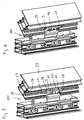
- eine Explosionsdarstellung des Flügelbandteils dieser Bandanordnung in einer perspektivischen Ansicht;
- Fig.2
- eine Seitenansicht dieser Bandanordnung im mit Montage- und Klemmstück zusammengefügten Zustand (Ansicht A in
Fig. 1 ) - Fig.3
- eine perspektivische Ansicht einer an abschnittsweise dargestellten Flügel- und Rahmenprofilen montierten Bandanordnung in einer ersten Justierstellung sowie
- Fig. 4
- eine
Fig. 3 entsprechende Ansicht in einer zweiten Justierstellung. - Die in der Zeichnung als Ganzes mit 100 bezeichnete Bandanordnung umfasst ein nur als Flügelbandteil verwendetes Bandteil 1, welches ein Befestigungsteil 2 und ein Scharnierteil 3 aufweist. Das Befestigungsteil 2 und das Scharnierteil 3 sind über einen abgewinkelten Verbindungsbereich 4 einstückig miteinander verbunden, wobei die Dimensionen des Verbindungsbereichs 4 an einen Dichtungsvorsprung angepasst sind, wie dies in
Fig. 3 und 4 erkennbar ist. - Das Befestigungsteil 2 weist eine im wesentlichen ebene Unterseite 7 auf, die einer Befestigungsfläche 8, die an einem Montagestück 20 vorgesehen ist, zugewandt ist. In das Befestigungsteil 2 sind des weiteren zwei Führungsausnehmungen 9 eingearbeitet, die als Durchgangsbohrungen ausgebildet sind. Der Durchmesser jeder Führungsausnehmung 9 ist an den Außendurchmesser eines Führungsbereichs 10 eines Führungsgliedes 11 derart angepasst, dass der Führungsbereich 10 mit der zugehörigen Führungsausnehmung 9 eine im wesentlichen spielfreie Gleitpassung bildet.
- Von einem stirnseitigen Ende 12 des Führungsbereichs 10 erstreckt sich ein Gewindefortsatz 13, der ein als Maschinengewinde ausgebildetes Außengewinde aufweist. An dem gegenüberliegenden stirnseitigen Ende ist an dem Führungsglied 11 ein Radialvorsprung 14 vorgesehen. Er bildet einen Anschlag für das Befestigungsteil 2.
- Ferner umfasst die erfindungsgemäße Bandanordnung ein Verstellglied 15, welches wiederum einen Gewindefortsatz 16 mit einem Maschinen-Außengewinde und einen Radialvorsprung 17 umfasst. Das Verstellglied 15 ist in Verstellrichtung P formschlüssig an dem Befestigungsteil 2 gelagert, da letzteres eine im Querschnitt C-förmige Nut 18 aufweist, deren Randlippen 19 Hinterschneidungen für den Radialvorsprung 17 bilden.
- Ferner umfasst die Bandanordnung ein Klemmstück 21 (
Fig. 2 ), welches plattenförmig ausgebildet ist und Dimensionen aufweist, dass es in eine sich in Längsrichtung eines Profils 22, hier des Flügelprofils erstreckende, im Querschnitt wiederum C-förmige Nut 23 derart einbringbar ist, dass es in von Randlippen 24 der Nut 23 gebildete, hinterschnittene Flächen eingreift. - Das Klemmstück 21 weist Gewindebohrungen 25 und 26 auf. In die Gewindebohrungen 25 greifen die Gewindefortsätze 13 der Führungsglieder 11, in die Gewindebohrung 26 der Gewindefortsatz 16 des Verstellgliedes 15 ein. Die Gewindefortsätze 13 und 16 durchsetzen das Montagestück 20 durch Bohrungen 27. Wie insbesondere in Verbindung mit den
Fig. 3 und 4 sinnfällig wird, führt ein Anziehen der Führungsglieder 11 dazu, dass das Klemmstück 21 gegen das Montagestück 20 gezogen wird und die Randlippen 24 der Nut 23 zwischen dem Klemmstück 21 und dem Montagestück 20 eingeklemmt werden, wodurch das Bandteil 1 an dem Profil 22 festgelegt wird. - Wie in
Fig. 3 und 4 dargestellt ist, können das Klemmstück 21 und das Montagestück 20 in Längsrichtung der Nut 23 länger als inFig. 2 dargestellt ausgebildet sein, so dass weitere, zusätzliche Klemmwirkungen hervorrufende Klemmschrauben 28 Verwendung finden können. - Eine Justierung des Flügels in dem Rahmen kann bei der erfindungsgemäßen Bandanordnung dadurch erfolgen, dass das Verstellglied 15 mittels eines geeigneten Werkzeuges gedreht wird. Durch den Eingriff des Gewindefortsatzes 16 in der Gewindebohrung 26 und der Lagerung des Radialvorsprungs 17 in der Nut 18 wird das Befestigungsteil 2 und damit das gesamte Bandteil 1 in Verstellrichtung P verlagert. Die eine Extremstellung ist durch Anlage der Radialvorsprünge 14 an dem Befestigungsteil 2 (s.
Fig. 3 ), die andere Extremstellung durch Anlage des Befestigungsteils 2 an dem Montagestück 20 (s.Fig. 4 ) definiert. -
- 100
- Bandanordnung
- 1
- Bandteil
- 2
- Befestigungsteil
- 3
- Scharnierteil
- 4
- Verbindungsbereich
- 5
- Dichtungsvorsprung
- 6
- Flügelprofil
- 7
- Unterseite
- 8
- Befestigungsfläche
- 9
- Führungsausnehmungen
- 10
- Führungsbereich
- 11
- Führungsglied
- 12
- stirnseitiges Ende
- 13
- Gewindefortsatz
- 14
- Radialvorsprung
- 15
- Verstellglied
- 16
- Gewindefortsatz
- 17
- Radialvorsprung
- 18
- Nut
- 19
- Randlippen
- 20
- Montagestück
- 21
- Klemmstück
- 22
- Profil
- 23
- Nut
- 24
- Randlippen
- 25
- Gewindebohrungen
- 26
- Gewindebohrung
- 27
- Bohrung
- 28
- Klemmschraube
- A
- Ansicht
- P
- Verstellrichtung
Claims (10)
- Bandanordnung für Türen, Fenster oder dergleichen, mit
einem Bandteil (1), einem Montagestück (20), einem Klemmstück (21), mindestens einem Führungsglied (11) und einem Verstellglied (15),
wobei das Bandteil (1) einen Scharnierteil (3) und einen Befestigungsteil (2) umfasst,
und das Montagestück (20) an einem Rahmen oder an einem Flügel befestigbar ist und eine Befestigungsfläche (8) aufweist, an der der Befestigungsteil (2) montierbar ist,
und das Führungsglied (11) mit einem stirnseitigen Ende (12) an der Befestigungsfläche (8) anbringbar ist und mit einem Führungsbereich (10) in einer Führungsausnehmung (9) in dem Befestigungsteil (2) führend eingreift, so dass das Befestigungsteil (2) senkrecht zur Befestigungsfläche (8) verlagerbar ist,
und das Verstellglied (15) einen Gewindefortsatz (16) und einen Radialvorsprung (17) aufweist, wobei
der Gewindefortsatz (16) mit einem komplementären, zur Befestigungsfläche (8) ortsfesten Gewinde (26) und der Radialvorsprung (17) mit einer Aufnahme an dem Befestigungsteil (2),
oder der Gewindefortsatz (16) mit einem komplementären Gewinde an dem Befestigungsteil (2) und der Radialvorsprung (17) mit einer zur Befestigungsfläche (8) ortsfesten Aufnahme in Eingriff bringbar ist,
dadurch gekennzeichnet,
dass das Montagestück (20) und das Klemmstück (21) Teil einer in eine an dem Rahmen oder an dem Flügel vorgesehenen Nut (23) eingreifenden Klemmeinrichtung ist, und zumindest das Führungsglied (11) mit einem von dem stirnseitigen Ende (12) sich erstreckenden Gewindefortsatz (13) mit einem komplementären Gewinde (25) des Klemmstücks (21) derart in Eingriff bringbar ist, dass eine Klemmwirkung durch das mindestens eine Führungsglied (11) bewirkt wird. - Bandanordnung nach Anspruch 1, dadurch gekennzeichnet, dass das Montagestück (20) eine Klemmplatte ist, die mit dem in hinterschnittene Flächen der Nut (23) eingreifenden Klemmstück (21) zusammenwirkt.
- Bandanordnung nach Anspruch 1 oder 2, dadurch gekennzeichnet, dass das Führungsglied (11) um seine Längsachse rotationssymmetrisch ausgebildet ist und den Gewindefortsatz (13) und den Führungsbereich (10) umfasst.
- Bandanordnung nach Anspruch 3, dadurch gekennzeichnet, dass der Gewindefortsatz (13) einen geringeren Durchmesser als der Führungsbereich (10) aufweist.
- Bandanordnung nach einem der Ansprüche 1 bis 4, dadurch gekennzeichnet, dass der Gewindefortsatz (13, 16) mit dem Klemmstück (21) zusammenwirkt.
- Bandanordnung nach Anspruch 4 oder 5, dadurch gekennzeichnet, dass an dem dem Gewindefortsatz (13) gegenüberliegenden Ende des Führungsbereichs (10) ein Radialvorsprung (14) vorgesehen ist.
- Bandanordnung nach einem der Ansprüche 1 bis 6, dadurch gekennzeichnet, dass an dem Befestigungsteil (2) eine Hinterschneidung vorgesehen ist, in die der Radialvorsprung (17) des Verstellgliedes (15) eingreift.
- Bandanordnung nach Anspruch 7, dadurch gekennzeichnet, dass die Hinterschneidung von den Randlippen (19) einer im Querschnitt C-förmigen Nut (18) gebildet ist.
- Bandanordnung nach einem der Ansprüche 1 bis 8, dadurch gekennzeichnet, dass das Gewinde des Gewindefortsatzes (13) des Führungsgliedes (11) selbstschneidend ist.
- Bandanordnung nach einem der Ansprüche 1 bis 8, dadurch gekennzeichnet, dass das Gewinde des Gewindefortsatzes (13) des Führungsgliedes (11) ein Maschinengewinde ist.
Priority Applications (1)
| Application Number | Priority Date | Filing Date | Title |
|---|---|---|---|
| PL07801946T PL2084356T3 (pl) | 2006-10-30 | 2007-08-29 | Układ zawiasy do drzwi, okien lub tym podobnych |
Applications Claiming Priority (2)
| Application Number | Priority Date | Filing Date | Title |
|---|---|---|---|
| DE202006016738U DE202006016738U1 (de) | 2006-10-30 | 2006-10-30 | Bandanordnung für Türen, Fenster u.dgl. |
| PCT/EP2007/007524 WO2008052611A1 (de) | 2006-10-30 | 2007-08-29 | Bandanordnung für türen, fenster oder dergleichen |
Publications (2)
| Publication Number | Publication Date |
|---|---|
| EP2084356A1 EP2084356A1 (de) | 2009-08-05 |
| EP2084356B1 true EP2084356B1 (de) | 2019-05-01 |
Family
ID=38672580
Family Applications (1)
| Application Number | Title | Priority Date | Filing Date |
|---|---|---|---|
| EP07801946.0A Active EP2084356B1 (de) | 2006-10-30 | 2007-08-29 | Bandanordnung für türen, fenster oder dergleichen |
Country Status (6)
| Country | Link |
|---|---|
| EP (1) | EP2084356B1 (de) |
| DE (1) | DE202006016738U1 (de) |
| PL (1) | PL2084356T3 (de) |
| RU (1) | RU2441971C2 (de) |
| UA (1) | UA94630C2 (de) |
| WO (1) | WO2008052611A1 (de) |
Families Citing this family (4)
| Publication number | Priority date | Publication date | Assignee | Title |
|---|---|---|---|---|
| WO2009010382A1 (de) | 2007-07-13 | 2009-01-22 | Hahn Gmbh & Co. Kg | Bandanordnung für türen, fenster oder dergleichen |
| DE102009045195A1 (de) | 2009-09-30 | 2011-03-31 | Schüring GmbH & Co. Fenstertechnologie KG | Bandteil für ein Gelenkband |
| CN103899173A (zh) * | 2014-04-15 | 2014-07-02 | 李健 | 一种合页组件 |
| BE1022089B1 (nl) * | 2014-08-13 | 2016-02-15 | Van Parys Remi Emiel | Hulpstuk voor regelen van de afstand tussen een scharnier en een profiel van een raam of deur en scharnier uitgerust met zulk hulpstuk |
Family Cites Families (4)
| Publication number | Priority date | Publication date | Assignee | Title |
|---|---|---|---|---|
| DE29806383U1 (de) * | 1998-04-07 | 1998-08-06 | Heine & Sohn Anuba Beschlaege | Band zur Lagerung eines Flügels einer Tür oder eines Fensters |
| DE10152366C5 (de) * | 2001-10-24 | 2004-12-02 | Simonswerk, Gmbh | Aufnahmevorrichtung zur in Türdicken- oder Türquerrichtung verstellbaren Halterung eines Bandlappens einer Türflügelschwenkhalterung an einem Hohlprofil, z.B. einem Aluminiumprofil |
| FR2876726B1 (fr) * | 2004-10-20 | 2011-04-01 | Laurent Lenzi | Nouveau type de gond reglable et pilier de soutenement pour le recevoir |
| ITBO20050157A1 (it) * | 2005-03-15 | 2006-09-16 | Gsg Int Spa | Dispositivo di posizionamento per infissi |
-
2006
- 2006-10-30 DE DE202006016738U patent/DE202006016738U1/de not_active Expired - Lifetime
-
2007
- 2007-08-29 PL PL07801946T patent/PL2084356T3/pl unknown
- 2007-08-29 UA UAA200905473A patent/UA94630C2/ru unknown
- 2007-08-29 EP EP07801946.0A patent/EP2084356B1/de active Active
- 2007-08-29 RU RU2009120462/12A patent/RU2441971C2/ru not_active IP Right Cessation
- 2007-08-29 WO PCT/EP2007/007524 patent/WO2008052611A1/de active Application Filing
Also Published As
| Publication number | Publication date |
|---|---|
| PL2084356T3 (pl) | 2019-09-30 |
| RU2441971C2 (ru) | 2012-02-10 |
| EP2084356A1 (de) | 2009-08-05 |
| DE202006016738U1 (de) | 2008-03-13 |
| UA94630C2 (ru) | 2011-05-25 |
| WO2008052611A1 (de) | 2008-05-08 |
| RU2009120462A (ru) | 2010-12-10 |
Similar Documents
| Publication | Publication Date | Title |
|---|---|---|
| EP0285229B2 (de) | Einstellbares Gelenkband, insbesondere für Türen | |
| EP2913465B1 (de) | Bandanordnung für türen, fenster oder dergleichen | |
| EP1972743B1 (de) | Schliessteil | |
| EP2084356B1 (de) | Bandanordnung für türen, fenster oder dergleichen | |
| EP2118416A1 (de) | Vorrichtung mit einem montageeinsatz zur befestigung von beschlagteilen an hohlprofilen sowie verfahren zur anbringung des montageeinsatzes an dem hohlprofil | |
| EP2024592A1 (de) | Band mit justierung | |
| DE102008006800B4 (de) | Führungsvorrichtung für einen Schiebeflügel | |
| EP1256681B1 (de) | Beschlag für ein Verschlusselement für eine Maueröffnung | |
| EP1619336A2 (de) | Justierbares Band für Fenster, Türen und dergleichen | |
| EP1563152B1 (de) | Gelenkband | |
| DE202004013848U1 (de) | Band für Fenster, Türen u.dgl. | |
| DE202008016071U1 (de) | Band zur scharniergelenkigen Verbindung eines Flügels an einem Rahmen | |
| WO2021073830A1 (de) | Band zur befestigung eines flügels an einem rahmen sowie anordnung mit einem hohlprofil und mit diesem band | |
| WO2010003435A1 (de) | Bandsystem | |
| DE202005014093U1 (de) | Band für Türen, Fenster o.dgl. | |
| EP2514892B1 (de) | System zur Befestigung eines Beschlagteils | |
| EP2540942B1 (de) | Verstellbare Beschlagsanordnung | |
| EP1126110B1 (de) | Schliessvorrichtung für Türen und Fenster | |
| EP2818617B1 (de) | Bandaufnahmeelement für Türbänder | |
| EP0945574B1 (de) | Band für Türen, Fenster oder dergleichen | |
| WO2022128247A1 (de) | Betätigungshandhabe für rosettenlose fenster und türen | |
| DE202012104306U1 (de) | Band für Türen, Fenster oder dergleichen | |
| DE102005032329A1 (de) | Gleitschiene | |
| DE202005021143U1 (de) | Gleitschiene |
Legal Events
| Date | Code | Title | Description |
|---|---|---|---|
| PUAI | Public reference made under article 153(3) epc to a published international application that has entered the european phase |
Free format text: ORIGINAL CODE: 0009012 |
|
| 17P | Request for examination filed |
Effective date: 20090505 |
|
| AK | Designated contracting states |
Kind code of ref document: A1 Designated state(s): AT BE BG CH CY CZ DE DK EE ES FI FR GB GR HU IE IS IT LI LT LU LV MC MT NL PL PT RO SE SI SK TR |
|
| RIN1 | Information on inventor provided before grant (corrected) |
Inventor name: LENZE, MARKUS |
|
| DAX | Request for extension of the european patent (deleted) | ||
| 17Q | First examination report despatched |
Effective date: 20140527 |
|
| STAA | Information on the status of an ep patent application or granted ep patent |
Free format text: STATUS: EXAMINATION IS IN PROGRESS |
|
| GRAP | Despatch of communication of intention to grant a patent |
Free format text: ORIGINAL CODE: EPIDOSNIGR1 |
|
| STAA | Information on the status of an ep patent application or granted ep patent |
Free format text: STATUS: GRANT OF PATENT IS INTENDED |
|
| INTG | Intention to grant announced |
Effective date: 20181218 |
|
| GRAS | Grant fee paid |
Free format text: ORIGINAL CODE: EPIDOSNIGR3 |
|
| GRAA | (expected) grant |
Free format text: ORIGINAL CODE: 0009210 |
|
| STAA | Information on the status of an ep patent application or granted ep patent |
Free format text: STATUS: THE PATENT HAS BEEN GRANTED |
|
| AK | Designated contracting states |
Kind code of ref document: B1 Designated state(s): AT BE BG CH CY CZ DE DK EE ES FI FR GB GR HU IE IS IT LI LT LU LV MC MT NL PL PT RO SE SI SK TR |
|
| REG | Reference to a national code |
Ref country code: GB Ref legal event code: FG4D Free format text: NOT ENGLISH |
|
| REG | Reference to a national code |
Ref country code: CH Ref legal event code: EP Ref country code: AT Ref legal event code: REF Ref document number: 1127098 Country of ref document: AT Kind code of ref document: T Effective date: 20190515 |
|
| REG | Reference to a national code |
Ref country code: DE Ref legal event code: R096 Ref document number: 502007016659 Country of ref document: DE |
|
| REG | Reference to a national code |
Ref country code: IE Ref legal event code: FG4D Free format text: LANGUAGE OF EP DOCUMENT: GERMAN |
|
| REG | Reference to a national code |
Ref country code: NL Ref legal event code: MP Effective date: 20190501 |
|
| REG | Reference to a national code |
Ref country code: LT Ref legal event code: MG4D |
|
| PG25 | Lapsed in a contracting state [announced via postgrant information from national office to epo] |
Ref country code: ES Free format text: LAPSE BECAUSE OF FAILURE TO SUBMIT A TRANSLATION OF THE DESCRIPTION OR TO PAY THE FEE WITHIN THE PRESCRIBED TIME-LIMIT Effective date: 20190501 Ref country code: NL Free format text: LAPSE BECAUSE OF FAILURE TO SUBMIT A TRANSLATION OF THE DESCRIPTION OR TO PAY THE FEE WITHIN THE PRESCRIBED TIME-LIMIT Effective date: 20190501 Ref country code: PT Free format text: LAPSE BECAUSE OF FAILURE TO SUBMIT A TRANSLATION OF THE DESCRIPTION OR TO PAY THE FEE WITHIN THE PRESCRIBED TIME-LIMIT Effective date: 20190901 Ref country code: SE Free format text: LAPSE BECAUSE OF FAILURE TO SUBMIT A TRANSLATION OF THE DESCRIPTION OR TO PAY THE FEE WITHIN THE PRESCRIBED TIME-LIMIT Effective date: 20190501 Ref country code: LT Free format text: LAPSE BECAUSE OF FAILURE TO SUBMIT A TRANSLATION OF THE DESCRIPTION OR TO PAY THE FEE WITHIN THE PRESCRIBED TIME-LIMIT Effective date: 20190501 Ref country code: FI Free format text: LAPSE BECAUSE OF FAILURE TO SUBMIT A TRANSLATION OF THE DESCRIPTION OR TO PAY THE FEE WITHIN THE PRESCRIBED TIME-LIMIT Effective date: 20190501 |
|
| PG25 | Lapsed in a contracting state [announced via postgrant information from national office to epo] |
Ref country code: GR Free format text: LAPSE BECAUSE OF FAILURE TO SUBMIT A TRANSLATION OF THE DESCRIPTION OR TO PAY THE FEE WITHIN THE PRESCRIBED TIME-LIMIT Effective date: 20190802 Ref country code: BG Free format text: LAPSE BECAUSE OF FAILURE TO SUBMIT A TRANSLATION OF THE DESCRIPTION OR TO PAY THE FEE WITHIN THE PRESCRIBED TIME-LIMIT Effective date: 20190801 Ref country code: LV Free format text: LAPSE BECAUSE OF FAILURE TO SUBMIT A TRANSLATION OF THE DESCRIPTION OR TO PAY THE FEE WITHIN THE PRESCRIBED TIME-LIMIT Effective date: 20190501 |
|
| PG25 | Lapsed in a contracting state [announced via postgrant information from national office to epo] |
Ref country code: IS Free format text: LAPSE BECAUSE OF FAILURE TO SUBMIT A TRANSLATION OF THE DESCRIPTION OR TO PAY THE FEE WITHIN THE PRESCRIBED TIME-LIMIT Effective date: 20190901 |
|
| PG25 | Lapsed in a contracting state [announced via postgrant information from national office to epo] |
Ref country code: DK Free format text: LAPSE BECAUSE OF FAILURE TO SUBMIT A TRANSLATION OF THE DESCRIPTION OR TO PAY THE FEE WITHIN THE PRESCRIBED TIME-LIMIT Effective date: 20190501 Ref country code: SK Free format text: LAPSE BECAUSE OF FAILURE TO SUBMIT A TRANSLATION OF THE DESCRIPTION OR TO PAY THE FEE WITHIN THE PRESCRIBED TIME-LIMIT Effective date: 20190501 Ref country code: RO Free format text: LAPSE BECAUSE OF FAILURE TO SUBMIT A TRANSLATION OF THE DESCRIPTION OR TO PAY THE FEE WITHIN THE PRESCRIBED TIME-LIMIT Effective date: 20190501 Ref country code: CZ Free format text: LAPSE BECAUSE OF FAILURE TO SUBMIT A TRANSLATION OF THE DESCRIPTION OR TO PAY THE FEE WITHIN THE PRESCRIBED TIME-LIMIT Effective date: 20190501 Ref country code: EE Free format text: LAPSE BECAUSE OF FAILURE TO SUBMIT A TRANSLATION OF THE DESCRIPTION OR TO PAY THE FEE WITHIN THE PRESCRIBED TIME-LIMIT Effective date: 20190501 |
|
| REG | Reference to a national code |
Ref country code: DE Ref legal event code: R097 Ref document number: 502007016659 Country of ref document: DE |
|
| PLBE | No opposition filed within time limit |
Free format text: ORIGINAL CODE: 0009261 |
|
| STAA | Information on the status of an ep patent application or granted ep patent |
Free format text: STATUS: NO OPPOSITION FILED WITHIN TIME LIMIT |
|
| PG25 | Lapsed in a contracting state [announced via postgrant information from national office to epo] |
Ref country code: TR Free format text: LAPSE BECAUSE OF FAILURE TO SUBMIT A TRANSLATION OF THE DESCRIPTION OR TO PAY THE FEE WITHIN THE PRESCRIBED TIME-LIMIT Effective date: 20190501 |
|
| 26N | No opposition filed |
Effective date: 20200204 |
|
| GBPC | Gb: european patent ceased through non-payment of renewal fee |
Effective date: 20190829 |
|
| PG25 | Lapsed in a contracting state [announced via postgrant information from national office to epo] |
Ref country code: MC Free format text: LAPSE BECAUSE OF FAILURE TO SUBMIT A TRANSLATION OF THE DESCRIPTION OR TO PAY THE FEE WITHIN THE PRESCRIBED TIME-LIMIT Effective date: 20190501 Ref country code: CH Free format text: LAPSE BECAUSE OF NON-PAYMENT OF DUE FEES Effective date: 20190831 Ref country code: LU Free format text: LAPSE BECAUSE OF NON-PAYMENT OF DUE FEES Effective date: 20190829 Ref country code: LI Free format text: LAPSE BECAUSE OF NON-PAYMENT OF DUE FEES Effective date: 20190831 Ref country code: SI Free format text: LAPSE BECAUSE OF FAILURE TO SUBMIT A TRANSLATION OF THE DESCRIPTION OR TO PAY THE FEE WITHIN THE PRESCRIBED TIME-LIMIT Effective date: 20190501 |
|
| REG | Reference to a national code |
Ref country code: BE Ref legal event code: MM Effective date: 20190831 |
|
| PG25 | Lapsed in a contracting state [announced via postgrant information from national office to epo] |
Ref country code: IE Free format text: LAPSE BECAUSE OF NON-PAYMENT OF DUE FEES Effective date: 20190829 |
|
| PG25 | Lapsed in a contracting state [announced via postgrant information from national office to epo] |
Ref country code: GB Free format text: LAPSE BECAUSE OF NON-PAYMENT OF DUE FEES Effective date: 20190829 Ref country code: BE Free format text: LAPSE BECAUSE OF NON-PAYMENT OF DUE FEES Effective date: 20190831 |
|
| REG | Reference to a national code |
Ref country code: AT Ref legal event code: MM01 Ref document number: 1127098 Country of ref document: AT Kind code of ref document: T Effective date: 20190829 |
|
| PG25 | Lapsed in a contracting state [announced via postgrant information from national office to epo] |
Ref country code: AT Free format text: LAPSE BECAUSE OF NON-PAYMENT OF DUE FEES Effective date: 20190829 |
|
| PG25 | Lapsed in a contracting state [announced via postgrant information from national office to epo] |
Ref country code: CY Free format text: LAPSE BECAUSE OF FAILURE TO SUBMIT A TRANSLATION OF THE DESCRIPTION OR TO PAY THE FEE WITHIN THE PRESCRIBED TIME-LIMIT Effective date: 20190501 |
|
| PG25 | Lapsed in a contracting state [announced via postgrant information from national office to epo] |
Ref country code: HU Free format text: LAPSE BECAUSE OF FAILURE TO SUBMIT A TRANSLATION OF THE DESCRIPTION OR TO PAY THE FEE WITHIN THE PRESCRIBED TIME-LIMIT; INVALID AB INITIO Effective date: 20070829 Ref country code: MT Free format text: LAPSE BECAUSE OF FAILURE TO SUBMIT A TRANSLATION OF THE DESCRIPTION OR TO PAY THE FEE WITHIN THE PRESCRIBED TIME-LIMIT Effective date: 20190501 |
|
| REG | Reference to a national code |
Ref country code: DE Ref legal event code: R082 Ref document number: 502007016659 Country of ref document: DE Representative=s name: PATENTANWAELTE KLUIN DEBELIUS WEBER PARTG MBB, DE |
|
| P01 | Opt-out of the competence of the unified patent court (upc) registered |
Effective date: 20230523 |
|
| PGFP | Annual fee paid to national office [announced via postgrant information from national office to epo] |
Ref country code: PL Payment date: 20230630 Year of fee payment: 17 |
|
| PGFP | Annual fee paid to national office [announced via postgrant information from national office to epo] |
Ref country code: IT Payment date: 20230711 Year of fee payment: 17 |
|
| PGFP | Annual fee paid to national office [announced via postgrant information from national office to epo] |
Ref country code: FR Payment date: 20230703 Year of fee payment: 17 Ref country code: DE Payment date: 20230831 Year of fee payment: 17 |