EP2084356B1 - Ensemble de ferrure pour portes, fenêtres ou analogues - Google Patents
Ensemble de ferrure pour portes, fenêtres ou analogues Download PDFInfo
- Publication number
- EP2084356B1 EP2084356B1 EP07801946.0A EP07801946A EP2084356B1 EP 2084356 B1 EP2084356 B1 EP 2084356B1 EP 07801946 A EP07801946 A EP 07801946A EP 2084356 B1 EP2084356 B1 EP 2084356B1
- Authority
- EP
- European Patent Office
- Prior art keywords
- guide
- threaded extension
- hinge arrangement
- arrangement according
- fastening
- Prior art date
- Legal status (The legal status is an assumption and is not a legal conclusion. Google has not performed a legal analysis and makes no representation as to the accuracy of the status listed.)
- Active
Links
- 230000000295 complement effect Effects 0.000 claims description 8
- 230000000694 effects Effects 0.000 claims description 3
- 240000006829 Ficus sundaica Species 0.000 description 2
- 230000003750 conditioning effect Effects 0.000 description 2
- 238000004519 manufacturing process Methods 0.000 description 2
- 238000007789 sealing Methods 0.000 description 2
- 238000010276 construction Methods 0.000 description 1
- 238000005553 drilling Methods 0.000 description 1
- 238000003780 insertion Methods 0.000 description 1
- 230000037431 insertion Effects 0.000 description 1
- 238000002360 preparation method Methods 0.000 description 1
- 238000010079 rubber tapping Methods 0.000 description 1
Images

Classifications
-
- E—FIXED CONSTRUCTIONS
- E05—LOCKS; KEYS; WINDOW OR DOOR FITTINGS; SAFES
- E05D—HINGES OR SUSPENSION DEVICES FOR DOORS, WINDOWS OR WINGS
- E05D5/00—Construction of single parts, e.g. the parts for attachment
- E05D5/02—Parts for attachment, e.g. flaps
- E05D5/0215—Parts for attachment, e.g. flaps for attachment to profile members or the like
- E05D5/0223—Parts for attachment, e.g. flaps for attachment to profile members or the like with parts, e.g. screws, extending through the profile wall or engaging profile grooves
- E05D5/0238—Parts for attachment, e.g. flaps for attachment to profile members or the like with parts, e.g. screws, extending through the profile wall or engaging profile grooves with parts engaging profile grooves
-
- E—FIXED CONSTRUCTIONS
- E05—LOCKS; KEYS; WINDOW OR DOOR FITTINGS; SAFES
- E05D—HINGES OR SUSPENSION DEVICES FOR DOORS, WINDOWS OR WINGS
- E05D7/00—Hinges or pivots of special construction
- E05D7/04—Hinges adjustable relative to the wing or the frame
- E05D7/043—Hinges adjustable relative to the wing or the frame by means of dowel attachments
-
- E—FIXED CONSTRUCTIONS
- E05—LOCKS; KEYS; WINDOW OR DOOR FITTINGS; SAFES
- E05Y—INDEXING SCHEME ASSOCIATED WITH SUBCLASSES E05D AND E05F, RELATING TO CONSTRUCTION ELEMENTS, ELECTRIC CONTROL, POWER SUPPLY, POWER SIGNAL OR TRANSMISSION, USER INTERFACES, MOUNTING OR COUPLING, DETAILS, ACCESSORIES, AUXILIARY OPERATIONS NOT OTHERWISE PROVIDED FOR, APPLICATION THEREOF
- E05Y2600/00—Mounting or coupling arrangements for elements provided for in this subclass
- E05Y2600/60—Mounting or coupling members; Accessories therefor
- E05Y2600/63—Retainers
-
- E—FIXED CONSTRUCTIONS
- E05—LOCKS; KEYS; WINDOW OR DOOR FITTINGS; SAFES
- E05Y—INDEXING SCHEME ASSOCIATED WITH SUBCLASSES E05D AND E05F, RELATING TO CONSTRUCTION ELEMENTS, ELECTRIC CONTROL, POWER SUPPLY, POWER SIGNAL OR TRANSMISSION, USER INTERFACES, MOUNTING OR COUPLING, DETAILS, ACCESSORIES, AUXILIARY OPERATIONS NOT OTHERWISE PROVIDED FOR, APPLICATION THEREOF
- E05Y2900/00—Application of doors, windows, wings or fittings thereof
- E05Y2900/10—Application of doors, windows, wings or fittings thereof for buildings or parts thereof
- E05Y2900/13—Type of wing
- E05Y2900/132—Doors
-
- E—FIXED CONSTRUCTIONS
- E05—LOCKS; KEYS; WINDOW OR DOOR FITTINGS; SAFES
- E05Y—INDEXING SCHEME ASSOCIATED WITH SUBCLASSES E05D AND E05F, RELATING TO CONSTRUCTION ELEMENTS, ELECTRIC CONTROL, POWER SUPPLY, POWER SIGNAL OR TRANSMISSION, USER INTERFACES, MOUNTING OR COUPLING, DETAILS, ACCESSORIES, AUXILIARY OPERATIONS NOT OTHERWISE PROVIDED FOR, APPLICATION THEREOF
- E05Y2900/00—Application of doors, windows, wings or fittings thereof
- E05Y2900/10—Application of doors, windows, wings or fittings thereof for buildings or parts thereof
- E05Y2900/13—Type of wing
- E05Y2900/148—Windows
Definitions
- the invention relates to a band assembly for doors, windows or the like with a hinge part, which comprises a hinge part and a fastening part, wherein the attachment part is arranged to be displaceable relative to the fastening surface facing it to create the adjustment possibility of the wing in the frame.
- Such a band arrangement is for example from the DE 101 52 366 C5 known. It comprises a receiving piece which can be fixed in a hollow profile. In the receiving piece guide bores are provided, which continue in perforations in a mounting side forming the profile wall. On the fastening part of the hinge part support pins are provided, which are designed to be inserted into the guide holes and optionally spreadable, so that the determination of the hinge part can be done in the desired position by jamming the support pins in the guide holes.
- the adjustment of the wing in the frame for the purpose of adjustment is a threaded element which is fixed to the fastening part in the adjustment direction and has an external thread which can be screwed into a complementary, provided in the receiving piece internal thread.
- a band assembly with a mounted on a mounting surface guide member known.
- the mounting surface is formed by a mountable on a profile mounting member to which the guide member in one piece is formed. It has a rectangular cross-section.
- a hinge part surrounding it on the outside is displaceably arranged with the aid of an adjusting member in the longitudinal direction of the guide member.
- the invention is therefore an object of the invention to provide a band assembly, which allows adjustment of the band portion relative to the mounting surface of a frame or a wing for the purpose of adjustment and is inexpensive to produce.
- the fastening part can be mounted on a fastening surface which is formed by a surface of a mounting piece which can be fastened to a frame or to a wing.
- the band assembly according to the invention comprises at least one attachable to the mounting surface guide member which engages leading into a guide recess in the fastening part, which can be accomplished for example by at least substantially free of play recording in the guide recess, so that the fastening part is perpendicular to the mounting surface displaced.
- the band assembly further includes an adjustment member having a threaded shaft and a radial projection, wherein the threaded shaft with a complementary, fixed to the mounting surface thread and the radial projection with a receptacle on the fastening part, or the threaded shaft with a complementary thread on the fastening part and the radial projection can be brought into engagement with a stationary mounting to the mounting surface on the frame or wing.
- the band assembly according to the invention requires only the at least one guide and the at least one adjusting member for the adjustment.
- the mounting piece according to the invention is part of a clamping device engaging in a groove provided on the frame or on the wing. Because of this design, the band assembly according to the invention is particularly suitable to be mounted on hollow profiles with an externally accessible groove, as they are used in particular in modern door construction.
- the clamping device is designed such that the clamping action that positions the band assembly on the frame or the wing, is effected by the at least one guide member.
- a complementary to the threaded extension of the guide member threaded bore is provided in the clamping piece, in which the threaded extension is screwed.
- the mounting piece may then be a clamping plate which cooperates with an engaging in undercut surfaces of the groove clamping piece.
- the undercut surfaces of the groove may be formed by profile projections of an extending in the longitudinal direction of the frame or wing profile, outwardly open, in cross-section C-shaped groove.
- the guide member is rotationally symmetrical about its longitudinal axis, as this simplifies the production of the band assembly. It also has a threaded extension, with which the guide member is screwed into the frame or the wing, and a guide portion which cooperates with the guide recess of the fastening part of the hinge part on.
- the thread extension has a smaller diameter than the guide region.
- the clamping action required for determining the band arrangement on the frame or the wing can be effected in such an embodiment of the guide member, that the threaded extension cooperates with the clamping piece, in particular in that in the clamping piece a threaded bore complementary to the threaded extension is provided in the the threaded extension is screwed. Since the end face of the guide portion comes into abutment with the mounting surface, tightening the guide member causes the clamp to be attracted to the mounting pad forming the mounting surface, thereby achieving the clamping effect.
- a development is particularly preferred in which a radial projection is provided on the end of the guide region opposite the thread extension. This then serves as a stop for the fastening part of the band part and thus limits the adjustment.
- an undercut is provided on the fastening part of the band part, in which engages the radial projection of the adjusting member.
- the undercut is formed by edge lips of a cross-sectionally C-shaped groove which runs perpendicular to the adjustment direction.
- the adjusting member can then be mounted with the undercut in a simple manner by lateral insertion.
- the thread of the threaded extension of the guide member may be self-tapping.
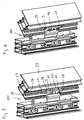
- the band arrangement indicated as 100 in the drawing as a whole comprises a band part 1 which is used only as a wing band part and which has a fastening part 2 and a hinge part 3.
- the fastening part 2 and the hinge part 3 are integrally connected to one another via an angled connecting region 4, wherein the dimensions of the connecting region 4 are adapted to a sealing projection, as shown in FIG 3 and 4 is recognizable.
- the fastening part 2 has a substantially flat underside 7, which faces a fastening surface 8, which is provided on a mounting piece 20.
- two guide recesses 9 are incorporated, which are formed as through holes.
- the diameter of each guide recess 9 is adapted to the outer diameter of a guide portion 10 of a guide member 11 such that the guide portion 10 forms a substantially backlash-free sliding fit with the associated guide recess 9.
- a threaded extension 13 which has a thread formed as a machine thread external thread.
- a radial projection 14 is provided on the guide member 11. It forms a stop for the fastening part 2.
- the band assembly comprises an adjusting member 15, which in turn comprises a threaded extension 16 with a machine external thread and a radial projection 17.
- the adjusting member 15 is mounted in the adjustment direction P form-fitting manner on the fastening part 2, since the latter has a cross-sectionally C-shaped groove 18, the edge lips 19 form undercuts for the radial projection 17.
- the band arrangement comprises a clamping piece 21 (FIG. Fig. 2 ), which is plate-shaped and has dimensions such that it can be introduced into a groove 23 extending in the longitudinal direction of a profile 22, in this case the wing profile, again in cross-section, in such a way that it is undercut in marginal lips 24 of the groove 23 Intervening surfaces.
- the clamping piece 21 has threaded bores 25 and 26. In the threaded holes 25 engage the threaded extensions 13 of the guide members 11, in the threaded bore 26 of the threaded extension 16 of the adjusting member 15 a. The threaded extensions 13 and 16 pass through the mounting piece 20 through holes 27. As in particular in connection with the 3 and 4 is apparent, a tightening of the guide members 11 causes the clamping piece 21 is pulled against the mounting piece 20 and the edge lips 24 of the groove 23 between the clamping piece 21 and the mounting piece 20 are clamped, whereby the band part 1 is fixed to the profile 22.
- clamping piece 21 and the mounting piece 20 in the longitudinal direction of the groove 23 longer than in Fig. 2 may be formed, so that more, additional clamping effects causing clamping screws 28 may be used.
- An adjustment of the wing in the frame can be carried out in the band assembly according to the invention characterized in that the adjusting member 15 is rotated by means of a suitable tool.
- the fastening part 2 and thus the entire band part 1 is displaced in the adjustment direction P.
- the one extreme position is by conditioning the radial projections 14 on the fastening part 2 (s. Fig. 3 ), the other extreme position by conditioning of the fastening part 2 on the mounting piece 20 (s. Fig. 4 ) are defined.
Landscapes
- Engineering & Computer Science (AREA)
- Mechanical Engineering (AREA)
- Hinges (AREA)
Claims (10)
- Ensemble formant penture destiné à des portes, des fenêtres ou similaires, comprenant
un élément de penture (1), une pièce de montage (20), une pièce de serrage (21), au moins un élément de guidage (11) et un élément de réglage (15),
L'élément de penture (1) comprenant une partie formant charnière (3) et une partie de fixation (2),
et la pièce de montage (20) pouvant être fixée à un encadrement ou à un battant et présentant une surface de fixation (8) sur laquelle la partie de fixation (2) peut être montée,
et l'élément de guidage (11) pouvant être monté, par une extrémité frontale (12), sur la surface de fixaton (8) et venant en engagement de guidage par une région de guidage (10) dans un évidement de guidage (9) ménagé dans la partie de fixation (2) de sorte que la partie de fixation (2) peut être déplacé perpendiculairement à la surface de montage (8),
et l'élément de réglage (15) comportant une extension filetée (16) et une saillie radiale (17), l'extension filetée (16) pouvant venir en engagement avec un filetage complémentaire (26), fixe par rapport à la surface de fixation (8), et la saillie radiale (17) pouvant venir en engagement avec un logement au niveau de la partie de fixation (2),
ou l'extension filetée (16) pouvant venir en engagement avec un filetage complémentaire au niveau de la partie de fixation (2) et la saillie radiale (17) pouvant venir en engagement avec un logement fixe par rapport à la surface de fixation (8),
caractérisé en ce que
la pièce de montage (20) et la pièce de serrage (21) font partie d'un dispositif de serrage s'engageant dans une gorge (23) prévue au niveau de l'encadrement ou au niveau du battant et au moins l'élément de guidage (11) pouvant venir en engagement, par une extension filetée s'étendant depuis l'extrémité frontal (12), avec un filetage complémentaire (25) de la pièce de serrage (21) de sorte qu'une action de serrage soit exercée par l'au moins un élément de guidage (11). - Ensemble formant penture selon la revendication 1, caractérisé en ce que la pièce de montage (20) est une plaque de serrage qui coopère avec la pièce de serrage (21) venant en engagement dans des surfaces en contre-dépouille de la gorge (23).
- Ensemble formant penture selon la revendication 1 ou 2, caractérisé en ce que l'élément de guidage (11) est à symétrique en rotation autour de son axe longitudinal et comporte l'extension filetée (13) et la région de guidage (10).
- Ensemble formant penture selon la revendication 3, caractérisé en ce que l'extension filetée (13) a un diamètre inférieur à celui de la région de guidage (10).
- Ensemble formant penture selon l'une des revendications 1 à 4, caractérisé en ce que l'extension filetée (13, 16) coopère avec la pièce de serrage (21).
- Ensemble formant penture selon la revendication 4 ou 5, caractérisé en ce qu'une saillie radiale (14) est prévue à l'extrémité, opposée à l'extension filetée (13, 16), de la région de guidage (10).
- Ensemble formant penture selon l'une des revendications 1 à 6, caractérisé en ce qu'il est prévu au niveau de la partie de fixation (2) une contre-dépouille dans laquelle s'engage la saillie radiale (17) de l'élément de réglage (15).
- Ensemble formant penture selon la revendication 7, caractérisé en ce que la contre-dépouille est formée des lèvres de bord (19) d'une gorge (18) en forme de C en coupe transversale.
- Ensemble formant penture selon l'une des revendications 1 à 8, caractérisé en ce que le filetage de l'extension filetée (13) de l'élément de guidage (11) est auto-taraudant.
- Ensemble formant penture selon l'une des revendications 1 à 8, caractérisé en ce que le filetage de l'extension filetée (13) de l'élément de guidage (11) est un filetage machine.
Priority Applications (1)
| Application Number | Priority Date | Filing Date | Title |
|---|---|---|---|
| PL07801946T PL2084356T3 (pl) | 2006-10-30 | 2007-08-29 | Układ zawiasy do drzwi, okien lub tym podobnych |
Applications Claiming Priority (2)
| Application Number | Priority Date | Filing Date | Title |
|---|---|---|---|
| DE202006016738U DE202006016738U1 (de) | 2006-10-30 | 2006-10-30 | Bandanordnung für Türen, Fenster u.dgl. |
| PCT/EP2007/007524 WO2008052611A1 (fr) | 2006-10-30 | 2007-08-29 | Ensemble de ferrure pour portes, fenêtres ou analogues |
Publications (2)
| Publication Number | Publication Date |
|---|---|
| EP2084356A1 EP2084356A1 (fr) | 2009-08-05 |
| EP2084356B1 true EP2084356B1 (fr) | 2019-05-01 |
Family
ID=38672580
Family Applications (1)
| Application Number | Title | Priority Date | Filing Date |
|---|---|---|---|
| EP07801946.0A Active EP2084356B1 (fr) | 2006-10-30 | 2007-08-29 | Ensemble de ferrure pour portes, fenêtres ou analogues |
Country Status (6)
| Country | Link |
|---|---|
| EP (1) | EP2084356B1 (fr) |
| DE (1) | DE202006016738U1 (fr) |
| PL (1) | PL2084356T3 (fr) |
| RU (1) | RU2441971C2 (fr) |
| UA (1) | UA94630C2 (fr) |
| WO (1) | WO2008052611A1 (fr) |
Families Citing this family (4)
| Publication number | Priority date | Publication date | Assignee | Title |
|---|---|---|---|---|
| RU2010105069A (ru) | 2007-07-13 | 2011-08-20 | Др.Хан Гмбх Унд Ко.Кг (De) | Петельное устройство для дверей, окон или т.п. |
| DE102009045195A1 (de) | 2009-09-30 | 2011-03-31 | Schüring GmbH & Co. Fenstertechnologie KG | Bandteil für ein Gelenkband |
| CN103899173A (zh) * | 2014-04-15 | 2014-07-02 | 李健 | 一种合页组件 |
| BE1022089B1 (nl) * | 2014-08-13 | 2016-02-15 | Van Parys Remi Emiel | Hulpstuk voor regelen van de afstand tussen een scharnier en een profiel van een raam of deur en scharnier uitgerust met zulk hulpstuk |
Family Cites Families (4)
| Publication number | Priority date | Publication date | Assignee | Title |
|---|---|---|---|---|
| DE29806383U1 (de) * | 1998-04-07 | 1998-08-06 | Anuba-Beschläge X. Heine & Sohn GmbH, 78147 Vöhrenbach | Band zur Lagerung eines Flügels einer Tür oder eines Fensters |
| DE10152366C5 (de) * | 2001-10-24 | 2004-12-02 | Simonswerk, Gmbh | Aufnahmevorrichtung zur in Türdicken- oder Türquerrichtung verstellbaren Halterung eines Bandlappens einer Türflügelschwenkhalterung an einem Hohlprofil, z.B. einem Aluminiumprofil |
| FR2876726B1 (fr) * | 2004-10-20 | 2011-04-01 | Laurent Lenzi | Nouveau type de gond reglable et pilier de soutenement pour le recevoir |
| ITBO20050157A1 (it) * | 2005-03-15 | 2006-09-16 | Gsg Int Spa | Dispositivo di posizionamento per infissi |
-
2006
- 2006-10-30 DE DE202006016738U patent/DE202006016738U1/de not_active Expired - Lifetime
-
2007
- 2007-08-29 PL PL07801946T patent/PL2084356T3/pl unknown
- 2007-08-29 RU RU2009120462/12A patent/RU2441971C2/ru not_active IP Right Cessation
- 2007-08-29 UA UAA200905473A patent/UA94630C2/ru unknown
- 2007-08-29 WO PCT/EP2007/007524 patent/WO2008052611A1/fr active Application Filing
- 2007-08-29 EP EP07801946.0A patent/EP2084356B1/fr active Active
Also Published As
| Publication number | Publication date |
|---|---|
| EP2084356A1 (fr) | 2009-08-05 |
| PL2084356T3 (pl) | 2019-09-30 |
| RU2441971C2 (ru) | 2012-02-10 |
| WO2008052611A1 (fr) | 2008-05-08 |
| DE202006016738U1 (de) | 2008-03-13 |
| RU2009120462A (ru) | 2010-12-10 |
| UA94630C2 (ru) | 2011-05-25 |
Similar Documents
| Publication | Publication Date | Title |
|---|---|---|
| EP0285229B2 (fr) | Charnière réglable, en particulier pour portes | |
| EP2913465B1 (fr) | Dispositif de charniere pour portes, fenetres ou similaires | |
| EP2084356B1 (fr) | Ensemble de ferrure pour portes, fenêtres ou analogues | |
| EP2118416A1 (fr) | Dispositif comprenant un insert de montage pour la fixation de ferrures sur des profilés creux ainsi que procédé pour la pose de l'insert de montage sur le profilé creux | |
| EP4045746A1 (fr) | Charnière pour la fixation d'une aile à un cadre, et agencement comprenant un profilé creux et ladite charnière | |
| WO2007140876A1 (fr) | Bande avec réglage | |
| DE102008006800B4 (de) | Führungsvorrichtung für einen Schiebeflügel | |
| EP1256681B1 (fr) | Ferrure pour un élément de fermeture d'une ouverture dans un mur | |
| EP1619336A2 (fr) | Charnière réglable pour fenêtres, portes ou similaires | |
| EP1563152B1 (fr) | Charniere | |
| DE202004013848U1 (de) | Band für Fenster, Türen u.dgl. | |
| DE202008016071U1 (de) | Band zur scharniergelenkigen Verbindung eines Flügels an einem Rahmen | |
| DE202005014093U1 (de) | Band für Türen, Fenster o.dgl. | |
| EP2514892B1 (fr) | Système de fixation d'une partie de ferrure | |
| EP4198251B1 (fr) | Système de fixation pour une installation d'ombrage | |
| EP2540942B1 (fr) | Agencement de ferrure réglable | |
| EP1126110B1 (fr) | Dispositif de fermeture pour portes et fenêtres | |
| EP2818617B1 (fr) | Réceptacle pour supporter une paumelle d'une charnière de porte | |
| EP0945574B1 (fr) | Charnière pour portes, fenêtres ou similaires | |
| DE102020134060A1 (de) | Betätigungshandhabe für rosettenlose fenster und türen | |
| EP4375463A1 (fr) | Élément de ferrure | |
| DE202012104306U1 (de) | Band für Türen, Fenster oder dergleichen | |
| DE102005032329A1 (de) | Gleitschiene | |
| DE202005021143U1 (de) | Gleitschiene |
Legal Events
| Date | Code | Title | Description |
|---|---|---|---|
| PUAI | Public reference made under article 153(3) epc to a published international application that has entered the european phase |
Free format text: ORIGINAL CODE: 0009012 |
|
| 17P | Request for examination filed |
Effective date: 20090505 |
|
| AK | Designated contracting states |
Kind code of ref document: A1 Designated state(s): AT BE BG CH CY CZ DE DK EE ES FI FR GB GR HU IE IS IT LI LT LU LV MC MT NL PL PT RO SE SI SK TR |
|
| RIN1 | Information on inventor provided before grant (corrected) |
Inventor name: LENZE, MARKUS |
|
| DAX | Request for extension of the european patent (deleted) | ||
| 17Q | First examination report despatched |
Effective date: 20140527 |
|
| STAA | Information on the status of an ep patent application or granted ep patent |
Free format text: STATUS: EXAMINATION IS IN PROGRESS |
|
| GRAP | Despatch of communication of intention to grant a patent |
Free format text: ORIGINAL CODE: EPIDOSNIGR1 |
|
| STAA | Information on the status of an ep patent application or granted ep patent |
Free format text: STATUS: GRANT OF PATENT IS INTENDED |
|
| INTG | Intention to grant announced |
Effective date: 20181218 |
|
| GRAS | Grant fee paid |
Free format text: ORIGINAL CODE: EPIDOSNIGR3 |
|
| GRAA | (expected) grant |
Free format text: ORIGINAL CODE: 0009210 |
|
| STAA | Information on the status of an ep patent application or granted ep patent |
Free format text: STATUS: THE PATENT HAS BEEN GRANTED |
|
| AK | Designated contracting states |
Kind code of ref document: B1 Designated state(s): AT BE BG CH CY CZ DE DK EE ES FI FR GB GR HU IE IS IT LI LT LU LV MC MT NL PL PT RO SE SI SK TR |
|
| REG | Reference to a national code |
Ref country code: GB Ref legal event code: FG4D Free format text: NOT ENGLISH |
|
| REG | Reference to a national code |
Ref country code: CH Ref legal event code: EP Ref country code: AT Ref legal event code: REF Ref document number: 1127098 Country of ref document: AT Kind code of ref document: T Effective date: 20190515 |
|
| REG | Reference to a national code |
Ref country code: DE Ref legal event code: R096 Ref document number: 502007016659 Country of ref document: DE |
|
| REG | Reference to a national code |
Ref country code: IE Ref legal event code: FG4D Free format text: LANGUAGE OF EP DOCUMENT: GERMAN |
|
| REG | Reference to a national code |
Ref country code: NL Ref legal event code: MP Effective date: 20190501 |
|
| REG | Reference to a national code |
Ref country code: LT Ref legal event code: MG4D |
|
| PG25 | Lapsed in a contracting state [announced via postgrant information from national office to epo] |
Ref country code: ES Free format text: LAPSE BECAUSE OF FAILURE TO SUBMIT A TRANSLATION OF THE DESCRIPTION OR TO PAY THE FEE WITHIN THE PRESCRIBED TIME-LIMIT Effective date: 20190501 Ref country code: NL Free format text: LAPSE BECAUSE OF FAILURE TO SUBMIT A TRANSLATION OF THE DESCRIPTION OR TO PAY THE FEE WITHIN THE PRESCRIBED TIME-LIMIT Effective date: 20190501 Ref country code: PT Free format text: LAPSE BECAUSE OF FAILURE TO SUBMIT A TRANSLATION OF THE DESCRIPTION OR TO PAY THE FEE WITHIN THE PRESCRIBED TIME-LIMIT Effective date: 20190901 Ref country code: SE Free format text: LAPSE BECAUSE OF FAILURE TO SUBMIT A TRANSLATION OF THE DESCRIPTION OR TO PAY THE FEE WITHIN THE PRESCRIBED TIME-LIMIT Effective date: 20190501 Ref country code: LT Free format text: LAPSE BECAUSE OF FAILURE TO SUBMIT A TRANSLATION OF THE DESCRIPTION OR TO PAY THE FEE WITHIN THE PRESCRIBED TIME-LIMIT Effective date: 20190501 Ref country code: FI Free format text: LAPSE BECAUSE OF FAILURE TO SUBMIT A TRANSLATION OF THE DESCRIPTION OR TO PAY THE FEE WITHIN THE PRESCRIBED TIME-LIMIT Effective date: 20190501 |
|
| PG25 | Lapsed in a contracting state [announced via postgrant information from national office to epo] |
Ref country code: GR Free format text: LAPSE BECAUSE OF FAILURE TO SUBMIT A TRANSLATION OF THE DESCRIPTION OR TO PAY THE FEE WITHIN THE PRESCRIBED TIME-LIMIT Effective date: 20190802 Ref country code: BG Free format text: LAPSE BECAUSE OF FAILURE TO SUBMIT A TRANSLATION OF THE DESCRIPTION OR TO PAY THE FEE WITHIN THE PRESCRIBED TIME-LIMIT Effective date: 20190801 Ref country code: LV Free format text: LAPSE BECAUSE OF FAILURE TO SUBMIT A TRANSLATION OF THE DESCRIPTION OR TO PAY THE FEE WITHIN THE PRESCRIBED TIME-LIMIT Effective date: 20190501 |
|
| PG25 | Lapsed in a contracting state [announced via postgrant information from national office to epo] |
Ref country code: IS Free format text: LAPSE BECAUSE OF FAILURE TO SUBMIT A TRANSLATION OF THE DESCRIPTION OR TO PAY THE FEE WITHIN THE PRESCRIBED TIME-LIMIT Effective date: 20190901 |
|
| PG25 | Lapsed in a contracting state [announced via postgrant information from national office to epo] |
Ref country code: DK Free format text: LAPSE BECAUSE OF FAILURE TO SUBMIT A TRANSLATION OF THE DESCRIPTION OR TO PAY THE FEE WITHIN THE PRESCRIBED TIME-LIMIT Effective date: 20190501 Ref country code: SK Free format text: LAPSE BECAUSE OF FAILURE TO SUBMIT A TRANSLATION OF THE DESCRIPTION OR TO PAY THE FEE WITHIN THE PRESCRIBED TIME-LIMIT Effective date: 20190501 Ref country code: RO Free format text: LAPSE BECAUSE OF FAILURE TO SUBMIT A TRANSLATION OF THE DESCRIPTION OR TO PAY THE FEE WITHIN THE PRESCRIBED TIME-LIMIT Effective date: 20190501 Ref country code: CZ Free format text: LAPSE BECAUSE OF FAILURE TO SUBMIT A TRANSLATION OF THE DESCRIPTION OR TO PAY THE FEE WITHIN THE PRESCRIBED TIME-LIMIT Effective date: 20190501 Ref country code: EE Free format text: LAPSE BECAUSE OF FAILURE TO SUBMIT A TRANSLATION OF THE DESCRIPTION OR TO PAY THE FEE WITHIN THE PRESCRIBED TIME-LIMIT Effective date: 20190501 |
|
| REG | Reference to a national code |
Ref country code: DE Ref legal event code: R097 Ref document number: 502007016659 Country of ref document: DE |
|
| PLBE | No opposition filed within time limit |
Free format text: ORIGINAL CODE: 0009261 |
|
| STAA | Information on the status of an ep patent application or granted ep patent |
Free format text: STATUS: NO OPPOSITION FILED WITHIN TIME LIMIT |
|
| PG25 | Lapsed in a contracting state [announced via postgrant information from national office to epo] |
Ref country code: TR Free format text: LAPSE BECAUSE OF FAILURE TO SUBMIT A TRANSLATION OF THE DESCRIPTION OR TO PAY THE FEE WITHIN THE PRESCRIBED TIME-LIMIT Effective date: 20190501 |
|
| 26N | No opposition filed |
Effective date: 20200204 |
|
| GBPC | Gb: european patent ceased through non-payment of renewal fee |
Effective date: 20190829 |
|
| PG25 | Lapsed in a contracting state [announced via postgrant information from national office to epo] |
Ref country code: MC Free format text: LAPSE BECAUSE OF FAILURE TO SUBMIT A TRANSLATION OF THE DESCRIPTION OR TO PAY THE FEE WITHIN THE PRESCRIBED TIME-LIMIT Effective date: 20190501 Ref country code: CH Free format text: LAPSE BECAUSE OF NON-PAYMENT OF DUE FEES Effective date: 20190831 Ref country code: LU Free format text: LAPSE BECAUSE OF NON-PAYMENT OF DUE FEES Effective date: 20190829 Ref country code: LI Free format text: LAPSE BECAUSE OF NON-PAYMENT OF DUE FEES Effective date: 20190831 Ref country code: SI Free format text: LAPSE BECAUSE OF FAILURE TO SUBMIT A TRANSLATION OF THE DESCRIPTION OR TO PAY THE FEE WITHIN THE PRESCRIBED TIME-LIMIT Effective date: 20190501 |
|
| REG | Reference to a national code |
Ref country code: BE Ref legal event code: MM Effective date: 20190831 |
|
| PG25 | Lapsed in a contracting state [announced via postgrant information from national office to epo] |
Ref country code: IE Free format text: LAPSE BECAUSE OF NON-PAYMENT OF DUE FEES Effective date: 20190829 |
|
| PG25 | Lapsed in a contracting state [announced via postgrant information from national office to epo] |
Ref country code: GB Free format text: LAPSE BECAUSE OF NON-PAYMENT OF DUE FEES Effective date: 20190829 Ref country code: BE Free format text: LAPSE BECAUSE OF NON-PAYMENT OF DUE FEES Effective date: 20190831 |
|
| REG | Reference to a national code |
Ref country code: AT Ref legal event code: MM01 Ref document number: 1127098 Country of ref document: AT Kind code of ref document: T Effective date: 20190829 |
|
| PG25 | Lapsed in a contracting state [announced via postgrant information from national office to epo] |
Ref country code: AT Free format text: LAPSE BECAUSE OF NON-PAYMENT OF DUE FEES Effective date: 20190829 |
|
| PG25 | Lapsed in a contracting state [announced via postgrant information from national office to epo] |
Ref country code: CY Free format text: LAPSE BECAUSE OF FAILURE TO SUBMIT A TRANSLATION OF THE DESCRIPTION OR TO PAY THE FEE WITHIN THE PRESCRIBED TIME-LIMIT Effective date: 20190501 |
|
| PG25 | Lapsed in a contracting state [announced via postgrant information from national office to epo] |
Ref country code: HU Free format text: LAPSE BECAUSE OF FAILURE TO SUBMIT A TRANSLATION OF THE DESCRIPTION OR TO PAY THE FEE WITHIN THE PRESCRIBED TIME-LIMIT; INVALID AB INITIO Effective date: 20070829 Ref country code: MT Free format text: LAPSE BECAUSE OF FAILURE TO SUBMIT A TRANSLATION OF THE DESCRIPTION OR TO PAY THE FEE WITHIN THE PRESCRIBED TIME-LIMIT Effective date: 20190501 |
|
| REG | Reference to a national code |
Ref country code: DE Ref legal event code: R082 Ref document number: 502007016659 Country of ref document: DE Representative=s name: PATENTANWAELTE KLUIN DEBELIUS WEBER PARTG MBB, DE |
|
| P01 | Opt-out of the competence of the unified patent court (upc) registered |
Effective date: 20230523 |
|
| PGFP | Annual fee paid to national office [announced via postgrant information from national office to epo] |
Ref country code: PL Payment date: 20230630 Year of fee payment: 17 |
|
| PGFP | Annual fee paid to national office [announced via postgrant information from national office to epo] |
Ref country code: IT Payment date: 20230711 Year of fee payment: 17 |
|
| PGFP | Annual fee paid to national office [announced via postgrant information from national office to epo] |
Ref country code: FR Payment date: 20230703 Year of fee payment: 17 Ref country code: DE Payment date: 20230831 Year of fee payment: 17 |