EP2467274B1 - Conduit d'air pour appareil d'ionisation - Google Patents
Conduit d'air pour appareil d'ionisation Download PDFInfo
- Publication number
- EP2467274B1 EP2467274B1 EP10742476.4A EP10742476A EP2467274B1 EP 2467274 B1 EP2467274 B1 EP 2467274B1 EP 10742476 A EP10742476 A EP 10742476A EP 2467274 B1 EP2467274 B1 EP 2467274B1
- Authority
- EP
- European Patent Office
- Prior art keywords
- air
- ions
- air conduction
- conduction device
- ionisation
- Prior art date
- Legal status (The legal status is an assumption and is not a legal conclusion. Google has not performed a legal analysis and makes no representation as to the accuracy of the status listed.)
- Not-in-force
Links
Images
Classifications
-
- B—PERFORMING OPERATIONS; TRANSPORTING
- B60—VEHICLES IN GENERAL
- B60H—ARRANGEMENTS OF HEATING, COOLING, VENTILATING OR OTHER AIR-TREATING DEVICES SPECIALLY ADAPTED FOR PASSENGER OR GOODS SPACES OF VEHICLES
- B60H1/00—Heating, cooling or ventilating [HVAC] devices
- B60H1/00507—Details, e.g. mounting arrangements, desaeration devices
- B60H1/00557—Details of ducts or cables
- B60H1/00564—Details of ducts or cables of air ducts
-
- B—PERFORMING OPERATIONS; TRANSPORTING
- B60—VEHICLES IN GENERAL
- B60H—ARRANGEMENTS OF HEATING, COOLING, VENTILATING OR OTHER AIR-TREATING DEVICES SPECIALLY ADAPTED FOR PASSENGER OR GOODS SPACES OF VEHICLES
- B60H3/00—Other air-treating devices
-
- A—HUMAN NECESSITIES
- A61—MEDICAL OR VETERINARY SCIENCE; HYGIENE
- A61L—METHODS OR APPARATUS FOR STERILISING MATERIALS OR OBJECTS IN GENERAL; DISINFECTION, STERILISATION OR DEODORISATION OF AIR; CHEMICAL ASPECTS OF BANDAGES, DRESSINGS, ABSORBENT PADS OR SURGICAL ARTICLES; MATERIALS FOR BANDAGES, DRESSINGS, ABSORBENT PADS OR SURGICAL ARTICLES
- A61L9/00—Disinfection, sterilisation or deodorisation of air
- A61L9/16—Disinfection, sterilisation or deodorisation of air using physical phenomena
- A61L9/22—Ionisation
-
- B—PERFORMING OPERATIONS; TRANSPORTING
- B60—VEHICLES IN GENERAL
- B60H—ARRANGEMENTS OF HEATING, COOLING, VENTILATING OR OTHER AIR-TREATING DEVICES SPECIALLY ADAPTED FOR PASSENGER OR GOODS SPACES OF VEHICLES
- B60H1/00—Heating, cooling or ventilating [HVAC] devices
-
- B—PERFORMING OPERATIONS; TRANSPORTING
- B60—VEHICLES IN GENERAL
- B60H—ARRANGEMENTS OF HEATING, COOLING, VENTILATING OR OTHER AIR-TREATING DEVICES SPECIALLY ADAPTED FOR PASSENGER OR GOODS SPACES OF VEHICLES
- B60H3/00—Other air-treating devices
- B60H3/0071—Electrically conditioning the air, e.g. by ionizing
Definitions
- the invention relates to an air-handling device, in particular an air-guiding channel and / or an air-outlet nozzle, preferably an air-guiding device for an ionization device.
- the invention further relates to an Ionteleitersvortechnisch and an air conditioner, in particular a Kraft mecanickilmastrom.
- filters that clean the vehicle interior to be supplied fresh air and / or used to remove unwanted odors (especially outside air odors).
- ionization devices have also been installed in motor vehicles as part of the Erat equipment.
- the ionization devices should provide air freshening, ie, a feeling that there is "fresh air”.
- ionization devices are used to kill pathogens (especially bacteria and / or viruses), which, if appropriate, are located in the fresh air and / or recirculating air to be supplied to the vehicle interior.
- pathogens especially bacteria and / or viruses
- a combination of a positively charged electrode and a negatively charged electrode is usually used.
- the effective ion is often HO 2 - .
- the ionizers In order for the ionizers to be effective, it is not only necessary for them to generate ions, but also for the ions generated by the ionizers over an extended period of time remain available and are usually released in the ventilated interior. This is a problem particularly in the automotive field, where the conditioned air is directed over a larger number of spoilers, spoilers and exhaust nozzles before the conditioned air is discharged into the vehicle interior. Experiments have shown that an initially sufficiently high ion concentration can be reduced by more than a factor of 10 within a few minutes. This reduces the effectiveness of air ionization and requires appropriate countermeasures.
- JP 20063492989 A it is proposed to provide a flexible air duct of an air conditioner having an ionization device with a continuous, electrically conductive coating.
- the electrically conductive coating is grounded.
- it is intended to prevent the ions flowing through the tube from being electrically neutralized and thus lost.
- JP 2004-79471 A will describe a method with the loss of already generated anions in its subsequent to the ionization device. Air duct, to be prevented. For this purpose, it is proposed that the ionization device is switched off after a continuous operation over a period of 10 to 40 minutes for about 3 to 7 minutes.
- WO 2009/045438 A1 For example, various organic polymer compositions provided with a metallic coating have been proposed for use as air ducts in automobiles.
- the document JP 2002277010 relates to an air conditioner with a Ionengenerstor and air ducts with the features of the preamble of claim 1.
- a channel of the air conditioner has a fan for sucking in atmospheric air and forwarding the air into an air duct, a filter for removing dust from the air and a negative ion generating ion generator.
- the document JP 2004079471 relates to an air conditioner with an ion generator that can emit negative ions.
- the document JP 2004182123 discloses an air conditioning system for a motor vehicle having an ion generating device by means of which ions can be generated.
- the ion generating device is disposed in an air duct of the air conditioner.
- the ion generator may generate positive and negative ions in a clean mode. In a refresh mode negative ions can be generated.
- the refresh mode may be downstream of the clean mode.
- an air-guiding device in particular an air-guiding duct and / or an air-venting nozzle, preferably an air-guiding device for an ionizing device (here in particular an air-guiding duct and / or an air-venting jet for an ionizing device) according to claim 1.
- Ionization devices are known in different designs.
- ionization devices may include a suitably configured electrode to which a negative high voltage is applied. The electrodes then release negatively charged ions, so-called anions. Negative ion-containing air is usually perceived as "fresh air”. Accordingly, one usually speaks of a so-called “relax mode” (Relax for relaxation).
- an ionization device also has a suitably shaped electrode to which a positive high voltage is applied. The thus positively charged maximum voltage electrode emits accordingly positively charged ions, so-called cations.
- the generated cations can combine with other molecules and / or ions (for example with O 2 - ions to HO 2 - ions), which in turn can be purifying (eg bactericidal). Therefore This is usually referred to here as a "clean" operating mode (clean for clean).
- a "clean" operating mode cleaning for clean.
- several electrodes both with the same high voltage supply, as well as with different high voltage power supply
- ionization devices are operated in such a way that exclusively or at least predominantly ions of a certain type of ion - for example anions, such as in particular O 2 - ions and / or HO 2 - ions are generated (even if the ionization device has differently designed electrodes ).
- At least one local field compensation means it is possible, in particular, to enable local field compensation of electric fields with the aid of mirror charges, at least temporarily and / or at least in regions. It is particularly advantageous if the or the locally acting field compensation means are designed as passive acting locally acting field compensation means, so that, for example, no complex control electronics is required and / or energy for operation of the field compensating means (or the optionally present multiple field compensation means) must be provided.
- the inventors have discovered to their own surprise that not particularly well conductive, surface applied materials and / or particularly good insulating surfaces causes a particularly high concentration of final liberated ions (for example in a motor vehicle interior inside).
- the magnitude of local structures is typically in a range of a few centimeters (or square centimeters), for example, with typical lengths and / or widths of 0.5 cm, 1 cm, 1.5 cm, 2 cm, 3 cm, 4 cm or 5 cm.
- At least one locally acting field compensating means is formed at least in regions as a plurality of electrically conductive material sections.
- Such a locally acting field compensating agent has only a slight tendency to destroy ions while at the same time being of a relatively simple and inexpensive construction.
- the size dimensions for the proposed design of the electrically conductive material sections is usually in a range of up to 0.5 cm, 1 cm, 1.5 cm, 2 cm, 3 cm, 4 cm or 5 cm.
- the electrical conductivity of at least one electrically conductive material section is greater than or equal to 10 4 S / m, 10 5 S / m and / or 10 6 S / m (S for Siemens and m for meter). Such electrical conductivities have been proven to be able to realize a particularly good, local field compensation.
- the electrical decoupling may be effected by a material interruption of the electrically conductive material, in particular when the carrier material (for example the material of the air guiding device) has a relatively low conductivity.
- the electrical decoupling of the at least two locally acting field compensating means at least partially has a conductivity of less than or equal to 10 5 S / m, 10 4 S / m, 10 3 S / m, 10 2 S / m, 10 1 S / m and / or 10 0 S / m.
- the said, relatively low electrical conductivities have proven to be particularly suitable for the presently proposed air guiding device.
- ESD films or the like components are used (ESD for Electro Static Device).
- ESD Electro Static Device
- the assembly of the corresponding components can be easily stowed, since they can be attached as a single, large areas. This can simplify the production of the air guide device again.
- the air duct thus treated or equipped with the electrically slightly conductive component can be connected by a conductive connection to a ground potential, in order to be able to dissipate an arising charge optionally.
- At least one electrically slightly conductive component at least partially has an electrical conductivity of less than or equal to 10 5 S / m, 10 4 S / m, 10 3 S / m, 10 2 S / m, 10 1 S / m, 10 0 S / m, 10 -1 S / m, 10 -2 S / m, 10 -3 S / m, 10 -4 S / m or 10 -5 S / m
- the use of materials with the mentioned conductivities has proved to be particularly suitable in first attempts.
- the locally acting field compensating means in particular at least one electrically conductive material section and / or at least one electrically slightly conducting component, is designed to be flat and film-like.
- Initial tests have shown that the local acting field compensating means as a rule does not (or only to a minor extent) depend on their depth (in particular their component dimensions in a direction perpendicular to the direction of air flow). With a flat or film-like structure, therefore, a highly effective device can be formed with low material consumption (and thus low weight and / or low cost).
- Typical thicknesses of flat components and / or films are in the range of 0.1 mm.
- a further particularly preferred embodiment of the air guiding device results, moreover, if at least one locally acting field compensating means, in particular at least one electrically conductive material section and / or at least one electrically slightly conductive component is designed to be self-adhesive.
- a particularly simple assembly of the locally acting field compensation means on the air guide device (such as on an air duct, on a Lucasausströmerdüse, possibly also to other modules) can be realized.
- metal foils and / or ESD films are already commercially available in large quantities at present in self-adhesive form. This allows a further cost reduction can be achieved and a rapid implementation of the presently proposed air duct device can be done very quickly.
- an ionization device which has at least one ionizing agent for the at least temporary release of ions of a first ion type, and at least one air guiding device with the structure described above.
- An ionization device embodied in this way can make it possible for a particularly high proportion of the ions generated by the ionization device to arrive at the actual "target" (ie in particular to be released into a motor vehicle interior).
- the overall ionization device can be constructed particularly simply, inexpensively and effectively.
- a certain ion concentration at the actual air outlet can also be achieved if a low ion concentration in relation to known ionization devices is generated at the location of the ionization agent.
- the ionizing agent can be made smaller, less powerful, lighter and less energy-consuming, in particular.
- the effectiveness of the presently proposed ionization device can be significantly increased again if it is designed and set up so that it can be operated at least temporarily in at least one regeneration mode.
- the regeneration phases can be consciously accepted that over a certain (as far as possible) period of time the (actually) desired concentration mixture and / or the concentration of the ions released into the motor vehicle interior changes. It is even conceivable that for a short time the number of released ions (at least for some ion types) is reduced to zero. Nevertheless, despite (or thanks to) the insertion of such regeneration phases, it is possible to increase the amount of ions released in the time average or to make the concentration ratio of the ions released into the motor vehicle interior very close to the desired target value.
- the regeneration phase acts less on the actual ionizing agent than on the components left behind by the ionizing agent in the air stream (ie in particular on air flow devices downstream of the air stream, such as air ducts and / or air outlet nozzles).
- the ionization device can be operated in particular such that in at least one regeneration mode at least temporarily ions of a second type of ion different from the first ion type are released and / or at least temporarily no ions, in particular no ions of the first ion type were released.
- a different sign of the charge can be provided.
- the ions of the first ion type are anions
- the ions of the second ion type may accordingly be cations (which, if appropriate, could also temporarily transpose only in the form of an "intermediate").
- the ions may also have a have different charge (for example, single, double, triple, etc. elementary charge).
- the ions of opposite charge may additionally or alternatively also be different molecules that have been ionized or ionized (such as the ions O 2 - and HO 2 - ) already described above.
- the possibly already electrostatically charged regions of the actual ionization means downstream components can be discharged by the placement of opposite charge carriers. It is also possible, as it were, to produce an opposite pre-charge distribution so that, in a first operating phase of the ionization device downstream of the regeneration phase, the components downstream of the actual ionization agent are first discharged and only then recharged by the ions of the first ion type.
- the duration of the regeneration phase may typically be in a range between 5 and 30 seconds, while the "normal" operating time is in an interval between 30 seconds and 3 minutes.
- the ions of the second ion type can be released at least temporarily additionally and / or at least temporarily as an alternative to the ions of the first ion type. It is thus possible that (at least temporarily) during the regeneration phase predominantly or (essentially) exclusively ions of the second ion type are released. In this case, the duration of the regeneration phase can typically be kept particularly short. However, it is also possible for the ions of the second ion type to be released while the generation of ions of the first ion type is continued substantially continuously.
- At least temporarily no ions in particular at least temporarily no ions of the first ion type are released.
- This can be realized for example by a complete Ausschaben the ionization device.
- regeneration of the overall arrangement can take place after relatively short periods of time. Typically, turn-off times are in the range of 5 to 30 seconds (typical turn-on times in normal operating mode typically 30 seconds to 3 minutes). This solution is particularly advantageous because it can be realized structurally particularly simple.
- this method can be used for ionization devices having only a single high voltage source and / or a single high voltage electrode.
- a particularly fast regeneration can be realized in particular if relatively moist air is present, since this promotes a rapid discharge of electrostatic accumulations.
- the control of the ionization device can be done by at least one control device for controlling the ionization device.
- a control device for example, a single board. Computer or the like. It is possible that a special control device for controlling the regeneration mode is provided.
- the functionality is taken over by an electronic control, which is typically present anyway in motor vehicles (for example an electronic control system for a motor vehicle air conditioning system). Since the computational load for a control device is typically relatively small, this additional workload is usually not a problem.
- an air conditioning system in particular an automotive air conditioning system which at least one air guide device with the structure described above and / or at least one ionization device having the structure described above.
- the air conditioning system then has the properties and advantages already mentioned in connection with the previously described air-guiding device and / or with the ionization device described above in an analogous manner.
- the motor vehicle for which the motor vehicle air conditioning system is intended may be, in any desired manner, a watercraft, an aircraft and / or a land vehicle (rail-bound / non-sill-bound).
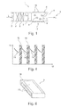
- FIG. 1 an automotive air conditioning system is shown in a schematic cross-sectional view.
- the motor vehicle kiln system 1 is shown in a greatly simplifying view, which essentially concentrates on the areas which are related to the air treatment by ionization of the air flow L to be processed by the motor vehicle air conditioning system 1.
- the sucked by the motor vehicle air conditioner 1 by means of a blower 2 air L is first passed through a filter 3, in the pollen, dirt particles and the like which may be contained in the ambient air, have been filtered out. Subsequently, the air flow L is passed through a radiator 4 and tempered accordingly (of course, the temperature can also be done by a mixture of hot and cold air, moreover, the air can also be cooled by means of an evaporator, etc.).
- the already largely conditioned air flow L is, before it is released via a Lucasausströmerdüse 6 in a Kraftfährzeuginnenraum 5, first passed through an ionization module 7.
- anions 8 are generated, which are perceived by the vehicle occupants as "fresh air".
- the anions 8 generated by the ionization module 7 must first be passed through correspondingly shaped air guide channels 9 and flow through the air outlet nozzle 6. In this case, some of the anions 8 generated by the ionization module 7 strike the walls of the air duct 9 or the air vent nozzle 6 and deliver their charge to the corresponding edge region 10. Over time, this leads to an electrostatic charge of certain wall regions 10 of the air guide element 9 and the air outlet nozzle 6. However, the electrostatic charge of the corresponding wall regions 10 is not uniform, so that electric fields occur between wall regions 10 charged to different degrees. The electric fields again affect the air flow L (In particular, the ions contained in the air flow L), in particular the trajectory of the anions 8, so that the system behaves extremely dynamic and difficult to predict.
- the ionization module 7 would have to generate a correspondingly larger number of anions 8.
- the ionization module 7 would have to be designed to be correspondingly larger (which would make it more expensive and heavier), and correspondingly more electrical energy would have to be made available for the ionization module 7.
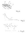
- the decrease in the concentration of released into the motor vehicle interior 5 anions 8 is in Fig. 2 shown schematically as a function graph 11 (unless separate measures, such as special operating procedures and / or constructive measures are taken). In Fig.
- Fig. 1 indicated arrangement of a grid 17 of spaced metal foils 18.
- Possible details of the position and arrangement of the metal foils 18 on the air duct 9 are also in Fig. 5 to recognize.
- a regular grid of similarly shaped metal foils 18 is used.
- the individual “columns" of the grid are in each case offset relative to one another, so that the metal foils 18 are to some extent arranged "against each other" in a gap.
- the metal foils 18 are formed as self-adhesive metal foils, and are glued, for example, on the already finished air duct 9 (which was made of plastic for example by means of an injection molding process).
- the metal foils 18 are on the outside 19 of the air duct 9.
- the metal foils 18 are each disposed electrically isolated from each other and also not grounded. In a further conceivable embodiment, it is also possible for the (or a part of) the metal foils 18 to be electrically connected to one another (possibly upper high-resistance electrical conductors) and / or (optionally via a high-resistance electrical conductor) to earth potential.
- the localized mobility of charge carriers in the individual metal foils 18 causes mirror charges to form in the metal foils 18 over a limited distance, leading to electric landings or charge clusters at the inner wall regions 10 and 10 / or in the interior of the air duct 9 can correspond.
- the mirror charges formed thereby cause a reduction or advantageous redistribution of the existing electric fields, which ultimately leads to a higher proportion through the air duct 9 passing through anions 8 can lead (without these going to the wall portions 10 of the air duct 9 and the Heilausströmerelements 6 lost). Thereby, the exit of anions 8 in the motor vehicle interior 5 can be improved.
- FIG. 6 Another possible embodiment for a device that effects such a locally acting field compensation is in Fig. 6 presented.
- an air duct 9 is shown in a schematic perspective view.
- ESD foils 20 are provided on the outer sides 19 of the air duct 9 are mounted over a large area.
- the ESD foils 20 are formed in the present embodiment illustrated as self-adhesive films, which are adhered to the finished air duct 9. Due to the poor electrical conductivity in relation to metal foils - in relation to electrical insulators, however, good electrical conductivity - here also effectively results in a local compensation occurring electric fields, which compensation occurs only in a relatively narrow area.
- the ESD filler 20 has only a low longitudinal conductivity. This low longitudinal conductivity allows a locally greatly varying image charge (even over short distances), or makes the only small L jossleitfählgkeit it possible that locally very different surface charges can be dissipated. Also in the presently illustrated embodiment of Fig. 6 is it possible that the individual ESD foils 20 (possibly high-resistance) are electrically connected to one another and / or (if appropriate via high-resistance connecting lines) connected to ground.
- the ionization module 7 in order to increase the concentration of anions 8 released in the motor vehicle interior 5 on an average time basis, it is possible to operate the ionization module 7 only in a normal operating mode 14 over a certain period of time (typically 1 to 3 minutes) (compare with FIG Fig. 3 ). After a certain period of time, the motor vehicle air conditioning system 1 is switched to a regeneration mode 15 in which not only anions 8 (as in FIG Fig. 1 shown) are generated, but in addition also cations of the ionization module 7 (which must be designed accordingly for this purpose) are generated.
- a regeneration mode 15 in which not only anions 8 (as in FIG Fig. 1 shown) are generated, but in addition also cations of the ionization module 7 (which must be designed accordingly for this purpose) are generated.
- the cations generated by the ionization module 7 are only “temporarily” generated in the present embodiment and are only used to generate a second type of ion, which in the present case are also anions 8 (although of a different ion type).
- the "alternately” generation of different types of ions leads to a discharge of the statically charged wall regions 10, so that thanks to the regeneration phase 15, the concentration of the in the motor vehicle interior Not only does it not decrease further, but on the contrary, it can increase again.
- a normal operating mode 14 again follows, which in turn is followed by a regeneration mode 15, etc. This procedure is in Fig. 3 shown. Again, the time is shown along the abscissa 12, whereas along the ordinate 13, the concentration of the released into the motor vehicle interior 5 anions is shown.
- a second possible method for controlling an ionization module 7 is then that the ionization module 7 - analogously to the previous embodiment - is first operated in a normal operating mode 14 (see Fig. 4 ). After a certain period of time (typically 1 to 3 minutes), the ionization module 7 is regenerated 16 in that the ionization module 7 is simply switched off, and thus no ions (in particular no anions 8) are generated. In this regeneration phase 16, the static charges along the wall portions 10 of the air duct 9 and the Lucasausströmerdüse 6 can also degrade, for example, by the usually located in the air flow L moisture. The duration of the regeneration phase is typically 5 to 30 seconds.
Claims (10)
- Dispositif de guidage d'air (6, 9), en particulier conduit de guidage d'air (9) et / ou buse de sortie d'air (6), de préférence dispositif de guidage d'air (6, 9) pour un dispositif d'ionisation (7), où des moyens de compensation de champ (18, 20) agissant localement sont appliqués sur le dispositif de guidage d'air, caractérisé en ce que les moyens de compensation de champ (18, 20) présentent une trame régulière de feuilles de métal (18) formées de façon identique, espacées à chaque fois les unes des autres et disposées en étant décalées les unes par rapport aux autres, ou bien présentent des feuilles ESD (20) appliquées sur une grande étendue du dispositif de guidage d'air.
- Dispositif de guidage d'air (6, 9) selon la revendication 1, caractérisé en ce que la conductivité électrique d'au moins une feuille de métal (18) est supérieure ou égale à 104 S/m, à 105 S/m et / ou à 106 S/m.
- Dispositif de guidage d'air (6, 9) selon la revendication 1 ou 2, caractérisé en ce qu'au moins deux moyens de compensation de champ (18, 20) agissant localement, en particulier au moins deux feuilles de métal (18), sont découplés électriquement l'un de l'autre.
- Dispositif de guidage d'air (6, 9) selon la revendication 3, caractérisé en ce que le découplage électrique présente au moins partiellement une conductivité électrique inférieure ou égale à 105 S/m, à 104 S/m, à 103 S/m, à 102 S/m, 101 S/m et / ou à 10° S/m.
- Dispositif de guidage d'air (6, 9) selon l'une quelconque des revendications précédentes, caractérisé en ce qu'au moins une feuille ESD (20) présente au moins partiellement une conductivité électrique inférieure ou égale à 105 S/m, à 104 S/m, à 103 S/m, à 102 S/m, à 101 S/m, à 100 S/m, à 10-1 S/m, à 10-2 S/m, à 10-3 S/m, à 10-4 S/m et / ou à 10-5 S/m.
- Dispositif de guidage d'air (6, 9) selon l'une quelconque des revendications précédentes, caractérisé en ce qu'au moins un moyen de compensation de champ (18, 20) agissant localement, en particulier au moins une partie de matière (18) électriquement conductrice et / ou au moins une feuille ESD (20), est réalisé de façon autoadhésive.
- Dispositif d'ionisation présentant au moins un premier moyen d'ionisation (7) servant à la libération d'ions (8) d'un premier type d'ions, se produisant au moins par moments, ainsi qu'au moins un dispositif de guidage d'air (6, 9) selon l'une quelconque des revendications 1 à 6, où le dispositif de guidage d'air est disposé en aval du moyen d'ionisation (7).
- Dispositif d'ionisation selon la revendication 7, qui est conçu et agencé de manière telle, que celui-ci puisse être actionné au moins par moments, dans au moins un mode de régénération (15, 16).
- Dispositif d'ionisation selon la revendication 8, caractérisé en ce que dans le mode de régénération (15, 16) au moins au nombre de un sont libérés, au moins par moments, des ions (8) d'un second type d'ions différent du premier type d'ions et / ou, au moins par moments, aucun ion (8) n'est libéré, en particulier aucun ion du premier type d'ions.
- Système de climatisation (1), en particulier système de climatisation d'un véhicule automobile, caractérisé par au moins un dispositif de guidage d'air (6, 9) selon l'une quelconque des revendications 1 à 6, et / ou par au moins un dispositif d'ionisation selon l'une quelconque des revendications 7 à 9.
Applications Claiming Priority (2)
| Application Number | Priority Date | Filing Date | Title |
|---|---|---|---|
| DE102009038298A DE102009038298A1 (de) | 2009-08-21 | 2009-08-21 | Luftführungskanal für Ionisierungsvorrichtung |
| PCT/EP2010/061500 WO2011020717A1 (fr) | 2009-08-21 | 2010-08-06 | Conduit d'air pour dispositif d'ionisation |
Publications (2)
| Publication Number | Publication Date |
|---|---|
| EP2467274A1 EP2467274A1 (fr) | 2012-06-27 |
| EP2467274B1 true EP2467274B1 (fr) | 2015-07-29 |
Family
ID=42768074
Family Applications (1)
| Application Number | Title | Priority Date | Filing Date |
|---|---|---|---|
| EP10742476.4A Not-in-force EP2467274B1 (fr) | 2009-08-21 | 2010-08-06 | Conduit d'air pour appareil d'ionisation |
Country Status (5)
| Country | Link |
|---|---|
| US (1) | US20120214395A1 (fr) |
| EP (1) | EP2467274B1 (fr) |
| KR (1) | KR20120090986A (fr) |
| DE (1) | DE102009038298A1 (fr) |
| WO (1) | WO2011020717A1 (fr) |
Families Citing this family (7)
| Publication number | Priority date | Publication date | Assignee | Title |
|---|---|---|---|---|
| DE102013108653A1 (de) * | 2013-08-09 | 2015-02-12 | Dr. Schneider Kunststoffwerke Gmbh | Steuereinheit |
| JP6078606B1 (ja) * | 2015-09-30 | 2017-02-08 | 富士重工業株式会社 | 自動車用空調装置 |
| DE102016000319B4 (de) * | 2016-01-13 | 2017-09-28 | Audi Ag | Ionisationsvorrichtung und korrespondierende Belüftungsanordnung |
| DE102016000666B4 (de) * | 2016-01-22 | 2017-09-28 | Audi Ag | Ionisationsvorrichtung und korrespondierende Belüftungsanordnung |
| DE102016008900B4 (de) | 2016-07-22 | 2020-08-06 | Audi Ag | Belüftungsanordnung mit einer Ionisationsvorrichtung für ein Fahrzeug |
| CN107672417A (zh) * | 2017-11-22 | 2018-02-09 | 科成精密模塑科技无锡有限公司 | 车载空调精密模塑面板及其过滤系统 |
| DE102018215201A1 (de) * | 2018-09-07 | 2020-03-12 | Bayerische Motoren Werke Aktiengesellschaft | Lüftungssystem für einen Fahrzeuginnenraum |
Family Cites Families (20)
| Publication number | Priority date | Publication date | Assignee | Title |
|---|---|---|---|---|
| ES195976Y (es) * | 1973-05-02 | 1975-07-01 | Craf Von Berckheim | Electrodo autoadhesivo para una instalacion de climatiza- cion electrica. |
| US5153811A (en) * | 1991-08-28 | 1992-10-06 | Itw, Inc. | Self-balancing ionizing circuit for static eliminators |
| DE19651402A1 (de) * | 1996-12-11 | 1998-06-18 | T E M Tech Entwicklung Und Man | Apparat zur physikalischen Aufbereitung von Luft, insbesondere von Atemluft |
| DE19919623A1 (de) * | 1999-04-29 | 2000-11-02 | T E M Tech Entwicklungen Und M | Luftaufbereitungssystem zum wirksamen Abbau von luftgetragenen Gerüchen, Keimen und Schadstoffen |
| JP4413445B2 (ja) * | 2001-03-19 | 2010-02-10 | 三菱電機株式会社 | 空調ダクト装置 |
| DE10163201A1 (de) * | 2001-12-21 | 2003-07-10 | Behr Gmbh & Co | Heizungs- oder Klimaanlage insbesondere für ein Kraftfahrzeug |
| JP2004079471A (ja) | 2002-08-22 | 2004-03-11 | Denso Corp | マイナスイオン発生装置 |
| US6826030B2 (en) * | 2002-09-20 | 2004-11-30 | Illinois Tool Works Inc. | Method of offset voltage control for bipolar ionization systems |
| DE10255858A1 (de) * | 2002-11-29 | 2004-06-17 | Evotec Oai Ag | Fluidisches Mikrosystem mit feldformenden Passivierungsschichten auf Mikroelektroden |
| JP4059070B2 (ja) * | 2002-12-04 | 2008-03-12 | 日産自動車株式会社 | イオン発生装置付き車両用空調装置 |
| US6985346B2 (en) * | 2003-01-29 | 2006-01-10 | Credence Technologies, Inc. | Method and device for controlling ionization |
| GB2406222B (en) * | 2003-09-22 | 2007-03-21 | Meech Static Eliminators Ltd | Electrical ioniser |
| WO2007018575A2 (fr) * | 2004-11-12 | 2007-02-15 | Thorrn Micro Technologies, Inc. | Production d'ions par commande temporelle du claquage dielectrique gazeux |
| JP4418778B2 (ja) * | 2005-06-17 | 2010-02-24 | 清水建設株式会社 | 気体搬送用ダクトの接続構造 |
| US20070103842A1 (en) * | 2005-11-03 | 2007-05-10 | Mks Instruments, Inc. | AC Ionizer with Enhanced Ion Balance |
| DE102005054961A1 (de) * | 2005-11-17 | 2007-05-24 | Audi Ag | Luftkanal für eine Kraftfahrzeug-Karosserie und Rohbaustruktur einer Kraftfahrzeugkarosserie |
| US7911146B2 (en) * | 2006-05-31 | 2011-03-22 | The Regents Of The University Of California | High-velocity, multistage, nozzled, ion driven wind generator and method of operation of the same adaptable to mesoscale realization |
| EP2183796A2 (fr) * | 2007-08-03 | 2010-05-12 | Battelle Memorial Institute | Dispositif thermoélectrique et matériau thermoélectrique |
| WO2009045430A1 (fr) | 2007-10-04 | 2009-04-09 | E.I.Du Pont De Nemours And Company | Canalisations d'air pour véhicules |
| CN101738429B (zh) * | 2008-11-26 | 2013-04-03 | 岛津分析技术研发(上海)有限公司 | 离子分离、富集与检测装置 |
-
2009
- 2009-08-21 DE DE102009038298A patent/DE102009038298A1/de not_active Withdrawn
-
2010
- 2010-08-06 KR KR1020127007370A patent/KR20120090986A/ko not_active Application Discontinuation
- 2010-08-06 WO PCT/EP2010/061500 patent/WO2011020717A1/fr active Application Filing
- 2010-08-06 EP EP10742476.4A patent/EP2467274B1/fr not_active Not-in-force
-
2012
- 2012-02-21 US US13/401,378 patent/US20120214395A1/en not_active Abandoned
Also Published As
| Publication number | Publication date |
|---|---|
| WO2011020717A1 (fr) | 2011-02-24 |
| KR20120090986A (ko) | 2012-08-17 |
| EP2467274A1 (fr) | 2012-06-27 |
| US20120214395A1 (en) | 2012-08-23 |
| DE102009038298A1 (de) | 2011-03-24 |
Similar Documents
| Publication | Publication Date | Title |
|---|---|---|
| EP2467274B1 (fr) | Conduit d'air pour appareil d'ionisation | |
| EP2467273B2 (fr) | Procédé de controle d'un appareil d'ionisation | |
| DE19859588C2 (de) | Negativionen-Erzeugungsvorrichtung | |
| DD257590A5 (de) | Anordnung zur erzeugung einer elektrischen koronaentladung in der luft | |
| DE102011116246B4 (de) | Sekundartransformatoreinheit zur Anbringung an einem Fahrzeug mit Elektroantrieb und Fahrzeug mit Elektroantrieb | |
| DE102017118652A1 (de) | Plasmageneratormodul und dessen Verwendung | |
| WO2014206951A1 (fr) | Dispositif de chauffage électrique et procédé permettant de produire un dispositif de chauffage électrique | |
| DE3700362C2 (fr) | ||
| DE102008049278A1 (de) | Mehrzonenklimaanlage | |
| EP1961594A2 (fr) | Conduit d'air, notamment pour un véhicule automobile | |
| DE102016004857A1 (de) | Verfahren zum Reinigen der Luft eines Fahrgastraums eines Fahrzeugs | |
| DE10317514B3 (de) | Klimaanlage | |
| CH713662A2 (de) | Pulversprühkopf und Pulverbeschichtungsanlage mit einem solchen. | |
| DE102008049280A1 (de) | Ionisationsvorrichtung | |
| WO2010043246A1 (fr) | Procédé pour générer un flux d'ions dans un appareil de mise en forme ou de soins des cheveux | |
| DE102019101885A1 (de) | Elektroabscheider in Stufenform | |
| DE102017121192A1 (de) | Fahrzeugklimaanlagen-Auslasseinheit | |
| DE2555547B2 (de) | Vorrichtung zum elektrostatischen Auftragen bzw. Aufsprühen von Materialteilchen | |
| DE19904607C1 (de) | Denaturierendes Kaskaden-Elektrofiltersystem mit mindestens zwei Filterstufen | |
| DE112020007875T5 (de) | Luftreinigungsvorrichtung mit einer UV-Lichtquelle | |
| DE102021125570A1 (de) | Raumluftreiniger mit Ozonkatalysator | |
| DE102012012286B4 (de) | "lonisierungsvorrichtung zur Anreicherung eines Luftstroms mit negativ geladenen lonen" | |
| WO2023010148A1 (fr) | Dispositif de purification pour purifier un gaz | |
| WO2024068787A1 (fr) | Purificateur d'air ambiant | |
| DE2508166A1 (de) | Vorrichtung und verfahren zur anreicherung eines luftstromes mit ionen |
Legal Events
| Date | Code | Title | Description |
|---|---|---|---|
| PUAI | Public reference made under article 153(3) epc to a published international application that has entered the european phase |
Free format text: ORIGINAL CODE: 0009012 |
|
| 17P | Request for examination filed |
Effective date: 20120321 |
|
| AK | Designated contracting states |
Kind code of ref document: A1 Designated state(s): AL AT BE BG CH CY CZ DE DK EE ES FI FR GB GR HR HU IE IS IT LI LT LU LV MC MK MT NL NO PL PT RO SE SI SK SM TR |
|
| DAX | Request for extension of the european patent (deleted) | ||
| 17Q | First examination report despatched |
Effective date: 20131030 |
|
| GRAP | Despatch of communication of intention to grant a patent |
Free format text: ORIGINAL CODE: EPIDOSNIGR1 |
|
| RAP1 | Party data changed (applicant data changed or rights of an application transferred) |
Owner name: MAHLE BEHR GMBH & CO. KG |
|
| INTG | Intention to grant announced |
Effective date: 20150310 |
|
| GRAS | Grant fee paid |
Free format text: ORIGINAL CODE: EPIDOSNIGR3 |
|
| GRAA | (expected) grant |
Free format text: ORIGINAL CODE: 0009210 |
|
| AK | Designated contracting states |
Kind code of ref document: B1 Designated state(s): AL AT BE BG CH CY CZ DE DK EE ES FI FR GB GR HR HU IE IS IT LI LT LU LV MC MK MT NL NO PL PT RO SE SI SK SM TR |
|
| REG | Reference to a national code |
Ref country code: GB Ref legal event code: FG4D Free format text: NOT ENGLISH |
|
| REG | Reference to a national code |
Ref country code: CH Ref legal event code: EP |
|
| REG | Reference to a national code |
Ref country code: AT Ref legal event code: REF Ref document number: 738962 Country of ref document: AT Kind code of ref document: T Effective date: 20150815 |
|
| REG | Reference to a national code |
Ref country code: FR Ref legal event code: PLFP Year of fee payment: 6 |
|
| REG | Reference to a national code |
Ref country code: IE Ref legal event code: FG4D Free format text: LANGUAGE OF EP DOCUMENT: GERMAN |
|
| REG | Reference to a national code |
Ref country code: DE Ref legal event code: R096 Ref document number: 502010009963 Country of ref document: DE |
|
| REG | Reference to a national code |
Ref country code: LT Ref legal event code: MG4D |
|
| REG | Reference to a national code |
Ref country code: NL Ref legal event code: MP Effective date: 20150729 |
|
| PG25 | Lapsed in a contracting state [announced via postgrant information from national office to epo] |
Ref country code: LT Free format text: LAPSE BECAUSE OF FAILURE TO SUBMIT A TRANSLATION OF THE DESCRIPTION OR TO PAY THE FEE WITHIN THE PRESCRIBED TIME-LIMIT Effective date: 20150729 Ref country code: FI Free format text: LAPSE BECAUSE OF FAILURE TO SUBMIT A TRANSLATION OF THE DESCRIPTION OR TO PAY THE FEE WITHIN THE PRESCRIBED TIME-LIMIT Effective date: 20150729 Ref country code: GR Free format text: LAPSE BECAUSE OF FAILURE TO SUBMIT A TRANSLATION OF THE DESCRIPTION OR TO PAY THE FEE WITHIN THE PRESCRIBED TIME-LIMIT Effective date: 20151030 Ref country code: LV Free format text: LAPSE BECAUSE OF FAILURE TO SUBMIT A TRANSLATION OF THE DESCRIPTION OR TO PAY THE FEE WITHIN THE PRESCRIBED TIME-LIMIT Effective date: 20150729 Ref country code: NO Free format text: LAPSE BECAUSE OF FAILURE TO SUBMIT A TRANSLATION OF THE DESCRIPTION OR TO PAY THE FEE WITHIN THE PRESCRIBED TIME-LIMIT Effective date: 20151029 |
|
| PG25 | Lapsed in a contracting state [announced via postgrant information from national office to epo] |
Ref country code: PT Free format text: LAPSE BECAUSE OF FAILURE TO SUBMIT A TRANSLATION OF THE DESCRIPTION OR TO PAY THE FEE WITHIN THE PRESCRIBED TIME-LIMIT Effective date: 20151130 Ref country code: HR Free format text: LAPSE BECAUSE OF FAILURE TO SUBMIT A TRANSLATION OF THE DESCRIPTION OR TO PAY THE FEE WITHIN THE PRESCRIBED TIME-LIMIT Effective date: 20150729 Ref country code: SE Free format text: LAPSE BECAUSE OF FAILURE TO SUBMIT A TRANSLATION OF THE DESCRIPTION OR TO PAY THE FEE WITHIN THE PRESCRIBED TIME-LIMIT Effective date: 20150729 Ref country code: IS Free format text: LAPSE BECAUSE OF FAILURE TO SUBMIT A TRANSLATION OF THE DESCRIPTION OR TO PAY THE FEE WITHIN THE PRESCRIBED TIME-LIMIT Effective date: 20151129 Ref country code: PL Free format text: LAPSE BECAUSE OF FAILURE TO SUBMIT A TRANSLATION OF THE DESCRIPTION OR TO PAY THE FEE WITHIN THE PRESCRIBED TIME-LIMIT Effective date: 20150729 Ref country code: ES Free format text: LAPSE BECAUSE OF FAILURE TO SUBMIT A TRANSLATION OF THE DESCRIPTION OR TO PAY THE FEE WITHIN THE PRESCRIBED TIME-LIMIT Effective date: 20150729 |
|
| PG25 | Lapsed in a contracting state [announced via postgrant information from national office to epo] |
Ref country code: NL Free format text: LAPSE BECAUSE OF FAILURE TO SUBMIT A TRANSLATION OF THE DESCRIPTION OR TO PAY THE FEE WITHIN THE PRESCRIBED TIME-LIMIT Effective date: 20150729 |
|
| REG | Reference to a national code |
Ref country code: CH Ref legal event code: PL |
|
| PG25 | Lapsed in a contracting state [announced via postgrant information from national office to epo] |
Ref country code: MC Free format text: LAPSE BECAUSE OF FAILURE TO SUBMIT A TRANSLATION OF THE DESCRIPTION OR TO PAY THE FEE WITHIN THE PRESCRIBED TIME-LIMIT Effective date: 20150729 Ref country code: IT Free format text: LAPSE BECAUSE OF FAILURE TO SUBMIT A TRANSLATION OF THE DESCRIPTION OR TO PAY THE FEE WITHIN THE PRESCRIBED TIME-LIMIT Effective date: 20150729 Ref country code: CZ Free format text: LAPSE BECAUSE OF FAILURE TO SUBMIT A TRANSLATION OF THE DESCRIPTION OR TO PAY THE FEE WITHIN THE PRESCRIBED TIME-LIMIT Effective date: 20150729 Ref country code: CH Free format text: LAPSE BECAUSE OF NON-PAYMENT OF DUE FEES Effective date: 20150831 Ref country code: EE Free format text: LAPSE BECAUSE OF FAILURE TO SUBMIT A TRANSLATION OF THE DESCRIPTION OR TO PAY THE FEE WITHIN THE PRESCRIBED TIME-LIMIT Effective date: 20150729 Ref country code: LI Free format text: LAPSE BECAUSE OF NON-PAYMENT OF DUE FEES Effective date: 20150831 Ref country code: SK Free format text: LAPSE BECAUSE OF FAILURE TO SUBMIT A TRANSLATION OF THE DESCRIPTION OR TO PAY THE FEE WITHIN THE PRESCRIBED TIME-LIMIT Effective date: 20150729 Ref country code: DK Free format text: LAPSE BECAUSE OF FAILURE TO SUBMIT A TRANSLATION OF THE DESCRIPTION OR TO PAY THE FEE WITHIN THE PRESCRIBED TIME-LIMIT Effective date: 20150729 |
|
| REG | Reference to a national code |
Ref country code: DE Ref legal event code: R097 Ref document number: 502010009963 Country of ref document: DE |
|
| PG25 | Lapsed in a contracting state [announced via postgrant information from national office to epo] |
Ref country code: RO Free format text: LAPSE BECAUSE OF FAILURE TO SUBMIT A TRANSLATION OF THE DESCRIPTION OR TO PAY THE FEE WITHIN THE PRESCRIBED TIME-LIMIT Effective date: 20150729 |
|
| REG | Reference to a national code |
Ref country code: IE Ref legal event code: MM4A |
|
| PLBE | No opposition filed within time limit |
Free format text: ORIGINAL CODE: 0009261 |
|
| STAA | Information on the status of an ep patent application or granted ep patent |
Free format text: STATUS: NO OPPOSITION FILED WITHIN TIME LIMIT |
|
| GBPC | Gb: european patent ceased through non-payment of renewal fee |
Effective date: 20151029 |
|
| 26N | No opposition filed |
Effective date: 20160502 |
|
| PG25 | Lapsed in a contracting state [announced via postgrant information from national office to epo] |
Ref country code: IE Free format text: LAPSE BECAUSE OF NON-PAYMENT OF DUE FEES Effective date: 20150806 Ref country code: GB Free format text: LAPSE BECAUSE OF NON-PAYMENT OF DUE FEES Effective date: 20151029 |
|
| REG | Reference to a national code |
Ref country code: FR Ref legal event code: PLFP Year of fee payment: 7 |
|
| PG25 | Lapsed in a contracting state [announced via postgrant information from national office to epo] |
Ref country code: SI Free format text: LAPSE BECAUSE OF FAILURE TO SUBMIT A TRANSLATION OF THE DESCRIPTION OR TO PAY THE FEE WITHIN THE PRESCRIBED TIME-LIMIT Effective date: 20150729 |
|
| REG | Reference to a national code |
Ref country code: AT Ref legal event code: MM01 Ref document number: 738962 Country of ref document: AT Kind code of ref document: T Effective date: 20150806 |
|
| PG25 | Lapsed in a contracting state [announced via postgrant information from national office to epo] |
Ref country code: AT Free format text: LAPSE BECAUSE OF NON-PAYMENT OF DUE FEES Effective date: 20150806 |
|
| PG25 | Lapsed in a contracting state [announced via postgrant information from national office to epo] |
Ref country code: MT Free format text: LAPSE BECAUSE OF FAILURE TO SUBMIT A TRANSLATION OF THE DESCRIPTION OR TO PAY THE FEE WITHIN THE PRESCRIBED TIME-LIMIT Effective date: 20150729 |
|
| PG25 | Lapsed in a contracting state [announced via postgrant information from national office to epo] |
Ref country code: SM Free format text: LAPSE BECAUSE OF FAILURE TO SUBMIT A TRANSLATION OF THE DESCRIPTION OR TO PAY THE FEE WITHIN THE PRESCRIBED TIME-LIMIT Effective date: 20150729 Ref country code: HU Free format text: LAPSE BECAUSE OF FAILURE TO SUBMIT A TRANSLATION OF THE DESCRIPTION OR TO PAY THE FEE WITHIN THE PRESCRIBED TIME-LIMIT; INVALID AB INITIO Effective date: 20100806 Ref country code: BG Free format text: LAPSE BECAUSE OF FAILURE TO SUBMIT A TRANSLATION OF THE DESCRIPTION OR TO PAY THE FEE WITHIN THE PRESCRIBED TIME-LIMIT Effective date: 20150729 |
|
| PG25 | Lapsed in a contracting state [announced via postgrant information from national office to epo] |
Ref country code: CY Free format text: LAPSE BECAUSE OF FAILURE TO SUBMIT A TRANSLATION OF THE DESCRIPTION OR TO PAY THE FEE WITHIN THE PRESCRIBED TIME-LIMIT Effective date: 20150729 |
|
| PG25 | Lapsed in a contracting state [announced via postgrant information from national office to epo] |
Ref country code: BE Free format text: LAPSE BECAUSE OF NON-PAYMENT OF DUE FEES Effective date: 20150831 |
|
| REG | Reference to a national code |
Ref country code: FR Ref legal event code: PLFP Year of fee payment: 8 |
|
| PG25 | Lapsed in a contracting state [announced via postgrant information from national office to epo] |
Ref country code: TR Free format text: LAPSE BECAUSE OF FAILURE TO SUBMIT A TRANSLATION OF THE DESCRIPTION OR TO PAY THE FEE WITHIN THE PRESCRIBED TIME-LIMIT Effective date: 20150729 |
|
| PG25 | Lapsed in a contracting state [announced via postgrant information from national office to epo] |
Ref country code: LU Free format text: LAPSE BECAUSE OF NON-PAYMENT OF DUE FEES Effective date: 20150806 |
|
| PG25 | Lapsed in a contracting state [announced via postgrant information from national office to epo] |
Ref country code: MK Free format text: LAPSE BECAUSE OF FAILURE TO SUBMIT A TRANSLATION OF THE DESCRIPTION OR TO PAY THE FEE WITHIN THE PRESCRIBED TIME-LIMIT Effective date: 20150729 |
|
| REG | Reference to a national code |
Ref country code: FR Ref legal event code: PLFP Year of fee payment: 9 |
|
| PG25 | Lapsed in a contracting state [announced via postgrant information from national office to epo] |
Ref country code: AL Free format text: LAPSE BECAUSE OF FAILURE TO SUBMIT A TRANSLATION OF THE DESCRIPTION OR TO PAY THE FEE WITHIN THE PRESCRIBED TIME-LIMIT Effective date: 20150729 |
|
| PGFP | Annual fee paid to national office [announced via postgrant information from national office to epo] |
Ref country code: DE Payment date: 20180831 Year of fee payment: 9 Ref country code: FR Payment date: 20180823 Year of fee payment: 9 |
|
| REG | Reference to a national code |
Ref country code: DE Ref legal event code: R119 Ref document number: 502010009963 Country of ref document: DE |
|
| PG25 | Lapsed in a contracting state [announced via postgrant information from national office to epo] |
Ref country code: DE Free format text: LAPSE BECAUSE OF NON-PAYMENT OF DUE FEES Effective date: 20200303 Ref country code: FR Free format text: LAPSE BECAUSE OF NON-PAYMENT OF DUE FEES Effective date: 20190831 |