EP2467273B2 - Procédé de controle d'un appareil d'ionisation - Google Patents
Procédé de controle d'un appareil d'ionisation Download PDFInfo
- Publication number
- EP2467273B2 EP2467273B2 EP10742473.1A EP10742473A EP2467273B2 EP 2467273 B2 EP2467273 B2 EP 2467273B2 EP 10742473 A EP10742473 A EP 10742473A EP 2467273 B2 EP2467273 B2 EP 2467273B2
- Authority
- EP
- European Patent Office
- Prior art keywords
- air
- ions
- conditioning system
- intermittently
- ion type
- Prior art date
- Legal status (The legal status is an assumption and is not a legal conclusion. Google has not performed a legal analysis and makes no representation as to the accuracy of the status listed.)
- Not-in-force
Links
- 238000000034 method Methods 0.000 title claims description 26
- 150000002500 ions Chemical class 0.000 claims description 118
- 238000011069 regeneration method Methods 0.000 claims description 42
- 230000008929 regeneration Effects 0.000 claims description 41
- 238000004378 air conditioning Methods 0.000 claims description 28
- 230000005684 electric field Effects 0.000 claims description 12
- 239000004020 conductor Substances 0.000 claims description 9
- 238000009423 ventilation Methods 0.000 claims description 8
- 239000000853 adhesive Substances 0.000 claims description 5
- 238000013461 design Methods 0.000 claims description 5
- 239000003570 air Substances 0.000 description 84
- 150000001450 anions Chemical class 0.000 description 23
- 239000011888 foil Substances 0.000 description 18
- 239000002184 metal Substances 0.000 description 15
- 150000001768 cations Chemical class 0.000 description 6
- 239000003795 chemical substances by application Substances 0.000 description 6
- 230000009467 reduction Effects 0.000 description 6
- 238000002474 experimental method Methods 0.000 description 3
- 239000000463 material Substances 0.000 description 3
- 239000000203 mixture Substances 0.000 description 3
- 239000002800 charge carrier Substances 0.000 description 2
- 230000001143 conditioned effect Effects 0.000 description 2
- 238000010276 construction Methods 0.000 description 2
- 238000009826 distribution Methods 0.000 description 2
- 230000000694 effects Effects 0.000 description 2
- 239000012799 electrically-conductive coating Substances 0.000 description 2
- 235000019645 odor Nutrition 0.000 description 2
- 238000011017 operating method Methods 0.000 description 2
- 239000001301 oxygen Substances 0.000 description 2
- 229910052760 oxygen Inorganic materials 0.000 description 2
- 244000052769 pathogen Species 0.000 description 2
- 230000003068 static effect Effects 0.000 description 2
- 238000012549 training Methods 0.000 description 2
- 241000894006 Bacteria Species 0.000 description 1
- 241000700605 Viruses Species 0.000 description 1
- 230000035508 accumulation Effects 0.000 description 1
- 238000009825 accumulation Methods 0.000 description 1
- 230000009471 action Effects 0.000 description 1
- 239000002313 adhesive film Substances 0.000 description 1
- 239000012080 ambient air Substances 0.000 description 1
- 230000000844 anti-bacterial effect Effects 0.000 description 1
- QVGXLLKOCUKJST-UHFFFAOYSA-N atomic oxygen Chemical compound [O] QVGXLLKOCUKJST-UHFFFAOYSA-N 0.000 description 1
- 230000015572 biosynthetic process Effects 0.000 description 1
- 238000004140 cleaning Methods 0.000 description 1
- 239000011248 coating agent Substances 0.000 description 1
- 238000000576 coating method Methods 0.000 description 1
- 238000001816 cooling Methods 0.000 description 1
- 239000011162 core material Substances 0.000 description 1
- 238000011161 development Methods 0.000 description 1
- 230000018109 developmental process Effects 0.000 description 1
- 239000000428 dust Substances 0.000 description 1
- 239000007789 gas Substances 0.000 description 1
- 238000010438 heat treatment Methods 0.000 description 1
- 238000013101 initial test Methods 0.000 description 1
- 238000001746 injection moulding Methods 0.000 description 1
- 238000003780 insertion Methods 0.000 description 1
- 230000037431 insertion Effects 0.000 description 1
- 238000006386 neutralization reaction Methods 0.000 description 1
- 239000000615 nonconductor Substances 0.000 description 1
- 229920000620 organic polymer Polymers 0.000 description 1
- -1 oxygen ions Chemical class 0.000 description 1
- 239000002245 particle Substances 0.000 description 1
- 238000010926 purge Methods 0.000 description 1
- 230000003134 recirculating effect Effects 0.000 description 1
- 239000000243 solution Substances 0.000 description 1
- 230000001960 triggered effect Effects 0.000 description 1
- XLYOFNOQVPJJNP-UHFFFAOYSA-N water Substances O XLYOFNOQVPJJNP-UHFFFAOYSA-N 0.000 description 1
Images

Classifications
-
- B—PERFORMING OPERATIONS; TRANSPORTING
- B60—VEHICLES IN GENERAL
- B60H—ARRANGEMENTS OF HEATING, COOLING, VENTILATING OR OTHER AIR-TREATING DEVICES SPECIALLY ADAPTED FOR PASSENGER OR GOODS SPACES OF VEHICLES
- B60H3/00—Other air-treating devices
- B60H3/0071—Electrically conditioning the air, e.g. by ionizing
-
- B—PERFORMING OPERATIONS; TRANSPORTING
- B60—VEHICLES IN GENERAL
- B60H—ARRANGEMENTS OF HEATING, COOLING, VENTILATING OR OTHER AIR-TREATING DEVICES SPECIALLY ADAPTED FOR PASSENGER OR GOODS SPACES OF VEHICLES
- B60H3/00—Other air-treating devices
-
- A—HUMAN NECESSITIES
- A61—MEDICAL OR VETERINARY SCIENCE; HYGIENE
- A61L—METHODS OR APPARATUS FOR STERILISING MATERIALS OR OBJECTS IN GENERAL; DISINFECTION, STERILISATION OR DEODORISATION OF AIR; CHEMICAL ASPECTS OF BANDAGES, DRESSINGS, ABSORBENT PADS OR SURGICAL ARTICLES; MATERIALS FOR BANDAGES, DRESSINGS, ABSORBENT PADS OR SURGICAL ARTICLES
- A61L9/00—Disinfection, sterilisation or deodorisation of air
- A61L9/16—Disinfection, sterilisation or deodorisation of air using physical phenomena
- A61L9/22—Ionisation
-
- B—PERFORMING OPERATIONS; TRANSPORTING
- B60—VEHICLES IN GENERAL
- B60H—ARRANGEMENTS OF HEATING, COOLING, VENTILATING OR OTHER AIR-TREATING DEVICES SPECIALLY ADAPTED FOR PASSENGER OR GOODS SPACES OF VEHICLES
- B60H1/00—Heating, cooling or ventilating [HVAC] devices
-
- B—PERFORMING OPERATIONS; TRANSPORTING
- B60—VEHICLES IN GENERAL
- B60H—ARRANGEMENTS OF HEATING, COOLING, VENTILATING OR OTHER AIR-TREATING DEVICES SPECIALLY ADAPTED FOR PASSENGER OR GOODS SPACES OF VEHICLES
- B60H1/00—Heating, cooling or ventilating [HVAC] devices
- B60H1/00507—Details, e.g. mounting arrangements, desaeration devices
- B60H1/00557—Details of ducts or cables
- B60H1/00564—Details of ducts or cables of air ducts
Definitions
- the invention relates to a method for controlling an ionization device according to the preamble of claim 1.
- the invention also relates to an air conditioner according to the preamble of claim 6.
- filters that clean the vehicle interior to be supplied fresh air and / or used to remove unwanted odors (especially outside air odors).
- ionization devices have also been installed in motor vehicles.
- the ionization devices should provide air freshening, ie, a feeling that there is "fresh air”.
- ionizing devices are used to kill pathogens (especially bacteria and / or viruses) which may be present in the fresh air and / or recirculating air to be supplied to the vehicle interior.
- pathogens especially bacteria and / or viruses
- a combination of a positively charged electrode and a negatively charged electrode is usually used.
- the effective ion is often HO 2 - .
- H + is produced from water (H 2 O), which is in the form of atmospheric moisture, by means of a positively charged electrode, which is subsequently reduced to H at the negatively charged electrode. H then combines with O 2 - to the effective HO 2 - .
- the ionizers In order for the ionizers to be effective, not only are they required to generate ions, but the ions generated by the ionizers will also remain present for an extended period of time and be advantageously released into the interior to be ventilated. This is a problem particularly in the automotive sector, where the treated air is directed over a larger number of spoilers, louvers and outlet nozzles before the conditioned air is discharged into the vehicle interior. Experiments have shown that an initially sufficiently high ion concentration can be reduced by more than a factor of 10 within a few minutes. This reduces the effectiveness of air ionization and requires appropriate countermeasures.
- JP 20063492989 A it is proposed to provide a flexible air duct of an air conditioner having an ionization device with a continuous, electrically conductive coating.
- the electrically conductive coating is grounded.
- the proposed structure to prevent the ions flowing through the tube are electrically neutralized, and thus lost.
- JP 2004-79471 A describes a method to prevent the loss of already generated anions in an air duct following the ionization device. For this purpose, it is proposed that the ionization device is switched off after a continuous operation over a period of 10 to 40 minutes for about 3 to 7 minutes.
- connection structure of a channel for transporting gas is known.
- An ion generator is proposed which is electrically connected to a metal-containing opening and wherein the inner core material of its flexible channel is grounded.
- the document JP 2002 277010 discloses an air conditioner with a fan for sucking in atmospheric air, the air being supplied to an air duct, a filter for removing dust in the air, and a negative ion generator having a linear high voltage electrode and a metal ground electrode.
- the ion generator can provide negative ions.
- the document EP 1 323 589 A1 discloses a heating and air conditioning system, in particular for a motor vehicle, with a ventilation housing, in and 7 or are arranged on the components of the system, the components include fans, optionally filters, at least one heat exchanger, air flow control elements, actuators and optionally sensors. Furthermore, an electronic control system is provided, in which control signals can be input from an operating unit and the control electronics are connected via electrical lines to at least some of the components of the system, wherein at least part of the electrical lines is formed by one or more foil conductor tracks.
- a further object of the invention is to propose an air conditioning system with an ionization device for the ionization of air for the ventilation of motor vehicle interiors, which improves the ionization devices known in the prior art.
- the object of the method is achieved with the features of claim 1.
- the object of the air conditioner is achieved with the features of claim 6.
- the ionization device may have a suitably formed electrode, to which a negative high voltage is applied, the electrode then releases negatively charged ions, so-called anions.
- Negative ion-containing air is usually perceived as "fresh air”. Accordingly, one usually speaks of a so-called “relax” mode of operation (relax for relaxation).
- a suitably shaped electrode is provided, to which a positive high voltage is applied. The thus positively charged high voltage electrode emits accordingly positively charged ions, so-called cations.
- the generated cations may combine with other molecules and / or ions (for example with O 2 - ions to HO 2 - ions), which in turn may have a cleaning action (eg bactericidal). Therefore, it is usually spoken of a "clean" mode of operation (Clean for clean).
- a cleaning action eg bactericidal
- anions or cations which may possibly also be temporary only as an "intermediate"
- ions such as O 2 - ions and / or HO 2 - ions
- electrostatic charge of components which are seen downstream of the ionization device in the air flow direction.
- These may be, for example, air guide elements, air deflectors, Heilausströmerdüsen and the like. Due to the ions contained in the air stream, the corresponding component surfaces are charged electrostatically. This results in electric fields, which in turn have an influence on the air flow, in particular on the ions contained in the air flow.
- the regeneration phase acts less on the actual ionization, but rather on the components downstream of the ionization in the air flow (for example, air ducts and / or air outlet nozzles).
- the method is carried out such that, in at least one regeneration mode, ions are liberated at least temporarily with a second type of ion different from the first ion type.
- An ion type can be understood to mean a different sign of the charge. Accordingly, if, for example, the ions of the first ion type are anions, the ions of the second ion type may accordingly be cations (which, if appropriate, may also be present only temporarily in the form of an "intermediate"). Additionally or alternatively, however, the ions may also have a different charge (eg, single, double, triple, etc. elementary charge).
- the optionally already electrostatically charged regions of the components downstream of the actual ionization agent can be discharged by the placement of opposite charge carriers. It is also possible to produce virtually an opposite pre-charge distribution, so that in a first, the regeneration phase downstream phase of operation of the ionization initially the actual ionizing agent downstream components are discharged, and only then recharged by the ions of the first ion type.
- the duration of the regeneration phase may typically be in a range between 5 and 30 seconds, while the "normal" operating time is in an interval between 30 seconds and 3 minutes.
- the ions of the second ion type are released at least temporarily additionally and / or at least temporarily as an alternative to the ions of the first ion type. It is thus possible that (at least temporarily) during the regeneration phase predominantly or (essentially) exclusively ions of the second ion type are released. In this case, the duration of the regeneration phase can typically be kept particularly short. However, it is also possible for the ions of the second ion type to be released while the generation of ions of the first ion type is continued substantially continuously. As a result, a higher consistency of release of "fresh air" into the vehicle interior can be achieved. In addition, the control of the corresponding electrode can usually be made simpler.
- no ions are temporarily released, in particular no ions of the first ion type at least temporarily.
- This development of the method can be realized, for example, by completely switching off the ionization device. It has also been shown that regeneration of the overall arrangement can take place after relatively short periods of time. Typically, turn-off times are in the range of 5 to 30 seconds (typical turn-on times in normal operating mode typically 30 seconds to 3 minutes).
- This solution is particularly advantageous because it can be realized structurally particularly simple.
- this method can be used for ionization devices having only a single high voltage source and / or a single high voltage electrode. A particularly fast regeneration can be realized in particular if relatively moist air is present, since this promotes a rapid discharge of electrostatic accumulations.
- the method is carried out in such a way that local field compensation of electric fields with the aid of mirror charges takes place at least temporarily and / or at least in regions, in particular using passive constructive measures.
- the inventors have discovered to their own surprise that not particularly well conductive, surface applied materials and / or particularly good insulating surfaces causes a particularly high concentration of liberated ions. Rather, it has been shown that a particularly high ion discharge can take place if the components downstream of the ionization device have a relatively low electrical conductivity over greater distances and / or have a relatively high electrical conductivity in a small-area region. As a result, only locally acting electric field compensation can be realized, whereas in the large area no electric field compensation (or only small or slow electric field compensation) can take place.
- the magnitude of the local structures in which a significant field compensation can occur is typically in a range of a few centimeters (or square centimeters), for example, with typical lengths and / or widths of 0.5 cm, 1 cm, 1.5 cm, 2 cm, 3 cm, 4 cm or 5 cm. It is advantageous if the local field compensation is done by passively acting structural measures. Such passive structural measures are usually very simple and inexpensive to implement. Exemplary embodiments of such passive constructive measures are in particular the embodiments described in more detail below in the form of a plurality of electrically conductive material sections, one or more continuous, electrically slightly conductive components, sheet-like or film-like embodiments and / or self-adhesive embodiments, in connection with the ionization device described in detail below are described.
- the method is performed such that the regeneration mode is timed and typically longer than 2 seconds, 5 seconds, 10 seconds, 20 seconds, 30 seconds, 45 seconds and / or 1 minute and / or typically less than 20 seconds, 30 seconds, 45 seconds, 1 minute, 2 minutes, 3 minutes, 4 minutes and / or 5 minutes.
- a timed realization of the regeneration mode is usually particularly simple. In particular, no additional components such as sensors or the like are usually required. The stated periods of time have proven to be particularly advantageous in first attempts.
- an air conditioner with an ionization device for the ionization of air for ventilation of motor vehicle interiors which ionizing means for the temporary release of ions of different ion type, wherein the iontechnischsvorraum is designed and arranged such that it is operable at least temporarily by a method according to the invention ,
- Such an ionization device has a particularly high time-averaged emission of ions compared to known ionization devices, and at the same time has a relatively simple structural design of the arrangement.
- At least one control device for controlling the ionization device in particular a control device for carrying out the regeneration mode, is provided in the ionization device.
- a control device may serve, for example, a single-board computer or the like.
- the functionality it is possible for the functionality to be taken over by an electronic control, which is typically present anyway in motor vehicles (for example an electronic control system for an automotive air conditioning system). Since the computational load for the control device is typically relatively small, this additional workload is usually not a problem.
- the ionization device with at least one second ionizing agent, in particular with an ionizing agent for the at least temporary release of ions of a second ion type different from the first ion type.
- the ionization device has at least one air guide device, in particular at least one air guide channel and / or at least one air outlet nozzle, which at least partially has a locally acting field compensating means.
- the local field compensating means or means may be formed in any desired manner on the outside, the inside and / or in an intermediate position of the air guiding device (such as, for example, an air duct and / or an air outlet nozzle).
- At least one locally acting field compensating agent is formed at least in regions as a plurality of electrically conductive Malerialabites.
- the material sections may be, for example, metal platelets, metal blocks or similar components.
- Such a locally acting field compensating agent has only a slight tendency to destroy ions, while at the same time providing a simple and inexpensive construction. Incidentally, it should also be possible for the proposed. Training without the term "locally acting Feldkompesnsffen" to gain protection.
- At least one locally acting field compensating means is formed at least in regions as a continuous, slightly electrically conductive component.
- ESD foils or similar components can be used (ESD for electro static device).
- ESD electro static device
- At least one locally acting field compensation means in particular at least one electrically conductive material portion and / or at least one electrically slightly conductive component surface, preferably formed like a film.
- At least one locally acting field compensating means in particular at least one electrically conductive material section and / or at least one electrically slightly conductive component is designed to be self-adhesive in the ionization device.
- a particularly simple assembly of the locally acting field compensation means to the other modules can be realized.
- metal foils and / or ESD foils are often commercially available anyway in self-adhesive form. This can be achieved a further cost reduction.
- the air conditioning system then has the features and advantages already described in connection with the above-described ionization device in an analogous manner.
- the motor vehicle for which the motor vehicle air conditioning system is intended can in any case be a watercraft, an aircraft and / or a land vehicle (rail-bound / not rail-bound).
- FIG. 1 an automotive air conditioning system is shown in a schematic cross-sectional view.
- the motor vehicle air conditioner 1 is shown in a greatly simplifying view, which focuses essentially on the areas that are related to the L predominantlyaufleung by ionization of the reprocessed by the motor vehicle air conditioning 1 air flow L.
- the sucked by the motor vehicle air conditioner 1 by means of a blower 2 air L is first passed through a filter 3, are filtered out in the pollen, dirt particles and the like, which may be contained in the ambient air. Subsequently, the air flow L is passed through a radiator 4 and tempered accordingly (of course, the temperature can also be done by a mixture of hot and cold air, in addition, the air can also be cooled by means of an evaporator, etc.).
- the already largely conditioned air flow L is, before it is released via a Lucasausströmerdüse 6 in a Kräfi proficientinnenraum 5, first passed through an ionization module 7.
- anions 8 are generated, which are perceived by the vehicle occupants as "fresh air".
- the anions generated by the ionization module 7 must first be passed through correspondingly shaped Lufleftkanäle 9 and flow through the Heilausströmerdüse 6 therethrough. In this case, some of the anions 8 generated by the ionization module 7 strike the walls of the air duct 9 or the air vent nozzle 6 and discharge their charge to the corresponding wall region 10. Over time, this leads to an electrostatic charge of certain wall regions 10 of the air guide element 9 and the air outlet nozzle 6. However, the electrostatic charge of the corresponding wall regions 10 is not uniform, so that electric fields occurred between wall regions 10 charged to different extents. The electric fields in turn affect the air flow L (especially the ions contained in the air flow L), in particular the trajectory of the anions 8, so that the system behaves extremely dynamic and difficult to predict.
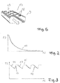
- the electrostatic charge of the wall portions 10 of the air duct 9 and Heilausströmerdüsen 6 causes a strong reduction of in The motor vehicle interior 5 finally emerging anions 8. Accordingly, the ionization module 7 would generate a correspondingly larger number of anions 8. For this, the ionization module 7 would have to be designed to be correspondingly larger (which would make it more expensive and heavier), and correspondingly more electrical energy would have to be made available for the ionization module 7.
- the decrease in the concentration of released into the motor vehicle interior 5 anions 8 is in Fig. 2 shown schematically as a Füntechnischsgraf 11. In Fig.
- the cations generated by the ionization module 7 are only "temporarily” generated in the present embodiment and are only used to generate a second ion type, which in the present case also anions 8 (albeit of a different ion type) by the 'alternately' generating different
- the statically charged wall areas 10 are discharged, so that the regeneration phase 15 not only does not reduce the concentration of the anions 8 released into the motor vehicle interior space 5 but, on the contrary, increases again after the regeneration phase 15 (which typically is 5 to 30 seconds), a normal operating mode 14 again follows, which in turn is followed by a regeneration mode 15, etc.
- This method is described in US Pat Fig. 3 shown. Again, the time is shown along the abscissa 12, whereas along the ordinate 13, the concentration of the released into the motor vehicle interior 5 anions is shown.
- An additional possible method for controlling an ionization module 7 is that the ionization module 7 is first operated in a normal operating mode 14 (see FIG Fig. 4 ). After a certain period of time (typically 1 to 3 minutes), the ionization module 7 is thereby regenerated 16 so that the ionization module 7 is simply switched off, and thus no ions (in particular no anions 8) are generated.
- this regeneration phase 16 the static charges along the wall portions 10 of the air duct 9 and the Heilausströmerdüse 6 can also reduce, for example, by the moisture usually located in the air flow L.
- the duration of the regeneration phase is typically 5 to 30 seconds.
- the metal foils 18 are formed as self-adhesive metal foils, and are, for example, adhered to the already finished air duct 9 (made of plastic for example by means of an injection molding process). Like from the Fig. 1 and 5 can be seen, the metal foils 18 are on the outer string 19 of the Beerleitkanals 9. In the present embodiment shown, the metal foils 18 are each electrically isolated from each other and moreover not grounded, In a further conceivable Ausfährungsbeispiel it is also possible that (a Part) of the Metallfollen 18 is electrically connected to each other (if necessary, via high-impedance electric conductors) and / or (optionally via a high-resistance electrical near conductor) are connected to ground potential.
- FIG. 9 Another possible embodiment for a device which effects such a locally acting field compensation is shown in FIG.
- an air duct 9 is shown in a schematic perspective view.
- ESD foils 20 On the outer sides 19 of the air duct 9 are attached over a large area, so-called ESD foils 20 attached, the ESD foils 20 are formed in the present embodiment as self-adhesive films, which are adhered to the finished air duct 9. Due to the poor electrical conductivity in relation to metal coils - in comparison to electrical insulators, however, good electrical conductivity results here also effectively a local compensation of exiting electric fields, this compensation occurring only in a relatively narrow area.
- the electrical resistance of the ESD foil 20 for the formation of mirror charges does not occur negatively over relatively short spatial distances (for example a few centimeters).
- the electrical resistance of the ESD films 20 appears to be a hindrance to the movement of electrical mirror charges, and thus a hindrance to the compensation of the electric fields.
- Another explanation for the properties of the ESD Fofie 20 is that the ESD film 20 has only a low longitudinal conductivity. This only low longitudinal conductivity allows a locally strongly varying image charge (even over short distances), and the low longitudinal conductivity makes it possible to locally sense very different surface charges.
- the individual ESO foils 20 possibly high-resistance
Landscapes
- Engineering & Computer Science (AREA)
- Mechanical Engineering (AREA)
- Physics & Mathematics (AREA)
- Thermal Sciences (AREA)
- Health & Medical Sciences (AREA)
- Life Sciences & Earth Sciences (AREA)
- Epidemiology (AREA)
- Animal Behavior & Ethology (AREA)
- General Health & Medical Sciences (AREA)
- Public Health (AREA)
- Veterinary Medicine (AREA)
- Air-Conditioning For Vehicles (AREA)
- Disinfection, Sterilisation Or Deodorisation Of Air (AREA)
Claims (17)
- Procédé conçu pour l'activation d'un dispositif d'ionisation (7) destiné à l'ionisation de l'air (L) utilisé pour la ventilation d'habitacles (5) de véhicules automobiles, où le dispositif d'ionisation (7), en mode de fonctionnement normal (14), libère temporairement des ions (8) d'un premier type d'ions (8), où le dispositif d'ionisation (7) est actionné temporairement dans au moins un mode de régénération (15, 16) au cours duquel sont libérés des ions d'un deuxième type différent du premier type d'ions (8), caractérisé en ce que le dispositif d'ionisation est actionné suivant des cycles successifs au cours desquels le dispositif d'ionisation est actionné à chaque fois pendant un certain laps de temps, d'abord en mode de fonctionnement normal (14) puis en mode de régénération.
- Procédé selon la revendication 1, caractérisé en ce que les ions du deuxième type d'ions sont libérés au moins temporairement en plus et / ou au moins temporairement en alternance avec les ions du premier type d'ions (8).
- Procédé selon l'une des revendications précédentes, caractérisé en ce qu'aucun ion (8) n'est libéré temporairement au cours d'un autre mode de régénération (16).
- Procédé selon l'une quelconque des revendications précédentes, caractérisé en ce qu'une compensation de champ effectuée localement, concernant des champs électriques créés par des charges spéculaires, se produit au moins temporairement et / ou au moins partiellement, en particulier en utilisant des mesures structurelles (18, 20) agissant passivement.
- Procédé selon l'une quelconque des revendications précédentes, caractérisé en ce que le mode de régénération (15, 16) dure plus longtemps que 2 s, 5 s, 10 s, 20 s, 30 s, 45 s et / ou 1 min et / ou dure moins longtemps que 20 s, 30 s, 45 s, 1 min, 2 min, 3 min, 4 min et / ou 5 min.
- Système de climatisation comprenant un dispositif d'ionisation (7) destiné à l'ionisation de l'air (L) utilisé pour la ventilation d'habitacles (5) de véhicules automobiles, ledit dispositif d'ionisation présentant des moyens d'ionisation (7) prévus pour la libération temporaire d'ions (8) de types d'ions différents (8), caractérisé en ce que le dispositif d'ionisation (7), en mode de fonctionnement normal (14), libère temporairement des ions (8) d'un premier type d'ions (8), où le dispositif d'ionisation (7) est actionné temporairement dans au moins un mode de régénération (15, 16) au cours duquel sont libérés des ions d'un deuxième type différent du premier type d'ions (8), où le dispositif d'ionisation est actionné suivant des cycles successifs au cours desquels le dispositif d'ionisation est actionné à chaque fois pendant un certain laps de temps, d'abord en mode de fonctionnement normal (14) puis en mode de régénération.
- Système de climatisation selon la revendication 6, caractérisé en ce que les ions du deuxième type d'ions sont libérés au moins temporairement en plus et / ou au moins temporairement en alternance avec les ions du premier type d'ions (8).
- Système de climatisation selon l'une des revendications 6 ou 7, caractérisé en ce qu'aucun ion (8) n'est libéré temporairement au cours d'un autre mode de régénération (16).
- Système de climatisation selon l'une quelconque des revendications précédentes 6 à 8, caractérisé en ce qu'une compensation de champ effectuée localement, concernant des champs électriques créés par des charges spéculaires, se produit au moins temporairement et / ou au moins partiellement, en particulier en utilisant des mesures structurelles (18, 20) agissant passivement.
- Système de climatisation selon l'une quelconque des revendications précédentes 6 à 9, caractérisé en ce que le mode de régénération (15, 16) dure plus longtemps que 2 s, 5 s, 10 s, 20 s, 30 s, 45 s et / ou 1 min et / ou dure moins longtemps que 20 s, 30 s, 45 s, 1 min, 2 min, 3 min, 4 min et / ou 5 min.
- Système de climatisation selon l'une quelconque des revendications 6 à 10, caractérisé par un dispositif de commande pour l'activation du dispositif d'ionisation (7), servant en particulier à la mise en oeuvre du mode de régénération (18, 20).
- Système de climatisation selon l'une quelconque des revendications 6 à 11, caractérisé par un premier moyen d'ionisation (7) servant à la libération au moins temporaire d'ions du premier type d'ions, et caractérisé par au moins un deuxième moyen d'ionisation servant en particulier à la libération au moins temporaire d'ions du deuxième type d'ions.
- Système de climatisation selon l'une quelconque des revendications 6 à 12, caractérisé par au moins un dispositif de guidage d'air (6, 9), en particulier un conduit de guidage d'air (9) et / ou une buse de sortie d'air (6), conduit de guidage d'air qui présente au moins partiellement un moyen de compensation de champ (18, 20) agissant localement.
- Système de climatisation selon la revendication 13, caractérisé en ce qu'au moins un moyen de compensation de champ (18, 20) agissant localement est configuré au moins partiellement comme une pluralité de parties de matière (18) électroconductrices.
- Système de climatisation selon la revendication 13 ou 14, caractérisé en ce qu'au moins un moyen de compensation de champ (18, 20) agissant localement est configuré au moins partiellement comme un composant électrique continu (20) faiblement conducteur.
- Système de climatisation selon l'une quelconque des revendications 13 à 15, caractérisé en ce qu'au moins un moyen de compensation de champ (18, 20) agissant localement, en particulier au moins une partie de matière (18) électroconductrice et / ou au moins un composant électrique (20) faiblement conducteur, est configuré de façon plate, de préférence en forme de feuille.
- Système de climatisation selon l'une quelconque des revendications 13 à 16, caractérisé en ce qu'au moins un moyen de compensation de champ (18, 20) agissant localement, en particulier au moins une partie de matière (18) électroconductrice et / ou au moins un composant électrique (20) faiblement conducteur, est réalisé en étant autoadhésif.
Applications Claiming Priority (2)
| Application Number | Priority Date | Filing Date | Title |
|---|---|---|---|
| DE102009038296A DE102009038296A1 (de) | 2009-08-21 | 2009-08-21 | Verfahren zur Ansteuerung einer Ionisierungsvorrichtung |
| PCT/EP2010/061472 WO2011020711A1 (fr) | 2009-08-21 | 2010-08-06 | Procédé de commande d'un dispositif d'ionisation |
Publications (3)
| Publication Number | Publication Date |
|---|---|
| EP2467273A1 EP2467273A1 (fr) | 2012-06-27 |
| EP2467273B1 EP2467273B1 (fr) | 2016-04-20 |
| EP2467273B2 true EP2467273B2 (fr) | 2019-03-13 |
Family
ID=42810824
Family Applications (1)
| Application Number | Title | Priority Date | Filing Date |
|---|---|---|---|
| EP10742473.1A Not-in-force EP2467273B2 (fr) | 2009-08-21 | 2010-08-06 | Procédé de controle d'un appareil d'ionisation |
Country Status (5)
| Country | Link |
|---|---|
| US (1) | US8837106B2 (fr) |
| EP (1) | EP2467273B2 (fr) |
| KR (1) | KR20120090985A (fr) |
| DE (1) | DE102009038296A1 (fr) |
| WO (1) | WO2011020711A1 (fr) |
Families Citing this family (8)
| Publication number | Priority date | Publication date | Assignee | Title |
|---|---|---|---|---|
| US10882055B2 (en) * | 2012-03-16 | 2021-01-05 | Clean Air Group, Inc. | Ionization air purification system for the passenger cabin of a vehicle |
| US20150075371A1 (en) * | 2012-03-16 | 2015-03-19 | Clean Air Group, Inc. | Ionization air purification system for the passenger cabin of a vehicle |
| CN104797444B (zh) | 2012-09-20 | 2017-04-12 | 冷王公司 | 用于运输舱中的加热、通风和空气调节单元的空气过滤系统和方法 |
| US9839756B2 (en) | 2012-11-27 | 2017-12-12 | Resmed Limited | Methods and apparatus for ionization therapy |
| EP3056364B1 (fr) * | 2015-02-11 | 2020-05-20 | CabinAir Sweden AB | Véhicule avec unité ionisante pour le nettoyage de l'air de la cabine |
| JP2018095013A (ja) * | 2016-12-09 | 2018-06-21 | トヨタ自動車株式会社 | 操縦安定用イオナイザ装置及び車両 |
| WO2022175205A1 (fr) | 2021-02-19 | 2022-08-25 | Signify Holding B.V. | Systèmes et procédés de surveillance à distance de l'ionisation de l'air |
| DE102023206792A1 (de) * | 2023-07-18 | 2025-01-23 | Karlsruher Institut für Technologie (KIT), Körperschaft des öffentlichen Rechts | Reinigungseinrichtung zur Reinigung von Luft |
Citations (4)
| Publication number | Priority date | Publication date | Assignee | Title |
|---|---|---|---|---|
| US3887846A (en) † | 1973-05-02 | 1975-06-03 | Berckheim Graf Von | Electrodes for air conditioning apparatus |
| US4542434A (en) † | 1984-02-17 | 1985-09-17 | Ion Systems, Inc. | Method and apparatus for sequenced bipolar air ionization |
| US5153811A (en) † | 1991-08-28 | 1992-10-06 | Itw, Inc. | Self-balancing ionizing circuit for static eliminators |
| US20070109711A1 (en) † | 2003-05-15 | 2007-05-17 | Sharp Kabushiki Kaisha | Ion generating element, ion generating apparatus, and electric appliance |
Family Cites Families (25)
| Publication number | Priority date | Publication date | Assignee | Title |
|---|---|---|---|---|
| DE1261295B (de) * | 1963-04-23 | 1968-02-15 | Wilhelm Peter | Geraet zur Einstellung des Ionengehaltes der in Wohnraeumen enthaltenen Luft |
| DE3331803A1 (de) * | 1983-09-02 | 1985-04-04 | Gesellschaft für Ionentechnik mbH, 7032 Sindelfingen | Vorrichtung zur erzeugung eines ueberschusses von negativen ionen in geschlossenen raeumen bzw. einem luftstrom |
| US5296019A (en) * | 1990-06-19 | 1994-03-22 | Neg-Ions (North America) Inc. | Dust precipitation from air by negative ionization |
| US5065272A (en) * | 1991-01-09 | 1991-11-12 | Elexis Corporation | Air ionizer |
| DE19651402A1 (de) | 1996-12-11 | 1998-06-18 | T E M Tech Entwicklung Und Man | Apparat zur physikalischen Aufbereitung von Luft, insbesondere von Atemluft |
| DE19919623A1 (de) | 1999-04-29 | 2000-11-02 | T E M Tech Entwicklungen Und M | Luftaufbereitungssystem zum wirksamen Abbau von luftgetragenen Gerüchen, Keimen und Schadstoffen |
| US6602330B2 (en) * | 2000-12-07 | 2003-08-05 | Mark Miller | Air purification assembly |
| JP4413445B2 (ja) | 2001-03-19 | 2010-02-10 | 三菱電機株式会社 | 空調ダクト装置 |
| US20030231459A1 (en) * | 2001-10-25 | 2003-12-18 | Robertson Reginald R. | Ion chip composite emitter |
| DE10163201A1 (de) | 2001-12-21 | 2003-07-10 | Behr Gmbh & Co | Heizungs- oder Klimaanlage insbesondere für ein Kraftfahrzeug |
| JP2004079471A (ja) | 2002-08-22 | 2004-03-11 | Denso Corp | マイナスイオン発生装置 |
| US6826030B2 (en) | 2002-09-20 | 2004-11-30 | Illinois Tool Works Inc. | Method of offset voltage control for bipolar ionization systems |
| JP4059070B2 (ja) * | 2002-12-04 | 2008-03-12 | 日産自動車株式会社 | イオン発生装置付き車両用空調装置 |
| US6985346B2 (en) | 2003-01-29 | 2006-01-10 | Credence Technologies, Inc. | Method and device for controlling ionization |
| JP4308610B2 (ja) * | 2003-09-02 | 2009-08-05 | 株式会社コガネイ | イオン発生装置 |
| GB2406222B (en) | 2003-09-22 | 2007-03-21 | Meech Static Eliminators Ltd | Electrical ioniser |
| JP3669994B2 (ja) * | 2003-09-22 | 2005-07-13 | シャープ株式会社 | 車載用空気浄化装置 |
| JP2004082123A (ja) | 2003-09-30 | 2004-03-18 | Sanyo Electric Co Ltd | 水処理装置用電極 |
| WO2007018575A2 (fr) | 2004-11-12 | 2007-02-15 | Thorrn Micro Technologies, Inc. | Production d'ions par commande temporelle du claquage dielectrique gazeux |
| JP4418778B2 (ja) | 2005-06-17 | 2010-02-24 | 清水建設株式会社 | 気体搬送用ダクトの接続構造 |
| FR2897147B1 (fr) * | 2006-02-08 | 2008-08-22 | Valeo Systemes Thermiques | Installation de ventilation, de chauffage et/ou de climatisation agencee pour la reception d'une cartouche de traitement de l'air par diffusion d'un agent traitant volatil |
| US20090001787A1 (en) * | 2007-06-26 | 2009-01-01 | Gm Global Technology Operations, Inc. | Ionized Air System and Method for Dissipating an Electrostatic Charge in a Vehicle |
| WO2009045430A1 (fr) | 2007-10-04 | 2009-04-09 | E.I.Du Pont De Nemours And Company | Canalisations d'air pour véhicules |
| US8305728B2 (en) * | 2010-06-30 | 2012-11-06 | Apple Inc. | Methods and apparatus for cooling electronic devices |
| DE102011007351A1 (de) * | 2011-04-14 | 2012-10-18 | Ford Global Technologies, Llc | Verfahren und Vorrichtung zur Verbesserung der Luft in einem Fahrzeuginnenraum |
-
2009
- 2009-08-21 DE DE102009038296A patent/DE102009038296A1/de not_active Withdrawn
-
2010
- 2010-08-06 EP EP10742473.1A patent/EP2467273B2/fr not_active Not-in-force
- 2010-08-06 WO PCT/EP2010/061472 patent/WO2011020711A1/fr not_active Ceased
- 2010-08-06 KR KR1020127007369A patent/KR20120090985A/ko not_active Withdrawn
-
2012
- 2012-02-21 US US13/401,425 patent/US8837106B2/en not_active Expired - Fee Related
Patent Citations (4)
| Publication number | Priority date | Publication date | Assignee | Title |
|---|---|---|---|---|
| US3887846A (en) † | 1973-05-02 | 1975-06-03 | Berckheim Graf Von | Electrodes for air conditioning apparatus |
| US4542434A (en) † | 1984-02-17 | 1985-09-17 | Ion Systems, Inc. | Method and apparatus for sequenced bipolar air ionization |
| US5153811A (en) † | 1991-08-28 | 1992-10-06 | Itw, Inc. | Self-balancing ionizing circuit for static eliminators |
| US20070109711A1 (en) † | 2003-05-15 | 2007-05-17 | Sharp Kabushiki Kaisha | Ion generating element, ion generating apparatus, and electric appliance |
Also Published As
| Publication number | Publication date |
|---|---|
| US20120212876A1 (en) | 2012-08-23 |
| KR20120090985A (ko) | 2012-08-17 |
| EP2467273A1 (fr) | 2012-06-27 |
| DE102009038296A1 (de) | 2011-03-31 |
| WO2011020711A1 (fr) | 2011-02-24 |
| EP2467273B1 (fr) | 2016-04-20 |
| US8837106B2 (en) | 2014-09-16 |
Similar Documents
| Publication | Publication Date | Title |
|---|---|---|
| EP2467273B2 (fr) | Procédé de controle d'un appareil d'ionisation | |
| EP2467274B1 (fr) | Conduit d'air pour appareil d'ionisation | |
| DE19859588C2 (de) | Negativionen-Erzeugungsvorrichtung | |
| EP2025351B1 (fr) | Dispositif de purification d'air doté d'un neutraliseur d'O3 et procédé de purification d'air | |
| DD257590A5 (de) | Anordnung zur erzeugung einer elektrischen koronaentladung in der luft | |
| DE102021213417A1 (de) | Lüftungseinrichtung | |
| DE102009026010A1 (de) | Elektrostatische Abscheidevorrichtung für ein Kraftfahrzeug | |
| DE3700362C2 (fr) | ||
| EP1483124B1 (fr) | Soufflerie de climatisation | |
| DE202014104576U1 (de) | Lüftungsvorrichtung zur Lüftung eines Innenraumes einer Stallung | |
| DE102014102826A1 (de) | Kraftfahrzeug | |
| EP4255610B1 (fr) | Dispositif de purification d'air, système de purification d'air et procédé de purification d`un dispositif de purification d'air et d'un système de purification d'air | |
| DE102008049278A1 (de) | Mehrzonenklimaanlage | |
| WO2006074888A1 (fr) | Procede et dispositif pour charger electrostatiquement et separer des particules difficiles a separer | |
| DE10317514B3 (de) | Klimaanlage | |
| DE102020112033A1 (de) | Hvac-system für fahrzeug | |
| DE102020121872A1 (de) | Fahrzeuginnenraum-Luftreinigungssystem | |
| DE102016004857A1 (de) | Verfahren zum Reinigen der Luft eines Fahrgastraums eines Fahrzeugs | |
| EP4408587A1 (fr) | Purificateur d'air ambiant à catalyseur d'ozone | |
| DE102008049280A1 (de) | Ionisationsvorrichtung | |
| DE19904607C1 (de) | Denaturierendes Kaskaden-Elektrofiltersystem mit mindestens zwei Filterstufen | |
| DE102022125024A1 (de) | Raumluftreiniger | |
| AT18030U1 (de) | Reinigungsvorrichtung zum Reinigen eines Gases | |
| DE102012012286B4 (de) | "lonisierungsvorrichtung zur Anreicherung eines Luftstroms mit negativ geladenen lonen" | |
| DE112020007875T5 (de) | Luftreinigungsvorrichtung mit einer UV-Lichtquelle |
Legal Events
| Date | Code | Title | Description |
|---|---|---|---|
| PUAI | Public reference made under article 153(3) epc to a published international application that has entered the european phase |
Free format text: ORIGINAL CODE: 0009012 |
|
| 17P | Request for examination filed |
Effective date: 20120321 |
|
| AK | Designated contracting states |
Kind code of ref document: A1 Designated state(s): AL AT BE BG CH CY CZ DE DK EE ES FI FR GB GR HR HU IE IS IT LI LT LU LV MC MK MT NL NO PL PT RO SE SI SK SM TR |
|
| DAX | Request for extension of the european patent (deleted) | ||
| 17Q | First examination report despatched |
Effective date: 20131030 |
|
| RAP1 | Party data changed (applicant data changed or rights of an application transferred) |
Owner name: MAHLE BEHR GMBH & CO. KG |
|
| GRAP | Despatch of communication of intention to grant a patent |
Free format text: ORIGINAL CODE: EPIDOSNIGR1 |
|
| INTG | Intention to grant announced |
Effective date: 20151120 |
|
| GRAS | Grant fee paid |
Free format text: ORIGINAL CODE: EPIDOSNIGR3 |
|
| GRAA | (expected) grant |
Free format text: ORIGINAL CODE: 0009210 |
|
| AK | Designated contracting states |
Kind code of ref document: B1 Designated state(s): AL AT BE BG CH CY CZ DE DK EE ES FI FR GB GR HR HU IE IS IT LI LT LU LV MC MK MT NL NO PL PT RO SE SI SK SM TR |
|
| REG | Reference to a national code |
Ref country code: GB Ref legal event code: FG4D Free format text: NOT ENGLISH |
|
| REG | Reference to a national code |
Ref country code: CH Ref legal event code: EP |
|
| REG | Reference to a national code |
Ref country code: AT Ref legal event code: REF Ref document number: 792005 Country of ref document: AT Kind code of ref document: T Effective date: 20160515 |
|
| REG | Reference to a national code |
Ref country code: IE Ref legal event code: FG4D Free format text: LANGUAGE OF EP DOCUMENT: GERMAN |
|
| REG | Reference to a national code |
Ref country code: DE Ref legal event code: R096 Ref document number: 502010011512 Country of ref document: DE |
|
| REG | Reference to a national code |
Ref country code: LT Ref legal event code: MG4D Ref country code: FR Ref legal event code: PLFP Year of fee payment: 7 |
|
| REG | Reference to a national code |
Ref country code: NL Ref legal event code: MP Effective date: 20160420 |
|
| PG25 | Lapsed in a contracting state [announced via postgrant information from national office to epo] |
Ref country code: NL Free format text: LAPSE BECAUSE OF FAILURE TO SUBMIT A TRANSLATION OF THE DESCRIPTION OR TO PAY THE FEE WITHIN THE PRESCRIBED TIME-LIMIT Effective date: 20160420 Ref country code: PL Free format text: LAPSE BECAUSE OF FAILURE TO SUBMIT A TRANSLATION OF THE DESCRIPTION OR TO PAY THE FEE WITHIN THE PRESCRIBED TIME-LIMIT Effective date: 20160420 Ref country code: NO Free format text: LAPSE BECAUSE OF FAILURE TO SUBMIT A TRANSLATION OF THE DESCRIPTION OR TO PAY THE FEE WITHIN THE PRESCRIBED TIME-LIMIT Effective date: 20160720 Ref country code: LT Free format text: LAPSE BECAUSE OF FAILURE TO SUBMIT A TRANSLATION OF THE DESCRIPTION OR TO PAY THE FEE WITHIN THE PRESCRIBED TIME-LIMIT Effective date: 20160420 Ref country code: FI Free format text: LAPSE BECAUSE OF FAILURE TO SUBMIT A TRANSLATION OF THE DESCRIPTION OR TO PAY THE FEE WITHIN THE PRESCRIBED TIME-LIMIT Effective date: 20160420 |
|
| PG25 | Lapsed in a contracting state [announced via postgrant information from national office to epo] |
Ref country code: HR Free format text: LAPSE BECAUSE OF FAILURE TO SUBMIT A TRANSLATION OF THE DESCRIPTION OR TO PAY THE FEE WITHIN THE PRESCRIBED TIME-LIMIT Effective date: 20160420 Ref country code: GR Free format text: LAPSE BECAUSE OF FAILURE TO SUBMIT A TRANSLATION OF THE DESCRIPTION OR TO PAY THE FEE WITHIN THE PRESCRIBED TIME-LIMIT Effective date: 20160721 Ref country code: SE Free format text: LAPSE BECAUSE OF FAILURE TO SUBMIT A TRANSLATION OF THE DESCRIPTION OR TO PAY THE FEE WITHIN THE PRESCRIBED TIME-LIMIT Effective date: 20160420 Ref country code: PT Free format text: LAPSE BECAUSE OF FAILURE TO SUBMIT A TRANSLATION OF THE DESCRIPTION OR TO PAY THE FEE WITHIN THE PRESCRIBED TIME-LIMIT Effective date: 20160822 Ref country code: ES Free format text: LAPSE BECAUSE OF FAILURE TO SUBMIT A TRANSLATION OF THE DESCRIPTION OR TO PAY THE FEE WITHIN THE PRESCRIBED TIME-LIMIT Effective date: 20160420 Ref country code: LV Free format text: LAPSE BECAUSE OF FAILURE TO SUBMIT A TRANSLATION OF THE DESCRIPTION OR TO PAY THE FEE WITHIN THE PRESCRIBED TIME-LIMIT Effective date: 20160420 |
|
| PG25 | Lapsed in a contracting state [announced via postgrant information from national office to epo] |
Ref country code: BE Free format text: LAPSE BECAUSE OF NON-PAYMENT OF DUE FEES Effective date: 20160831 Ref country code: IT Free format text: LAPSE BECAUSE OF FAILURE TO SUBMIT A TRANSLATION OF THE DESCRIPTION OR TO PAY THE FEE WITHIN THE PRESCRIBED TIME-LIMIT Effective date: 20160420 |
|
| REG | Reference to a national code |
Ref country code: DE Ref legal event code: R026 Ref document number: 502010011512 Country of ref document: DE |
|
| PLBI | Opposition filed |
Free format text: ORIGINAL CODE: 0009260 |
|
| PG25 | Lapsed in a contracting state [announced via postgrant information from national office to epo] |
Ref country code: CZ Free format text: LAPSE BECAUSE OF FAILURE TO SUBMIT A TRANSLATION OF THE DESCRIPTION OR TO PAY THE FEE WITHIN THE PRESCRIBED TIME-LIMIT Effective date: 20160420 Ref country code: RO Free format text: LAPSE BECAUSE OF FAILURE TO SUBMIT A TRANSLATION OF THE DESCRIPTION OR TO PAY THE FEE WITHIN THE PRESCRIBED TIME-LIMIT Effective date: 20160420 Ref country code: DK Free format text: LAPSE BECAUSE OF FAILURE TO SUBMIT A TRANSLATION OF THE DESCRIPTION OR TO PAY THE FEE WITHIN THE PRESCRIBED TIME-LIMIT Effective date: 20160420 Ref country code: EE Free format text: LAPSE BECAUSE OF FAILURE TO SUBMIT A TRANSLATION OF THE DESCRIPTION OR TO PAY THE FEE WITHIN THE PRESCRIBED TIME-LIMIT Effective date: 20160420 Ref country code: SK Free format text: LAPSE BECAUSE OF FAILURE TO SUBMIT A TRANSLATION OF THE DESCRIPTION OR TO PAY THE FEE WITHIN THE PRESCRIBED TIME-LIMIT Effective date: 20160420 |
|
| PLAX | Notice of opposition and request to file observation + time limit sent |
Free format text: ORIGINAL CODE: EPIDOSNOBS2 |
|
| PG25 | Lapsed in a contracting state [announced via postgrant information from national office to epo] |
Ref country code: SM Free format text: LAPSE BECAUSE OF FAILURE TO SUBMIT A TRANSLATION OF THE DESCRIPTION OR TO PAY THE FEE WITHIN THE PRESCRIBED TIME-LIMIT Effective date: 20160420 |
|
| 26 | Opposition filed |
Opponent name: VALEO SYSTEMES THERMIQUES Effective date: 20170119 |
|
| PG25 | Lapsed in a contracting state [announced via postgrant information from national office to epo] |
Ref country code: MC Free format text: LAPSE BECAUSE OF FAILURE TO SUBMIT A TRANSLATION OF THE DESCRIPTION OR TO PAY THE FEE WITHIN THE PRESCRIBED TIME-LIMIT Effective date: 20160420 |
|
| REG | Reference to a national code |
Ref country code: CH Ref legal event code: PL |
|
| GBPC | Gb: european patent ceased through non-payment of renewal fee |
Effective date: 20160806 |
|
| PG25 | Lapsed in a contracting state [announced via postgrant information from national office to epo] |
Ref country code: CH Free format text: LAPSE BECAUSE OF NON-PAYMENT OF DUE FEES Effective date: 20160831 Ref country code: LI Free format text: LAPSE BECAUSE OF NON-PAYMENT OF DUE FEES Effective date: 20160831 |
|
| PG25 | Lapsed in a contracting state [announced via postgrant information from national office to epo] |
Ref country code: SI Free format text: LAPSE BECAUSE OF FAILURE TO SUBMIT A TRANSLATION OF THE DESCRIPTION OR TO PAY THE FEE WITHIN THE PRESCRIBED TIME-LIMIT Effective date: 20160420 |
|
| REG | Reference to a national code |
Ref country code: IE Ref legal event code: MM4A |
|
| PLBB | Reply of patent proprietor to notice(s) of opposition received |
Free format text: ORIGINAL CODE: EPIDOSNOBS3 |
|
| PG25 | Lapsed in a contracting state [announced via postgrant information from national office to epo] |
Ref country code: GB Free format text: LAPSE BECAUSE OF NON-PAYMENT OF DUE FEES Effective date: 20160806 Ref country code: IE Free format text: LAPSE BECAUSE OF NON-PAYMENT OF DUE FEES Effective date: 20160806 |
|
| REG | Reference to a national code |
Ref country code: FR Ref legal event code: PLFP Year of fee payment: 8 |
|
| PG25 | Lapsed in a contracting state [announced via postgrant information from national office to epo] |
Ref country code: LU Free format text: LAPSE BECAUSE OF NON-PAYMENT OF DUE FEES Effective date: 20160806 |
|
| REG | Reference to a national code |
Ref country code: AT Ref legal event code: MM01 Ref document number: 792005 Country of ref document: AT Kind code of ref document: T Effective date: 20160806 |
|
| PG25 | Lapsed in a contracting state [announced via postgrant information from national office to epo] |
Ref country code: AT Free format text: LAPSE BECAUSE OF NON-PAYMENT OF DUE FEES Effective date: 20160806 |
|
| PG25 | Lapsed in a contracting state [announced via postgrant information from national office to epo] |
Ref country code: CY Free format text: LAPSE BECAUSE OF FAILURE TO SUBMIT A TRANSLATION OF THE DESCRIPTION OR TO PAY THE FEE WITHIN THE PRESCRIBED TIME-LIMIT Effective date: 20160420 Ref country code: HU Free format text: LAPSE BECAUSE OF FAILURE TO SUBMIT A TRANSLATION OF THE DESCRIPTION OR TO PAY THE FEE WITHIN THE PRESCRIBED TIME-LIMIT; INVALID AB INITIO Effective date: 20100806 |
|
| PG25 | Lapsed in a contracting state [announced via postgrant information from national office to epo] |
Ref country code: TR Free format text: LAPSE BECAUSE OF FAILURE TO SUBMIT A TRANSLATION OF THE DESCRIPTION OR TO PAY THE FEE WITHIN THE PRESCRIBED TIME-LIMIT Effective date: 20160420 Ref country code: MT Free format text: LAPSE BECAUSE OF FAILURE TO SUBMIT A TRANSLATION OF THE DESCRIPTION OR TO PAY THE FEE WITHIN THE PRESCRIBED TIME-LIMIT Effective date: 20160420 Ref country code: IS Free format text: LAPSE BECAUSE OF FAILURE TO SUBMIT A TRANSLATION OF THE DESCRIPTION OR TO PAY THE FEE WITHIN THE PRESCRIBED TIME-LIMIT Effective date: 20160420 Ref country code: MK Free format text: LAPSE BECAUSE OF FAILURE TO SUBMIT A TRANSLATION OF THE DESCRIPTION OR TO PAY THE FEE WITHIN THE PRESCRIBED TIME-LIMIT Effective date: 20160420 |
|
| PG25 | Lapsed in a contracting state [announced via postgrant information from national office to epo] |
Ref country code: BG Free format text: LAPSE BECAUSE OF FAILURE TO SUBMIT A TRANSLATION OF THE DESCRIPTION OR TO PAY THE FEE WITHIN THE PRESCRIBED TIME-LIMIT Effective date: 20160420 |
|
| REG | Reference to a national code |
Ref country code: FR Ref legal event code: PLFP Year of fee payment: 9 |
|
| APAH | Appeal reference modified |
Free format text: ORIGINAL CODE: EPIDOSCREFNO |
|
| APBM | Appeal reference recorded |
Free format text: ORIGINAL CODE: EPIDOSNREFNO |
|
| APBP | Date of receipt of notice of appeal recorded |
Free format text: ORIGINAL CODE: EPIDOSNNOA2O |
|
| PG25 | Lapsed in a contracting state [announced via postgrant information from national office to epo] |
Ref country code: AL Free format text: LAPSE BECAUSE OF FAILURE TO SUBMIT A TRANSLATION OF THE DESCRIPTION OR TO PAY THE FEE WITHIN THE PRESCRIBED TIME-LIMIT Effective date: 20160420 |
|
| PGFP | Annual fee paid to national office [announced via postgrant information from national office to epo] |
Ref country code: FR Payment date: 20180823 Year of fee payment: 9 Ref country code: DE Payment date: 20180831 Year of fee payment: 9 |
|
| APBU | Appeal procedure closed |
Free format text: ORIGINAL CODE: EPIDOSNNOA9O |
|
| PUAH | Patent maintained in amended form |
Free format text: ORIGINAL CODE: 0009272 |
|
| STAA | Information on the status of an ep patent application or granted ep patent |
Free format text: STATUS: PATENT MAINTAINED AS AMENDED |
|
| 27A | Patent maintained in amended form |
Effective date: 20190313 |
|
| AK | Designated contracting states |
Kind code of ref document: B2 Designated state(s): AL AT BE BG CH CY CZ DE DK EE ES FI FR GB GR HR HU IE IS IT LI LT LU LV MC MK MT NL NO PL PT RO SE SI SK SM TR |
|
| REG | Reference to a national code |
Ref country code: DE Ref legal event code: R102 Ref document number: 502010011512 Country of ref document: DE |
|
| REG | Reference to a national code |
Ref country code: DE Ref legal event code: R119 Ref document number: 502010011512 Country of ref document: DE |
|
| PG25 | Lapsed in a contracting state [announced via postgrant information from national office to epo] |
Ref country code: FR Free format text: LAPSE BECAUSE OF NON-PAYMENT OF DUE FEES Effective date: 20190831 Ref country code: DE Free format text: LAPSE BECAUSE OF NON-PAYMENT OF DUE FEES Effective date: 20200303 |