EP2467274B1 - Air duct for ionisation device - Google Patents
Air duct for ionisation device Download PDFInfo
- Publication number
- EP2467274B1 EP2467274B1 EP10742476.4A EP10742476A EP2467274B1 EP 2467274 B1 EP2467274 B1 EP 2467274B1 EP 10742476 A EP10742476 A EP 10742476A EP 2467274 B1 EP2467274 B1 EP 2467274B1
- Authority
- EP
- European Patent Office
- Prior art keywords
- air
- ions
- air conduction
- conduction device
- ionisation
- Prior art date
- Legal status (The legal status is an assumption and is not a legal conclusion. Google has not performed a legal analysis and makes no representation as to the accuracy of the status listed.)
- Not-in-force
Links
Images
Classifications
-
- B—PERFORMING OPERATIONS; TRANSPORTING
- B60—VEHICLES IN GENERAL
- B60H—ARRANGEMENTS OF HEATING, COOLING, VENTILATING OR OTHER AIR-TREATING DEVICES SPECIALLY ADAPTED FOR PASSENGER OR GOODS SPACES OF VEHICLES
- B60H1/00—Heating, cooling or ventilating [HVAC] devices
- B60H1/00507—Details, e.g. mounting arrangements, desaeration devices
- B60H1/00557—Details of ducts or cables
- B60H1/00564—Details of ducts or cables of air ducts
-
- B—PERFORMING OPERATIONS; TRANSPORTING
- B60—VEHICLES IN GENERAL
- B60H—ARRANGEMENTS OF HEATING, COOLING, VENTILATING OR OTHER AIR-TREATING DEVICES SPECIALLY ADAPTED FOR PASSENGER OR GOODS SPACES OF VEHICLES
- B60H3/00—Other air-treating devices
-
- A—HUMAN NECESSITIES
- A61—MEDICAL OR VETERINARY SCIENCE; HYGIENE
- A61L—METHODS OR APPARATUS FOR STERILISING MATERIALS OR OBJECTS IN GENERAL; DISINFECTION, STERILISATION OR DEODORISATION OF AIR; CHEMICAL ASPECTS OF BANDAGES, DRESSINGS, ABSORBENT PADS OR SURGICAL ARTICLES; MATERIALS FOR BANDAGES, DRESSINGS, ABSORBENT PADS OR SURGICAL ARTICLES
- A61L9/00—Disinfection, sterilisation or deodorisation of air
- A61L9/16—Disinfection, sterilisation or deodorisation of air using physical phenomena
- A61L9/22—Ionisation
-
- B—PERFORMING OPERATIONS; TRANSPORTING
- B60—VEHICLES IN GENERAL
- B60H—ARRANGEMENTS OF HEATING, COOLING, VENTILATING OR OTHER AIR-TREATING DEVICES SPECIALLY ADAPTED FOR PASSENGER OR GOODS SPACES OF VEHICLES
- B60H1/00—Heating, cooling or ventilating [HVAC] devices
-
- B—PERFORMING OPERATIONS; TRANSPORTING
- B60—VEHICLES IN GENERAL
- B60H—ARRANGEMENTS OF HEATING, COOLING, VENTILATING OR OTHER AIR-TREATING DEVICES SPECIALLY ADAPTED FOR PASSENGER OR GOODS SPACES OF VEHICLES
- B60H3/00—Other air-treating devices
- B60H3/0071—Electrically conditioning the air, e.g. by ionizing
Definitions
- the invention relates to an air-handling device, in particular an air-guiding channel and / or an air-outlet nozzle, preferably an air-guiding device for an ionization device.
- the invention further relates to an Ionteleitersvortechnisch and an air conditioner, in particular a Kraft mecanickilmastrom.
- filters that clean the vehicle interior to be supplied fresh air and / or used to remove unwanted odors (especially outside air odors).
- ionization devices have also been installed in motor vehicles as part of the Erat equipment.
- the ionization devices should provide air freshening, ie, a feeling that there is "fresh air”.
- ionization devices are used to kill pathogens (especially bacteria and / or viruses), which, if appropriate, are located in the fresh air and / or recirculating air to be supplied to the vehicle interior.
- pathogens especially bacteria and / or viruses
- a combination of a positively charged electrode and a negatively charged electrode is usually used.
- the effective ion is often HO 2 - .
- the ionizers In order for the ionizers to be effective, it is not only necessary for them to generate ions, but also for the ions generated by the ionizers over an extended period of time remain available and are usually released in the ventilated interior. This is a problem particularly in the automotive field, where the conditioned air is directed over a larger number of spoilers, spoilers and exhaust nozzles before the conditioned air is discharged into the vehicle interior. Experiments have shown that an initially sufficiently high ion concentration can be reduced by more than a factor of 10 within a few minutes. This reduces the effectiveness of air ionization and requires appropriate countermeasures.
- JP 20063492989 A it is proposed to provide a flexible air duct of an air conditioner having an ionization device with a continuous, electrically conductive coating.
- the electrically conductive coating is grounded.
- it is intended to prevent the ions flowing through the tube from being electrically neutralized and thus lost.
- JP 2004-79471 A will describe a method with the loss of already generated anions in its subsequent to the ionization device. Air duct, to be prevented. For this purpose, it is proposed that the ionization device is switched off after a continuous operation over a period of 10 to 40 minutes for about 3 to 7 minutes.
- WO 2009/045438 A1 For example, various organic polymer compositions provided with a metallic coating have been proposed for use as air ducts in automobiles.
- the document JP 2002277010 relates to an air conditioner with a Ionengenerstor and air ducts with the features of the preamble of claim 1.
- a channel of the air conditioner has a fan for sucking in atmospheric air and forwarding the air into an air duct, a filter for removing dust from the air and a negative ion generating ion generator.
- the document JP 2004079471 relates to an air conditioner with an ion generator that can emit negative ions.
- the document JP 2004182123 discloses an air conditioning system for a motor vehicle having an ion generating device by means of which ions can be generated.
- the ion generating device is disposed in an air duct of the air conditioner.
- the ion generator may generate positive and negative ions in a clean mode. In a refresh mode negative ions can be generated.
- the refresh mode may be downstream of the clean mode.
- an air-guiding device in particular an air-guiding duct and / or an air-venting nozzle, preferably an air-guiding device for an ionizing device (here in particular an air-guiding duct and / or an air-venting jet for an ionizing device) according to claim 1.
- Ionization devices are known in different designs.
- ionization devices may include a suitably configured electrode to which a negative high voltage is applied. The electrodes then release negatively charged ions, so-called anions. Negative ion-containing air is usually perceived as "fresh air”. Accordingly, one usually speaks of a so-called “relax mode” (Relax for relaxation).
- an ionization device also has a suitably shaped electrode to which a positive high voltage is applied. The thus positively charged maximum voltage electrode emits accordingly positively charged ions, so-called cations.
- the generated cations can combine with other molecules and / or ions (for example with O 2 - ions to HO 2 - ions), which in turn can be purifying (eg bactericidal). Therefore This is usually referred to here as a "clean" operating mode (clean for clean).
- a "clean" operating mode cleaning for clean.
- several electrodes both with the same high voltage supply, as well as with different high voltage power supply
- ionization devices are operated in such a way that exclusively or at least predominantly ions of a certain type of ion - for example anions, such as in particular O 2 - ions and / or HO 2 - ions are generated (even if the ionization device has differently designed electrodes ).
- At least one local field compensation means it is possible, in particular, to enable local field compensation of electric fields with the aid of mirror charges, at least temporarily and / or at least in regions. It is particularly advantageous if the or the locally acting field compensation means are designed as passive acting locally acting field compensation means, so that, for example, no complex control electronics is required and / or energy for operation of the field compensating means (or the optionally present multiple field compensation means) must be provided.
- the inventors have discovered to their own surprise that not particularly well conductive, surface applied materials and / or particularly good insulating surfaces causes a particularly high concentration of final liberated ions (for example in a motor vehicle interior inside).
- the magnitude of local structures is typically in a range of a few centimeters (or square centimeters), for example, with typical lengths and / or widths of 0.5 cm, 1 cm, 1.5 cm, 2 cm, 3 cm, 4 cm or 5 cm.
- At least one locally acting field compensating means is formed at least in regions as a plurality of electrically conductive material sections.
- Such a locally acting field compensating agent has only a slight tendency to destroy ions while at the same time being of a relatively simple and inexpensive construction.
- the size dimensions for the proposed design of the electrically conductive material sections is usually in a range of up to 0.5 cm, 1 cm, 1.5 cm, 2 cm, 3 cm, 4 cm or 5 cm.
- the electrical conductivity of at least one electrically conductive material section is greater than or equal to 10 4 S / m, 10 5 S / m and / or 10 6 S / m (S for Siemens and m for meter). Such electrical conductivities have been proven to be able to realize a particularly good, local field compensation.
- the electrical decoupling may be effected by a material interruption of the electrically conductive material, in particular when the carrier material (for example the material of the air guiding device) has a relatively low conductivity.
- the electrical decoupling of the at least two locally acting field compensating means at least partially has a conductivity of less than or equal to 10 5 S / m, 10 4 S / m, 10 3 S / m, 10 2 S / m, 10 1 S / m and / or 10 0 S / m.
- the said, relatively low electrical conductivities have proven to be particularly suitable for the presently proposed air guiding device.
- ESD films or the like components are used (ESD for Electro Static Device).
- ESD Electro Static Device
- the assembly of the corresponding components can be easily stowed, since they can be attached as a single, large areas. This can simplify the production of the air guide device again.
- the air duct thus treated or equipped with the electrically slightly conductive component can be connected by a conductive connection to a ground potential, in order to be able to dissipate an arising charge optionally.
- At least one electrically slightly conductive component at least partially has an electrical conductivity of less than or equal to 10 5 S / m, 10 4 S / m, 10 3 S / m, 10 2 S / m, 10 1 S / m, 10 0 S / m, 10 -1 S / m, 10 -2 S / m, 10 -3 S / m, 10 -4 S / m or 10 -5 S / m
- the use of materials with the mentioned conductivities has proved to be particularly suitable in first attempts.
- the locally acting field compensating means in particular at least one electrically conductive material section and / or at least one electrically slightly conducting component, is designed to be flat and film-like.
- Initial tests have shown that the local acting field compensating means as a rule does not (or only to a minor extent) depend on their depth (in particular their component dimensions in a direction perpendicular to the direction of air flow). With a flat or film-like structure, therefore, a highly effective device can be formed with low material consumption (and thus low weight and / or low cost).
- Typical thicknesses of flat components and / or films are in the range of 0.1 mm.
- a further particularly preferred embodiment of the air guiding device results, moreover, if at least one locally acting field compensating means, in particular at least one electrically conductive material section and / or at least one electrically slightly conductive component is designed to be self-adhesive.
- a particularly simple assembly of the locally acting field compensation means on the air guide device (such as on an air duct, on a Lucasausströmerdüse, possibly also to other modules) can be realized.
- metal foils and / or ESD films are already commercially available in large quantities at present in self-adhesive form. This allows a further cost reduction can be achieved and a rapid implementation of the presently proposed air duct device can be done very quickly.
- an ionization device which has at least one ionizing agent for the at least temporary release of ions of a first ion type, and at least one air guiding device with the structure described above.
- An ionization device embodied in this way can make it possible for a particularly high proportion of the ions generated by the ionization device to arrive at the actual "target" (ie in particular to be released into a motor vehicle interior).
- the overall ionization device can be constructed particularly simply, inexpensively and effectively.
- a certain ion concentration at the actual air outlet can also be achieved if a low ion concentration in relation to known ionization devices is generated at the location of the ionization agent.
- the ionizing agent can be made smaller, less powerful, lighter and less energy-consuming, in particular.
- the effectiveness of the presently proposed ionization device can be significantly increased again if it is designed and set up so that it can be operated at least temporarily in at least one regeneration mode.
- the regeneration phases can be consciously accepted that over a certain (as far as possible) period of time the (actually) desired concentration mixture and / or the concentration of the ions released into the motor vehicle interior changes. It is even conceivable that for a short time the number of released ions (at least for some ion types) is reduced to zero. Nevertheless, despite (or thanks to) the insertion of such regeneration phases, it is possible to increase the amount of ions released in the time average or to make the concentration ratio of the ions released into the motor vehicle interior very close to the desired target value.
- the regeneration phase acts less on the actual ionizing agent than on the components left behind by the ionizing agent in the air stream (ie in particular on air flow devices downstream of the air stream, such as air ducts and / or air outlet nozzles).
- the ionization device can be operated in particular such that in at least one regeneration mode at least temporarily ions of a second type of ion different from the first ion type are released and / or at least temporarily no ions, in particular no ions of the first ion type were released.
- a different sign of the charge can be provided.
- the ions of the first ion type are anions
- the ions of the second ion type may accordingly be cations (which, if appropriate, could also temporarily transpose only in the form of an "intermediate").
- the ions may also have a have different charge (for example, single, double, triple, etc. elementary charge).
- the ions of opposite charge may additionally or alternatively also be different molecules that have been ionized or ionized (such as the ions O 2 - and HO 2 - ) already described above.
- the possibly already electrostatically charged regions of the actual ionization means downstream components can be discharged by the placement of opposite charge carriers. It is also possible, as it were, to produce an opposite pre-charge distribution so that, in a first operating phase of the ionization device downstream of the regeneration phase, the components downstream of the actual ionization agent are first discharged and only then recharged by the ions of the first ion type.
- the duration of the regeneration phase may typically be in a range between 5 and 30 seconds, while the "normal" operating time is in an interval between 30 seconds and 3 minutes.
- the ions of the second ion type can be released at least temporarily additionally and / or at least temporarily as an alternative to the ions of the first ion type. It is thus possible that (at least temporarily) during the regeneration phase predominantly or (essentially) exclusively ions of the second ion type are released. In this case, the duration of the regeneration phase can typically be kept particularly short. However, it is also possible for the ions of the second ion type to be released while the generation of ions of the first ion type is continued substantially continuously.
- At least temporarily no ions in particular at least temporarily no ions of the first ion type are released.
- This can be realized for example by a complete Ausschaben the ionization device.
- regeneration of the overall arrangement can take place after relatively short periods of time. Typically, turn-off times are in the range of 5 to 30 seconds (typical turn-on times in normal operating mode typically 30 seconds to 3 minutes). This solution is particularly advantageous because it can be realized structurally particularly simple.
- this method can be used for ionization devices having only a single high voltage source and / or a single high voltage electrode.
- a particularly fast regeneration can be realized in particular if relatively moist air is present, since this promotes a rapid discharge of electrostatic accumulations.
- the control of the ionization device can be done by at least one control device for controlling the ionization device.
- a control device for example, a single board. Computer or the like. It is possible that a special control device for controlling the regeneration mode is provided.
- the functionality is taken over by an electronic control, which is typically present anyway in motor vehicles (for example an electronic control system for a motor vehicle air conditioning system). Since the computational load for a control device is typically relatively small, this additional workload is usually not a problem.
- an air conditioning system in particular an automotive air conditioning system which at least one air guide device with the structure described above and / or at least one ionization device having the structure described above.
- the air conditioning system then has the properties and advantages already mentioned in connection with the previously described air-guiding device and / or with the ionization device described above in an analogous manner.
- the motor vehicle for which the motor vehicle air conditioning system is intended may be, in any desired manner, a watercraft, an aircraft and / or a land vehicle (rail-bound / non-sill-bound).
- FIG. 1 an automotive air conditioning system is shown in a schematic cross-sectional view.
- the motor vehicle kiln system 1 is shown in a greatly simplifying view, which essentially concentrates on the areas which are related to the air treatment by ionization of the air flow L to be processed by the motor vehicle air conditioning system 1.
- the sucked by the motor vehicle air conditioner 1 by means of a blower 2 air L is first passed through a filter 3, in the pollen, dirt particles and the like which may be contained in the ambient air, have been filtered out. Subsequently, the air flow L is passed through a radiator 4 and tempered accordingly (of course, the temperature can also be done by a mixture of hot and cold air, moreover, the air can also be cooled by means of an evaporator, etc.).
- the already largely conditioned air flow L is, before it is released via a Lucasausströmerdüse 6 in a Kraftfährzeuginnenraum 5, first passed through an ionization module 7.
- anions 8 are generated, which are perceived by the vehicle occupants as "fresh air".
- the anions 8 generated by the ionization module 7 must first be passed through correspondingly shaped air guide channels 9 and flow through the air outlet nozzle 6. In this case, some of the anions 8 generated by the ionization module 7 strike the walls of the air duct 9 or the air vent nozzle 6 and deliver their charge to the corresponding edge region 10. Over time, this leads to an electrostatic charge of certain wall regions 10 of the air guide element 9 and the air outlet nozzle 6. However, the electrostatic charge of the corresponding wall regions 10 is not uniform, so that electric fields occur between wall regions 10 charged to different degrees. The electric fields again affect the air flow L (In particular, the ions contained in the air flow L), in particular the trajectory of the anions 8, so that the system behaves extremely dynamic and difficult to predict.
- the ionization module 7 would have to generate a correspondingly larger number of anions 8.
- the ionization module 7 would have to be designed to be correspondingly larger (which would make it more expensive and heavier), and correspondingly more electrical energy would have to be made available for the ionization module 7.
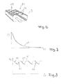
- the decrease in the concentration of released into the motor vehicle interior 5 anions 8 is in Fig. 2 shown schematically as a function graph 11 (unless separate measures, such as special operating procedures and / or constructive measures are taken). In Fig.
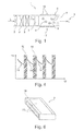
- Fig. 1 indicated arrangement of a grid 17 of spaced metal foils 18.
- Possible details of the position and arrangement of the metal foils 18 on the air duct 9 are also in Fig. 5 to recognize.
- a regular grid of similarly shaped metal foils 18 is used.
- the individual “columns" of the grid are in each case offset relative to one another, so that the metal foils 18 are to some extent arranged "against each other" in a gap.
- the metal foils 18 are formed as self-adhesive metal foils, and are glued, for example, on the already finished air duct 9 (which was made of plastic for example by means of an injection molding process).
- the metal foils 18 are on the outside 19 of the air duct 9.
- the metal foils 18 are each disposed electrically isolated from each other and also not grounded. In a further conceivable embodiment, it is also possible for the (or a part of) the metal foils 18 to be electrically connected to one another (possibly upper high-resistance electrical conductors) and / or (optionally via a high-resistance electrical conductor) to earth potential.
- the localized mobility of charge carriers in the individual metal foils 18 causes mirror charges to form in the metal foils 18 over a limited distance, leading to electric landings or charge clusters at the inner wall regions 10 and 10 / or in the interior of the air duct 9 can correspond.
- the mirror charges formed thereby cause a reduction or advantageous redistribution of the existing electric fields, which ultimately leads to a higher proportion through the air duct 9 passing through anions 8 can lead (without these going to the wall portions 10 of the air duct 9 and the Heilausströmerelements 6 lost). Thereby, the exit of anions 8 in the motor vehicle interior 5 can be improved.
- FIG. 6 Another possible embodiment for a device that effects such a locally acting field compensation is in Fig. 6 presented.
- an air duct 9 is shown in a schematic perspective view.
- ESD foils 20 are provided on the outer sides 19 of the air duct 9 are mounted over a large area.
- the ESD foils 20 are formed in the present embodiment illustrated as self-adhesive films, which are adhered to the finished air duct 9. Due to the poor electrical conductivity in relation to metal foils - in relation to electrical insulators, however, good electrical conductivity - here also effectively results in a local compensation occurring electric fields, which compensation occurs only in a relatively narrow area.
- the ESD filler 20 has only a low longitudinal conductivity. This low longitudinal conductivity allows a locally greatly varying image charge (even over short distances), or makes the only small L jossleitfählgkeit it possible that locally very different surface charges can be dissipated. Also in the presently illustrated embodiment of Fig. 6 is it possible that the individual ESD foils 20 (possibly high-resistance) are electrically connected to one another and / or (if appropriate via high-resistance connecting lines) connected to ground.
- the ionization module 7 in order to increase the concentration of anions 8 released in the motor vehicle interior 5 on an average time basis, it is possible to operate the ionization module 7 only in a normal operating mode 14 over a certain period of time (typically 1 to 3 minutes) (compare with FIG Fig. 3 ). After a certain period of time, the motor vehicle air conditioning system 1 is switched to a regeneration mode 15 in which not only anions 8 (as in FIG Fig. 1 shown) are generated, but in addition also cations of the ionization module 7 (which must be designed accordingly for this purpose) are generated.
- a regeneration mode 15 in which not only anions 8 (as in FIG Fig. 1 shown) are generated, but in addition also cations of the ionization module 7 (which must be designed accordingly for this purpose) are generated.
- the cations generated by the ionization module 7 are only “temporarily” generated in the present embodiment and are only used to generate a second type of ion, which in the present case are also anions 8 (although of a different ion type).
- the "alternately” generation of different types of ions leads to a discharge of the statically charged wall regions 10, so that thanks to the regeneration phase 15, the concentration of the in the motor vehicle interior Not only does it not decrease further, but on the contrary, it can increase again.
- a normal operating mode 14 again follows, which in turn is followed by a regeneration mode 15, etc. This procedure is in Fig. 3 shown. Again, the time is shown along the abscissa 12, whereas along the ordinate 13, the concentration of the released into the motor vehicle interior 5 anions is shown.
- a second possible method for controlling an ionization module 7 is then that the ionization module 7 - analogously to the previous embodiment - is first operated in a normal operating mode 14 (see Fig. 4 ). After a certain period of time (typically 1 to 3 minutes), the ionization module 7 is regenerated 16 in that the ionization module 7 is simply switched off, and thus no ions (in particular no anions 8) are generated. In this regeneration phase 16, the static charges along the wall portions 10 of the air duct 9 and the Lucasausströmerdüse 6 can also degrade, for example, by the usually located in the air flow L moisture. The duration of the regeneration phase is typically 5 to 30 seconds.
Description
Die Erfindung betrifft eine Luftfühtungsvorrichtung, insbesondere einen Luftführungskanal und/oder eine Luftaustassdüse, bevorzugt eine Luftführungsvorrichtung für eine Ionisierungsvorrichtung. Die Erfindung betrifft weiterhin eine Ionteierungsvorrichtung sowie eine Klimaanlage, insbesondere eine Kraftfahrzeugkilmaanlage.The invention relates to an air-handling device, in particular an air-guiding channel and / or an air-outlet nozzle, preferably an air-guiding device for an ionization device. The invention further relates to an Ionteierungsvorrichtung and an air conditioner, in particular a Kraftfahrzeugkilmaanlage.
Um die im Zusammenhang mit der Belüftung von Kraftfahrzeugen über die Jahre hinweg gestiegenen Komfortanforderungen der Fahrzeugkunden zu befriedigen, hat die Funktionsvielfalt und die Komplexität von Kraftfahrzeugklimaanlagen entsprechend zugenommen.In order to meet the increased comfort requirements of vehicle customers in connection with the ventilation of motor vehicles over the years, the functional diversity and the complexity of motor vehicle air conditioning systems has increased accordingly.
So haben sich Klimaanlagen zwischenzeitlich in sämtlichen Fahrzeugklassen durchgesetzt. Mit derartigen Fahrzeugkilmaanlagen kann die dem Fahrzeuginnenraum zuzuführende Frischluft erwärmt werden. Heutzutage ist jedoch meist auch eine Kühlfunkflon vorgesehen, mit der die dem Fahrzeuginnenraum zuzuführende Frischluft auch abgekühlt werden kann.Thus, air conditioners have prevailed meanwhile in all vehicle classes. With such Fahrzeugkilmaanlagen the vehicle interior to be supplied fresh air can be heated. Nowadays, however usually also a Kühlfunkflon provided with which the vehicle interior to be supplied fresh air can also be cooled.
Weitere Funktionen, die zwischenzeitlich in zunehmendem Umfang bei der Belüftung von Kraftfahrzeugen realisiert werden, sind beispielsweise Filter, die die dem Fahrzeuginnenraum zuzuführende Frischluft reinigen und/oder zur Entfernung von unerwünschten Gerüchen (insbesondere Außenluftgerüchen) eingesetzt werden.Other functions, which are realized in the meantime increasingly in the ventilation of motor vehicles, for example, filters that clean the vehicle interior to be supplied fresh air and / or used to remove unwanted odors (especially outside air odors).
Seit einiger Zeit werden in Kraftfahrzeugen auch im Rahmen der Eratausrüstung Ionisierungsgeräte verbaut. Die Ionisierungsgeräte sollen einerseits für eine Luftauffrischung sorgen, also für ein Empfinden, dass eine "frische Luft" vorliegt. Andererseits werden Ionisierungsgeräte dazu verwendet, um Krankheitserreger (insbesondere Bakterien und/oder Viren), welche sich gegebennenfalls in der dem Fahrzeuginnenraum zuzuführenden Frischluft und/oder Umluft befinden, abzutöten. Um Krankheitserreger abzutöten wird meist eine Kombination aus einer positiv geladenen Elektrode sowie einer negativ geladenen Elektrode verwendet. Als wirksames Ion dient dabei häufig HO2 -. Um HO2 - zu erzeugen wird aus Wasser (H2O), welches In Form von Luftfeuchtigkeit vorliegt mit Hilfe einer positiv geladenen Elektrode H+ erzeugt, weiches anschließend an der negativ geladenen Elektrode zu H reduziert wird. H kombiniert anschließend mit O2 - zum wirksamen HO2 -.For some time, ionization devices have also been installed in motor vehicles as part of the Erat equipment. On the one hand, the ionization devices should provide air freshening, ie, a feeling that there is "fresh air". On the other hand, ionization devices are used to kill pathogens (especially bacteria and / or viruses), which, if appropriate, are located in the fresh air and / or recirculating air to be supplied to the vehicle interior. In order to kill pathogens, a combination of a positively charged electrode and a negatively charged electrode is usually used. The effective ion is often HO 2 - . In order to generate HO 2 - , water (H 2 O), which is present in the form of atmospheric moisture, generates H + by means of a positively charged electrode, which is then reduced to H at the negatively charged electrode. H then combines with O 2 - to the effective HO 2 - .
Zur Lufterfrischurg werden dagegen meist negativ geladenen (einfache) Hochspannungselektroden verwendet, welche zum Beispiel in der zuzuführenden Luft enthaltene Sauerstoffmoleküle (O2) zu negativ geladenen Sauerstoffionen reduzieren (O2 -).For air freshening, by contrast, mostly negatively charged (simple) high-voltage electrodes are used which, for example, reduce oxygen molecules (O 2 ) contained in the air to be supplied to negatively charged oxygen ions (O 2 - ).
Damit die Ionisierungsgeräte ihre Wirksamkeit entfalten können, ist es nicht nur erforderlich, dass diese Ionen erzeugen, sondern dass die von den Ionisierungsgeräten erzeugten Ionen auch über eine längere Zeitdauer hinweg vorhanden bleiben und in aller Regel auch in den zu belüftenden Innenraum freigesetzt werden. Dies ist insbesondere im Kraftfahrzeugbereich ein Problem, wo die aufbereitete Luft über eine größere Anzahl von Luftleitelementen, Luftleitklappen und Auslaßdüsen gelenkt wird, bevor die aufbereitete Luft in den Kraftfahrzeuginnenraum abgegeben wird. Versuche haben ergeben, dass sich eine anfänglich ausreichend hohe Ionenkonzentration innerhalb von wenigen Minuten um mehr als den Faktor 10 verringern kann. Dies verringert die Wirksamkeit der Luftionisierung und macht entsprechenden Gegenmaßnahmen erforderlich.In order for the ionizers to be effective, it is not only necessary for them to generate ions, but also for the ions generated by the ionizers over an extended period of time remain available and are usually released in the ventilated interior. This is a problem particularly in the automotive field, where the conditioned air is directed over a larger number of spoilers, spoilers and exhaust nozzles before the conditioned air is discharged into the vehicle interior. Experiments have shown that an initially sufficiently high ion concentration can be reduced by more than a factor of 10 within a few minutes. This reduces the effectiveness of air ionization and requires appropriate countermeasures.
In
In
Das Dokument
Das Dokument
Das Dokument
Das Dokument
Obwohl die bereits vorgeschlagenen Maßnahmen grundsätzlich geeignet sind, das beschriebene Problem des verlusts von bereits erzeugten Ionen zu verringern, weisen die bereits vorgeschlagenen Verfahren und Vorrichtungen jedoch nach wie vor unterschiedlichste Probleme auf, wie beispielsweise hohe Kosten, nicht ausreichende Wirksamkeit und übermäßige elektrische Neutralisierung bereits erzeugter Ionen.Although the measures already proposed are fundamentally suitable for reducing the described problem of loss of already generated ions, the methods and devices already proposed still present various problems, such as high costs, insufficient effectiveness and excessive electrical neutralization of already generated ones ions.
Es ist daher die Aufgabe der Erfindung eine Luftführungsvorrichtung vorzuschlagen, die besonders geeignet als Luftführungsvorrichtung für eine Ionisierungsvorrichtung ist und Vorzüge gegenüber bekannten Luftführungsvorrichtungen aufweiset. Eine weitere Aufgabe der Erfindung besteht darin eine gegenüber bekannten Ionisierungsvorrichtungen verbessert Ionisierungsvorrichtung vorzuschlagen.It is therefore the object of the invention to propose an air guide device which is particularly suitable as an air guide device for an ionization device and has advantages over known air guide devices. Another object of the invention is to propose an improved ionization device over known ionization devices.
Es wird daher vorgeschlagen, eine Luftführungsvorrichtung, insbesondere einen Luftführungskanal und/oder eine Luftausströmerdüse, bevorzugt eine Luftführungsvorrichtung für eine Ionisierungsvorrichtung (hier speziell einen Luftführungskanal und/oder eine Luftausströmerdüse für eine Ionisierungsvorrichtung) nach Anspruch 1 auszubilden.It is therefore proposed to form an air-guiding device, in particular an air-guiding duct and / or an air-venting nozzle, preferably an air-guiding device for an ionizing device (here in particular an air-guiding duct and / or an air-venting jet for an ionizing device) according to claim 1.
Ionisierungsvorrichtungen sind in unterschiedlichen Bauausführungen bekannt. Beispielsweise können Ionisierungsvorrichtungen eine geeignet ausgebildete Elektrode aufweisen, an welche eine negative Hochspannung angelegt wird. Die Elektroden setzt dann negativ geladene Ionen frei, also sogenannte Anionen. Negative Ionen enthaltende Luft wird in allen Regel als "frische Luft" wahrgenommen. Dementsprechend wird üblicherweise auch von einer sogenannten "Relax-Betriebsart" (Relax für Entspannen) gesprochen. Zusätzlich oder alternativ ist es möglich, dass eine Ionisierungsvorrichtung auch eine geeignet geformte Elektrode aufweist, an welche eine positive Hochspannung angelegt wird. Die derart positiv geladene Höchspannungselektrode emittiert dementsprechend positiv geladene Ionen, sogenannte Kationen. Die erzeugten Kationen (zum Beispiel H+-Ionen) können mit anderen Molekülen und/oder Ionen kombinieren (zum Beispiel mit O2 --Ionen zu HO2 --Ionen), die ihrerseits reinigend (z.B. bakteriozid) wirken können. Deshalb wird hier üblicherweise von einem "Clean"-Betriebsmodus (Clean für sauber) gesprochen wird. Selbstverständlich ist es möglich, dass auch mehrere Elektroden (sowohl mit gleicher Hochspannungsversorgung, als auch mit unterschiedlicher Hochspannungsversorgung) vorgesehen werden. Typischerweise werden Ionisierungsvorrichtungen derart betrieben, dass ausschließlich oder zumindest überwiegen Ionen eines bestimmten Ionentyps - also beispielsweise Anionen, wie insbesondere O2 --Ionen und/oder HO2 --Ionen - erzeugt werden (selbst dann, wenn die Ionisierungsvorrichtung über unterschiedlich gestaltete Elektroden verfügt). Dadurch kommt es in aller Regel zu einer elektrostatischen Aufladung von Bauteilen (wie insbesondere von Luftführungsvorrichtungen wie beispielsweise Luftführungskanälen und/oder Luftausströmerdüsen), die in Luftströmungsrichtung gesehen der Ionisierungsvorrichtung (Insbesondere dem eigentlichen Ionisierungsmittel) nachgeschaltet sind. Aufgrund der im Luftstrom enthaltenen Ionen werden die entsprechenden Bauteiloberflächen elektrostatisch geladen. Dadurch entstehen elektrische Felder, welche wiederum einen Einfluss auf die Luftströmung, insbesondere auf die in der Luftströmung enthaltenen Ionen, haben. Somit entsteht ein hochkomplexes, auch numerisch kaum beschreibbares dynamisches Gebilde. Die unterschiedlichen dynamischen Ladungsverteilungen bewirken jedoch in aller Regel eine "Behinderung" der im Luftstrom mitgeführten Ionen (meist dadurch, dass die Ionen abgelenkt werden und anschließend durch einen Wandkontakt vernichtet werden). Experimente haben ergeben, dass sich bereits nach wenigen Minuten eine drastische Verringerung der schlussendlich in einen Kraftfahrzeugihnenraum freigesetztten Ionenkonzentration ergeben kann. Die Zeitspanne, nach der es zu einer signifikanten Einbuße an freigesetzten Luftionen (bis zu einem Faktor 10 und mehr) kommen kann, ist dabei überraschenderweise deutlich kürzer als bislang angekommen. Versuche haben ergeben, dass die Reduktion der freigegebenen Ionen um einen Faktor 10 bereits nach 1 bis 5 Minuten erreicht wird. Von daher ist es auch bei typischen Betriebszyklen bei einem Kraftfahrzeug (beispielsweise bei einem Automobil) erforderlich, entsprechende Gegenmaßnahmen vorzugehen, die der beschriebenen Verringerung der Anzahl der in den Kraftfahrzeuginnenraum freigesetzten Ionen entgegen wirkt. Vorliegend wird vorgeschlagen zu diesem Zweck zumindest bereichsweise zumindest ein lokal wirkendes Feldkompensationsmittel vorzusehen. Mit Hilfe des vorgeschlagenen, zumindest einen Iokalen Feldkompensationsmittel ist es insbesondere möglich, zumindest zeitweise und/oder zumindest bereichsweise eine lokale Feldkompensation von elektrischen Feldern mit Hilfe von Spiegelladungen zu ermöglichen. Besonders vorteilhaft ist es dabei, wenn das beziehungsweise die lokal wirkenden Feldkompensationsmittel als passiv wirkende lokal wirkende Feldkompensationsmittel ausgebildet sind, sodass beispielsweise keine aufwändige Steuerelektronik erforderlich ist und/oder Energie zum Betrieb des Feldkompensationsmittels (beziehungsweise der gegebenenfalls vorhandenen mehreren Feldkompensationsmittel) bereit gestellt werden muss. Die Erfinder haben zu ihrer eigenen Überraschung herausgefunden, dass nicht etwa besonders gut leitende, flächig aufgetragene Materialien und/oder besonders gut isolierende Oberflächen eine besonders hohe Konzentration von schlussendilch freigesetzten Ionen (beispielsweise in einem Kraftfahrzeuginnenraum hinein) bewirkt. Vielmehr hat es sich gezeigt, dass eine besonders hoher Ionenaustrag dann erfolgen kann, wenn die der Ionisierungsvorrichtung nachgeschalteten Bauteile (speziell Bauteile des beziehungsweise der lokal wirkenden Feldkompensationsmittel) über größere Entfernungen hinweg eine relativ niedrige elektrische Leifähigkeit aufweisen und/oder in einem kleinräumigen Bereich eine relativ hohe elektrische Leitfähigkeit aufweisen. Dadurch kann eine nur lokal wirkende elektrische Feldkompensation realisiert werden, wohingegen im großräumigen Bereich keine elektrische Feldkompensation (bzw. nur eine geringe bzw. langsam erfolgende - und damit in aller Regel "hinterher hinkende" elektrische Feldkompensation) erfolgen kann. Großräumige und elektrisch gut leitfähige Beschichtungen dagegen können inhomogene Aufladungen nur ausmitteln, was einer nur lokal wirkenden elektrischen Feldkompensation entgegensteht. Die Größenordnung der lokalen Strukturen liegt dabei typischerweise in einem Bereich von wenigen Zentimetern (bzw. Quadratzentimetern), beispielsweise mit typischen Längen und/oder Breiten von 0,5 cm, 1 cm, 1,5 cm, 2 cm, 3 cm, 4 cm oder 5 cm. Dadurch, dass mit Hilfe einer Luftführungsvorrichtung entsprechend der vorgeschlagenen Ausbildung ein besonders großer Anteil an Ionen durch die Luftführungsvorrichtung hindurch geführt werden kann, ohne dass diese vernichtet werden, ist es möglich die Ionisierungsvorrichtung beispielsweise kleiner und kompakter auszubilden und gegebenenfalls auch den erforderlichen Energieverbrauch der Ionisierungsvorrichtung zu reduzieren. Dadurch ist es wiederum möglich, eine besonders effektive Gesamtanlage zu realisieren.Ionization devices are known in different designs. For example, ionization devices may include a suitably configured electrode to which a negative high voltage is applied. The electrodes then release negatively charged ions, so-called anions. Negative ion-containing air is usually perceived as "fresh air". Accordingly, one usually speaks of a so-called "relax mode" (Relax for relaxation). Additionally or alternatively, it is possible that an ionization device also has a suitably shaped electrode to which a positive high voltage is applied. The thus positively charged maximum voltage electrode emits accordingly positively charged ions, so-called cations. The generated cations (for example H + ions) can combine with other molecules and / or ions (for example with O 2 - ions to HO 2 - ions), which in turn can be purifying (eg bactericidal). Therefore This is usually referred to here as a "clean" operating mode (clean for clean). Of course, it is possible that several electrodes (both with the same high voltage supply, as well as with different high voltage power supply) are provided. Typically, ionization devices are operated in such a way that exclusively or at least predominantly ions of a certain type of ion - for example anions, such as in particular O 2 - ions and / or HO 2 - ions are generated (even if the ionization device has differently designed electrodes ). As a result, there is usually an electrostatic charge of components (such as in particular of air guide devices such as air ducts and / or Luftausströmerdüsen), which are seen in the air flow direction of the ionization device (in particular the actual ionization) downstream. Due to the ions contained in the air stream, the corresponding component surfaces are charged electrostatically. This results in electric fields, which in turn have an influence on the air flow, in particular on the ions contained in the air flow. This results in a highly complex dynamic structure, which can hardly be described numerically. However, the different dynamic charge distributions usually cause a "hindrance" of the entrained in the air flow ions (usually in that the ions are deflected and then destroyed by a wall contact). Experiments have shown that after just a few minutes, a drastic reduction in the ion concentration finally released in a motor vehicle interior space can result. The period of time after which a significant loss of released air ions can occur (up to a factor of 10 or more) is surprisingly significantly shorter than previously arrived at. Experiments have shown that the reduction of the released ions by a factor of 10 is already achieved after 1 to 5 minutes. Therefore, it is also necessary in typical operation cycles of a motor vehicle (for example, in an automobile) To take countermeasures, which counteracts the described reduction in the number of released into the motor vehicle interior ions. In the present case, it is proposed for this purpose to provide, at least in regions, at least one locally acting field compensating means. With the aid of the proposed, at least one local field compensation means, it is possible, in particular, to enable local field compensation of electric fields with the aid of mirror charges, at least temporarily and / or at least in regions. It is particularly advantageous if the or the locally acting field compensation means are designed as passive acting locally acting field compensation means, so that, for example, no complex control electronics is required and / or energy for operation of the field compensating means (or the optionally present multiple field compensation means) must be provided. The inventors have discovered to their own surprise that not particularly well conductive, surface applied materials and / or particularly good insulating surfaces causes a particularly high concentration of final liberated ions (for example in a motor vehicle interior inside). Rather, it has been found that a particularly high Ionenaustrag can then take place when the ionization device downstream components (especially components of the or locally acting field compensation means) over greater distances have a relatively low electrical conductivity and / or in a small-scale area a relative have high electrical conductivity. As a result, only locally acting electric field compensation can be realized, whereas in the large area no electric field compensation (or only a small or slowly taking place - and thus usually "lagging behind" electric field compensation) can take place. On the other hand, large-area and electrically highly conductive coatings can only disperse inhomogeneous charges, which precludes only locally acting electric field compensation. The magnitude of local structures is typically in a range of a few centimeters (or square centimeters), for example, with typical lengths and / or widths of 0.5 cm, 1 cm, 1.5 cm, 2 cm, 3 cm, 4 cm or 5 cm. The fact that with the help of an air guide device according to the proposed training, a particularly large proportion of ions can be passed through the air guide device without these are destroyed, it is possible for example smaller and more compact form the ionization and, if necessary, the required energy consumption of the ionization device to reduce. This makes it possible again to realize a particularly effective overall system.
Es hat sich als besonders vorteilhaft erwiesen, wenn zumindest ein lokal wirkendes Feldkompensationsmittel zumindest bereichsweise als eine Mehrzahl von elektrisch leitfähigen Materialabschnitten ausgebildet ist. Ein derartiges, lokal wirkendes Feldkompensationsmittel weist eine nur geringe Tendenz zur Vernichtung von Ionen, bei gleichzeitig relativ einfachem und kostengünstigem Aufbau auf. Die Größendimensionierungen für die vorgeschlagene Ausbildung der elektrisch leitfähigen Materialabschnitte (insbesondere hinsichtlich deren Länge und/oder Breite) liegt üblicherweise in einem Bereich von bis zu 0,5 cm, 1 cm, 1,5 cm, 2 cm, 3 cm, 4 cm oder 5 cm.It has proved to be particularly advantageous if at least one locally acting field compensating means is formed at least in regions as a plurality of electrically conductive material sections. Such a locally acting field compensating agent has only a slight tendency to destroy ions while at the same time being of a relatively simple and inexpensive construction. The size dimensions for the proposed design of the electrically conductive material sections (in particular with regard to their length and / or width) is usually in a range of up to 0.5 cm, 1 cm, 1.5 cm, 2 cm, 3 cm, 4 cm or 5 cm.
Vorteilhaft ist es, wenn die elektrische Leitfähigkeit zumindest eines elektrische leitfähigen Materialabschnitts größer als oder gleich 104 S/m, 105 S/m und/oder 106 S/m ist (S für Siemens und m für Meter). Derartige elektrische Leitfähigkeiten haben sich bewährt, um eine besonders gute, lokale FeldKompensation realisieren zu können.It is advantageous if the electrical conductivity of at least one electrically conductive material section is greater than or equal to 10 4 S / m, 10 5 S / m and / or 10 6 S / m (S for Siemens and m for meter). Such electrical conductivities have been proven to be able to realize a particularly good, local field compensation.
Besonders vorteilhaft ist es, wenn bei der Luftführungsvorrichtung zumindest zwei lokal wirkende Feldkompensationsmittel, insbesondere zumindest zwei elektrisch leitfähige Matertalabschnitte voneinander elektrisch entkoppelt sind. Auf diese Weise ist es besonders einfach, die Feldkompensation auf lokale Effekte zur begrenzen. Dadurch kann die Effektivität der vorgeschlagenen Luftführungsvorrichtung erhöht werden. Die elektrische Entkupplung kann dabei im einfachsten Fall durch eine Materialunterbrechung des elektrisch leitfähigen Materials erfolgen, insbesondere dann, wenn das Trägermaterial (beispielsweise das Material der Luftführungsvorrichtung) eine relativ geringe Leitfähigkeit aufweiset.It is particularly advantageous if at least two locally acting field compensating means, in particular at least two electrically conductive Matertal sections, are electrically decoupled from one another in the air guiding device. This makes it particularly easy to limit the field compensation to local effects. As a result, the effectiveness of the proposed air guiding device can be increased. In the simplest case, the electrical decoupling may be effected by a material interruption of the electrically conductive material, in particular when the carrier material (for example the material of the air guiding device) has a relatively low conductivity.
Als vorteilhaft hat es sich erwiesen, wenn die elektrische Entkopplung der zumindest zwei lokal wirkenden Feldkompensationsmittel zumindest teilweise eine Leitfähigkeit von weniger ale oder gleich 105 S/m, 104 S/m, 103 S/m, 102 S/m, 101 S/m und/oder 100 S/m aufweist. Die genannten, relativ niedrigen elektrische Leitfähigkeiten haben sich für die vorliegend vorgeschlagene Luftführungsvorrichtung als besonders geeignet erwiesen.It has proved to be advantageous if the electrical decoupling of the at least two locally acting field compensating means at least partially has a conductivity of less than or equal to 10 5 S / m, 10 4 S / m, 10 3 S / m, 10 2 S / m, 10 1 S / m and / or 10 0 S / m. The said, relatively low electrical conductivities have proven to be particularly suitable for the presently proposed air guiding device.
Zusätlich oder alternativ ist es auch möglich, dass sogenannte ESD-Folien oder dergleichen Bauteile verwendet werden (ESD für Electro Static Device). Auch hier hat es sich gezeigt, dass derartige Bauteile im besonderen Maße als lokales Feldkompensationsmittel geeignet sind und dementsprechend ein besonders hoher Anteil der erzeugten Ionen von den entsprechenden Bauteilen "durchgelassen" wird. Dennoch kann der Aufbau der entsprechenden Ionisierungsvorrichtung nach wie vor relativ einfach und kostengünstig sein. Insbesondere ist darauf hinzuweisen, dass sich die Montage der entsprechenden Bauteile (wie beispielsweise der ESD-Folien) besonders einfach gestauten kann, da diese als einzelne, große Flächen angebracht werden können. Dies kann die Herstellung der Luftführungsvorrichtung nochmals vereinfachen. Bevorzugt aber nicht zwingend kann der so behandelte oder mit dem elektrisch geringfügig leitenden Bauteil ausgerüstete Luftführungskanal durch eine leitfähige Verbindung mit einem Massepotential verbunden sein, um eine entstehende Aufladung gegebenenfalls abführen zu können.Zusätlich or alternatively, it is also possible that so-called ESD films or the like components are used (ESD for Electro Static Device). Again, it has been shown that such components are particularly suitable as a local field compensation means and, accordingly, a particularly high proportion of the ions generated by the corresponding components "transmitted" is. Nevertheless, the structure of the corresponding ionization device can still be relatively simple and inexpensive. In particular, it should be noted that the assembly of the corresponding components (such as the ESD films) can be easily stowed, since they can be attached as a single, large areas. This can simplify the production of the air guide device again. Preferably, but not necessarily, the air duct thus treated or equipped with the electrically slightly conductive component can be connected by a conductive connection to a ground potential, in order to be able to dissipate an arising charge optionally.
Es hat sich als besonders vorteilhaft erwiesen, wenn zumindest ein elektrisch geringfügig leitendes Bauteil zumindest bereichsweise eine elektrische Leitfähigkeit von kleiner als oder gleich 105 S/m, 104 S/m, 103 S/m, 102 S/m, 101 S/m, 100 S/m, 10-1 S/m, 10-2 S/m, 10-3 S/m, 10-4 S/m oder 10-5 S/m aufweist Die Verwendung von Materialien mit den genannten Leitfähigkeiten hat sich in ersten Versuchen als besonders geeignet erwiesen.It has proven to be particularly advantageous if at least one electrically slightly conductive component at least partially has an electrical conductivity of less than or equal to 10 5 S / m, 10 4 S / m, 10 3 S / m, 10 2 S / m, 10 1 S / m, 10 0 S / m, 10 -1 S / m, 10 -2 S / m, 10 -3 S / m, 10 -4 S / m or 10 -5 S / m The use of materials with the mentioned conductivities has proved to be particularly suitable in first attempts.
Erfindungsgemäß ist das lokal wirkendes Feldkompensationsmittel, insbesondere zumindest ein elektrisch leitfähiger Material-abschnitt und/oder zumindest eine elektrisch geringfügig leitendes Bauteil flächig und folienartig ausgebildet. Erste Versuche haben ergeben, dass es bei den lokal wirkenden Feldkompensationsmitteln in aller Regel nicht (oder nur in geringfügigem Ausmaß) auf deren Tiefe (insbesondere deren Bauteilabmessungen in einer senkrecht zur Luftströmungsrichtung stehenden Richtung) ankommt. Mit einem flächigen bzw. folienartigen Aufbau kann daher eine hochwirksame Vorrichtung bei geringem Materialverbrauch (und damit niedrigem Gewicht und/oder geringen Kosten) ausgebildet werden. Typische Dicken von flächig ausgebildeten Bauteilen und/oder Folien liegen im Bereich von 0,1 mm.According to the invention, the locally acting field compensating means, in particular at least one electrically conductive material section and / or at least one electrically slightly conducting component, is designed to be flat and film-like. Initial tests have shown that the local acting field compensating means as a rule does not (or only to a minor extent) depend on their depth (in particular their component dimensions in a direction perpendicular to the direction of air flow). With a flat or film-like structure, therefore, a highly effective device can be formed with low material consumption (and thus low weight and / or low cost). Typical thicknesses of flat components and / or films are in the range of 0.1 mm.
Eine weitere besonders bevorzugte Ausführung der Luftführungsvorrichtung ergibt sich darüber hinaus, wenn zumindest ein lokal wirkendes Feldkompensationsmittel, insbesondere zumindest ein elektrisch leitfähiger Materialabschnitt und/oder zumindest ein elektrisch geringfügig leitendes Bauteil selbstklebend ausgeführt ist. Bei einer derartigen Bauausführung kann eine besonders einfache Montage der lokal wirkenden Feldkompensationsmittel an der Luftführungsvorrichtung (wie beispielsweise an einem Luftführungskanal, an einer Luftausströmerdüse, gegebenenfalls auch an sonstigen Baugruppen) realisiert werden. Darüber hinaus ist darauf hinzuweisen, dass Metallfolien und/oder ESD-Folien bereits zum jetzigen Zeitpunkt oftmals in selbstklebender Form handelsüblich in großen Mengen erhältlich sind. Dadurch kann eine nochmalige Kostenreduktion erzielt werden und eine schnelle Umsetzung der vorliegend vorgeschlagenen Luftführungsvorrichtung kann besonders rasch erfolgen.A further particularly preferred embodiment of the air guiding device results, moreover, if at least one locally acting field compensating means, in particular at least one electrically conductive material section and / or at least one electrically slightly conductive component is designed to be self-adhesive. In such a construction, a particularly simple assembly of the locally acting field compensation means on the air guide device (such as on an air duct, on a Luftausströmerdüse, possibly also to other modules) can be realized. In addition, it should be noted that metal foils and / or ESD films are already commercially available in large quantities at present in self-adhesive form. This allows a further cost reduction can be achieved and a rapid implementation of the presently proposed air duct device can be done very quickly.
Weiterhin wird eine Ionisierungsvorrichtung vorgeschlagen, die zumindest ein Ionisierungsmittel zur zumindest zeitweisen Freisetzung von Ionen eines ersten Ionentyps, sowie zumindest eine Luftführungsvorrichtung mit dem vorab beschriebenen Aufbau aufweist. Eine derart ausgeführte Ionisierungsvorrichtung kann es möglich machen, dass ein besonders hoher Anteil der von der Ionisierungsvorrichtung erzeugen Ionen am eigentlichen "Ziel" ankommt (also insbesondere in einen Kraftfahrzeuginnenraum hinein freigesetzt wird). Dadurch kann die Gesamtionisierungsvorrichtung besonders einfach, kostengünstig und effektiv aufgebaut Werden. Da beispielsweise ein besonders hoher Anteil der von der Ionisierungsvorrichtung erzeugten Ionen "überlebt", kann eine bestimmte Ionenkonzentration am eigentlichen Luftauslass auch dann erzielt werden, wenn eine im Verhältnis zu bekannten Ionisierungsvorrichtungen nur geringe Ionenkonzentration am Ort des Ionisierungsmittels erzeugt wird. Dadurch kann das Ionisierungsmittel Insbesondere kleiner, weniger leistungsfähig, leichter und energleverbrauchsärmer ausgebildet werden.Furthermore, an ionization device is proposed, which has at least one ionizing agent for the at least temporary release of ions of a first ion type, and at least one air guiding device with the structure described above. An ionization device embodied in this way can make it possible for a particularly high proportion of the ions generated by the ionization device to arrive at the actual "target" (ie in particular to be released into a motor vehicle interior). As a result, the overall ionization device can be constructed particularly simply, inexpensively and effectively. Since, for example, a particularly high proportion of the ions generated by the ionization device "survives", a certain ion concentration at the actual air outlet can also be achieved if a low ion concentration in relation to known ionization devices is generated at the location of the ionization agent. As a result, the ionizing agent can be made smaller, less powerful, lighter and less energy-consuming, in particular.
Die Effektivität der vorliegend vorgeschlagenen Ionisierungsvorrichtung kann nochmals deutlich gesteigert werden, wenn diese derart ausgebildet und eingerichtet ist, dass sie zumindest zeitweise in zumindest einem Regenerationsmodus betrieben werden kann. Während der Regenerationsphasen kann durchaus bewusst in Kauf genommen werden, dass sich über einen gewissen - möglichst kurzen - Zeitraum hinweg das (eigentlich) gewünsche Konzentrationsgemisch und/oder die Konzentration der in den Kraftfahrzeuginnenraum freigesetzten Ionen ändert. Es ist sogar denkbar, dass kurzzeitig die Anzahl der freigesetzten Ionen (zumindest bei einigen Ionentypen) auf 0 zurückgefahren wird. Dennoch ist es trotz (beziehungsweise dank) des Einfügens derartiger Regenerationsphasen möglich, die im zeitlichen Mittel freigesetzten Menge an Ionen zu erhöhen bzw. das Konzentrationsverhältnis der in den Kraftfahrzeuginnenraum freigesetzten Ionen dem gewünschen Zielwert besonders nahe kommen zu lassen. Insbesondere ist dies dadurch möglich, dass während der "Aktiv"-phasen, die zwischen den Regeneratonsphasen liegen, beispielsweise eine vergleichsweise hohe Konzentration an Ionen in den Kraftfahrzeuginnenraum abgegeben werden kann. Mit der vorgeschlagenen Weiterbildung ist es insbesondere möglich, die Effektivität der Ionisierungsvorrichtung nochmals gegebenenfalls deutlich zu erhöhen. In der Regel wirkt die Regenerationsphase dabei weniger auf das eigentliche Ionisierungsmittel, als vielmehr auf die dem Ionisierungsmittel im Luftstrom nachgesehalteten Bauteile (also insbesondere auf im Luftstrom nachgeschaltete Luftführungsvorrichtungen, wie beispielsweise Luftführungskanäle und/oder Luftauslassdüsen).The effectiveness of the presently proposed ionization device can be significantly increased again if it is designed and set up so that it can be operated at least temporarily in at least one regeneration mode. During the regeneration phases can be consciously accepted that over a certain (as far as possible) period of time the (actually) desired concentration mixture and / or the concentration of the ions released into the motor vehicle interior changes. It is even conceivable that for a short time the number of released ions (at least for some ion types) is reduced to zero. Nevertheless, despite (or thanks to) the insertion of such regeneration phases, it is possible to increase the amount of ions released in the time average or to make the concentration ratio of the ions released into the motor vehicle interior very close to the desired target value. In particular, this is possible because during the "active" phases which lie between the regeneration phases, for example, a comparatively high concentration of ions can be released into the motor vehicle interior. With the proposed development, it is in particular possible, if necessary, to significantly increase the effectiveness of the ionization device again. As a rule, the regeneration phase acts less on the actual ionizing agent than on the components left behind by the ionizing agent in the air stream (ie in particular on air flow devices downstream of the air stream, such as air ducts and / or air outlet nozzles).
Die Ionisierungsvorrichtung kann insbesondere derart betrieben werden, dass in zumindest einem Regenerationsmodus zumindest zeitweise Ionen von einem zweiten, vom ersten Ionentyps unterschiedlichen Ionentyp freiesetzt werden und/oder zumindest zeitweise keine Ionen, insbesondere keine Ionen vom ersten Ionentyp freigesetzt wurden. Unter einem Ionentyp kann ein unterschiedliches Vorzeichen der Ladung zu versehen sein. Wenn also beispielsweise die Ionen des ersten Ionentyps Anionen sind, so kann es sich dementsprechend bei den Ionen vom zweiten Ionentyp um Kationen handeln (die gegebenenfalls auch nur in Form einer "Zwischenstufe" temporär vornegen könnten). Zusätzlich oder alternativ können die Ionen jedoch auch eine unterschiedliche Ladung (beispielsweise einfache, zweifache, dreifache usw. Elementarladung) aufweisen. Insbesondere kann es sich zusätzlich oder alternativ auch um unterschiedliche Moleküle handeln, die ionisiert werden beziehungsweise ionisiert wurden (wie beispielsweise die bereits vorab beschriebenen Ionen O2 - und HO2 -). Insbesondere dann, wenn Ionen mit entgegengesetzter Ladung während des Regenerationsmodus freigesetzt werden, können die gegebenenfalls bereits elektrostatisch geladenen Bereiche der dem eigentlichen Ionisierungsmittel nachgeschalteten Bauteile durch die Platzierung entgegengesetzter Ladungsträger entladen werden. Auch ist es möglich, quasi eine entgegengesetzte Vorab-Ladungsverteilung zu erzeugen, so dass in einer ersten, der Regenerationsphaae nachgeschalteten Betriebsphase der Ionisierungsvorrichtung zunächst die dem eigentlichen Ionisierungsmittel nachgeschalteten Bauteile entladen werden, und erst anschließend durch die Ionen des ersten Ionentyps neu aufgeladen werden. Insbesondere dann, wenn eine Regeneration mit Hilfe von Ionen eines zweiten Ionentyps erfolgt, kann die Dauer der Regenerationsphase typischerweise in einem Bereich zwischen 5 und 30 Sekunden liegen, während die "normale" Betriebsdauer in einem Intervall zwischen 30 Sekunden und 3 Minuten liegt. Die Ionen vom zweiten Ionentyp können dabei zumindest zeitweise zusätzlich und/oder zumindest zeitweise alternativ zu den Ionen des ersten Ionentyps freigesetzt werden. Es ist also möglich, dass (zumindest zeitweise) während der Regenerationsphase vorwiegend oder (im Wesentlichen) ausschließlich Ionen vom zweiten Ionentyp freigesetzt werden. In diesem Fall kann die Dauer der Regenerationsphase typischerweise besonders kurz gehalten werden. Ebenso ist es jedoch auch möglich, dass die Ionen vom zweiten Ionentyp freigesetzt werden, während die Erzeugung von Ionen vom ersten Ionentyp im Wesentlichen kontinuierlich fortgeführt wird. Hierdurch kann eine höhere Konstanz an Freisetzung von "frischer Luft" in den Fahrzeuginnenraum hinein erreicht werden. Darüber hinaus kann in der Regel die Ansteuerung der entsprechenden Elektrode einfacher gestaltet werden. Gemäß dem obigen Vorschlag ist es auch möglich, dass bei zumindest einem Regenerationsmodus zumindest zeitweise keine Ionen, insbesondere zumindest zeitweise keine Ionen vom ersten Ionentyp freigesetzt werden. Dies kann beispielsweise durch ein vollständiges Ausschaben der Ionisierungsvorrichtung realisiert werden. Auch hat es sich gezeigt, dass bereits nach relativ kurzen Zeitdauern eine Regeneration der Gesamtanordnung erfolgen kann. Typischerweise reichen Ausschaltzeiten in einem Bereich zwischen 5 und 30 Sekunden aus (bei Einschaltzeiten im normalen Betriebsmodus von typischerweise 30 Sekunden bis 3 Minuten). Diese Lösung ist insbesondere deshalb von Vorteil, weil sie konstruktiv besonders einfach realisiert werden kann. Insbesondere kann dieses Verfahren für Ionisierungsvorrichtungen verwendet werden, die lediglich eine einzelne Hochspannungsquelle und/oder eine einzelne Hochspannungselektrode aufweisen. Eine besonders schnelle Regeneration kann dabei insbesondere dann realisiert werden, wenn relativ feuchte Luft vorliegt, da diese eine schnelle Entladung elektrostatischer Ansammlungen begünstigt.The ionization device can be operated in particular such that in at least one regeneration mode at least temporarily ions of a second type of ion different from the first ion type are released and / or at least temporarily no ions, in particular no ions of the first ion type were released. Under an ion type, a different sign of the charge can be provided. Accordingly, if, for example, the ions of the first ion type are anions, the ions of the second ion type may accordingly be cations (which, if appropriate, could also temporarily transpose only in the form of an "intermediate"). Additionally or alternatively, however, the ions may also have a have different charge (for example, single, double, triple, etc. elementary charge). In particular, it may additionally or alternatively also be different molecules that have been ionized or ionized (such as the ions O 2 - and HO 2 - ) already described above. In particular, when ions of opposite charge are released during the regeneration mode, the possibly already electrostatically charged regions of the actual ionization means downstream components can be discharged by the placement of opposite charge carriers. It is also possible, as it were, to produce an opposite pre-charge distribution so that, in a first operating phase of the ionization device downstream of the regeneration phase, the components downstream of the actual ionization agent are first discharged and only then recharged by the ions of the first ion type. In particular, when regeneration is by means of ions of a second ion type, the duration of the regeneration phase may typically be in a range between 5 and 30 seconds, while the "normal" operating time is in an interval between 30 seconds and 3 minutes. The ions of the second ion type can be released at least temporarily additionally and / or at least temporarily as an alternative to the ions of the first ion type. It is thus possible that (at least temporarily) during the regeneration phase predominantly or (essentially) exclusively ions of the second ion type are released. In this case, the duration of the regeneration phase can typically be kept particularly short. However, it is also possible for the ions of the second ion type to be released while the generation of ions of the first ion type is continued substantially continuously. As a result, a higher consistency of release of "fresh air" into the vehicle interior can be achieved. In addition, the control of the corresponding electrode can usually be made simpler. According to the above proposal, it is also possible that in at least one regeneration mode At least temporarily no ions, in particular at least temporarily no ions of the first ion type are released. This can be realized for example by a complete Ausschaben the ionization device. It has also been shown that regeneration of the overall arrangement can take place after relatively short periods of time. Typically, turn-off times are in the range of 5 to 30 seconds (typical turn-on times in normal operating mode typically 30 seconds to 3 minutes). This solution is particularly advantageous because it can be realized structurally particularly simple. In particular, this method can be used for ionization devices having only a single high voltage source and / or a single high voltage electrode. A particularly fast regeneration can be realized in particular if relatively moist air is present, since this promotes a rapid discharge of electrostatic accumulations.
Die Ansteuerung der Ionisierungsvorrichtung kann dabei durch zumindest eine Steuervorrichtung zur Ansteuerung der Ionisierungsvorrichtung erledigt werden. Als derartige Steuervorrichtung kann beispielsweise ein Einplatinen. Computer oder dergleichen dienen. Möglich ist es dabei, dass eine spezielle Steuervorrichtung zur Ansteuerung des Regenerationsmodus vorgesehen wird. Ebenso ist es aber auch möglich, dass die Funktionalität von einer bei Kraftfahrzeugen typischerweise ohnehin vorhandenen elektronischen Steuerung (beispielsweise eine elektronische Steuerung für eine Kraftfahrzeugklimaanlage) mit übernommen wird. Da die Rechenlast für eine Steuervorrichtung typischerweise relativ klein ist, stellt diese zusätzliche Arbeitslast in aller Regel kein Problem dar.The control of the ionization device can be done by at least one control device for controlling the ionization device. As such a control device, for example, a single board. Computer or the like. It is possible that a special control device for controlling the regeneration mode is provided. Likewise, however, it is also possible that the functionality is taken over by an electronic control, which is typically present anyway in motor vehicles (for example an electronic control system for a motor vehicle air conditioning system). Since the computational load for a control device is typically relatively small, this additional workload is usually not a problem.
Weiterhin wird eine Klimaanlage, insbesondere eine Kraftfahrzeugklimaanlage vorgeschlagen, welche zumindest eine Luftführungsvorrichtung mit dem oben beschriebenen Aufbau und/oder zumindest eine Ionisierungsvorrichtung mit dem vorab beschriebenen Aufbau aufweist. Die Klimaanlage weist dann die bereits im Zusammenhang mit der vorab beschriebenen Luftführungsvorrichtung und/oder mit der vorab beschriebenen Ionisierungsvorrichtung genannten Eigenschaften und Vorteile in analoger Weise auf. Bei dem Kraftfahrzeug, für das die Kraftfahrzeugklimaanlage bestimmt ist, kann es sich in beliebiger Weise um ein Wasserfahrzeug, ein Luftfahrzeug und/oder ein Landfahrzeug (schienengebunden/nicht schlenengebunden) handeln.Furthermore, an air conditioning system, in particular an automotive air conditioning system is proposed which at least one air guide device with the structure described above and / or at least one ionization device having the structure described above. The air conditioning system then has the properties and advantages already mentioned in connection with the previously described air-guiding device and / or with the ionization device described above in an analogous manner. The motor vehicle for which the motor vehicle air conditioning system is intended may be, in any desired manner, a watercraft, an aircraft and / or a land vehicle (rail-bound / non-sill-bound).
Im Folgenden wird die Erfindung anhand vorteilhafter Ausführungsbeispiele und unter Bezugnahme auf die beigefügte Zeichnung näher erläutert. Es zeigt:
- Fig. 1:
- eine Kraftfahrzeugklimaanlage mit einer Ionieierungsvorrichtung im schematischen Querschnitt;
- Fig. 2:
- der zeitliche Verlauf der von einer üblichen Kraftfahrzeugkilmaanlage in den Kraftfahrzeuginnenraum ausgegebenen Ionen-Konzentration in einem Dauerbetriebsverfahren;
- Fig. 3:
- der zeitliche Verlauf der von einer Kraftfahrzeugklimaanlage in den Kraftfahrzeuginnenraum ausgegebenen Ionenkonzentration unter Verwendung eines ersten Typs von Regenerationsverfahren;
- Fig. 4:
- der zeitliche Verlauf der von einer Kraftfahrzeugklimaanlage in den Kraftfahrzeuginnenraum ausgegebenen Ionenkonzentration unter Verwendung eines zweiten Typs von Regenerationsverfahren;
- Fig. 5:
- ein erstes Ausführungsbeispiel für einen Luftleitkanal mit lokal wirkendem Feldkompensationsmittel in schematischer, perspektivischer Ansicht;
- Fig. 6:
- ein zweites Ausführungsbeispiel für einen Luftführungskanal mit lokal wirkendem Feldkompensationsmittel in schematischer, perspektivischer Ansicht.
- Fig. 1:
- an automotive air conditioning system with a Ionieierungsvorrichtung in schematic cross section;
- Fig. 2:
- the time course of the emitted from a conventional Kraftfahrzeugkilmaanlage in the motor vehicle interior ion concentration in a continuous operation method;
- 3:
- the time course of the emitted from an automotive air conditioning system in the motor vehicle interior ion concentration using a first type of regeneration method;
- 4:
- the time course of the output from an automotive air conditioning system in the motor vehicle interior ion concentration using a second type of regeneration method;
- Fig. 5:
- a first embodiment of an air duct with locally acting field compensation means in a schematic, perspective view;
- Fig. 6:
- A second embodiment of an air duct with locally acting field compensation means in a schematic, perspective view.
In
Die von der Kraftfahrzeugklimaanlage 1 mit Hilfe eines Gebläses 2 angesaugte Luft L wird zunächst durch einen Filter 3 geleitet, in dem Pollen, Schmutzpartikel und dergleichen die in der Umgebungsluft enthalten sein können, ausgefiltert wurden. Anschließend wird die Luftströmung L durch einen Heizkörper 4 geleitet und entsprechend temperiert (selbstverständlich kann die Temperierung auch durch eine Mischung von Warm- und Kaltluft erfolgen; darüber hinaus kann die Luft auch mit Hilfe eines Verdampfers gekühlt werden usw.). Die bereits weitgehend aufbereitete Luftströmung L wird, bevor sie über eine Luftausströmerdüse 6 in einen Kraftfährzeuginnenraum 5 freigegeben wird, zunächst durch ein Ionisierungsmodul 7 geleitet. In diesem Ionisierungsmodul 7 werden beispielsweise Anionen 8 erzeugt, die von den Kraftfahrzeuginsassen als "frische Luft" wahrgenommen werden. Die vom Ionisierungsmodul 7 erzeugten Anionen 8 müssen dabei zunächst über entsprechend geformte Luftleitkanäle 9 hindurch geführt werden sowie durch die Luftausströmerdüse 6 hindurch strömen. Dabei treffen einige der vom Ionisierungsmodul 7 erzeugten Anionen 8 auf die Wände des Luftleitkanals 9 bzw. der Luftausströmerdüse 6 auf und geben ihre Ladung an den entsprechenden Randbereich 10 ab. Mit der Zeit kommt es dadurch zu einer elektrostatischen Aufladung bestimmter Wandbereiche 10 von Luftleitelement 9 und Luftausströmerdüse 6. Die elektrostatische Aufladung der entsprechenden Wandbereiche 10 ist jedoch nicht gleichmaßig, sodass zwischen unterschiedlich stark geladenen Wandbereichen 10 elektrische Felder auftreten. Die elektrischen Felder beeinflussen Wiederum die Luftdurchströmung L (Insbesondere die in der Luftdurchströmung L enthaltenden Ionen), insbesondere die Bewegungsbahn der Anionen 8, sodass sich das System überaus dynamisch und nur schwer vorhersagbar verhält.The sucked by the motor vehicle air conditioner 1 by means of a
In aller Regel bewirkt die elektrostatische Aufladung der Wandbereiche 10 von Luftleitkanal 9 und Luftausströmerdüsen 6 jedoch eine starke Reduktion der in den Kraftfahrzeuginnenraum 5 schlussendlich austretenden Anionen 8, sofern nicht geeignete Gegenmaßnahmen ergriffen werden. Dementsprechend müsste das Ionisierungsmodul 7 eine entsprechend größere Anzahl an Anionen 8 erzeugen. Dafür müsste das Ionisierungsmodul 7 entsprechend größer ausgelegt werden (wodurch es teurer und schwerer würde), und entsprechend mehr elektrische Energie müsste für das Ionisierungsmodul 7 bereit gestellt werden. Die Abnahme der Konzentration der in den Kraftfahrzeuginnenraum 5 freigegebenen Anionen 8 ist in
Um die im zeitlichen Mittel in den Kraftfahrzeuginnenraum 5 freigegebene Konzentration an Anionen 8 zu erhöhen, wird vorgeschlagen, konstruktive Maßnahmen vorzusehen, die aufgrund ihrer Eigenschaften den Anteil der in den Kraftfahrzeuginnenraum 5 freigegebene Anionen 8 (oder sonstiger Ionen) gegenüber Standard-Kraftfahrzeugklimaanlagen erhöhen.In order to increase the released in the average time in the
Eine Möglichkeit für eine derartige konstruktive Maßnahme besteht beispielsweise in der bereits in
Im vorliegend dargestellten Ausführungsbeispiel sind die Metallfolien 18 jeweils voneinander elektrisch isoliert angeordnet und darüber hinaus nicht geerdet. In einem weiteren denkbaren Ausführungsbeispiel ist es auch möglich, dass die (beziehungsweise ein Teil der) Metallfolien 18 elektrisch miteinander verbunden sind (gegebenenfalls Ober hochohmige elektrische Leiter) und/oder (gegebenenfalls über einen hochohmigen elektrischen Leiter) an Erdpotential gelegt sind.In the presently illustrated embodiment, the metal foils 18 are each disposed electrically isolated from each other and also not grounded. In a further conceivable embodiment, it is also possible for the (or a part of) the metal foils 18 to be electrically connected to one another (possibly upper high-resistance electrical conductors) and / or (optionally via a high-resistance electrical conductor) to earth potential.
Unabhängig von der konkreten Detailausführung hat sich gezeigt, dass die lokal begrenzte Beweglichkeit von Ladungsträgern in den einzelnen Metallfolien 18 bewirkt, dass über eine begrenzte Wegstrecke hinweg in den Metallfolien 18 Spiegelladungen entstehen können, die zu elektrischen Landungen bzw. Ladungsclustem an den inneren Wandbereichen 10 und/oder im Inneren des Luftleitkanals 9 korrespondieren können. Die dadurch gebildeten Spiegelladungen bewirken eine Reduktion bzw. vorteilhafte Umverteilung der vorhandenen elektrischen Felder, was schlussendlich zu einem höheren Anteil durch den Luftleitkanal 9 hindurch tretender Anionen 8 führen kann (ohne dass diese an den Wandbereichen 10 des Luftleitkanals 9 bzw. des Luftausströmerelements 6 verloren gehen). Dadurch kann der Austritt von Anionen 8 in den Kraftfahrzeuginnenraum 5 verbessert werden.Regardless of the specific details, it has been shown that the localized mobility of charge carriers in the individual metal foils 18 causes mirror charges to form in the metal foils 18 over a limited distance, leading to electric landings or charge clusters at the
Ein weiteres mögliches Ausführungsbeispiel für eine Vorrichtung, die eine derartige, lokal wirkende Feldkompensation bewirkt, ist in
Obwohl mit den vorgeschlagenen konstruktiven Maßnahmen (also beispielsweise dem Aufbringen von Metallfolien 18 und/oder ESD-Folien 20; vergleiche mit
Um die im zeitlichen Mittel In den Kraftfahrzeuginnenraum 5 freigegebene Konzentration an Anionen 8 zu erhöhen, ist es beispielsweise möglich, das Ionisierungsmodul 7 nur über einen gewissen Zeitraum (typischerweise 1 bis 3 Minuten) hinweg in einem normalen Betriebsmodus 14 zu betreiben (vergleiche mit
Ein zweites mögliches Verfahren zur Ansteuerung eines Ionisierungsmoduls 7 besteht dann, dass das Ionisierungsmodul 7 - analog zum vorigen Ausführungsbeispiel - zunächst in einem normalen Betriebsmodus 14 betrieben wird (vergleiche mit
Weitere Informationen können der Patentanmeldung mit dem Titel "Verfahren zur Ansteuerung einer Ionisierungsvorrichtung", welche am selben Tag und vom selben Anmelder unter dem anmelderseitigen Aktenzeichen 09∼B-110-1 beim deutschen Patient- und Markenamt hinterlegt wurde, entnommen werden. Der Offenbarungsgehalt dieser Patentanmeldung wird vollumfänglich in den Offenbarungsgehalt der vorliegenden Anmeldeschrift aufgenommen.Further information may be found in the patent application entitled "Method for Controlling an Ionization Device" which is filed on the same day and by the same Applicant under the applicant's file number 09B-110-1 deposited with the German Patient and Trademark Office. The disclosure of this patent application is fully incorporated in the disclosure of the present application.
- 1. Kraftfahrzeugklimaanlage1. Automotive air conditioning
- 2. Gebläse2nd blower
- 3. Filter3. Filter
- 4. Heizkörper4. Radiator
- 5. Kraftfahrzeuginnenraum5. Motor vehicle interior
- 6. Luftausströmerdüse6. Air vent nozzle
- 7. Ionisierungsmodul7. Ionization module
- 8. Anionen8. Anions
- 9. Luftfeitkanal9. Air duct
- 10. Wandbereich10th wall area
- 11. Funktionsgraf11. Function graph
- 12. Abszisse12th abscissa
- 13. Ordinate13th ordinate
- 14. normaler Betriebsmodus14. normal operating mode
- 15. Regenerationsmodus15. Regeneration mode
- 16. Regeneration16. Regeneration
- 17. Raster17. Raster
- 18. Metallfolie18. Metal foil
- 19. Außenseite19. outside
- 20. ESD-Folie20. ESD film
Claims (10)
- Air conduction device (6, 9), in particular air conduction channel (9) and/or air outlet nozzle (6), preferably air conduction device (6, 9) for an ionisation device (7), wherein locally acting field compensation means (18, 20) are attached to the air conduction device, characterised in that the field compensation means (18, 20) have a regular grid of metal foils (18) of the same shape and spaced apart and offset from one another or of ESD foils (20) attached on a large area of the air conduction device.
- Air conduction device (6, 9) according to claim 1, characterised in that the electrical conductivity of at least one metal foil (18) is greater than or equal to 104 S/m, 105 S/m and/or 106 S/m.
- Air conduction device (6, 9) according to claim 1 or 2, characterised in that at least two locally acting field compensation means (18, 20), in particular at least two metal foils (18), are electrically decoupled from one another.
- Air conduction device (6, 9) according to claim 3, characterised in that the electrical decoupling has, at least in part, a conductivity of less than or equal to 105 S/m, 104 S/m, 103 S/m, 102 S/m, 101 S/m and/or 100 S/m.
- Air conduction device (6, 9) according to one of the preceding claims, characterised in that at least one ESD foil (20) has, at least in sections, an electrical conductivity of less than or equal to 105 S/m, 104 S/m, 103 S/m, 102 S/m, 101 S/m, 100 S/m, 10-1 S/m, 10-2 S/m, 10-3 S/m, 10-4 S/m and/or 10-5 S/m.
- Air conduction device (6, 9) according to one of the preceding claims, characterised in that at least one locally acting field compensation means (18, 20), in particular at least one electrically conductive material segment (18) and/or at least one ESD foil (20) is designed to be self-adhesive.
- Ionisation device having at least one first ionisation means (7) for releasing ions (8) of a first ion type, at least at certain times, and having at least one air conduction device (6, 9) according to one of claims 1 through 6, wherein the air conduction device (6, 9) is arranged downstream of the ionisation means (7).
- Ionisation device according to claim 7 that is designed and configured such that it can be operated in at least one regeneration mode (15, 16), at least at times.
- Ionisation device according to claim 8, characterised in that in the at least one regeneration mode (15, 16), ions (8) of a second type different from the first ion type are released at least at times and/or no ions (8), in particular no ions of the first ion type, are released at least at times.
- Climate control system (1), in particular motor vehicle climate control system, characterised by at least one air conduction device (6, 9) according to one of claims 1 through 6 and/or at least one ionisation device according to one of claims 7 through 9.
Applications Claiming Priority (2)
| Application Number | Priority Date | Filing Date | Title |
|---|---|---|---|
| DE102009038298A DE102009038298A1 (en) | 2009-08-21 | 2009-08-21 | Air duct for ionization device |
| PCT/EP2010/061500 WO2011020717A1 (en) | 2009-08-21 | 2010-08-06 | Air conduction channel for an ionization device |
Publications (2)
| Publication Number | Publication Date |
|---|---|
| EP2467274A1 EP2467274A1 (en) | 2012-06-27 |
| EP2467274B1 true EP2467274B1 (en) | 2015-07-29 |
Family
ID=42768074
Family Applications (1)
| Application Number | Title | Priority Date | Filing Date |
|---|---|---|---|
| EP10742476.4A Not-in-force EP2467274B1 (en) | 2009-08-21 | 2010-08-06 | Air duct for ionisation device |
Country Status (5)
| Country | Link |
|---|---|
| US (1) | US20120214395A1 (en) |
| EP (1) | EP2467274B1 (en) |
| KR (1) | KR20120090986A (en) |
| DE (1) | DE102009038298A1 (en) |
| WO (1) | WO2011020717A1 (en) |
Families Citing this family (7)
| Publication number | Priority date | Publication date | Assignee | Title |
|---|---|---|---|---|
| DE102013108653A1 (en) * | 2013-08-09 | 2015-02-12 | Dr. Schneider Kunststoffwerke Gmbh | control unit |
| JP6078606B1 (en) * | 2015-09-30 | 2017-02-08 | 富士重工業株式会社 | Automotive air conditioner |
| DE102016000319B4 (en) * | 2016-01-13 | 2017-09-28 | Audi Ag | Ionization device and corresponding ventilation arrangement |
| DE102016000666B4 (en) * | 2016-01-22 | 2017-09-28 | Audi Ag | Ionization device and corresponding ventilation arrangement |
| DE102016008900B4 (en) | 2016-07-22 | 2020-08-06 | Audi Ag | Ventilation arrangement with an ionization device for a vehicle |
| CN107672417A (en) * | 2017-11-22 | 2018-02-09 | 科成精密模塑科技无锡有限公司 | On-board air conditioner precision moding panel and its filtration system |
| DE102018215201A1 (en) * | 2018-09-07 | 2020-03-12 | Bayerische Motoren Werke Aktiengesellschaft | Ventilation system for a vehicle interior |
Family Cites Families (20)
| Publication number | Priority date | Publication date | Assignee | Title |
|---|---|---|---|---|
| ES195976Y (en) * | 1973-05-02 | 1975-07-01 | Craf Von Berckheim | SELF-ADHESIVE ELECTRODE FOR AN ELECTRIC AIR CONDITIONING INSTALLATION. |
| US5153811A (en) * | 1991-08-28 | 1992-10-06 | Itw, Inc. | Self-balancing ionizing circuit for static eliminators |
| DE19651402A1 (en) * | 1996-12-11 | 1998-06-18 | T E M Tech Entwicklung Und Man | Apparatus for the physical treatment of air, especially breathing air |
| DE19919623A1 (en) * | 1999-04-29 | 2000-11-02 | T E M Tech Entwicklungen Und M | Process and assembly to physically condition air within enclosed spaces frequented by persons minimizes the probability of cross-infection |
| JP4413445B2 (en) * | 2001-03-19 | 2010-02-10 | 三菱電機株式会社 | Air conditioning duct device |
| DE10163201A1 (en) * | 2001-12-21 | 2003-07-10 | Behr Gmbh & Co | Heating or air conditioning in particular for a motor vehicle |
| JP2004079471A (en) | 2002-08-22 | 2004-03-11 | Denso Corp | Negative ion generating device |
| US6826030B2 (en) * | 2002-09-20 | 2004-11-30 | Illinois Tool Works Inc. | Method of offset voltage control for bipolar ionization systems |
| DE10255858A1 (en) * | 2002-11-29 | 2004-06-17 | Evotec Oai Ag | Fluidic microsystem with field-forming passivation layers on microelectrodes |
| JP4059070B2 (en) * | 2002-12-04 | 2008-03-12 | 日産自動車株式会社 | Vehicle air conditioner with ion generator |
| US6985346B2 (en) * | 2003-01-29 | 2006-01-10 | Credence Technologies, Inc. | Method and device for controlling ionization |
| GB2406222B (en) * | 2003-09-22 | 2007-03-21 | Meech Static Eliminators Ltd | Electrical ioniser |
| WO2007018575A2 (en) * | 2004-11-12 | 2007-02-15 | Thorrn Micro Technologies, Inc. | Ion generation by the temporal control of gaseous dielectric breakdown |
| JP4418778B2 (en) | 2005-06-17 | 2010-02-24 | 清水建設株式会社 | Connection structure of gas transport duct |
| US20070103842A1 (en) * | 2005-11-03 | 2007-05-10 | Mks Instruments, Inc. | AC Ionizer with Enhanced Ion Balance |
| DE102005054961A1 (en) * | 2005-11-17 | 2007-05-24 | Audi Ag | Air duct for motor vehicle body, has shell structure-mounting part and two attachment points whereby connecting element proceeds between two attachment points |
| US7911146B2 (en) * | 2006-05-31 | 2011-03-22 | The Regents Of The University Of California | High-velocity, multistage, nozzled, ion driven wind generator and method of operation of the same adaptable to mesoscale realization |
| WO2009029393A2 (en) * | 2007-08-03 | 2009-03-05 | Battelle Memorial Institute | Thermoelectric device and thermoelectric material |
| WO2009045430A1 (en) | 2007-10-04 | 2009-04-09 | E.I.Du Pont De Nemours And Company | Vehicular air ducts |
| CN101738429B (en) * | 2008-11-26 | 2013-04-03 | 岛津分析技术研发(上海)有限公司 | Ion separation, enrichment and detection device |
-
2009
- 2009-08-21 DE DE102009038298A patent/DE102009038298A1/en not_active Withdrawn
-
2010
- 2010-08-06 KR KR1020127007370A patent/KR20120090986A/en not_active Application Discontinuation
- 2010-08-06 WO PCT/EP2010/061500 patent/WO2011020717A1/en active Application Filing
- 2010-08-06 EP EP10742476.4A patent/EP2467274B1/en not_active Not-in-force
-
2012
- 2012-02-21 US US13/401,378 patent/US20120214395A1/en not_active Abandoned
Also Published As
| Publication number | Publication date |
|---|---|
| WO2011020717A1 (en) | 2011-02-24 |
| EP2467274A1 (en) | 2012-06-27 |
| DE102009038298A1 (en) | 2011-03-24 |
| US20120214395A1 (en) | 2012-08-23 |
| KR20120090986A (en) | 2012-08-17 |
Similar Documents
| Publication | Publication Date | Title |
|---|---|---|
| EP2467274B1 (en) | Air duct for ionisation device | |
| EP2467273B2 (en) | Method of controlling an ionisation device | |
| DE19859588C2 (en) | Negative ion generation device | |
| DD257590A5 (en) | ARRANGEMENT FOR GENERATING AN ELECTRIC CORONA DISCHARGE IN THE AIR | |
| DD249130A5 (en) | A AIR TRANSPORT SYSTEM | |
| DE102011116246B4 (en) | Secondary transformer unit for attachment to an electric and electric vehicle | |
| DE102017118652A1 (en) | Plasma generator module and its use | |
| WO2006074888A1 (en) | Method and device for electrostatically charging and separating particles that are difficult to separate | |
| WO2014206951A1 (en) | Electric heating device and method for producing an electric heating device | |
| DE3700362C2 (en) | ||
| DE102008049278A1 (en) | Multi-zonal air conditioner for vehicle, particularly motor vehicle, has multiple separate airconditiong paths, and ionization device has electrode devices, where flat electrode device is provided for acting on two air conditioning paths | |
| DE102016004857A1 (en) | Method for cleaning the air of a passenger compartment of a vehicle | |
| DE10317514B3 (en) | Air conditioning system for passenger cabin of vehicle incorporates electrostatic device downstream of evaporator to adjust ventilation air to zero electrical potential | |
| CH713662A2 (en) | Powder spray head and powder coating system with such. | |
| DE102008049280A1 (en) | Ionization device i.e. ion generator, for use in air conditioning system in motor vehicle, has air-guiding device that is designed as closed or open air-guiding device and comprises sectionally variable air passage cross section | |
| WO2010043246A1 (en) | Method for generating an ion current in a hair shaping or care appliance | |
| DE102006033945A1 (en) | Compact electrical air filter device`s high voltage controlling method, involves navigating high voltage of electrical air filter device after production of sparkover as long as number of sparkovers is reduced or sparkover is ended | |
| DE102019101885A1 (en) | Electro separator in step form | |
| DE102017121192A1 (en) | Vehicle air-conditioning outlet unit | |
| DE2555547B2 (en) | Device for the electrostatic application or spraying of material particles | |
| DE19904607C1 (en) | Electrostatic filter comprises cascade of ionizing electrodes and earthing plates | |
| DE112020007875T5 (en) | Air purification device with a UV light source | |
| DE102021125570A1 (en) | Room air purifier with ozone catalyst | |
| AT18030U1 (en) | Cleaning device for cleaning a gas | |
| DE102009059125A1 (en) | Ionizer for ionizing air in air ventilation device i.e. air conditioner, of motor vehicle, has electromagnet impinged with electrical energy utilized for ionizing air and adjusting position of spring-loaded steel flap |
Legal Events
| Date | Code | Title | Description |
|---|---|---|---|
| PUAI | Public reference made under article 153(3) epc to a published international application that has entered the european phase |
Free format text: ORIGINAL CODE: 0009012 |
|
| 17P | Request for examination filed |
Effective date: 20120321 |
|
| AK | Designated contracting states |
Kind code of ref document: A1 Designated state(s): AL AT BE BG CH CY CZ DE DK EE ES FI FR GB GR HR HU IE IS IT LI LT LU LV MC MK MT NL NO PL PT RO SE SI SK SM TR |
|
| DAX | Request for extension of the european patent (deleted) | ||
| 17Q | First examination report despatched |
Effective date: 20131030 |
|
| GRAP | Despatch of communication of intention to grant a patent |
Free format text: ORIGINAL CODE: EPIDOSNIGR1 |
|
| RAP1 | Party data changed (applicant data changed or rights of an application transferred) |
Owner name: MAHLE BEHR GMBH & CO. KG |
|
| INTG | Intention to grant announced |
Effective date: 20150310 |
|
| GRAS | Grant fee paid |
Free format text: ORIGINAL CODE: EPIDOSNIGR3 |
|
| GRAA | (expected) grant |
Free format text: ORIGINAL CODE: 0009210 |
|
| AK | Designated contracting states |
Kind code of ref document: B1 Designated state(s): AL AT BE BG CH CY CZ DE DK EE ES FI FR GB GR HR HU IE IS IT LI LT LU LV MC MK MT NL NO PL PT RO SE SI SK SM TR |
|
| REG | Reference to a national code |
Ref country code: GB Ref legal event code: FG4D Free format text: NOT ENGLISH |
|
| REG | Reference to a national code |
Ref country code: CH Ref legal event code: EP |
|
| REG | Reference to a national code |
Ref country code: AT Ref legal event code: REF Ref document number: 738962 Country of ref document: AT Kind code of ref document: T Effective date: 20150815 |
|
| REG | Reference to a national code |
Ref country code: FR Ref legal event code: PLFP Year of fee payment: 6 |
|
| REG | Reference to a national code |
Ref country code: IE Ref legal event code: FG4D Free format text: LANGUAGE OF EP DOCUMENT: GERMAN |
|
| REG | Reference to a national code |
Ref country code: DE Ref legal event code: R096 Ref document number: 502010009963 Country of ref document: DE |
|
| REG | Reference to a national code |
Ref country code: LT Ref legal event code: MG4D |
|
| REG | Reference to a national code |
Ref country code: NL Ref legal event code: MP Effective date: 20150729 |
|
| PG25 | Lapsed in a contracting state [announced via postgrant information from national office to epo] |
Ref country code: LT Free format text: LAPSE BECAUSE OF FAILURE TO SUBMIT A TRANSLATION OF THE DESCRIPTION OR TO PAY THE FEE WITHIN THE PRESCRIBED TIME-LIMIT Effective date: 20150729 Ref country code: FI Free format text: LAPSE BECAUSE OF FAILURE TO SUBMIT A TRANSLATION OF THE DESCRIPTION OR TO PAY THE FEE WITHIN THE PRESCRIBED TIME-LIMIT Effective date: 20150729 Ref country code: GR Free format text: LAPSE BECAUSE OF FAILURE TO SUBMIT A TRANSLATION OF THE DESCRIPTION OR TO PAY THE FEE WITHIN THE PRESCRIBED TIME-LIMIT Effective date: 20151030 Ref country code: LV Free format text: LAPSE BECAUSE OF FAILURE TO SUBMIT A TRANSLATION OF THE DESCRIPTION OR TO PAY THE FEE WITHIN THE PRESCRIBED TIME-LIMIT Effective date: 20150729 Ref country code: NO Free format text: LAPSE BECAUSE OF FAILURE TO SUBMIT A TRANSLATION OF THE DESCRIPTION OR TO PAY THE FEE WITHIN THE PRESCRIBED TIME-LIMIT Effective date: 20151029 |
|
| PG25 | Lapsed in a contracting state [announced via postgrant information from national office to epo] |
Ref country code: PT Free format text: LAPSE BECAUSE OF FAILURE TO SUBMIT A TRANSLATION OF THE DESCRIPTION OR TO PAY THE FEE WITHIN THE PRESCRIBED TIME-LIMIT Effective date: 20151130 Ref country code: HR Free format text: LAPSE BECAUSE OF FAILURE TO SUBMIT A TRANSLATION OF THE DESCRIPTION OR TO PAY THE FEE WITHIN THE PRESCRIBED TIME-LIMIT Effective date: 20150729 Ref country code: SE Free format text: LAPSE BECAUSE OF FAILURE TO SUBMIT A TRANSLATION OF THE DESCRIPTION OR TO PAY THE FEE WITHIN THE PRESCRIBED TIME-LIMIT Effective date: 20150729 Ref country code: IS Free format text: LAPSE BECAUSE OF FAILURE TO SUBMIT A TRANSLATION OF THE DESCRIPTION OR TO PAY THE FEE WITHIN THE PRESCRIBED TIME-LIMIT Effective date: 20151129 Ref country code: PL Free format text: LAPSE BECAUSE OF FAILURE TO SUBMIT A TRANSLATION OF THE DESCRIPTION OR TO PAY THE FEE WITHIN THE PRESCRIBED TIME-LIMIT Effective date: 20150729 Ref country code: ES Free format text: LAPSE BECAUSE OF FAILURE TO SUBMIT A TRANSLATION OF THE DESCRIPTION OR TO PAY THE FEE WITHIN THE PRESCRIBED TIME-LIMIT Effective date: 20150729 |
|
| PG25 | Lapsed in a contracting state [announced via postgrant information from national office to epo] |
Ref country code: NL Free format text: LAPSE BECAUSE OF FAILURE TO SUBMIT A TRANSLATION OF THE DESCRIPTION OR TO PAY THE FEE WITHIN THE PRESCRIBED TIME-LIMIT Effective date: 20150729 |
|
| REG | Reference to a national code |
Ref country code: CH Ref legal event code: PL |
|
| PG25 | Lapsed in a contracting state [announced via postgrant information from national office to epo] |
Ref country code: MC Free format text: LAPSE BECAUSE OF FAILURE TO SUBMIT A TRANSLATION OF THE DESCRIPTION OR TO PAY THE FEE WITHIN THE PRESCRIBED TIME-LIMIT Effective date: 20150729 Ref country code: IT Free format text: LAPSE BECAUSE OF FAILURE TO SUBMIT A TRANSLATION OF THE DESCRIPTION OR TO PAY THE FEE WITHIN THE PRESCRIBED TIME-LIMIT Effective date: 20150729 Ref country code: CZ Free format text: LAPSE BECAUSE OF FAILURE TO SUBMIT A TRANSLATION OF THE DESCRIPTION OR TO PAY THE FEE WITHIN THE PRESCRIBED TIME-LIMIT Effective date: 20150729 Ref country code: CH Free format text: LAPSE BECAUSE OF NON-PAYMENT OF DUE FEES Effective date: 20150831 Ref country code: EE Free format text: LAPSE BECAUSE OF FAILURE TO SUBMIT A TRANSLATION OF THE DESCRIPTION OR TO PAY THE FEE WITHIN THE PRESCRIBED TIME-LIMIT Effective date: 20150729 Ref country code: LI Free format text: LAPSE BECAUSE OF NON-PAYMENT OF DUE FEES Effective date: 20150831 Ref country code: SK Free format text: LAPSE BECAUSE OF FAILURE TO SUBMIT A TRANSLATION OF THE DESCRIPTION OR TO PAY THE FEE WITHIN THE PRESCRIBED TIME-LIMIT Effective date: 20150729 Ref country code: DK Free format text: LAPSE BECAUSE OF FAILURE TO SUBMIT A TRANSLATION OF THE DESCRIPTION OR TO PAY THE FEE WITHIN THE PRESCRIBED TIME-LIMIT Effective date: 20150729 |
|
| REG | Reference to a national code |
Ref country code: DE Ref legal event code: R097 Ref document number: 502010009963 Country of ref document: DE |
|
| PG25 | Lapsed in a contracting state [announced via postgrant information from national office to epo] |
Ref country code: RO Free format text: LAPSE BECAUSE OF FAILURE TO SUBMIT A TRANSLATION OF THE DESCRIPTION OR TO PAY THE FEE WITHIN THE PRESCRIBED TIME-LIMIT Effective date: 20150729 |
|
| REG | Reference to a national code |
Ref country code: IE Ref legal event code: MM4A |
|
| PLBE | No opposition filed within time limit |
Free format text: ORIGINAL CODE: 0009261 |
|
| STAA | Information on the status of an ep patent application or granted ep patent |
Free format text: STATUS: NO OPPOSITION FILED WITHIN TIME LIMIT |
|
| GBPC | Gb: european patent ceased through non-payment of renewal fee |
Effective date: 20151029 |
|
| 26N | No opposition filed |
Effective date: 20160502 |
|
| PG25 | Lapsed in a contracting state [announced via postgrant information from national office to epo] |
Ref country code: IE Free format text: LAPSE BECAUSE OF NON-PAYMENT OF DUE FEES Effective date: 20150806 Ref country code: GB Free format text: LAPSE BECAUSE OF NON-PAYMENT OF DUE FEES Effective date: 20151029 |
|
| REG | Reference to a national code |
Ref country code: FR Ref legal event code: PLFP Year of fee payment: 7 |
|
| PG25 | Lapsed in a contracting state [announced via postgrant information from national office to epo] |
Ref country code: SI Free format text: LAPSE BECAUSE OF FAILURE TO SUBMIT A TRANSLATION OF THE DESCRIPTION OR TO PAY THE FEE WITHIN THE PRESCRIBED TIME-LIMIT Effective date: 20150729 |
|
| REG | Reference to a national code |
Ref country code: AT Ref legal event code: MM01 Ref document number: 738962 Country of ref document: AT Kind code of ref document: T Effective date: 20150806 |
|
| PG25 | Lapsed in a contracting state [announced via postgrant information from national office to epo] |
Ref country code: AT Free format text: LAPSE BECAUSE OF NON-PAYMENT OF DUE FEES Effective date: 20150806 |
|
| PG25 | Lapsed in a contracting state [announced via postgrant information from national office to epo] |
Ref country code: MT Free format text: LAPSE BECAUSE OF FAILURE TO SUBMIT A TRANSLATION OF THE DESCRIPTION OR TO PAY THE FEE WITHIN THE PRESCRIBED TIME-LIMIT Effective date: 20150729 |
|
| PG25 | Lapsed in a contracting state [announced via postgrant information from national office to epo] |
Ref country code: SM Free format text: LAPSE BECAUSE OF FAILURE TO SUBMIT A TRANSLATION OF THE DESCRIPTION OR TO PAY THE FEE WITHIN THE PRESCRIBED TIME-LIMIT Effective date: 20150729 Ref country code: HU Free format text: LAPSE BECAUSE OF FAILURE TO SUBMIT A TRANSLATION OF THE DESCRIPTION OR TO PAY THE FEE WITHIN THE PRESCRIBED TIME-LIMIT; INVALID AB INITIO Effective date: 20100806 Ref country code: BG Free format text: LAPSE BECAUSE OF FAILURE TO SUBMIT A TRANSLATION OF THE DESCRIPTION OR TO PAY THE FEE WITHIN THE PRESCRIBED TIME-LIMIT Effective date: 20150729 |
|
| PG25 | Lapsed in a contracting state [announced via postgrant information from national office to epo] |
Ref country code: CY Free format text: LAPSE BECAUSE OF FAILURE TO SUBMIT A TRANSLATION OF THE DESCRIPTION OR TO PAY THE FEE WITHIN THE PRESCRIBED TIME-LIMIT Effective date: 20150729 |
|
| PG25 | Lapsed in a contracting state [announced via postgrant information from national office to epo] |
Ref country code: BE Free format text: LAPSE BECAUSE OF NON-PAYMENT OF DUE FEES Effective date: 20150831 |
|
| REG | Reference to a national code |
Ref country code: FR Ref legal event code: PLFP Year of fee payment: 8 |
|
| PG25 | Lapsed in a contracting state [announced via postgrant information from national office to epo] |
Ref country code: TR Free format text: LAPSE BECAUSE OF FAILURE TO SUBMIT A TRANSLATION OF THE DESCRIPTION OR TO PAY THE FEE WITHIN THE PRESCRIBED TIME-LIMIT Effective date: 20150729 |
|
| PG25 | Lapsed in a contracting state [announced via postgrant information from national office to epo] |
Ref country code: LU Free format text: LAPSE BECAUSE OF NON-PAYMENT OF DUE FEES Effective date: 20150806 |
|
| PG25 | Lapsed in a contracting state [announced via postgrant information from national office to epo] |
Ref country code: MK Free format text: LAPSE BECAUSE OF FAILURE TO SUBMIT A TRANSLATION OF THE DESCRIPTION OR TO PAY THE FEE WITHIN THE PRESCRIBED TIME-LIMIT Effective date: 20150729 |
|
| REG | Reference to a national code |
Ref country code: FR Ref legal event code: PLFP Year of fee payment: 9 |
|
| PG25 | Lapsed in a contracting state [announced via postgrant information from national office to epo] |
Ref country code: AL Free format text: LAPSE BECAUSE OF FAILURE TO SUBMIT A TRANSLATION OF THE DESCRIPTION OR TO PAY THE FEE WITHIN THE PRESCRIBED TIME-LIMIT Effective date: 20150729 |
|
| PGFP | Annual fee paid to national office [announced via postgrant information from national office to epo] |
Ref country code: DE Payment date: 20180831 Year of fee payment: 9 Ref country code: FR Payment date: 20180823 Year of fee payment: 9 |
|
| REG | Reference to a national code |
Ref country code: DE Ref legal event code: R119 Ref document number: 502010009963 Country of ref document: DE |
|
| PG25 | Lapsed in a contracting state [announced via postgrant information from national office to epo] |
Ref country code: DE Free format text: LAPSE BECAUSE OF NON-PAYMENT OF DUE FEES Effective date: 20200303 Ref country code: FR Free format text: LAPSE BECAUSE OF NON-PAYMENT OF DUE FEES Effective date: 20190831 |