EP2466028B2 - Bauelement mit Rohrleitungen und Verfahren zur Herstellung eines Bauelementes - Google Patents
Bauelement mit Rohrleitungen und Verfahren zur Herstellung eines Bauelementes Download PDFInfo
- Publication number
- EP2466028B2 EP2466028B2 EP10195797.5A EP10195797A EP2466028B2 EP 2466028 B2 EP2466028 B2 EP 2466028B2 EP 10195797 A EP10195797 A EP 10195797A EP 2466028 B2 EP2466028 B2 EP 2466028B2
- Authority
- EP
- European Patent Office
- Prior art keywords
- pipe
- construction element
- holder
- rail
- rails
- Prior art date
- Legal status (The legal status is an assumption and is not a legal conclusion. Google has not performed a legal analysis and makes no representation as to the accuracy of the status listed.)
- Active
Links
- 238000010276 construction Methods 0.000 title claims description 25
- 238000004519 manufacturing process Methods 0.000 title claims description 12
- 238000000034 method Methods 0.000 title description 4
- 125000006850 spacer group Chemical group 0.000 claims description 53
- 230000002787 reinforcement Effects 0.000 claims description 21
- 238000010438 heat treatment Methods 0.000 claims description 18
- 238000001816 cooling Methods 0.000 claims description 16
- 239000004567 concrete Substances 0.000 claims description 12
- 238000009415 formwork Methods 0.000 claims description 8
- 239000012530 fluid Substances 0.000 claims description 7
- 239000002344 surface layer Substances 0.000 claims description 5
- 239000010410 layer Substances 0.000 claims description 3
- 150000001875 compounds Chemical class 0.000 description 18
- 238000004382 potting Methods 0.000 description 14
- 239000002609 medium Substances 0.000 description 5
- 230000003014 reinforcing effect Effects 0.000 description 5
- 238000001746 injection moulding Methods 0.000 description 4
- 238000009434 installation Methods 0.000 description 4
- 238000005266 casting Methods 0.000 description 3
- 238000001125 extrusion Methods 0.000 description 3
- 230000000284 resting effect Effects 0.000 description 3
- 229910000831 Steel Inorganic materials 0.000 description 2
- 239000006096 absorbing agent Substances 0.000 description 2
- 239000004568 cement Substances 0.000 description 2
- 238000009776 industrial production Methods 0.000 description 2
- 239000002184 metal Substances 0.000 description 2
- 239000010959 steel Substances 0.000 description 2
- 239000012736 aqueous medium Substances 0.000 description 1
- 238000005452 bending Methods 0.000 description 1
- 239000002826 coolant Substances 0.000 description 1
- 230000008878 coupling Effects 0.000 description 1
- 238000010168 coupling process Methods 0.000 description 1
- 238000005859 coupling reaction Methods 0.000 description 1
- 239000007789 gas Substances 0.000 description 1
- 238000011065 in-situ storage Methods 0.000 description 1
- 239000007769 metal material Substances 0.000 description 1
- 239000011178 precast concrete Substances 0.000 description 1
- 239000011513 prestressed concrete Substances 0.000 description 1
- 230000001737 promoting effect Effects 0.000 description 1
- 239000011150 reinforced concrete Substances 0.000 description 1
- 238000003860 storage Methods 0.000 description 1
- XLYOFNOQVPJJNP-UHFFFAOYSA-N water Substances O XLYOFNOQVPJJNP-UHFFFAOYSA-N 0.000 description 1
Images


Classifications
-
- E—FIXED CONSTRUCTIONS
- E04—BUILDING
- E04B—GENERAL BUILDING CONSTRUCTIONS; WALLS, e.g. PARTITIONS; ROOFS; FLOORS; CEILINGS; INSULATION OR OTHER PROTECTION OF BUILDINGS
- E04B5/00—Floors; Floor construction with regard to insulation; Connections specially adapted therefor
- E04B5/48—Special adaptations of floors for incorporating ducts, e.g. for heating or ventilating
-
- Y—GENERAL TAGGING OF NEW TECHNOLOGICAL DEVELOPMENTS; GENERAL TAGGING OF CROSS-SECTIONAL TECHNOLOGIES SPANNING OVER SEVERAL SECTIONS OF THE IPC; TECHNICAL SUBJECTS COVERED BY FORMER USPC CROSS-REFERENCE ART COLLECTIONS [XRACs] AND DIGESTS
- Y02—TECHNOLOGIES OR APPLICATIONS FOR MITIGATION OR ADAPTATION AGAINST CLIMATE CHANGE
- Y02A—TECHNOLOGIES FOR ADAPTATION TO CLIMATE CHANGE
- Y02A30/00—Adapting or protecting infrastructure or their operation
- Y02A30/27—Relating to heating, ventilation or air conditioning [HVAC] technologies
- Y02A30/272—Solar heating or cooling
-
- Y—GENERAL TAGGING OF NEW TECHNOLOGICAL DEVELOPMENTS; GENERAL TAGGING OF CROSS-SECTIONAL TECHNOLOGIES SPANNING OVER SEVERAL SECTIONS OF THE IPC; TECHNICAL SUBJECTS COVERED BY FORMER USPC CROSS-REFERENCE ART COLLECTIONS [XRACs] AND DIGESTS
- Y02—TECHNOLOGIES OR APPLICATIONS FOR MITIGATION OR ADAPTATION AGAINST CLIMATE CHANGE
- Y02B—CLIMATE CHANGE MITIGATION TECHNOLOGIES RELATED TO BUILDINGS, e.g. HOUSING, HOUSE APPLIANCES OR RELATED END-USER APPLICATIONS
- Y02B10/00—Integration of renewable energy sources in buildings
- Y02B10/20—Solar thermal
Definitions
- the invention relates to a component, preferably a flat component and in particular a flat ceiling element or a flat wall element, wherein the component has at least one flat layer made of a hardened potting compound, in particular made of concrete, and wherein at least one heating pipe and / or cooling pipe for the passage of a fluid Medium is embedded in the hardened potting compound.
- the invention also relates to a method for producing such a component.
- a flat component according to the invention is used in particular for heating and / or cooling rooms, large-volume containers and the like and in particular for heating and / or cooling the interiors of buildings.
- the fluid medium passed through the heating pipe and / or cooling pipe is preferably water or another aqueous medium. In principle, however, gases as fluid media can also be passed through the at least one pipe.
- only the term pipe is used for the term heating pipe and / or cooling pipe.
- EP 2 213 808 A1 a component of the type mentioned is known.
- a ceiling or wall component for buildings which comprises at least one supporting layer made of reinforced and / or prestressed concrete and at least one pipe for supplying a heating and / or cooling medium.
- Similar components or components are also made U.S. 4,037,375 and EP 1 619 005 A2 famous.
- the invention is based on the technical problem of specifying a component of the type mentioned, which is simple and inexpensive, in particular industrially producible, which can also be variably and flexibly adapted to the specific conditions and which also ensures optimal heating or cooling performance .
- the invention is also based on the technical problem of specifying a method for producing such a component.
- the invention teaches a component according to claim 1.
- the distance a is measured from the bottom of the pipes.
- the thickness of the surface layer between the at least one tube and the front surface is therefore determined by the height of the at least one spacer.
- the receiving rails are embedded in the hardened potting compound in the finished component. It is also within the scope of the invention that the at least one spacer connected to a receiving rail penetrates the surface layer made of the hardened potting compound.
- the heating and cooling pipes are laid close to the surface in the component, with a relatively small amount
- the distance between a pipe and the front surface of the component can be set or maintained in a functionally reliable and precise manner, and thus an optimal heating or cooling capacity can be achieved.
- a component according to the invention can be produced simply, inexpensively and inexpensively and it is particularly suitable for industrial production.
- the component or flat component according to the invention can be used for heating and / or cooling rooms, large-volume containers and the like.
- the flat component is preferably used for heating and / or cooling the interior of a building.
- the flat component is, in particular, a flat ceiling element or a flat wall element, which is preferably used for heating or cooling the interior surfaces of rooms.
- the planar component according to the invention is particularly preferably a planar ceiling element.
- the component or the flat component can be used as an absorber, in particular as a solar absorber, and that the fluid medium in the at least one pipe can then absorb energy or heat from the outside. This possibility of use is also encompassed by the term cooling tube.
- the front surface of the component means, within the scope of the invention, the surface of the component facing the room to be heated or the room to be cooled.
- the component or flat component according to the invention has a rectangular area or front surface.
- the area or front surface of a component according to the invention is recommended 4 to 16 m 2 and preferably 5 to 15 m 2 .
- the length of a flat component according to the invention is preferably 3 to 9 m and preferably 4 to 8 m, It is recommended that the width of the flat component is 1 to 5 m, preferably 1.5 to 4 m.
- the planar structural elements according to the invention can be transported to the installation site as prefabricated prefabricated elements. However, it is also possible for the components to be produced or cast in situ or at the installation site, as it were.
- the casting compound used for the component according to the invention is expediently a cement-containing or cement-based casting compound, in particular concrete.
- the at least one tube provided in the component is designed in the form of a tube register.
- the at least one tube has parallel or essentially parallel tube sections and curved tube sections which connect the parallel or essentially parallel tube sections to one another.
- the pipes used according to the invention are recommended to be plastic pipes.
- the tubes preferably have a round cross-section and in particular a circular cross-section. In principle, however, other cross-sectional shapes are also possible.
- the outer diameter of the tubes is expediently 10 to 25 mm and preferably 12 to 20 mm.
- the wall thickness of the pipes is recommended to be 1 to 3 mm.
- a pipe is basically any channel that is suitable for the passage of the fluid medium.
- the mounting rails or linear mounting rails consist of a non-metallic material, in particular plastic or essentially plastic.
- a mounting rail is made in one piece by extrusion or injection molding generated.
- a preferred embodiment is characterized in that a receiving rail consists of a plurality of rail sections or linear rail sections plugged together. Each rail section then preferably has a plurality of tube receptacles. The individual rail sections are preferably produced in one piece by extrusion or injection molding.
- Separately relocatable or mountable mounting rails means in the context of the invention in particular that the mounting rails or the linear mounting rails can in principle be laid individually at the desired rail spacings during the manufacture of the component.
- an assembly made up of a plurality of mounting rails and at least one tube received in the tube mounts of the support rails - that is, which connects the individual mounting rails to one another - can be laid during the production of the component.
- the laying of an assembly which is explained below, consisting of support rails and spacer rails that are already connected to one another, is also not excluded.
- the mounting rails to be produced individually or separately and, in principle, to be able to be laid or mounted individually and separately.
- the invention does not relate to a one-piece plastic mat having pipe receptacles with longitudinal and transverse struts.
- a preferred embodiment of the invention is characterized in that the distance a of the at least one tube from the front surface is 3 to 18%, preferably 5 to 14% and particularly preferably 6 to 12% of the thickness D of the component. Thickness D means the distance between the front surface and the rear surface of the component. It is recommended that the distance a is 5 to 35 mm, preferably 10 to 28 mm and very preferably 12 to 25 mm.
- the height h of a spacer is recommended to be 7 to 23 mm, preferably 9 to 21 mm and particularly preferably 11 to 19 mm. Height h means the extension of the spacer perpendicular to the front surface of the component, expediently up to the lower edge or underside of the associated mounting rail.
- the thickness D of the component is expediently 120 to 300 mm, preferably 140 to 250 mm and preferably 170 to 230 mm.
- the ratio D / d • a is from 0.3 to 1.7, preferably from 0.4 to 1.5 and very preferably from 0.5 to 1.3.
- d means the outer diameter of the at least one tube
- D means the thickness of the component
- a means the distance of the at least one tube from the front surface.
- a recommended embodiment of the invention is characterized in that the ratio (A / D) of the distance A of the top or the top edge of the mounting rails to the front surface of the component to the thickness D of the component is 0.1 to 0.3, preferably 0.12 to 0.25 and preferably 0.13 to 0.21.
- at least one reinforcement element rests on the upper side or upper edge of the receiving rails.
- the reinforcement element or reinforcement elements can in particular be a reinforcement mat or reinforcement bars.
- the at least one reinforcement element preferably consists of metal or essentially of metal and particularly preferably of steel or essentially of steel.
- the receiving rails in the context of the invention expediently a Has a double function, in that they serve on the one hand to receive or fix the pipe and on the other hand provide a storage area for at least one reinforcement element.
- the mounting rails then also have the function of fixing the height of the reinforcement.
- a pipe receptacle is preferably set up for the form-fitting reception of a pipe.
- a pipe is locked or fixed in a pipe receptacle by means of a latching connection.
- a receiving rail has a base web and at least one transverse web connected to the base web and arranged transversely to the base web.
- the at least one transverse web is expediently arranged perpendicular or essentially perpendicular to the base web.
- a plurality of tube receptacles is provided in the at least one transverse web.
- a particularly recommended embodiment of the invention is characterized in that a receiving rail has a U-shaped cross-section, with two transverse webs arranged transversely to the base web being provided. It is within the scope of the invention that the pipe receptacles are provided in the two transverse webs.
- the transverse webs are expediently arranged perpendicular or essentially perpendicular to the base web.
- the base web forms the U-base and the two transverse webs form the U-legs of the U-shaped receiving rail.
- the U-base of a receiving rail is oriented towards the front surface of the component.
- a plurality of tube receptacles is expediently provided in each transverse web of a U-shaped receiving rail.
- a first tube holder arranged in the one crossbar is aligned with a second tube holder arranged in the other crossbar.
- a tube inserted into two mutually associated, aligned tube receptacles is arranged transversely and preferably perpendicularly or substantially perpendicularly to the longitudinal direction or longitudinal axis of the receiving rail.
- a very preferred embodiment of the invention is characterized in that a receiving rail has a plurality of spacers connected to the base web and / or to the transverse webs. If, according to one embodiment variant, the base web is oriented towards the front surface of the component, the spacers are expediently connected to the underside of the base web facing away from the transverse webs. According to a recommended embodiment variant, a plurality of spacers are integrally formed on a receiving rail.
- the mounting rails with the integrally molded spacers are preferably made of plastic and are expediently produced by extrusion or injection molding.
- the spacers can be integrally formed on the base web or on the at least one transverse web of a receiving rail.
- a plurality of spacers are connected to a receiving rail via latching connections, in particular via detachable latching connections.
- These spacers are expediently connected to the base bar or to the underside of the base bar oriented toward the front surface.
- the base web preferably has latching openings in which latching elements of the spacers can be latched.
- a plurality of breakthroughs or openings for the potting compound is preferably made in a receiving rail, in particular in the base web and / or in the at least one transverse web of a receiving rail. These breakthroughs or openings enable better flow of the cast compound that has not yet hardened that has been introduced.
- a spacer connected to a receiving rail tapers towards the front surface of the component.
- a spacer expediently tapers with the proviso that it tapers to a point on the front surface of the component.
- a spacer has a triangular cross-section at least in the area of the front surface of the component. It is within the scope of the invention that only small or narrow punctiform or linear regions of the spacers are present or visible on the front surface of the component.
- a very preferred embodiment of the invention is characterized in that at least some of the spacers, preferably all of the spacers, are connected to a receiving rail below the pipe receptacles. This ensures greater stability of the mounting rail when a pipe is being installed and, in particular, bending or pushing through of the mounting rail is prevented.
- the invention also relates to a method for producing a component according to claim 13.
- This method also includes an embodiment in which the at least one tube is already inserted into the receiving rails and in which the unit consists of the at least one pipe and the receiving rails on the floor the formwork is applied.
- One embodiment of the method according to the invention is characterized in that initially (at the factory) only part of the potting compound required for the component is introduced into the formwork device and thus only part of the thickness D of the finished component is filled with potting compound. According to this embodiment, the remainder of the potting compound is introduced or applied on site or at the installation site. It is expedient to first apply potting compound (at the factory) with the proviso that the receiving rails and the at least one tube are embedded in the potting compound and that the at least one reinforcement element resting on the receiving rails is at least partially embedded in the potting compound. Because of this only partial completion of the component, one initially has a relatively lightweight, easy-to-use base element that is later provided with the potting compound that is still missing at the installation site. According to another embodiment of the method according to the invention, however, the entire potting compound or most of the potting compound can also be introduced or applied at the factory.
- the invention is based on the knowledge that a component according to the invention can be produced in a very simple, inexpensive and inexpensive manner.
- the production of the structural elements according to the invention can easily be integrated into the production processes for concrete parts in precast concrete plants that are customary per se.
- the components are ideal for industrial production.
- the components according to the invention can be flexibly and variably adapted in a simple manner to desired component dimensions, pipe laying distances, pipe diameters, as well as to the height of the at least one pipe and the like.
- In the front surface of the component there are only small point-like or line-like end areas Spacer recognizable, so that there is an advantage here for exposed concrete surfaces of construction elements.
- the planar components according to the invention are also distinguished by an excellent heating and / or cooling capacity. This is ensured above all by the simple and functionally reliable introduction of the pipes in areas of the component close to the surface. Overall, the invention is characterized by low complexity and low costs.
- Fig. 1 shows a planar component according to the invention in section, which is preferably used as a planar ceiling element for lining the ceiling of a room not shown in detail.
- the component consists for the most part of a hardened casting compound, which preferably and in the exemplary embodiment consists of concrete 1.
- a tube 3 designed as a heating tube for the passage of a fluid heating medium into the hardened concrete 1 is embedded.
- the tube 3 is received in tube receptacles 4, which are provided in a plurality of linear receiving rails 5.
- the in Fig. 1 shown receiving rail 5 in cross-section U-shaped. Various embodiments of such U-shaped mounting rails 5 are explained below. It is in Fig.
- a linear mounting rail 5 has a plurality of tube mountings 4.
- the tube 3 is locked in the tube receptacles 4 with the aid of locking lugs 6.
- Spacers 7 are connected to the receiving rail 5 and define the distance a of the tube 3 from the front surface 2 of the component. The distance a is measured from the underside of the tube 3.
- the spacers 7 have a height h, this height h being measured perpendicular to the front surface 2 as the distance between the front surface 2 and the lower edge or underside of the rest of the mounting rail 5.
- a relatively thin surface layer 8 made of the hardened concrete 1 is arranged between the pipe 3 or the receiving rail 5 and the front surface 2 of the component.
- the spacers 7 penetrate this surface layer 8.
- the spacers 7 taper towards the front surface 2, so that only the tips or punctiform or linear end regions of the spacers 7 are visible on the front surface.
- reinforcement elements 9 A lattice-like reinforcement element 9, in particular a reinforcement element 9 designed as a reinforcement mat 10, rests directly on the receiving rails 5, specifically in the areas of the receiving rail 5 between the pipe receptacles 4.
- a plurality of mounting rails 5 are preferably arranged parallel to one another, all of which have tube mounts 4 for the tube 3.
- D is in the Fig. 1 otherwise denotes the entire thickness of the component.
- the outside diameter of the tube 3 is indicated by d and A denotes the distance between the top or top edge of the mounting rail 5 and the front surface 2 of the component.
- triangular recesses 37 are provided on the underside of the receiving rail 5, which are adapted to chamfers (not shown) of a formwork device 11.
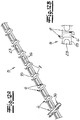
- FIG. 2 shows a formwork device 11 for the production of a component according to the invention.
- Receiving rails 5 were inserted into this formwork device 11 and the pipe 3 was inserted or snapped into place in the pipe receivers 4 of the receiving rails 5.
- the reinforcement elements 9 and the concrete 1 are in the state of Fig. 2 not yet applied or introduced.
- Fig. 2 shows that the pipe 3 is preferably and in the exemplary embodiment arranged in the form of a pipe register which has parallel pipe sections 12 and curved pipe sections 13 connecting the parallel pipe sections 12.
- deflection aid devices 14 are indicated for the bent pipe sections 13, but these are not shown in more concrete terms.
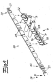
- the Fig. 3 shows a first embodiment of a receiving rail 5 according to the invention.
- the receiving rail 5 is U-shaped in cross section, with a base web 15 forming the U base and two transverse webs 16 arranged perpendicular to the base web 15 forming the U-legs.
- pipe receptacles 4 are provided in each transverse web and a pipe receptacle 4 in one transverse web 16 is aligned with a pipe receptacle 4 in the other transverse web 16, so that an inserted pipe 3 in the area of the pipe receptacles 4 is perpendicular to the longitudinal axis of the receiving rail 5 is arranged.
- Spacers 7 are connected to the underside of the base web 15.
- FIGS Figures 4a and 4b Two embodiments for such spacers 7 are shown in FIGS Figures 4a and 4b shown.
- the spacers 7 are connected to latching elements 17. These latching elements 17 can be latched with the receiving rail 5 in latching openings 18 present in the base web 15.
- the already locked state is in the lower rail section 19 in FIG Fig. 3 shown.
- the receiving rail 5 is in the embodiment according to Fig. 3 composed of two rail sections 19, 20 which can be connected to one another via connecting elements 21. It is also within the scope of the invention that a receiving rail 5 can be composed of more than two rail sections 19, 20.
- reinforcing ribs 22 are connected to the transverse webs 16 in the region of the pipe receptacles 4.
- the sections of the transverse webs 16 between the pipe receptacles 4 are expediently used to support reinforcement elements 9 or to support a reinforcement mat 10.
- these sections of the transverse webs 16 have openings 23 that promote the flow of concrete.
- the spacers 7 are connected to one another via bridge elements 24, and the latching elements 17 are arranged on these bridge elements 24.
- the spacers 7 preferably taper downwards in the exemplary embodiment.
- the spacers are expediently provided with recesses 25 at their tip or at their lower end, so that only point-like or line-like end sections 26 of the spacers 7 are visible on the front surface 2.
- the spacers 7 are integrally formed on the receiving rail 5.
- the spacers 7 are formed on the transverse webs 16 below the pipe receptacles 4.
- FIG. 6 Another embodiment of the invention shows Fig. 6 .
- the receiving rails 5 are here per se as in the embodiment of FIG Fig. 3 educated.
- the spacers 7 are arranged on separate spacer rails 27 or are formed in one piece.
- the spacer rails 27 are laid below the receiving rails 5 transversely to the receiving rails 5. It is within the scope of the invention that the spacer rails 27 are connected in the intersection areas with the receiving rail 5 via coupling elements not shown in detail.
- the one in the Fig. 7 The illustrated embodiment is similar to the embodiment according to Fig. 6 .
- spacer rails 27 are used.
- the spacer rails 27 are laid below the receiving rails 5, specifically parallel to the receiving rails 5.
- the receiving rails 5 can be connected to the spacer rails 27 by connecting elements not shown in detail.
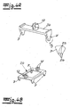
- FIG. 8a and 8b Another embodiment of a receiving rail 5 according to the invention is shown.
- a base web 15 is provided here and, in this case, only a single transverse web 16 is arranged perpendicular to this base web 15.
- the pipe receptacles 4 are provided.
- Downwardly directed spacers 7 are integrally formed on both sides of the base web 15.
- Reinforcing ribs 22 are moreover connected on each side of the transverse web 16.
- Fig. 9 shows an embodiment in which the receiving rail 5 as in the embodiment according to Figures 8a and 8b is designed.
- the tubes 3 received in the tube receptacles 4 are fixed with an additional fixing comb 28.
- the fixing comb 28 has receiving openings 29 for the tubes 3, which are arranged at a distance from the tube receivers 4.
- the fixing comb 28 is then slipped over the pipes 3 received in the pipe receptacles 4, so that the pipes 3 are clasped by the fixing comb 28 from above.
- the fixing comb 28 also has two comb sections 30, 31 which can be connected to one another and which can be connected to one another via connecting elements 21.
- the Figures 10a and 10b show a similar receiving rail 5 as that Figures 8a and 8b .
- the Figures 10a, b is the only transverse web 16 in contrast to the embodiment according to the Figures 8a and 8b not arranged centrally on the base web 15 but on one side of the base web 15.
- the Figure 10b shows, that Reinforcing ribs 22 are connected to the transverse web 16 on both sides of the transverse web 16.
- FIG. 11 Another embodiment of a receiving rail 5 according to the invention is shown in FIG Fig. 11 shown.
- the receiving rail 5 is again U-shaped.
- the base web 15 is oriented upwards and the spacers 7 are connected in one piece to the transverse webs 16 oriented downwards or towards the front surface 2.
- the pipe receptacles 4 are in turn provided in these transverse webs 16.
- FIG. 11 FIG. 12 also shows a connection element 32 which can be latched in a latching opening 18 of the base web 15 and can be connected to a reinforcing bar (not shown) with a clamp element 33.
- FIG. 12a The illustrated embodiment for a receiving rail according to the invention is similar to the embodiment according to Fig. 11 .
- additional locking lugs 6 are provided on the tube mounts.
- the locking lugs 6 are arranged diagonally offset to one another ( Figure 12b ) and enable a functionally reliable locking of the tube 3 in the tube receptacles 4.
- FIG. 12a it is also shown that, in addition, half-shell-shaped pipe support elements 34 can be inserted into the pipe receptacles 4. With the help of these pipe support elements 34, the pipe 3 received in the pipe receptacles 4 is additionally protected, in particular, against loads, for example by heavy reinforcement elements 9.
- a further embodiment of a receiving rail 5 is shown.
- This receiving rail 5 is preferably produced by injection molding.
- Two pipe clamps 36 for additional fixing of a pipe 3 are arranged between two aligned pipe receptacles 4.
- a transverse web (not shown) can optionally be provided between two pipe clamps 36, which, however, can easily be removed again if necessary so that the pipe receptacle 4 in question is available for a pipe 3 .
- Securing elements 38 projecting from the upper side of the receiving rail 5 and with bevels pointing away from the tube receivers 4 are provided on the side of the pipe receptacles 4. With the aid of these securing elements 38, it is ensured that reinforcing elements 9 resting on the receiving rail 5 cannot slip into the pipe receptacles 4.
Landscapes
- Engineering & Computer Science (AREA)
- Architecture (AREA)
- Physics & Mathematics (AREA)
- Electromagnetism (AREA)
- Civil Engineering (AREA)
- Structural Engineering (AREA)
- Forms Removed On Construction Sites Or Auxiliary Members Thereof (AREA)
- Manufacturing Of Tubular Articles Or Embedded Moulded Articles (AREA)
- Building Environments (AREA)
Description
- Die Erfindung betrifft ein Bauelement, vorzugsweise ein flächiges Bauelement und insbesondere ein flächiges Deckenelement oder ein flächiges Wandelement, wobei das Bauelement zumindest eine flächige Schicht aus einer erhärteten Vergussmasse, insbesondere aus Beton aufweist und wobei zumindest ein Heizungsrohr und/oder Kühlrohr für die Durchleitung eines fluiden Mediums in die erhärtete Vergussmasse eingebettet ist. Die Erfindung betrifft fernerhin ein Verfahren zur Herstellung eines solchen Bauelementes. - Ein erfindungsgemäßes flächiges Bauelement dient insbesondere zum Heizen und/oder Kühlen von Räumen, großvolumigen Behältern und dergleichen und insbesondere zum Heizen und/oder Kühlen der Innenräume von Gebäuden. Bei dem durch das Heizungsrohr und/oder Kühlrohr geleiteten fluiden Medium handelt es sich vorzugsweise um Wasser oder um ein anderes wässriges Medium. Grundsätzlich können aber auch Gase als fluide Medien durch das zumindest eine Rohr geleitet werden. Nachfolgend wird im Übrigen für den Begriff Heizungsrohr und/oder Kühlrohr auch lediglich der Begriff Rohr verwendet.
- Aus der Praxis sind flächige Bauelemente der eingangs genannten Art in verschiedenen Ausführungsformen bekannt. Bei diesen bekannten Bauelementen lässt häufig die Heiz- bzw. Kühlleistung zu wünschen übrig. Auch handelt es sich zumeist um aufwendig und kostspielig konstruierte Bauelemente. Aufgrund der vorgegebenen konstruktiven Verhältnisse sind Variationen insbesondere in Bezug auf die Bauelementabmessungen, den Verlegeabstand der Rohre, den Rohrdurchmesser, die höhenmäßige Anordnung der Rohre im Bauelement und dergleichen nicht ohne aufwendige Zusatzmaßnahmen möglich. Die Produktion der bekannten Bauelemente ist in der Regel in nachteilhafter Weise mit komplexen Produktionsabläufen verbunden.
- Aus
EP 2 213 808 A1 ist ein Bauelement der eingangs genannten Art bekannt. Hier wird ein Decken- oder Wandbauteil für Gebäude beschrieben, das mindestens eine Tragschicht aus Stahl- und/oder Spannbeton und mindestens eine Rohrleitung zum Zuführen eines Heiz- und/oder Kühlmediums umfasst. Ähnliche Bauteile bzw. Bauelemente sind auch ausUS 4 037 375 undEP 1 619 005 A2 bekannt. - Der Erfindung liegt das technische Problem zugrunde, ein Bauelement der eingangs genannten Art anzugeben, das einfach und wenig aufwendig, insbesondere industriell herstellbar ist, das zudem variabel und flexibel an die konkreten Gegebenheiten anpassbar ist und das außerdem auch eine optimale Heiz- bzw. Kühlleistung gewährleistet. Der Erfindung liegt weiterhin das technische Problem zugrunde, ein Verfahren zur Herstellung eines solchen Bauelementes anzugeben.
- Zur Lösung dieses technischen Problems lehrt die Erfindung ein Bauelement gemäß Anspruch 1.
- Der Abstand a wird von der Unterseite der Rohre aus gemessen. - Die Dicke der Oberflächenschicht zwischen dem zumindest einen Rohr und der vorderseitigen Oberfläche wird also durch die Höhe des zumindest einen Abstandshalters bestimmt. Es liegt im Rahmen der Erfindung, dass im fertigen Bauelement die Aufnahmeschienen in die erhärtete Vergussmasse eingebettet sind. Es liegt weiterhin im Rahmen der Erfindung, dass der zumindest eine an eine Aufnahmeschiene angeschlossene Abstandshalter die Oberflächenschicht aus der erhärteten Vergussmasse durchsetzt.
- Mit den erfindungsgemäßen Maßnahmen wird eine oberflächennahe Verlegung der Heiz- bzw. Kühlrohre im Bauelement realisiert, wobei ein relativ geringer Abstand eines Rohres zur vorderseitigen Oberfläche des Bauelementes funktionssicher und präzise eingestellt bzw. eingehalten werden kann und somit eine optimale Heiz- bzw. Kühlleistung erzielt werden kann. Nichtsdestoweniger kann ein erfindungsgemäßes Bauelement einfach, wenig aufwendig und kostengünstig gefertigt werden und es eignet sich vor allem für die industrielle Fertigung.
- Es wurde bereits eingangs dargelegt, dass das erfindungsgemäße Bauelement bzw. flächige Bauelement zum Heizen und/oder zum Kühlen von Räumen, großvolumigen Behältern und dergleichen eingesetzt werden kann. Vorzugsweise wird das flächige Bauelement zum Heizen und/oder Kühlen der Innenräume eines Gebäudes eingesetzt. Bei dem flächigen Bauelement handelt es sich insbesondere um ein flächiges Deckenelement oder ein flächiges Wandelement, das bevorzugt zur Beheizung oder Kühlung der Innenflächen von Räumen eingesetzt wird. Besonders bevorzugt handelt es sich bei dem erfindungsgemäßen flächigen Bauelement um ein flächiges Deckenelement. Es liegt auch im Rahmen der Erfindung, dass das Bauelement bzw. das flächige Bauelement als Absorber, insbesondere als Solarabsorber eingesetzt werden kann und dass dann das fluide Medium in dem zumindest einen Rohr Energie bzw. Wärme von außen aufnehmen kann. Auch diese Einsatzmöglichkeit ist mit dem Begriff Kühlrohr umfasst. - Vorderseitige Oberfläche des Bauelementes meint im Rahmen der Erfindung im Übrigen die dem zu heizenden bzw. dem zu kühlenden Raum zugewandte Oberfläche des Bauelementes.
- Nach einer bevorzugten Ausführungsform der Erfindung weist das erfindungsgemäße Bauelement bzw. flächige Bauelement eine rechteckige Fläche bzw. vorderseitige Oberfläche auf. Grundsätzlich sind aber auch andere geometrische Ausgestaltungen des Bauelementes möglich. Empfohlenermaßen beträgt die Fläche bzw. vorderseitige Oberfläche eines erfindungsgemäßen Bauelementes 4 bis 16 m2 und bevorzugt 5 bis 15 m2. Die Länge eines erfindungsgemäßen flächigen Bauelementes beträgt vorzugsweise 3 bis 9 m und bevorzugt 4 bis 8 m. Es empfiehlt sich, dass die Breite des flächigen Bauelementes 1 bis 5 m, bevorzugt 1,5 bis 4 m beträgt. - Die erfindungsgemäßen flächigen Bauelemente können als vorgefertigte Fertigelemente zum Montageort transportiert werden. Es ist aber auch möglich, dass die Bauelemente gleichsam in situ bzw. am Montageort hergestellt bzw. vergossen werden. - Bei der für das erfindungsgemäße Bauelement eingesetzten Vergussmasse handelt es sich zweckmäßigerweise um eine zementhaltige bzw. auf Zement basierende Vergussmasse, insbesondere um Beton.
- Das zumindest eine in dem Bauelement vorgesehene Rohr ist nach bevorzugter Ausführungsform in Form eines Rohrregisters ausgebildet. Dabei weist das zumindest eine Rohr parallele bzw. im Wesentlichen parallele Rohrabschnitte auf und gebogene Rohrabschnitte, die die parallelen bzw. im Wesentlichen parallelen Rohrabschnitte miteinander verbinden. Bei den erfindungsgemäß eingesetzten Rohren handelt es sich empfohlenermaßen um Kunststoffrohre. Vorzugsweise haben die Rohre einen runden Querschnitt und insbesondere einen kreisförmigen Querschnitt. Grundsätzlich sind aber auch andere Querschnittsformen möglich. Der Außendurchmesser der Rohre beträgt zweckmäßigerweise 10 bis 25 mm und bevorzugt 12 bis 20 mm. Die Wandstärke der Rohre beträgt empfohlenermaßen 1 bis 3 mm. Mit Rohr ist im Rahmen der Erfindung grundsätzlich jeder Kanal gemeint, der sich für die Durchführung des fluiden Mediums eignet.
- Es liegt im Rahmen der Erfindung, dass die Aufnahmeschienen bzw. linearen Aufnahmeschienen aus einem nichtmetallischen Werkstoff, insbesondere aus Kunststoff bzw. im Wesentlichen aus Kunststoff bestehen. Erfindungsgemäß wird eine Aufnahmeschiene einstückig durch Extrusion oder Spritzgießen erzeugt. Eine bevorzugte Ausführungsform ist dadurch gekennzeichnet, dass eine Aufnahmeschiene aus einer Mehrzahl von zusammengesteckten Schienenabschnitten bzw. linearen Schienenabschnitten besteht. Jeder Schienenabschnitt weist dann bevorzugt eine Mehrzahl von Rohraufnahmen auf. Die einzelnen Schienenabschnitte werden vorzugsweise einstückig durch Extrusion oder Spritzgießen hergestellt.
- Separat verlegbare bzw. montierbare Aufnahmeschienen meint im Rahmen der Erfindung insbesondere, dass die Aufnahmeschienen bzw. die linearen Aufnahmeschienen grundsätzlich einzeln in den gewünschten Schienenabständen bei der Herstellung des Bauelementes verlegt werden können. Das schließt aber nicht aus, dass auch ein Aggregat aus einer Mehrzahl von Aufnahmeschienen und zumindest einem in den Rohraufnahmen der Auflageschienen aufgenommenen Rohr - das also die einzelnen Aufnahmeschienen miteinander verbindet - bei der Erzeugung des Bauelementes verlegt werden kann. Ausgeschlossen ist auch nicht die Verlegung eines weiter unten noch erläuterten Aggregates aus bereits miteinander verbundenen Auflageschienen und Abstandshalterschienen. Es liegt aber im Rahmen der Erfindung, dass die Aufnahmeschienen einzeln bzw. separat hergestellt werden und grundsätzlich einzeln und separat verlegbar bzw. montierbar sind. Die Erfindung bezieht sich insbesondere nicht auf eine einstückige, Rohraufnahmen aufweisende Kunststoffmatte mit Längs- und Querstreben.
- Dass das zumindest eine Rohr im Bereich der vorderseitigen Oberfläche des Bauelementes angeordnet ist, meint im Rahmen der Erfindung insbesondere, dass das Rohr in dem in Bezug auf die gesamte Dicke des Bauelementes vorderen Drittel, vorzugsweise im vorderen Viertel und besonders bevorzugt im vorderen Fünftel des Bauelementes angeordnet ist. Eine bevorzugte Ausführungsform der Erfindung ist dadurch gekennzeichnet, dass der Abstand a des zumindest einen Rohres von der vorderseitigen Oberfläche 3 bis 18 %, bevorzugt 5 bis 14 % und besonders bevorzugt 6 bis 12 % der Dicke D des Bauelementes beträgt. Dicke D meint dabei den Abstand der vorderseitigen Oberfläche von der rückseitigen Oberfläche des Bauelementes. Es empfiehlt sich, dass der Abstand a 5 bis 35 mm, bevorzugt 10 bis 28 mm und sehr bevorzugt 12 bis 25 mm beträgt. Die Höhe h eines Abstandshalters beträgt empfohlenermaßen 7 bis 23 mm, bevorzugt 9 bis 21 mm und besonders bevorzugt 11 bis 19 mm. Höhe h meint dabei die Erstreckung des Abstandshalters senkrecht zur vorderseitigen Oberfläche des Bauelementes, zweckmäßigerweise bis zur Unterkante bzw. Unterseite der zugeordneten Aufnahmeschiene. Zweckmäßigerweise beträgt die Dicke D des Bauelementes 120 bis 300 mm, vorzugsweise 140 bis 250 mm und bevorzugt 170 bis 230 mm.
- Nach besonders bevorzugter Ausführungsform der Erfindung ergibt sich für das Verhältnis D/d • a ein Wert von 0,3 bis 1,7, bevorzugt 0,4 bis 1,5 und sehr bevorzugt 0,5 bis 1,3. d meint dabei den Außendurchmesser des zumindest einen Rohres, D meint die Dicke des Bauelementes und a meint den Abstand des zumindest einen Rohres von der vorderseitigen Oberfläche.
- Eine empfohlene Ausführungsform der Erfindung ist dadurch gekennzeichnet, dass das Verhältnis (A/D) des Abstandes A der Oberseite bzw. der Oberkante der Aufnahmeschienen zur vorderseitigen Oberfläche des Bauelementes zur Dicke D des Bauelementes 0,1 bis 0,3, vorzugweise 0,12 bis 0,25 und bevorzugt 0,13 bis 0,21 beträgt. Erfindungsgemäß liegt zumindest ein Bewehrungselement an der Oberseite bzw. Oberkante der Aufnahmeschienen an. Bei dem Bewehrungselement bzw. bei den Bewehrungselementen kann es sich insbesondere um eine Bewehrungsmatte oder um Bewehrungsstäbe handeln. Das zumindest eine Bewehrungselement besteht vorzugsweise aus Metall bzw. im Wesentlichen aus Metall und besonders bevorzugt aus Stahl bzw. im Wesentlichen aus Stahl. - Hervorzuheben ist, dass den Aufnahmeschienen im Rahmen der Erfindung zweckmäßigerweise eine Doppelfunktion zukommt, in dem sie einerseits der Rohraufnahme bzw. Rohrfixierung dienen und andererseits eine Ablagefläche für zumindest ein Bewehrungselement zur Verfügung stellen. Die Aufnahmeschienen haben dann also auch die Funktion einer Höhenfixierung für die Bewehrung.
- Vorzugsweise ist eine Rohraufnahme für die formschlüssige Aufnahme eines Rohres eingerichtet. Nach einer Ausführungsform der Erfindung wird ein Rohr in einer Rohraufnahme mittels einer Rastverbindung arretiert bzw. fixiert.
- Erfindungsgemäß weist eine Aufnahmeschiene einen Basissteg und zumindest einen an den Basissteg angeschlossenen und quer zu dem Basissteg angeordneten Quersteg auf. Der zumindest eine Quersteg ist zweckmäßigerweise senkrecht bzw. im Wesentlichen senkrecht zum Basissteg angeordnet. Erfindungsgemäß ist in dem zumindest einen Quersteg eine Mehrzahl von Rohraufnahmen vorgesehen.
- Eine besonders empfohlene Ausführungsform der Erfindung ist dadurch gekennzeichnet, dass eine Aufnahmeschiene im Querschnitt U-förmig ausgebildet ist, wobei zwei quer zu dem Basissteg angeordnete Querstege vorgesehen sind. Es liegt im Rahmen der Erfindung, dass die Rohraufnahmen in den beiden Querstegen vorgesehen sind. Zweckmäßigerweise sind die Querstege senkrecht bzw. im Wesentlichen senkrecht zum Basissteg angeordnet. Der Basissteg bildet die U-Basis und die beiden Querstege bilden die U-Schenkel der U-förmig ausgebildeten Aufnahmeschiene. Gemäß einer Ausführungsvariante ist die U-Basis einer Aufnahmeschiene zur vorderseitigen Oberfläche des Bauelementes hin orientiert. Zweckmäßigerweise ist in jedem Quersteg einer U-förmigen Aufnahmeschiene eine Mehrzahl von Rohraufnahmen vorgesehen. Zumindest für einen Teil bzw. für einen Großteil dieser Rohraufnahmen gilt, dass eine erste in dem einen Quersteg angeordnete Rohraufnahme mit einer zweiten in dem anderen Quersteg angeordneten Rohraufnahme fluchtet. Vorzugsweise ist ein in zwei einander zugeordnete fluchtende Rohraufnahmen eingelegtes Rohr quer und bevorzugt senkrecht bzw. im Wesentlichen senkrecht zur Längsrichtung bzw. Längsachse der Aufnahmeschiene angeordnet.
- Eine sehr bevorzugte Ausführungsform der Erfindung zeichnet sich dadurch aus, dass eine Aufnahmeschiene eine Mehrzahl von an den Basissteg und/oder an die Querstege angeschlossenen Abstandshaltern aufweist. Wenn nach einer Ausführungsvariante der Basissteg zur vorderseitigen Oberfläche des Bauelementes hin orientiert ist, sind die Abstandshalter zweckmäßigerweise an der den Querstegen abgewandten Unterseite des Basissteges angeschlossen. Nach einer empfohlenen Ausführungsvariante ist an einer Aufnahmeschiene eine Mehrzahl von Abstandshaltern einstückig angeformt. Die Aufnahmeschienen mit den einstückig angeformten Abstandshaltern bestehen vorzugsweise aus Kunststoff und werden zweckmäßigerweise durch Extrusion oder Spritzgießen hergestellt. Die Abstandshalter können an dem Basissteg oder an dem zumindest einen Quersteg einer Aufnahmeschiene einstückig angeformt sein. Nach einer anderen bevorzugten Ausführungsform der Erfindung ist an einer Aufnahmeschiene eine Mehrzahl von Abstandshaltern über Rastverbindungen, insbesondere über lösbare Rastverbindungen angeschlossen. Zweckmäßigerweise sind diese Abstandshalter an dem Basissteg bzw. an der zur vorderseitigen Oberfläche hin orientierten Unterseite des Basissteges angeschlossen. Der Basissteg verfügt dazu bevorzugt über Rastöffnungen, in denen Rastelemente der Abstandshalter eingerastet werden können.
- Vorzugsweise ist in einer Aufnahmeschiene, insbesondere in den Basissteg und/oder in dem zumindest einen Quersteg einer Aufnahmeschiene eine Mehrzahl von Durchbrüchen bzw. Öffnungen für die Vergussmasse eingebracht. Diese Durchbrüche bzw. Öffnungen ermöglichen ein besseres Fließen der eingebrachten noch nicht erhärteten Vergussmasse.
- In besonders vorteilhafter Ausgestaltung der Erfindung ist vorgesehen, dass sich ein an einer Aufnahmeschiene angeschlossener Abstandshalter zur vorderseitigen Oberfläche des Bauelementes hin verjüngt. Zweckmäßigerweise verjüngt sich ein Abstandshalter mit der Maßgabe, dass er an der vorderseitigen Oberfläche des Bauelementes spitz zuläuft. Nach einer empfohlenen Ausführungsvariante hat ein Abstandshalter zumindest im Bereich der vorderseitigen Oberfläche des Bauelementes einen dreieckförmigen Querschnitt. Es liegt im Rahmen der Erfindung, dass an der vorderseitigen Oberfläche des Bauelementes lediglich kleine bzw. schmale punktförmige oder linienförmige Bereiche der Abstandshalter vorhanden bzw. sichtbar sind.
- Eine sehr bevorzugte Ausführungsform der Erfindung ist dadurch gekennzeichnet, dass zumindest ein Teil der Abstandshalter, vorzugsweise alle Abstandshalter unterhalb der Rohraufnahmen an einer Aufnahmeschiene angeschlossen sind. Dadurch wird eine höhere Stabilität der Aufnahmeschiene bei der Montage eines Rohres gewährleistet und es wird insbesondere ein Durchbiegen bzw. Durchdrücken der Aufnahmeschiene verhindert.
- Gegenstand der Erfindung ist auch ein Verfahren zur Herstellung eines Bauelementes gemäß Anspruch 13. Dieses Verfahren umfasst auch eine Ausführungsform, bei der das zumindest eine Rohr schon in die Aufnahmeschienen eingebracht ist und bei der das Aggregat aus dem zumindest einen Rohr und den Aufnahmeschienen auf dem Boden der Schalungseinrichtung aufgebracht wird.
- Eine Ausführungsform des erfindungsgemäßen Verfahrens ist dadurch gekennzeichnet, dass zunächst (werksseitig) lediglich ein Teil der für das Bauelement erforderlichen Vergussmasse in die Schalungseinrichtung eingebracht wird und somit lediglich ein Teil der Dicke D des fertigen Bauelementes mit Vergussmasse verfüllt wird. Der Rest der Vergussmasse wird nach dieser Ausführungsform vor Ort bzw. am Montageort eingebracht bzw. aufgebracht. Zweckmäßigerweise wird zunächst (werksseitig) Vergussmasse mit der Maßgabe aufgebracht, dass die Aufnahmeschienen und das zumindest eine Rohr in die Vergussmasse eingebettet wird und dass das zumindest eine auf den Aufnahmeschienen aufliegende Bewehrungselement zumindest teilweise in die Vergussmasse eingebettet wird. Aufgrund dieser lediglich teilweisen Fertigstellung des Bauelementes hat man zunächst ein relativ leichtgewichtiges einfach zu handhabendes Basiselement, das später am Montageort mit der noch fehlenden Vergussmasse versehen wird. - Nach einer anderen Ausführungsform des erfindungsgemäßen Verfahrens kann aber auch die gesamte Vergussmasse oder der größte Teil der Vergussmasse werksseitig eingebracht bzw. aufgebracht werden.
- Der Erfindung liegt die Erkenntnis zugrunde, dass ein erfindungsgemäßes Bauelement auf sehr einfache, wenig aufwendige und kostengünstige Weise herstellbar ist. Die Herstellung der erfindungsgemäßen Bauelemente lässt sich problemlos in die an sich üblichen Produktionsabläufe für Betonteile in Betonfertigteilwerken einbinden. Die Bauelemente eignen sich hervorragend für eine industrielle Fertigung. Die erfindungsgemäßen Bauelemente sind auf einfache Weise flexibel und variabel an gewünschte Bauelementabmessungen Rohrverlegeabstände, Rohrdurchmesser, sowie an die Höhenlage des zumindest einen Rohres und dergleichen anpassbar. In der vorderseitigen Oberfläche des Bauelementes sind nur kleine punktartige bzw. linienartige Endbereiche der Abstandshalter erkennbar, so dass sich hier ein Vorteil für Sichtbetonoberflächen von Bauelementen ergibt. Weiterhin ist hervorzuheben, dass sich die erfindungsgemäßen flächigen Bauelemente auch durch eine hervorragende Heizleistung und/oder Kühlleistung auszeichnen. Das wird vor allem auch durch die einfache und funktionssichere Einbringung der Rohre in oberflächennahe Bereiche des Bauelementes gewährleistet. Insgesamt zeichnet sich die Erfindung durch geringen Aufwand und durch geringe Kosten aus.
- Nachfolgend wird die Erfindung anhand einer lediglich ein Ausführungsbeispiel darstellenden Zeichnung näher erläutert. Es zeigen in schematischer Darstellung:
- Fig.
- einen Schnitt durch ein erfindungsgemäßes Bauelement,
- Fig. 2
- eine perspektivische Ansicht einer Schalungseinrichtung mit eingebrachten Komponenten des erfindungsgemäßen Bauelementes,
- Fig. 3
- eine perspektivische Ansicht einer Ausführungsform einer Aufnahmeschiene für das erfindungsgemäße Bauelement,
- Fig. 4a
- einen Abstandshalter für eine Aufnahmeschiene gemäß
Fig. 3 in einer ersten Ausführungsform, - Fig. 4b
- den Gegenstand nach
Fig. 4a in einer zweiten Ausführungsform, - Fig. 5
- eine perspektivische Darstellung einer weiteren Ausführungsform einer Aufnahmeschiene,
- Fig. 6
- eine perspektivische Darstellung einer anderen Ausführungsform von Aufnahmeschienen mit Abstandshaltern,
- Fig. 7
- den Gegenstand gemäß
Fig. 5 in einer zusätzlichen Ausführungsform, - Fig. 8a
- eine weitere Ausführungsvariante einer erfindungsgemäßen Aufnahmeschiene,
- Fig. 8b
- eine Draufsicht auf den Gegenstand nach
Fig. 8a , - Fig. 9
- den Gegenstand gemäß
Fig. 8a mit einer zusätzlichen Komponente, - Fig. 10a
- eine perspektivische Ansicht einer weiteren Ausführungsform einer Aufnahmeschiene,
- Fig. 10b
- einen Schnitt durch den Gegenstand nach
Fig. 10a , - Fig. 11
- eine perspektivische Darstellung einer zusätzlichen Ausführungsform einer Aufnahmeschiene,
- Fig. 12a
- den Gegenstand gemäß
Fig. 11 in einer weiteren Ausführungsform, - Fig. 12b
- eine Draufsicht auf den Gegenstand nach
Fig. 12a , - Fig. 13
- eine perspektivische Ansicht einer weiteren Ausführungsform einer Aufnahmeschiene und
- Fig. 14
- eine perspektivische Darstellung einer zusätzlichen Ausführungsvariante einer Aufnahmeschiene.
-
Fig. 1 zeigt ein erfindungsgemäßes flächiges Bauelement im Schnitt, das vorzugsweise als flächiges Deckenelement zur Auskleidung der Decke eines nicht näher dargestellten Raums dient. Das Bauelement besteht zum größten Teil aus einer erhärteten Vergussmasse, die vorzugsweise und im Ausführungsbeispiel aus Beton 1 besteht. Im Bereich der vorderseitigen Oberfläche 2 des Bauelementes ist ein als Heizungsrohr ausgebildetes Rohr 3 für die Durchleitung eines fluiden Heizmediums in den erhärteten Beton 1 eingebettet. Das Rohr 3 ist dabei in Rohraufnahmen 4 aufgenommen, die in einer Mehrzahl von linearen Aufnahmeschienen 5 vorgesehen sind. Nach einer bevorzugten Ausführungsform ist die inFig. 1 dargestellte Aufnahmeschiene 5 im Querschnitt U-förmig ausgebildet. Verschiedene Ausführungsformen solcher U-förmig ausgebildeter Aufnahmeschienen 5 werden weiter unten erläutert. Es ist inFig. 1 erkennbar, dass eine lineare Aufnahmeschiene 5 eine Mehrzahl von Rohraufnahmen 4 aufweist. Im Ausführungsbeispiel nachFig. 1 ist das Rohr 3 mit Hilfe von Rastnasen 6 in den Rohraufnahmen 4 verrastet. An die Aufnahmeschiene 5 sind Abstandshalter 7 angeschlossen, die den Abstand a des Rohres 3 zu der vorderseitigen Oberfläche 2 des Bauelementes vorgeben. Der Abstand a wird dabei von der Unterseite des Rohres 3 ausgemessen. Die Abstandshalter 7 weisen eine Höhe h auf, wobei diese Höhe h senkrecht zu der vorderseitigen Oberfläche 2 als Abstand der vorderseitigen Oberfläche 2 von der Unterkante bzw. Unterseite der übrigen Aufnahmeschiene 5 gemessen wird. Zwischen dem Rohr 3 bzw. der Aufnahmeschiene 5 und der vorderseitigen Oberfläche 2 des Bauelementes ist eine relativ dünne Oberflächenschicht 8 aus dem erhärteten Beton 1 angeordnet. Die Abstandshalter 7 durchsetzen diese Oberflächenschicht 8. Vorzugsweise und im Ausführungsbeispiel verjüngen sich die Abstandshalter 7 zur vorderseitigen Oberfläche 2 hin, so dass an der vorderseitigen Oberfläche lediglich die Spitzen bzw. punktförmige oder linienförmige Endbereiche der Abstandshalter 7 sichtbar sind. InFig. 1 ist weiter dargestellt, dass das erfindungsgemäße Bauelemente mit Bewehrungselementen 9 bewehrt ist. Ein gitterartig ausgebildetes Bewehrungselement 9, insbesondere ein als Bewehrungsmatte 10 ausgebildetes Bewehrungselement 9 liegt unmittelbar auf den Aufnahmeschienen 5 auf, und zwar in den Bereichen der Aufnahmeschiene 5 zwischen den Rohraufnahmen 4. In dem Schnitt vonFig. 1 ist lediglich eine Aufnahmeschiene 5 erkennbar. Es sind aber vorzugsweise mehrere Aufnahmeschienen 5 parallel zueinander angeordnet, die allesamt Rohraufnahmen 4 für das Rohr 3 aufweisen. Mit D ist in derFig. 1 im Übrigen die gesamte Dicke des Bauelementes bezeichnet. Der Außendurchmesser des Rohres 3 wird mit d angegeben und mit A wird der Abstand der Oberseite bzw. Oberkante der Aufnahmeschiene 5 zur vorderseitigen Oberfläche 2 des Bauelementes bezeichnet. In derFig. 1 ist weiterhin erkennbar, dass an der Unterseite der Aufnahmeschiene 5 dreieckförmige Aussparungen 37 vorgesehen sind, die an nicht dargestellte Fasen einer Schalungseinrichtung 11 angepasst sind. - Die perspektivische Ansicht gemäß
Fig. 2 zeigt eine Schalungseinrichtung 11 für die Herstellung eines erfindungsgemäßen Bauelementes. In diese Schalungseinrichtung 11 wurden Aufnahmeschienen 5 und in die Rohraufnahmen 4 der Aufnahmeschienen 5 wurde das Rohr 3 eingelegt bzw. eingerastet. Die Bewehrungselemente 9 und der Beton 1 sind in dem Zustand derFig. 2 noch nicht aufgebracht bzw. eingebracht.Fig. 2 zeigt, dass das Rohr 3 vorzugsweise und im Ausführungsbeispiel in Form eines Rohrregisters angeordnet ist, das parallele Rohrabschnitte 12 und die parallelen Rohrabschnitte 12 verbindende gebogene Rohrabschnitte 13 aufweist. InFig. 2 sind im Übrigen Umlenkhilfeeinrichtungen 14 für die gebogenen Rohrabschnitte 13 angedeutet, die aber nicht konkreter dargestellt sind. - Die
Fig. 3 zeigt eine erste Ausführungsform einer erfindungsgemäßen Aufnahmeschiene 5. Die Aufnahmeschiene 5 ist hier im Querschnitt U-förmig ausgebildet, wobei ein Basissteg 15 die U-Basis bildet und wobei zwei senkrecht zu dem Basissteg 15 angeordnete Querstege 16 die U-Schenkel bilden. Es ist erkennbar, dass Rohraufnahmen 4 in jedem Quersteg vorgesehen sind und dabei fluchtet jeweils eine Rohraufnahme 4 in dem einen Quersteg 16 mit einer Rohraufnahme 4 in dem anderen Quersteg 16, so dass ein eingelegtes Rohr 3 im Bereich der Rohraufnahmen 4 senkrecht zur Längsachse der Aufnahmeschiene 5 angeordnet ist. An der Unterseite des Basissteges 15 sind Abstandshalter 7 angeschlossen. Zwei Ausführungsformen für solche Abstandshalter 7 sind in denFig. 4a und 4b dargestellt. Im Ausführungsbeispiel nach denFig. 3 ,4a und 4b sind die Abstandshalter 7 mit Rastelementen 17 verbunden. Diese Rastelemente 17 können in in dem Basissteg 15 vorhandenen Rastöffnungen 18 mit der Aufnahmeschiene 5 verrastet werden. Der bereits verrastete Zustand ist in dem unteren Schienenabschnitt 19 inFig. 3 dargestellt. Die Aufnahmeschiene 5 ist im Ausführungsbeispiel nachFig. 3 aus zwei Schienenabschnitten 19, 20 zusammengesetzt, die über Verbindungselemente 21 miteinander verbunden werden können. Es liegt auch im Rahmen der Erfindung, dass eine Aufnahmeschiene 5 aus mehr als zwei Schienenabschnitten 19, 20 zusammengesetzt sein kann. Dem oberen vergrößerten Ausschnitt derFig. 3 ist im Übrigen entnehmbar, dass an die Querstege 16 im Bereich der Rohraufnahmen 4 Verstärkungsrippen 22 angeschlossen sind. Die Abschnitte der Querstege 16 zwischen den Rohraufnahmen 4 dienen zweckmäßigerweise der Auflage von Bewehrungselementen 9 bzw. der Auflage einer Bewehrungsmatte 10. Diese Abschnitte der Querstege 16 weisen im Ausführungsbeispiel wie auch der Basissteg 15 Durchbrüche 23 auf, die den Betonfluss begünstigen. - In den
Fig. 4a und 4b ist gezeigt, dass die Abstandshalter 7 über Brückenelemente 24 miteinander verbunden sind, und auf diesen Brückenelementen 24 sind die Rastelemente 17 angeordnet. In diesen Figuren ist auch erkennbar, dass sich die Abstandshalter 7 vorzugsweise und im Ausführungsbeispiel nach unten hin verjüngen. Außerdem ist in dem vergrößerten Ausschnitt derFig. 4a eine bevorzugte Ausführungsform dargestellt, bei der die Abstandshalter zweckmäßigerweise an ihrer Spitze bzw. an ihrem unteren Ende mit Ausnehmungen 25 versehen sind, so dass an der vorderseitigen Oberfläche 2 lediglich punktartige bzw. linienartige Endabschnitte 26 der Abstandshalter 7 sichtbar sind. In derFig. 5 ist eine weitere Ausführungsform einer erfindungsgemäßen Aufnahmeschiene 5 dargestellt. Hier sind die Abstandshalter 7 einstückig an die Aufnahmeschiene 5 angeformt. Die Abstandshalter 7 sind dabei unterhalb der Rohraufnahmen 4 an den Querstegen 16 angeformt. - Eine weitere Ausführungsform der Erfindung zeigt die
Fig. 6 . Die Aufnahmeschienen 5 sind hier an sich wie im Ausführungsbeispiel derFig. 3 ausgebildet. Die Abstandshalter 7 sind in diesem Fall aber an separaten Abstandshalterschienen 27 angeordnet bzw. einstückig angeformt. Die Abstandshalterschienen 27 werden unterhalb der Aufnahmeschienen 5 quer zu den Aufnahmeschienen 5 verlegt. Es liegt im Rahmen der Erfindung, dass die Abstandshalterschienen 27 in den Kreuzungsbereichen mit der Aufnahmeschiene 5 über nicht näher dargestellten Kupplungselemente verbunden sind. - Die in der
Fig. 7 dargestellte Ausführungsform ähnelt der Ausführungsform nachFig. 6 . Auch hier wird mit Abstandshalterschienen 27 gearbeitet. Die Abstandshalterschienen 27 sind in diesem Ausführungsbeispiel unterhalb der Aufnahmeschienen 5, und zwar parallel zu den Aufnahmeschienen 5 verlegt. Auch hier können die Aufnahmeschienen 5 durch nicht näher dargestellte Verbindungselemente mit den Abstandshalterschienen 27 verbunden sein. - In den
Fig. 8a und 8b ist eine andere Ausführungsform einer erfindungsgemäßen Aufnahmeschiene 5 gezeigt. Hier ist ein Basissteg 15 vorgesehen und zu diesem Basissteg 15 ist in diesem Fall nur ein einziger Quersteg 16 senkrecht angeordnet. In diesem Quersteg 16 sind die Rohraufnahmen 4 vorgesehen. An beiden Seiten des Basissteges 15 sind nach unten gerichtete Abstandshalter 7 einstückig angeformt. Auf beiden Seiten der Rohraufnahmen 4 sind Durchbrüche 23 für die Förderung des Betonflusses in dem Basissteg 15 vorhanden. Verstärkungsrippen 22 sind im Übrigen auf jeder Seite des Quersteges 16 angeschlossen. -
Fig. 9 zeigt eine Ausführungsform, bei der die Aufnahmeschiene 5 wie im Ausführungsbeispiel nach denFig. 8a und 8b ausgestaltet ist. Hier werden die in den Rohraufnahmen 4 aufgenommenen Rohre 3 aber mit einem zusätzlichen Fixierungskamm 28 fixiert. Der Fixierungskamm 28 weist im Abstand der Rohraufnahmen 4 zueinander angeordnete Aufnahmeöffnungen 29 für die Rohre 3 auf. Der Fixierungskamm 28 wird dann über die in den Rohraufnahmen 4 aufgenommenen Rohre 3 gestülpt, so dass die Rohre 3 von oben von dem Fixierungskamm 28 umklammert werden. In derFig. 9 ist außerdem dargestellt, dass auch der Fixierungskamm 28 zwei miteinander verbindbare Kammabschnitte 30, 31 aufweist, die über Verbindungselemente 21 miteinander verbindbar sind. - Die
Fig. 10a und 10b zeigen eine ähnliche Aufnahmeschiene 5 wie dieFig. 8a und 8b . In derFig. 10a, b ist jedoch der einzige Quersteg 16 im Gegensatz zur Ausführungsform nach denFig. 8a und 8b nicht mittig auf dem Basissteg 15 angeordnet sondern an einer Seite des Basissteges 15. DieFig. 10b zeigt, dass beidseitig des Quersteges 16 Verstärkungsrippen 22 an den Quersteg 16 angeschlossen sind. - Eine weitere Ausführungsform einer erfindungsgemäßen Aufnahmeschiene 5 ist in der
Fig. 11 dargestellt. Hier ist die Aufnahmeschiene 5 wiederum U-förmig ausgebildet. Allerdings ist hier der Basissteg 15 nach oben hin orientiert und die Abstandshalter 7 sind an den nach unten bzw. zur vorderseitigen Oberfläche 2 hin orientierten Querstegen 16 einstückig angeschlossen. Die Rohraufnahmen 4 sind wiederum in diesen Querstegen 16 vorgesehen.Fig. 11 zeigt im Übrigen ein Anschlusselement 32, das in einer Rastöffnung 18 des Basissteges 15 verrastbar ist und mit einem Klammerelement 33 an einem nicht dargestellten Bewehrungsstab anschließbar ist. - Die in den
Fig. 12a und 12b dargestellte Ausführungsform für eine erfindungsgemäße Aufnahmeschiene ähnelt der Ausführungsform nachFig. 11 . Allerdings sind im Ausführungsbeispiel gemäßFig. 12a und 12b an den Rohraufnahmen 4 zusätzliche Rastnasen 6 vorgesehen. Die Rastnasen 6 sind diagonal versetzt zueinander angeordnet (Fig. 12b ) und ermöglichen ein funktionssicheres Verrasten des Rohres 3 in den Rohraufnahmen 4. In derFig. 12a ist weiterhin dargestellt, dass zusätzlich halbschalenförmige Rohrauflageelemente 34 in die Rohraufnahmen 4 eingelegt werden können. Mit Hilfe dieser Rohrauflageelemente 34 wird das in den Rohraufnahmen 4 aufgenommene Rohr 3 zusätzlich insbesondere gegenüber Belastungen, beispielsweise durch schwere Bewehrungselemente 9 geschützt. - In
Fig. 13 ist eine weitere Ausführungsform einer Aufnahmeschiene 5 dargestellt. Diese Aufnahmeschiene 5 wird vorzugsweise durch Spritzgießen hergestellt. Zwischen zwei fluchtenden Rohraufnahmen 4 sind hier jeweils zwei Rohrklammern 36 zur zusätzlichen Fixierung eines Rohres 3 angeordnet. Damit auf der Aufnahmeschiene 5 aufliegende - inFig. 13 nicht dargestellte - Bewehrungselemente 9 nicht in nicht belegte Rohraufnahmen 4 rutschen, kann zwischen zwei Rohrklammern 36 optional ein nicht dargestellter Quersteg vorgesehen sein, der jedoch im Bedarfsfall auch leicht wieder entfernt werden kann, so dass die betreffende Rohraufnahme 4 für ein Rohr 3 zur Verfügung steht. - Bei der Ausführungsvariante nach
Fig. 14 sind seitlich der Rohraufnahmen 4 aus der Oberseite der Aufnahmeschiene 5 vorkragende Sicherungselemente 38 mit von den Rohraufnahmen 4 wegweisenden Schrägen vorgesehen. Mit Hilfe dieser Sicherungselemente 38 wird gewährleistet, dass auf der Aufnahmeschiene 5 aufliegende Bewehrungselemente 9 nicht in die Rohraufnahmen 4 rutschen können.
Claims (13)
- Bauelement, vorzugsweise flächiges Bauelement, insbesondere flächiges Deckenelement oder Wandelement, wobei das Bauelement zumindest eine flächige Schicht aus einer erhärteten Vergussmasse, insbesondere aus Beton (1) aufweist,
wobei im Bereich der vorderseitigen Oberfläche (2) des Bauelementes zumindest ein Heizungsrohr und/oder Kühlrohr für die Durchleitung eines fluiden Mediums in die erhärtete Vergussmasse eingebettet ist, wobei das zumindest eine Rohr (3) in Rohraufnahmen (4) aufgenommen ist, die in einer Mehrzahl von Aufnahmeschienen, insbesondere linearen Aufnahmeschienen (5) vorgesehen sind,
wobei eine Aufnahmeschiene (5) eine Mehrzahl solcher Rohraufnahmen (4) aufweist, wobei an eine Aufnahmeschiene (5) zumindest ein Abstandshalter (7) angeschlossen ist, der den Abstand a des zumindest einen Rohres (3) zu der vorderseitigen Oberfläche (2) des Bauelementes vorgibt und wobei zwischen dem zumindest einen Rohr (3) und der vorderseitigen Oberfläche (2) eine Oberflächenschicht (8) aus der erhärteten Vergussmasse angeordnet ist
und wobei eine Aufnahmeschiene (5) einen Basissteg (15) und zumindest einen an den Basissteg (15) angeschlossenen und quer zum Basissteg (15) angeordneten Quersteg (16) aufweist und wobei eine Mehrzahl von Rohraufnahmen (4) in dem zumindest einen Quersteg (16) vorgesehen ist, wobei die Aufnahmeschiene (5) lediglich Rohraufnahmen (4) aufweist, welche zur Rückseite des Bauelementes hin für die Einführung von Rohren (3) offen ausgebildet sind, wobei die Aufnahmeschiene (5) einstückig ausgebildet ist,
dadurch gekennzeichnet, dass
zumindest ein Bewehrungselement (9) an der Oberseite bzw. Oberkante der Aufnahmeschienen (5) anliegt. - Bauelement nach Anspruch 1, wobei der Abstand a des zumindest einen Rohres (3) von der vorderseitigen Oberfläche (2) 3 bis 18 %, bevorzugt 5 bis 14 % und besonders bevorzugt 6 bis 12 % der Dicke D des Bauelementes beträgt.
- Bauelement nach einem der Ansprüche 1 oder 2, wobei das Verhältnis D/d • a (d: Außendurchmesser des Rohres) 0,3 bis 1,7, bevorzugt 0,4 bis 1,5 und sehr bevorzugt 0,5 bis 1,3 beträgt.
- Bauelement nach einem der Ansprüche 1 bis 3, wobei das Verhältnis (A/D) des Abstandes A der Oberseite bzw. Oberkante der Aufnahmeschienen (5) zur vorderseitigen Oberfläche (2) des Bauelementes zur Dicke D des Bauelementes 0,1 bis 0,3, bevorzugt 0,12 bis 0,25 und besonders bevorzugt 0,13 bis 0,21 beträgt.
- Bauelement nach einem der Ansprüche 1 bis 4, wobei eine in einer Aufnahmeschiene (5) vorgesehene Rohraufnahme (4) zu einer Seite hin für die Einführung eines Rohres (3) offen ausgebildet ist und wobei eine Rohraufnahme (4) für die formschlüssige Aufnahme eines Rohres (3) eingerichtet ist.
- Bauelement nach einem der Ansprüche 1 bis 5, wobei eine Aufnahmeschiene (5) im Querschnitt U-förmig ausgebildet ist, wobei zwei quer zu dem Basissteg (15) angeordnete Querstege (16) vorgesehen sind und wobei die Rohraufnahmen (4) in den beiden Querstegen (16) vorgesehen sind.
- Bauelement nach einem der Ansprüche 1 bis 6, wobei eine Aufnahmeschiene (5) eine Mehrzahl von an den Basissteg (15) und/oder an die Querstege (16) angeschlossenen Abstandshaltern (7) aufweist.
- Bauelement nach einem der Ansprüche 1 bis 7, wobei an einer Aufnahmeschiene (5) eine Mehrzahl von Abstandshaltern (7) einstückig angeformt ist.
- Bauelement nach einem der Ansprüche 1 bis 8, wobei an einer Aufnahmeschiene (5) eine Mehrzahl von Abstandshaltern (7) über Rastverbindungen, insbesondere über lösbare Rastverbindungen angeschlossen ist.
- Bauelement nach einem der Ansprüche 1 bis 9, wobei sich ein Abstandshalter (7) zur vorderseitigen Oberfläche (2) des Bauelementes hin verjüngt, insbesondere zur vorderseitigen Oberfläche (2) hin spitz zuläuft.
- Bauelement nach einem der Ansprüche 1 bis 10, wobei zumindest ein Teil der Abstandshalter (7) unterhalb der Rohraufnahmen (4) an eine Aufnahmeschiene angeschlossen sind.
- Bauelement nach einem der Ansprüche 1 bis 11, wobei in eine Aufnahmeschiene (5) insbesondere in den Basissteg (15) und/oder in den zumindest einen Quersteg (16) eine Aufnahmeschiene (5) eine Mehrzahl von Durchbrüchen (23) für die Vergussmasse eingebracht ist.
- Verfahren zur Herstellung eines Bauelementes insbesondere nach einem der Ansprüche 1 bis 12, wobei eine Mehrzahl von Aufnahmeschienen (5) mit Rohraufnahmen (4) auf den Boden einer Schalungseinrichtung (11) aufgebracht wird, so dass an den Aufnahmeschienen (5) angeschlossene Abstandshalter (7) auf dem Boden aufliegen,
wobei die Aufnahmeschienen (5) jeweils einen Basissteg (15) und zumindest einen an den Basissteg (15) angeschlossenen und quer zum Basissteg (15) angeordneten Quersteg (16) aufweisen und wobei eine Mehrzahl von Rohraufnahmen (4) in dem zumindest einen Quersteg (16) vorgesehen ist, wobei die Aufnahmeschiene (5) einstückig ausgebildet ist,
wobei in die Rohraufnahmen (4) der Aufnahmeschienen (5) zumindest ein Heizungsrohr und/oder Kühlrohr eingebracht wird, wobei zumindest ein Bewehrungselement oberhalb der Aufnahmeschienen (5) angeordnet wird und wobei Vergussmasse in die Schalungseinrichtung (11) eingebracht wird, so dass zumindest die Aufnahmeschienen (5) und das zumindest eine Rohr (3) zumindest über einen Teil ihrer Höhe in die Vergussmasse eingebettet sind, wobei die Aufnahmeschiene (5) lediglich Rohraufnahmen (4) aufweist, welche zur Rückseite des Bauelementes hin für die Einführung von Rohren (3) offen ausgebildet sind,
dadurch gekennzeichnet, dass
zumindest ein Bewehrungselement (9) an der Oberseite bzw. Oberkante der Aufnahmeschienen (5) anliegt.
Priority Applications (2)
| Application Number | Priority Date | Filing Date | Title |
|---|---|---|---|
| EP10195797.5A EP2466028B2 (de) | 2010-12-17 | 2010-12-17 | Bauelement mit Rohrleitungen und Verfahren zur Herstellung eines Bauelementes |
| DE202011000235U DE202011000235U1 (de) | 2010-12-17 | 2011-02-01 | Bauelement |
Applications Claiming Priority (1)
| Application Number | Priority Date | Filing Date | Title |
|---|---|---|---|
| EP10195797.5A EP2466028B2 (de) | 2010-12-17 | 2010-12-17 | Bauelement mit Rohrleitungen und Verfahren zur Herstellung eines Bauelementes |
Publications (3)
| Publication Number | Publication Date |
|---|---|
| EP2466028A1 EP2466028A1 (de) | 2012-06-20 |
| EP2466028B1 EP2466028B1 (de) | 2012-12-19 |
| EP2466028B2 true EP2466028B2 (de) | 2021-08-11 |
Family
ID=44170521
Family Applications (1)
| Application Number | Title | Priority Date | Filing Date |
|---|---|---|---|
| EP10195797.5A Active EP2466028B2 (de) | 2010-12-17 | 2010-12-17 | Bauelement mit Rohrleitungen und Verfahren zur Herstellung eines Bauelementes |
Country Status (2)
| Country | Link |
|---|---|
| EP (1) | EP2466028B2 (de) |
| DE (1) | DE202011000235U1 (de) |
Families Citing this family (5)
| Publication number | Priority date | Publication date | Assignee | Title |
|---|---|---|---|---|
| DE202011052248U1 (de) * | 2011-12-09 | 2013-03-13 | Rehau Ag + Co. | Betonkerntemperierungselement sowie Betonkerntemperierungssystem, das ein derartiges Betonkerntemperierungselement umfasst |
| AT513069B1 (de) * | 2012-06-27 | 2014-08-15 | Ke Kelit Kunststoffwerk Gmbh | Vorrichtung zum Klimatisieren eines Raumes |
| CN105133784B (zh) * | 2015-07-31 | 2018-01-12 | 仲杨建筑技术咨询(北京)有限公司 | 双平行式辐射管墙面预制叠合板及其成型方法 |
| CN105672565A (zh) * | 2015-07-31 | 2016-06-15 | 仲杨建筑技术咨询(北京)有限公司 | 辐射管墙面预制叠合板及其成型方法 |
| AT17644U1 (de) * | 2021-04-20 | 2022-10-15 | Ke Kelit Gmbh | Halteschiene für Flächenheizungsrohre |
Citations (2)
| Publication number | Priority date | Publication date | Assignee | Title |
|---|---|---|---|---|
| EP1207354A2 (de) † | 2000-11-17 | 2002-05-22 | Josef Steiner | Auflageleiste, Heiz- bzw, Kühlregister sowie flächiger Bauteil aus aushärtbarem Werkstoff |
| AT502685B1 (de) † | 2005-11-16 | 2007-05-15 | Wavin Bv | Deckensystem zur aufnahme von kühl- oder heizrohren |
Family Cites Families (3)
| Publication number | Priority date | Publication date | Assignee | Title |
|---|---|---|---|---|
| US4037375A (en) * | 1975-08-18 | 1977-07-26 | Theodore Maggos | Multi-story floor-ceiling system and method |
| DE102004035580A1 (de) * | 2004-07-22 | 2006-02-16 | Rehau Ag + Co. | Verfahren zur Herstellung eines vorgefertigten mit Stabstahl bewehrten Bauelements, insbesondere eines Decken- oder Wandelements, mit wenigstens einer Rohrleitung zur Raumtemperierung und Halteschiene zur Verwendung bei diesem Verfahren |
| EP2213808B1 (de) * | 2009-01-29 | 2012-01-18 | Ziegelwerk Otto Staudacher GmbH & Co. KG | Halbfertigteil und Verfahren zu dessen Herstellung |
-
2010
- 2010-12-17 EP EP10195797.5A patent/EP2466028B2/de active Active
-
2011
- 2011-02-01 DE DE202011000235U patent/DE202011000235U1/de not_active Expired - Lifetime
Patent Citations (2)
| Publication number | Priority date | Publication date | Assignee | Title |
|---|---|---|---|---|
| EP1207354A2 (de) † | 2000-11-17 | 2002-05-22 | Josef Steiner | Auflageleiste, Heiz- bzw, Kühlregister sowie flächiger Bauteil aus aushärtbarem Werkstoff |
| AT502685B1 (de) † | 2005-11-16 | 2007-05-15 | Wavin Bv | Deckensystem zur aufnahme von kühl- oder heizrohren |
Also Published As
| Publication number | Publication date |
|---|---|
| EP2466028A1 (de) | 2012-06-20 |
| DE202011000235U1 (de) | 2011-10-24 |
| EP2466028B1 (de) | 2012-12-19 |
Similar Documents
| Publication | Publication Date | Title |
|---|---|---|
| EP2466028B2 (de) | Bauelement mit Rohrleitungen und Verfahren zur Herstellung eines Bauelementes | |
| EP2839089B1 (de) | Bauelement und verfahren zur herstellung eines bauelements | |
| DE10040643C1 (de) | Verlegevorrichtung für Kühl- oder Heizmedium führende Rohre | |
| DE202005022116U1 (de) | Vorgefertigtes Temperierungsmodul für die Verwendung in einem Bauelement, insbesondere einem Decken- oder Wandelement | |
| AT513069B1 (de) | Vorrichtung zum Klimatisieren eines Raumes | |
| DE102007055134A1 (de) | Baufertigelement mit Kühl-/Heizfunktion sowie Decken-Kühl-/Heizsystem | |
| EP1619005B1 (de) | Verfahren zur Herstellung eines vorgefertigten mit Stabstahl bewehrten Decken- oder Wandelements und Halteschiene zur Verwendung bei solchem Verfahren | |
| DE102011088456A1 (de) | Positionierungselement und Anordnung zum Positionieren zumindest eines stabförmigen Bewehrungselementes | |
| AT414000B (de) | Auflageleiste, heiz- bzw. kühlregister sowie flächiger bauteil aus aushärtbarem werkstoff | |
| EP0427880A1 (de) | Rohrhalterung und Verfahren zur Fertigung derselben | |
| EP1610064B1 (de) | Betonkerntemperierungsmodul sowie Herstellugsverfahren für ein Betonkerntemperierungsmodul | |
| DE102009000612A1 (de) | Wärmetauschervorrichtung zum Austausch von Wärme mit Feststoffen oder Feststoffgemischen | |
| DE102011114684B4 (de) | Rohrträger für ein Flächentemperiersystem in Betonböden, -wänden und -decken | |
| DE10259961B4 (de) | Vorgefertigtes Bauelement, insbesondere Decken- oder Wandbauelement aus einem ausgehärteten Material | |
| DE202011110605U1 (de) | Schalungsanordnung | |
| DE10253867B4 (de) | Vorrichtung zum Austausch von Wärme und/oder Kälte mit Feststoffen oder Feststoffgemischen | |
| AT510162B1 (de) | Flächenheiz- und/oder -kühlsystem | |
| EP1972734A1 (de) | Fixierkörper für eine Dämmplatte | |
| DE102012219997A1 (de) | Abstandshalteranordnung | |
| DE102020117356B3 (de) | Elementesatz zur Herstellung eines Streifenfundaments mit wenigstens einer Fundamentecke und Verfahren zur Herstellung einer Schalung für ein Streifenfundament mit wenigstens einer Fundamentecke | |
| DE202004015984U1 (de) | Gittermatte und Fertigelementdecke mit einer Gittermatte | |
| CH703670B1 (de) | Abschalplattenhalter. | |
| EP1959069A1 (de) | Bewehrter Dämmkörper für eine einseitig wärmegedämmte Fertigteilwand und Fertigteilwand sowie Verfahren zur Herstellung | |
| EP2019173B1 (de) | Schalungselement für die Mantelbetonbauweise sowie Schalung aus solchen Schalungselementen | |
| DE102004003366B4 (de) | Verfahren zum Herstellen eines Einfamilien-oder Mehrfamilienhauses, Betonfertigteil-Trogplatte für eine Gebäudedecke sowie Fertighaus |
Legal Events
| Date | Code | Title | Description |
|---|---|---|---|
| PUAI | Public reference made under article 153(3) epc to a published international application that has entered the european phase |
Free format text: ORIGINAL CODE: 0009012 |
|
| 17P | Request for examination filed |
Effective date: 20110909 |
|
| AK | Designated contracting states |
Kind code of ref document: A1 Designated state(s): AL AT BE BG CH CY CZ DE DK EE ES FI FR GB GR HR HU IE IS IT LI LT LU LV MC MK MT NL NO PL PT RO RS SE SI SK SM TR |
|
| AX | Request for extension of the european patent |
Extension state: BA ME |
|
| GRAP | Despatch of communication of intention to grant a patent |
Free format text: ORIGINAL CODE: EPIDOSNIGR1 |
|
| RIN1 | Information on inventor provided before grant (corrected) |
Inventor name: DIE ERFINDER HABEN AUF IHRE NENNUNG VERZICHTET. |
|
| GRAS | Grant fee paid |
Free format text: ORIGINAL CODE: EPIDOSNIGR3 |
|
| GRAA | (expected) grant |
Free format text: ORIGINAL CODE: 0009210 |
|
| STAA | Information on the status of an ep patent application or granted ep patent |
Free format text: STATUS: THE PATENT HAS BEEN GRANTED |
|
| AK | Designated contracting states |
Kind code of ref document: B1 Designated state(s): AL AT BE BG CH CY CZ DE DK EE ES FI FR GB GR HR HU IE IS IT LI LT LU LV MC MK MT NL NO PL PT RO RS SE SI SK SM TR |
|
| REG | Reference to a national code |
Ref country code: GB Ref legal event code: FG4D Free format text: NOT ENGLISH |
|
| REG | Reference to a national code |
Ref country code: CH Ref legal event code: EP |
|
| REG | Reference to a national code |
Ref country code: AT Ref legal event code: REF Ref document number: 589513 Country of ref document: AT Kind code of ref document: T Effective date: 20130115 |
|
| REG | Reference to a national code |
Ref country code: DE Ref legal event code: R096 Ref document number: 502010001899 Country of ref document: DE Effective date: 20130214 |
|
| REG | Reference to a national code |
Ref country code: NL Ref legal event code: T3 |
|
| PG25 | Lapsed in a contracting state [announced via postgrant information from national office to epo] |
Ref country code: SE Free format text: LAPSE BECAUSE OF FAILURE TO SUBMIT A TRANSLATION OF THE DESCRIPTION OR TO PAY THE FEE WITHIN THE PRESCRIBED TIME-LIMIT Effective date: 20121219 Ref country code: NO Free format text: LAPSE BECAUSE OF FAILURE TO SUBMIT A TRANSLATION OF THE DESCRIPTION OR TO PAY THE FEE WITHIN THE PRESCRIBED TIME-LIMIT Effective date: 20130319 Ref country code: LT Free format text: LAPSE BECAUSE OF FAILURE TO SUBMIT A TRANSLATION OF THE DESCRIPTION OR TO PAY THE FEE WITHIN THE PRESCRIBED TIME-LIMIT Effective date: 20121219 Ref country code: ES Free format text: LAPSE BECAUSE OF FAILURE TO SUBMIT A TRANSLATION OF THE DESCRIPTION OR TO PAY THE FEE WITHIN THE PRESCRIBED TIME-LIMIT Effective date: 20130330 Ref country code: HR Free format text: LAPSE BECAUSE OF FAILURE TO SUBMIT A TRANSLATION OF THE DESCRIPTION OR TO PAY THE FEE WITHIN THE PRESCRIBED TIME-LIMIT Effective date: 20121219 Ref country code: FI Free format text: LAPSE BECAUSE OF FAILURE TO SUBMIT A TRANSLATION OF THE DESCRIPTION OR TO PAY THE FEE WITHIN THE PRESCRIBED TIME-LIMIT Effective date: 20121219 |
|
| REG | Reference to a national code |
Ref country code: LT Ref legal event code: MG4D |
|
| PG25 | Lapsed in a contracting state [announced via postgrant information from national office to epo] |
Ref country code: SI Free format text: LAPSE BECAUSE OF FAILURE TO SUBMIT A TRANSLATION OF THE DESCRIPTION OR TO PAY THE FEE WITHIN THE PRESCRIBED TIME-LIMIT Effective date: 20121219 Ref country code: LV Free format text: LAPSE BECAUSE OF FAILURE TO SUBMIT A TRANSLATION OF THE DESCRIPTION OR TO PAY THE FEE WITHIN THE PRESCRIBED TIME-LIMIT Effective date: 20121219 |
|
| PG25 | Lapsed in a contracting state [announced via postgrant information from national office to epo] |
Ref country code: EE Free format text: LAPSE BECAUSE OF FAILURE TO SUBMIT A TRANSLATION OF THE DESCRIPTION OR TO PAY THE FEE WITHIN THE PRESCRIBED TIME-LIMIT Effective date: 20121219 Ref country code: IS Free format text: LAPSE BECAUSE OF FAILURE TO SUBMIT A TRANSLATION OF THE DESCRIPTION OR TO PAY THE FEE WITHIN THE PRESCRIBED TIME-LIMIT Effective date: 20130419 Ref country code: CZ Free format text: LAPSE BECAUSE OF FAILURE TO SUBMIT A TRANSLATION OF THE DESCRIPTION OR TO PAY THE FEE WITHIN THE PRESCRIBED TIME-LIMIT Effective date: 20121219 Ref country code: SK Free format text: LAPSE BECAUSE OF FAILURE TO SUBMIT A TRANSLATION OF THE DESCRIPTION OR TO PAY THE FEE WITHIN THE PRESCRIBED TIME-LIMIT Effective date: 20121219 Ref country code: RS Free format text: LAPSE BECAUSE OF FAILURE TO SUBMIT A TRANSLATION OF THE DESCRIPTION OR TO PAY THE FEE WITHIN THE PRESCRIBED TIME-LIMIT Effective date: 20121219 Ref country code: BG Free format text: LAPSE BECAUSE OF FAILURE TO SUBMIT A TRANSLATION OF THE DESCRIPTION OR TO PAY THE FEE WITHIN THE PRESCRIBED TIME-LIMIT Effective date: 20130319 |
|
| PG25 | Lapsed in a contracting state [announced via postgrant information from national office to epo] |
Ref country code: PT Free format text: LAPSE BECAUSE OF FAILURE TO SUBMIT A TRANSLATION OF THE DESCRIPTION OR TO PAY THE FEE WITHIN THE PRESCRIBED TIME-LIMIT Effective date: 20130419 Ref country code: PL Free format text: LAPSE BECAUSE OF FAILURE TO SUBMIT A TRANSLATION OF THE DESCRIPTION OR TO PAY THE FEE WITHIN THE PRESCRIBED TIME-LIMIT Effective date: 20121219 Ref country code: RO Free format text: LAPSE BECAUSE OF FAILURE TO SUBMIT A TRANSLATION OF THE DESCRIPTION OR TO PAY THE FEE WITHIN THE PRESCRIBED TIME-LIMIT Effective date: 20121219 |
|
| PLBI | Opposition filed |
Free format text: ORIGINAL CODE: 0009260 |
|
| PLAX | Notice of opposition and request to file observation + time limit sent |
Free format text: ORIGINAL CODE: EPIDOSNOBS2 |
|
| 26 | Opposition filed |
Opponent name: KE KELIT KUNSTSTOFFWERK GESELLSCHAFT M.B.H Effective date: 20130919 |
|
| PG25 | Lapsed in a contracting state [announced via postgrant information from national office to epo] |
Ref country code: DK Free format text: LAPSE BECAUSE OF FAILURE TO SUBMIT A TRANSLATION OF THE DESCRIPTION OR TO PAY THE FEE WITHIN THE PRESCRIBED TIME-LIMIT Effective date: 20121219 |
|
| PG25 | Lapsed in a contracting state [announced via postgrant information from national office to epo] |
Ref country code: CY Free format text: LAPSE BECAUSE OF FAILURE TO SUBMIT A TRANSLATION OF THE DESCRIPTION OR TO PAY THE FEE WITHIN THE PRESCRIBED TIME-LIMIT Effective date: 20121219 |
|
| REG | Reference to a national code |
Ref country code: DE Ref legal event code: R026 Ref document number: 502010001899 Country of ref document: DE Effective date: 20130919 |
|
| PG25 | Lapsed in a contracting state [announced via postgrant information from national office to epo] |
Ref country code: IT Free format text: LAPSE BECAUSE OF FAILURE TO SUBMIT A TRANSLATION OF THE DESCRIPTION OR TO PAY THE FEE WITHIN THE PRESCRIBED TIME-LIMIT Effective date: 20121219 |
|
| PLAF | Information modified related to communication of a notice of opposition and request to file observations + time limit |
Free format text: ORIGINAL CODE: EPIDOSCOBS2 |
|
| PLBB | Reply of patent proprietor to notice(s) of opposition received |
Free format text: ORIGINAL CODE: EPIDOSNOBS3 |
|
| PG25 | Lapsed in a contracting state [announced via postgrant information from national office to epo] |
Ref country code: MC Free format text: LAPSE BECAUSE OF FAILURE TO SUBMIT A TRANSLATION OF THE DESCRIPTION OR TO PAY THE FEE WITHIN THE PRESCRIBED TIME-LIMIT Effective date: 20121219 |
|
| TPAC | Observations filed by third parties |
Free format text: ORIGINAL CODE: EPIDOSNTIPA |
|
| REG | Reference to a national code |
Ref country code: IE Ref legal event code: MM4A |
|
| PG25 | Lapsed in a contracting state [announced via postgrant information from national office to epo] |
Ref country code: IE Free format text: LAPSE BECAUSE OF NON-PAYMENT OF DUE FEES Effective date: 20131217 |
|
| PG25 | Lapsed in a contracting state [announced via postgrant information from national office to epo] |
Ref country code: SM Free format text: LAPSE BECAUSE OF FAILURE TO SUBMIT A TRANSLATION OF THE DESCRIPTION OR TO PAY THE FEE WITHIN THE PRESCRIBED TIME-LIMIT Effective date: 20121219 |
|
| PG25 | Lapsed in a contracting state [announced via postgrant information from national office to epo] |
Ref country code: TR Free format text: LAPSE BECAUSE OF FAILURE TO SUBMIT A TRANSLATION OF THE DESCRIPTION OR TO PAY THE FEE WITHIN THE PRESCRIBED TIME-LIMIT Effective date: 20121219 |
|
| PG25 | Lapsed in a contracting state [announced via postgrant information from national office to epo] |
Ref country code: MK Free format text: LAPSE BECAUSE OF FAILURE TO SUBMIT A TRANSLATION OF THE DESCRIPTION OR TO PAY THE FEE WITHIN THE PRESCRIBED TIME-LIMIT Effective date: 20121219 Ref country code: HU Free format text: LAPSE BECAUSE OF FAILURE TO SUBMIT A TRANSLATION OF THE DESCRIPTION OR TO PAY THE FEE WITHIN THE PRESCRIBED TIME-LIMIT; INVALID AB INITIO Effective date: 20101217 |
|
| REG | Reference to a national code |
Ref country code: CH Ref legal event code: PL |
|
| PG25 | Lapsed in a contracting state [announced via postgrant information from national office to epo] |
Ref country code: MT Free format text: LAPSE BECAUSE OF FAILURE TO SUBMIT A TRANSLATION OF THE DESCRIPTION OR TO PAY THE FEE WITHIN THE PRESCRIBED TIME-LIMIT Effective date: 20121219 Ref country code: GR Free format text: LAPSE BECAUSE OF NON-PAYMENT OF DUE FEES Effective date: 20121219 |
|
| PG25 | Lapsed in a contracting state [announced via postgrant information from national office to epo] |
Ref country code: LI Free format text: LAPSE BECAUSE OF NON-PAYMENT OF DUE FEES Effective date: 20141231 Ref country code: CH Free format text: LAPSE BECAUSE OF NON-PAYMENT OF DUE FEES Effective date: 20141231 |
|
| REG | Reference to a national code |
Ref country code: FR Ref legal event code: PLFP Year of fee payment: 6 |
|
| REG | Reference to a national code |
Ref country code: FR Ref legal event code: PLFP Year of fee payment: 7 |
|
| RDAF | Communication despatched that patent is revoked |
Free format text: ORIGINAL CODE: EPIDOSNREV1 |
|
| STAA | Information on the status of an ep patent application or granted ep patent |
Free format text: STATUS: THE PATENT HAS BEEN GRANTED |
|
| APBM | Appeal reference recorded |
Free format text: ORIGINAL CODE: EPIDOSNREFNO |
|
| APBP | Date of receipt of notice of appeal recorded |
Free format text: ORIGINAL CODE: EPIDOSNNOA2O |
|
| APAH | Appeal reference modified |
Free format text: ORIGINAL CODE: EPIDOSCREFNO |
|
| APBQ | Date of receipt of statement of grounds of appeal recorded |
Free format text: ORIGINAL CODE: EPIDOSNNOA3O |
|
| REG | Reference to a national code |
Ref country code: FR Ref legal event code: PLFP Year of fee payment: 8 |
|
| PGFP | Annual fee paid to national office [announced via postgrant information from national office to epo] |
Ref country code: NL Payment date: 20171219 Year of fee payment: 8 |
|
| PGFP | Annual fee paid to national office [announced via postgrant information from national office to epo] |
Ref country code: GB Payment date: 20171221 Year of fee payment: 8 Ref country code: BE Payment date: 20171219 Year of fee payment: 8 |
|
| PG25 | Lapsed in a contracting state [announced via postgrant information from national office to epo] |
Ref country code: AL Free format text: LAPSE BECAUSE OF FAILURE TO SUBMIT A TRANSLATION OF THE DESCRIPTION OR TO PAY THE FEE WITHIN THE PRESCRIBED TIME-LIMIT Effective date: 20121219 |
|
| REG | Reference to a national code |
Ref country code: NL Ref legal event code: MM Effective date: 20190101 |
|
| GBPC | Gb: european patent ceased through non-payment of renewal fee |
Effective date: 20181217 |
|
| PG25 | Lapsed in a contracting state [announced via postgrant information from national office to epo] |
Ref country code: NL Free format text: LAPSE BECAUSE OF NON-PAYMENT OF DUE FEES Effective date: 20190101 |
|
| REG | Reference to a national code |
Ref country code: BE Ref legal event code: MM Effective date: 20181231 |
|
| PG25 | Lapsed in a contracting state [announced via postgrant information from national office to epo] |
Ref country code: BE Free format text: LAPSE BECAUSE OF NON-PAYMENT OF DUE FEES Effective date: 20181231 |
|
| PG25 | Lapsed in a contracting state [announced via postgrant information from national office to epo] |
Ref country code: GB Free format text: LAPSE BECAUSE OF NON-PAYMENT OF DUE FEES Effective date: 20181217 |
|
| PGFP | Annual fee paid to national office [announced via postgrant information from national office to epo] |
Ref country code: FR Payment date: 20191220 Year of fee payment: 10 |
|
| PLAB | Opposition data, opponent's data or that of the opponent's representative modified |
Free format text: ORIGINAL CODE: 0009299OPPO |
|
| R26 | Opposition filed (corrected) |
Opponent name: KE KELIT GMBH Effective date: 20130919 |
|
| APBU | Appeal procedure closed |
Free format text: ORIGINAL CODE: EPIDOSNNOA9O |
|
| PUAH | Patent maintained in amended form |
Free format text: ORIGINAL CODE: 0009272 |
|
| STAA | Information on the status of an ep patent application or granted ep patent |
Free format text: STATUS: PATENT MAINTAINED AS AMENDED |
|
| 27A | Patent maintained in amended form |
Effective date: 20210811 |
|
| AK | Designated contracting states |
Kind code of ref document: B2 Designated state(s): AL AT BE BG CH CY CZ DE DK EE ES FI FR GB GR HR HU IE IS IT LI LT LU LV MC MK MT NL NO PL PT RO RS SE SI SK SM TR |
|
| REG | Reference to a national code |
Ref country code: DE Ref legal event code: R102 Ref document number: 502010001899 Country of ref document: DE |
|
| PG25 | Lapsed in a contracting state [announced via postgrant information from national office to epo] |
Ref country code: FR Free format text: LAPSE BECAUSE OF NON-PAYMENT OF DUE FEES Effective date: 20201231 |
|
| PGFP | Annual fee paid to national office [announced via postgrant information from national office to epo] |
Ref country code: LU Payment date: 20211222 Year of fee payment: 12 |
|
| PG25 | Lapsed in a contracting state [announced via postgrant information from national office to epo] |
Ref country code: LU Free format text: LAPSE BECAUSE OF NON-PAYMENT OF DUE FEES Effective date: 20221217 |
|
| PGFP | Annual fee paid to national office [announced via postgrant information from national office to epo] |
Ref country code: DE Payment date: 20231201 Year of fee payment: 14 Ref country code: AT Payment date: 20231221 Year of fee payment: 14 |