EP2463712B1 - Electronic apparatus that detects different kinds of operations on rotational operation member - Google Patents
Electronic apparatus that detects different kinds of operations on rotational operation member Download PDFInfo
- Publication number
- EP2463712B1 EP2463712B1 EP11191992.4A EP11191992A EP2463712B1 EP 2463712 B1 EP2463712 B1 EP 2463712B1 EP 11191992 A EP11191992 A EP 11191992A EP 2463712 B1 EP2463712 B1 EP 2463712B1
- Authority
- EP
- European Patent Office
- Prior art keywords
- operation member
- detection
- detection electrode
- rotational operation
- electrode group
- Prior art date
- Legal status (The legal status is an assumption and is not a legal conclusion. Google has not performed a legal analysis and makes no representation as to the accuracy of the status listed.)
- Active
Links
Images


Classifications
-
- G—PHYSICS
- G03—PHOTOGRAPHY; CINEMATOGRAPHY; ANALOGOUS TECHNIQUES USING WAVES OTHER THAN OPTICAL WAVES; ELECTROGRAPHY; HOLOGRAPHY
- G03B—APPARATUS OR ARRANGEMENTS FOR TAKING PHOTOGRAPHS OR FOR PROJECTING OR VIEWING THEM; APPARATUS OR ARRANGEMENTS EMPLOYING ANALOGOUS TECHNIQUES USING WAVES OTHER THAN OPTICAL WAVES; ACCESSORIES THEREFOR
- G03B17/00—Details of cameras or camera bodies; Accessories therefor
- G03B17/18—Signals indicating condition of a camera member or suitability of light
-
- G—PHYSICS
- G03—PHOTOGRAPHY; CINEMATOGRAPHY; ANALOGOUS TECHNIQUES USING WAVES OTHER THAN OPTICAL WAVES; ELECTROGRAPHY; HOLOGRAPHY
- G03B—APPARATUS OR ARRANGEMENTS FOR TAKING PHOTOGRAPHS OR FOR PROJECTING OR VIEWING THEM; APPARATUS OR ARRANGEMENTS EMPLOYING ANALOGOUS TECHNIQUES USING WAVES OTHER THAN OPTICAL WAVES; ACCESSORIES THEREFOR
- G03B17/00—Details of cameras or camera bodies; Accessories therefor
- G03B17/02—Bodies
-
- G—PHYSICS
- G03—PHOTOGRAPHY; CINEMATOGRAPHY; ANALOGOUS TECHNIQUES USING WAVES OTHER THAN OPTICAL WAVES; ELECTROGRAPHY; HOLOGRAPHY
- G03B—APPARATUS OR ARRANGEMENTS FOR TAKING PHOTOGRAPHS OR FOR PROJECTING OR VIEWING THEM; APPARATUS OR ARRANGEMENTS EMPLOYING ANALOGOUS TECHNIQUES USING WAVES OTHER THAN OPTICAL WAVES; ACCESSORIES THEREFOR
- G03B7/00—Control of exposure by setting shutters, diaphragms or filters, separately or conjointly
-
- G—PHYSICS
- G06—COMPUTING OR CALCULATING; COUNTING
- G06F—ELECTRIC DIGITAL DATA PROCESSING
- G06F3/00—Input arrangements for transferring data to be processed into a form capable of being handled by the computer; Output arrangements for transferring data from processing unit to output unit, e.g. interface arrangements
- G06F3/01—Input arrangements or combined input and output arrangements for interaction between user and computer
- G06F3/03—Arrangements for converting the position or the displacement of a member into a coded form
- G06F3/033—Pointing devices displaced or positioned by the user, e.g. mice, trackballs, pens or joysticks; Accessories therefor
- G06F3/0362—Pointing devices displaced or positioned by the user, e.g. mice, trackballs, pens or joysticks; Accessories therefor with detection of 1D translations or rotations of an operating part of the device, e.g. scroll wheels, sliders, knobs, rollers or belts
-
- H—ELECTRICITY
- H01—ELECTRIC ELEMENTS
- H01H—ELECTRIC SWITCHES; RELAYS; SELECTORS; EMERGENCY PROTECTIVE DEVICES
- H01H25/00—Switches with compound movement of handle or other operating part
- H01H25/06—Operating part movable both angularly and rectilinearly, the rectilinear movement being along the axis of angular movement
- H01H25/065—Operating part movable both angularly and rectilinearly, the rectilinear movement being along the axis of angular movement using separate operating parts, e.g. a push button surrounded by a rotating knob
-
- H—ELECTRICITY
- H01—ELECTRIC ELEMENTS
- H01H—ELECTRIC SWITCHES; RELAYS; SELECTORS; EMERGENCY PROTECTIVE DEVICES
- H01H2239/00—Miscellaneous
- H01H2239/006—Containing a capacitive switch or usable as such
Definitions
- the present invention relates to an electronic apparatus, such as a digital camera, and more particularly to an electronic apparatus provided with a rotational operation member, such as an electronic dial.
- the electronic dial comprises a rotary dial part which can be operated to rotate and a dial base that rotates in unison with the dial part.
- the electronic dial has a contact piece held in contact with the dial base, and when the dial part is turned, the contact piece is brought into contact with an electrode formed on the dial base, whereby the turning operation of the dial part is detected.
- the electronic dial is provided with a click mechanism which gives a click feeling to a user when the user turns the dial part.
- US 6 047 424 A discloses a camera with a concentric double dial.
- US 5 005 033 A discloses a camera with a dial and a touch detection.
- JP 2007 171 669 A discloses a jog dial having a central button switch on a camera.
- JP 2008 078 045 A discloses a camera having a dial with 2 concentric groups of rotating electrodes and a contact sensor circumferentially arranged at the dial to detect a contact with the dial (touch operation).
- the present invention provides a mechanism which implements both a turning operation for a rotational operation member and a touch operation for the same, by a simple construction without increasing the size of an electronic apparatus.
- the present invention provides an electronic apparatus as specified in claims 1 to 6.
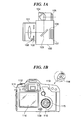
- FIG. 1A is a schematic cross-sectional view, taken along an optical axis, of a digital camera as an electronic apparatus according to the embodiment of the present invention
- FIG. 1B is a view of the appearance of the digital camera in FIG. 1A , as viewed from the rear of the same.
- object light having passed through a photographic lens 101 and a diaphragm 102 is reflected upward from a mirror 103 to be guided to an optical finder 105 via a pentagonal prism 104.
- a release button 114 (see FIG. 1B ) is fully pressed, a shooting operation is started, and the mirror 103 is retracted from an optical axis, whereby object light having passed through the photographic lens 101 and the diaphragm 102 forms an image on an image pickup device 107 via a shutter curtain 106.
- a gyro sensor 108 detects an amount of shake that occurs during shooting.
- the digital camera 100 has a power switch 109, an electronic dial 110, a live view button 111, a moving image start button 112, an AF instruction button 113, and a determination button 115, arranged on the rear surface thereof. Further, a display section 116 implemented e.g. by a TFT, an LCD, or an organic EL is disposed on the rear surface of the digital camera 100.
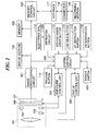
- FIG. 2 is a block diagram of a control system of the digital camera 100.
- an image processing circuit 201 carries out a predetermined pixel interpolation process and a predetermined color conversion process on image data output from the image pickup device 107 or image data output from a memory control circuit 202. Further, the image processing circuit 201 carries out a predetermined computation process using image data obtained by shooting, and a system control circuit 200 carries out an automatic focusing (AF) process, an automatic exposure (AE) process, and an automatic white balancing process (AWB) based on results of the predetermined computation process.
- AF automatic focusing
- AE automatic exposure
- AVB automatic white balancing process
- the memory control circuit 202 controls the image processing circuit 201 and a memory 205. Image data output from the image pickup device 107 is written into the memory 205 via the image processing circuit 201 and the memory control circuit 202, or only via the memory control circuit 202.
- the memory 205 stores still image data and moving image data obtained by shooting.
- An exposure control unit 203 controls the diaphragm 102 and the shutter curtain 106, and a focus control unit 204 controls a focusing operation by the photographic lens 101.
- the system control circuit 200 includes a CPU (central processing unit), a ROM (read only memory), and a RAM (random access memory), and controls the overall operation of the digital camera 100.
- the power switch 109 is a button for giving an instruction for switching on or off the power of the digital camera 100.
- the electronic dial 110 is operated to set a shutter speed, a diaphragm value, an ISO sensitivity, etc., or to select an item on a menu screen displayed on the display section 116.
- the electronic dial 110 corresponds to an example of a rotational operation member of the present invention.
- the determination button 115 is pressed to determine a selection performed using the electronic dial 110.
- the live view button 111 is pressed to give an instruction for starting live view shooting.
- the moving image start button 112 is pressed to give an instruction for starting moving image shooting in a live view shooting state of the digital camera 100.
- the AF instruction button 113 is pressed to give an instruction for starting an operation e.g. for the AF process, the AE process, and the AWB process.
- the release button 114 is half pressed to give an instruction for starting the operation e.g. for the AF process, the AE process, and the AWB process. Further, the release button 114 is fully pressed to give an instruction for starting an exposure process for writing image data from the image pickup device 107 into the memory 205 via the memory control circuit 202 and a recording process for writing the image data in a recording section 120.
- An interface 117 connects between the recording section 120, such as a memory card or a hard disk, and the digital camera 100 via a connector 118.
- FIG. 3A is a cross-sectional view of the electronic dial 110, taken along the axis thereof
- FIG. 3B is an enlarged view of a "b" portion appearing in FIG. 3A
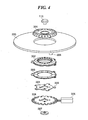
- FIG. 4 is an exploded perspective view of the electronic dial 110.
- FIG. 5A is a view of a printed circuit board 303 of the electronic dial 110, as viewed from the front of the electronic dial 110
- FIG. 5B is a view of the printed circuit board 303 as viewed from the rear of the same.
- FIG. 5C is a view showing the relationship between the printed circuit board 303 of the electronic dial 110 and a rotary plate 304 of the same
- FIG. 5D is a view showing another example of the relationship between the printed circuit board 303 and the rotary plate 304.
- the electronic dial 110 comprises a rotational operation member 301, a rotation support member 302, the printed circuit board 303, the rotary plate 304, a lock switch 305, and a lock plate 306.
- the rotation support member 302 is rigidly secured to an exterior cover 300, and the rotational operation member 301 is rotatably supported by the rotation support member 302.
- the rotational operation member 301 accommodates a click generating member 308 formed by a ball or a spring.
- the click generating member 308 is brought into engagement with a click plate formed into a wavy shape such that it extends circumferentially along the inner periphery of the rotation support member 302, to thereby give a click feeling to a user.
- the determination button 115 is fitted into the central part of the rotational operation member 301 such that it can be depressed. A depression of the determination button 115 is detected by a button operation detecting member 307.
- the printed circuit board 303 is rigidly secured to the rear surface (lower surface as viewed in FIGS. 3A, 3B , and 4 ) of the rotation support member 302.
- a detection electrode group A 400 on the front surface (upper surface as viewed in FIGS. 3A, 3B , and 4 ) of the printed circuit board 303, there is formed a detection electrode group A 400
- a detection electrode group B 401 on the rear surface of the printed circuit board 303.
- Each detection electrode of the detection electrode group A 400 and the detection electrode group B 401 is of an electrostatic capacity type, and a change in electrostatic capacity in each of the detection electrode group A 400 and the detection electrode group B 401 is detected by a detection circuit 206.
- the rear surface of the printed circuit board 303 has an inner periphery thereof formed with a ground electrode 402.
- the ground electrode 402 is formed in a manner flush with the detection electrode group B 401.
- the rotary plate 304 is rigidly secured to the rotational operation member 301 in a manner opposed to the ground electrode 402 on the rear surface of the printed circuit board 303 in a direction of the rotational axis of the rotary plate 304.
- the rotary plate 304 has a plurality of detecting portions 309 circumferentially formed at substantially equally-spaced intervals and extending outward from an outer periphery thereof such that they are each opposed to any detection electrode included in the detection electrode group B 401 in the direction of the rotational axis of the rotary plate 304.
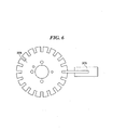
- the lock plate 306 cooperates with the lock switch 305 to form a lock mechanism for restricting rotation of the rotational operation member 301.
- the lock mechanism will be described hereinafter in detail with reference to FIG. 6 .
- the detection electrode group A 400 is used to detect a touch operation by a user's finger on the surface of the rotational operation member 301. More specifically, when a finger approaches the surface of the rotational operation member 301, there occurs a change in electrostatic capacity of a detection electrode included in the detection electrode group A 400, and the change is detected by the detection circuit 206. Then, the system control circuit 200 determines based on a result of the detection by the detection circuit 206 that the surface of the rotational operation member 301 has been touch-operated.
- the detection electrode group B 401 is used for detecting the turning operation of the detecting portions 309 of the rotary plate 304.
- the rotary plate 304 is axially opposed to the ground electrode 402 of the printed circuit board 303 and electrostatically coupled to the same.
- the detection electrode group B 401 is composed of detection electrodes of four types B1 to B4. For this reason, when the detection electrodes of one of the four types B1 to B4 of the detection electrode group B 401 are brought into axially facing relation to the detecting portions 309 of the rotary plate 304, they are electrostatically coupled to the ground electrode 402 of the printed circuit board 303 via the rotary plate 304.
- the detection circuit 206 detects changes in electrostatic capacity in the detection electrode types B1 and B2. Then, the system control circuit 200 determines, based on a detection result from the detection circuit 206, that the rotational operation member 301 is turn-operated in a direction from the detection electrode type B1 to the detection electrode type B2 (clockwise as viewed in FIG. 5B ).
- the detection circuit 206 detects that all the detection electrodes of the detection electrode group A 400 are identical in potential, which prevents detection in a change in electrostatic capacity of each detection electrode included in the detection electrode group A 400, so that the system control circuit 200 can only determine whether or not the rotational operation member 301 has been touch-operated.
- the rotational operation member 301 and the rotation support member 302 are formed of a nonconductive material, such as a ceramic material or a resin material, so as to detect a circumferential touch position on the rotational operation member 301 and secure the same function as that of the turning operation of the conventional electronic dial.
- the detection electrode group A 400 is composed of detection electrodes of five types A1 to A5.
- the detection electrodes of five types A1 to A5 are circumferentially sequentially arranged at equal-spaced intervals in order from A1 to A5 within a range of 180 degrees.
- the detection electrode group A 400 has two repeated arrangements of the detection electrodes of the five types A1 to A5 in a range of 360 degrees. Note that the detection electrodes A1 to A5 correspond to an example of first detection electrodes of the present invention.
- the detection electrode group A 400 is formed as a single electrode assembly, and therefore it is possible to reduce wiring in comparison with a case where a plurality of independent electrodes are respectively formed, and reduce load applied to the system control circuit 200.
- the detection electrode group B 401 formed on the rear surface of the printed circuit board 303 is disposed such that the detection electrodes of the four types B1 to B4 are circumferentially sequentially arranged at equal-spaced intervals in order from B1 to B4 in a range of 72 degrees.
- the detection electrode group B 401 has five repeated arrangements of the detections electrodes of the four types B1 to B4. Therefore, the detection electrodes of each of the types B1 to B4 are disposed at every 72 degrees.
- the number of the detection electrodes included in the detection electrode group B 401 is made equal to the number (twenty in the present embodiment) of clicks which should occur per one rotation of the rotational operation member 301, and with this arrangement, a turn of the rotary plate 304 is detected in association with occurrence of a click feeling given by a turning operation of the rotational operation member 301.
- the detection electrodes B1 to B4 correspond to an example of second detection electrodes of the present invention.
- the detection electrode group B 401 is formed as a single electrode assembly, and therefore it is possible to reduce wiring in comparison with a case where a plurality of independent electrodes are respectively formed, and reduce load applied to the system control circuit 200.
- each of the detecting portions 309 of the rotary plate 304 has substantially the same shape as one detection electrode as a component of the detection electrode group B 401.
- the detecting portions 309 are formed in number corresponding to the number of detection electrodes of each of the four types B1 to B4 arranged in the range of 360 degrees (i.e. five in the present embodiment), and the detecting portions 309 are disposed such they are axially opposed to the detection electrodes of one of the four types B1 to B4 (the detection electrode type B4 in FIG. 5C ).
- each of the detecting portions 309 may be disposed in a manner axially opposed to a plurality of detection electrode types. More specifically, as shown in FIG. 5D , the detecting portions 309 may be shaped such that they can be axially opposed to the detection electrode types B1, B2, and B3 out of the four detection electrode types B1 to B4.
- the ground electrode 402 is formed along the entire circumference of the printed circuit board 303, the entire surface of the rotary plate 304 is axially opposed to the ground electrode 402 irrespective of the rotational phase of the rotary plate 304, so that detection sensitivity can be improved.
- the lock mechanism is configured to be operable in a case where a setting for inputting a turning operation by touch operation is designated by the user, to prevent an inadvertent turning operation of the rotational operation member 301 from causing the detection electrodes A 400 and B 401 to perform simultaneous detection of the operation.
- the lock plate 306 has an outer periphery thereof circumferentially formed with protrusions and recesses, and is rigidly secured to the rotational operation member 301 from the rear-surface side of the rotary plate 304, together with the rotary plate 304.
- the lock switch 305 is formed e.g. by a solenoid.
- the system control circuit 200 instructs the lock switch 305 to come into engagement with a recess of the outer periphery of the lock plate 306 by projecting a plunger, to thereby restrict rotation of the rotational operation member 301.
- the construction of the lock mechanism is not particularly limited, but the lock mechanism can have any suitable construction insofar as it can restrict rotation of the rotational operation member 301 when the setting for inputting a turning operation by touch operation is designated by the user.
- the shooting control process in FIG. 7 is executed e.g. by the CPU of the system control circuit 200 by loading an associated program stored e.g. in the ROM into the RAM.
- the system control circuit 200 starts a moving image shooting mode in a step S100, and the system control circuit 200 proceeds to a step S101.
- the system control circuit 200 determines whether or not the setting of "input by touch-operating the electronic dial 110" has been selected by user operation. If the option "input by touch-operating the electronic dial 110" has been selected, the process proceeds to a step S105, whereas if not, the system control circuit 200 proceeds to a step S102.
- the option "input by touch-operating the electronic dial 110" may be selected by user operation from a menu screen displayed on the display section 116, or alternatively, a dedicated operation member may be provided for the selection by user operation.
- step S102 when the release button 114 is operated, the system control circuit 200 starts moving image shooting, and then the system control circuit 200 proceeds to a step S103.
- the system control circuit 200 causes the detection circuit 206 to detect a turning operation of the rotational operation member 301, based on a change in electrostatic capacity of each of the detection electrodes constituting the detection electrode group B 401, thereby determining that a predetermined setting associated with the turning operation has been selected, and then proceeds to a step S104.
- the system control circuit 200 determines whether or not the power switch 109 has been turned off. If the power switch 109 has been turned off, the system control circuit 200 stops shooting operation and terminates the present process. On the other hand, if the power switch 109 has not been turned off, the process returns to the step S100, and the moving image shooting is continued in the moving image shooting mode.
- step S105 the system control circuit 200 causes the lock switch 305 to project the plunger to restrict rotation of the rotational operation member 301, and then the system control circuit 200 proceeds to a step S106.
- step S106 when the release button 114 is operated, the system control circuit 200 starts moving image shooting, and then the system control circuit 200 proceeds to a step S107.
- the system control circuit 200 causes the detection circuit 206 to detect a touch operation onto the rotational operation member 301, based on a change in electrostatic capacity of each of the detection electrodes constituting the detection electrode group A 401, thereby determining that a predetermined setting associated with the touch operation has been selected, and then proceeds to the step S104.
- the electronic dial 110 is provided with the click mechanism, it is possible to change respective settings associated with the diaphragm value, the shutter speed, the ISO sensitivity, and so forth, by touch-operating the rotational operation member 301 during moving image shooting, without generating a click noise.
- recording of click noises during moving image shooting can be prevented.
- the detection electrode groups A 400 and B 401 are both of an electrostatic capacity type, and a change in the electrostatic capacity in the detection electrode group A 400 and the detection electrode group B 401 is detected by the detection circuit 206. Therefore, it is possible to improve the durability of the electronic dial 110 in comparison with an electronic dial using a contact piece.
- the rotational operation member 301 may be touch-operated during still image shooting so as to change the settings.
Landscapes
- Engineering & Computer Science (AREA)
- Physics & Mathematics (AREA)
- General Physics & Mathematics (AREA)
- General Engineering & Computer Science (AREA)
- Theoretical Computer Science (AREA)
- Human Computer Interaction (AREA)
- Rotary Switch, Piano Key Switch, And Lever Switch (AREA)
- Camera Bodies And Camera Details Or Accessories (AREA)
- Studio Devices (AREA)
Applications Claiming Priority (1)
| Application Number | Priority Date | Filing Date | Title |
|---|---|---|---|
| JP2010275772A JP5677062B2 (ja) | 2010-12-10 | 2010-12-10 | 電子機器 |
Publications (2)
| Publication Number | Publication Date |
|---|---|
| EP2463712A1 EP2463712A1 (en) | 2012-06-13 |
| EP2463712B1 true EP2463712B1 (en) | 2015-03-25 |
Family
ID=45063049
Family Applications (1)
| Application Number | Title | Priority Date | Filing Date |
|---|---|---|---|
| EP11191992.4A Active EP2463712B1 (en) | 2010-12-10 | 2011-12-05 | Electronic apparatus that detects different kinds of operations on rotational operation member |
Country Status (5)
| Country | Link |
|---|---|
| US (1) | US8976047B2 (enExample) |
| EP (1) | EP2463712B1 (enExample) |
| JP (1) | JP5677062B2 (enExample) |
| KR (1) | KR101447460B1 (enExample) |
| CN (1) | CN102540630B (enExample) |
Families Citing this family (11)
| Publication number | Priority date | Publication date | Assignee | Title |
|---|---|---|---|---|
| US9534933B2 (en) * | 2014-01-14 | 2017-01-03 | Panasonic Automotive Systems Company Of America, Division Of Panasonic Corporation Of North America | Capacitive encoder |
| EP3160126A4 (en) * | 2014-06-17 | 2018-04-25 | Sony Corporation | Imaging system, imaging device, information processing device and method, and program |
| JP6444350B2 (ja) * | 2016-09-27 | 2018-12-26 | キヤノン株式会社 | 表示制御装置およびその制御方法 |
| CN109863740B (zh) * | 2016-11-15 | 2020-11-13 | 富士胶片株式会社 | 相机、相机的设定方法及记录介质 |
| US10943869B2 (en) | 2017-06-09 | 2021-03-09 | Apple Inc. | High density interconnection using fanout interposer chiplet |
| US10742217B2 (en) | 2018-04-12 | 2020-08-11 | Apple Inc. | Systems and methods for implementing a scalable system |
| JP7219615B2 (ja) * | 2018-12-28 | 2023-02-08 | 株式会社ジャパンディスプレイ | 操作支援装置 |
| DE102019114429A1 (de) * | 2019-05-29 | 2020-12-03 | Preh Gmbh | Eingabevorrichtung mit beweglicher Handhabe auf kapazitiver Detektionsfläche und kapazitiven Koppeleinrichtungen |
| KR102188956B1 (ko) * | 2020-04-24 | 2020-12-09 | 방윤철 | 무전원 반자동 회전형 촬영장치 |
| CN112924270B (zh) * | 2021-01-27 | 2023-07-07 | 上海德岂智能科技有限公司 | 一种pcb电路板的检测装置 |
| US12196583B2 (en) * | 2023-02-06 | 2025-01-14 | Canon Kabushiki Kaisha | Rotational operation device and electronic apparatus having the same |
Family Cites Families (26)
| Publication number | Priority date | Publication date | Assignee | Title |
|---|---|---|---|---|
| US5005033A (en) | 1988-08-01 | 1991-04-02 | Olympus Optical Company, Ltd. | Photographing data setting apparatus for camera |
| JPH11109469A (ja) | 1997-10-03 | 1999-04-23 | Asahi Optical Co Ltd | カメラのダブルダイヤル機構 |
| US6154210A (en) * | 1998-11-25 | 2000-11-28 | Flashpoint Technology, Inc. | Method and system for implementing button interface compatibility in touch-screen equipped digital imaging device |
| JP2000357049A (ja) * | 1999-06-16 | 2000-12-26 | Alps Electric Co Ltd | 回転入力装置 |
| JP2002258375A (ja) * | 2001-03-02 | 2002-09-11 | Kyocera Corp | カメラのダイヤル用スイッチ装置 |
| JP4915491B2 (ja) * | 2001-08-03 | 2012-04-11 | 株式会社ニコン | 制御装置及びカメラ |
| EP1486860A4 (en) * | 2002-03-05 | 2010-06-30 | Sony Ericsson Mobile Comm Jp | Image processing device, image processing program and image processing method |
| US7024947B2 (en) * | 2002-03-07 | 2006-04-11 | Alps Electric Co., Ltd. | Detection device including circuit component |
| JP2004327218A (ja) | 2003-04-24 | 2004-11-18 | Sony Corp | クリック付きセレクト機構および電子機器 |
| JP2005112027A (ja) * | 2003-10-03 | 2005-04-28 | Matsushita Electric Ind Co Ltd | 入力スイッチとそれを用いた自動車および映像撮影装置 |
| JP4279121B2 (ja) * | 2003-11-13 | 2009-06-17 | アルプス電気株式会社 | 回転式入力装置 |
| JP3979384B2 (ja) * | 2003-12-22 | 2007-09-19 | ソニー株式会社 | 撮像手段を有する電子機器および記録再生手段を有する撮像装置 |
| JP4624752B2 (ja) * | 2004-09-28 | 2011-02-02 | 京セラ株式会社 | 回転装置 |
| JP2006119519A (ja) * | 2004-10-25 | 2006-05-11 | Canon Inc | カメラの情報設定装置 |
| JP4306592B2 (ja) * | 2004-11-15 | 2009-08-05 | ソニー株式会社 | 再生装置、表示制御方法 |
| JP2006154051A (ja) * | 2004-11-26 | 2006-06-15 | Fuji Photo Film Co Ltd | カメラ |
| JP4751715B2 (ja) | 2005-12-22 | 2011-08-17 | 株式会社リコー | 撮像装置 |
| JP2007214774A (ja) * | 2006-02-08 | 2007-08-23 | Canon Inc | 撮像装置 |
| CN101449230B (zh) * | 2006-05-30 | 2014-12-03 | 日本电气株式会社 | 输入装置 |
| JP2008078045A (ja) * | 2006-09-22 | 2008-04-03 | Olympus Corp | ダイヤルスイッチ、電子機器およびカメラ |
| JP2008165118A (ja) * | 2007-01-05 | 2008-07-17 | Nikon Corp | 設定装置、設定装置を備えた電子機器、及び設定装置を備えたデジタルカメラ |
| JP2008304632A (ja) * | 2007-06-06 | 2008-12-18 | Casio Comput Co Ltd | カメラ及びカメラのレンズ鏡筒制御方法 |
| KR20090006807A (ko) * | 2007-07-11 | 2009-01-15 | 오의진 | 손가락의 동작감지를 이용한 데이터입력장치 및 이를이용한 입력변환방법 |
| JP2009093379A (ja) * | 2007-10-05 | 2009-04-30 | Sharp Corp | 回転型セレクター、および回転型セレクターの制御方法 |
| JP4990811B2 (ja) * | 2008-02-08 | 2012-08-01 | ホシデン株式会社 | 回転スイッチ |
| JP4360442B2 (ja) | 2008-02-18 | 2009-11-11 | オムロン株式会社 | 入力装置及びこれを用いた電子機器 |
-
2010
- 2010-12-10 JP JP2010275772A patent/JP5677062B2/ja active Active
-
2011
- 2011-12-02 US US13/310,234 patent/US8976047B2/en active Active
- 2011-12-05 EP EP11191992.4A patent/EP2463712B1/en active Active
- 2011-12-09 KR KR1020110131482A patent/KR101447460B1/ko not_active Expired - Fee Related
- 2011-12-09 CN CN201110415585.XA patent/CN102540630B/zh active Active
Also Published As
| Publication number | Publication date |
|---|---|
| JP5677062B2 (ja) | 2015-02-25 |
| KR101447460B1 (ko) | 2014-10-07 |
| KR20120065253A (ko) | 2012-06-20 |
| JP2012123304A (ja) | 2012-06-28 |
| CN102540630A (zh) | 2012-07-04 |
| US8976047B2 (en) | 2015-03-10 |
| US20120146818A1 (en) | 2012-06-14 |
| CN102540630B (zh) | 2014-07-30 |
| EP2463712A1 (en) | 2012-06-13 |
Similar Documents
| Publication | Publication Date | Title |
|---|---|---|
| EP2463712B1 (en) | Electronic apparatus that detects different kinds of operations on rotational operation member | |
| US12464250B2 (en) | Camera | |
| US12003847B2 (en) | Camera, setting method of camera, and setting program of camera | |
| US9251977B2 (en) | Electronic apparatus | |
| US10520794B2 (en) | Camera, setting method of camera, and setting program of camera | |
| US12035022B2 (en) | Information input device allowing tilt operation of multi-directional input | |
| JP6542485B2 (ja) | カメラ、カメラの設定方法、及び、カメラの設定プログラム | |
| US20120139880A1 (en) | Information processing apparatus adapted to operation using a plurality of operation elements, method of controlling the information processing apparatus, and storage medium | |
| JP2021047360A (ja) | 撮像装置 | |
| JP7760270B2 (ja) | 電子機器 | |
| US11605513B2 (en) | Information input device and image capture device | |
| JP2015146228A (ja) | 電子機器 | |
| JP2020101728A (ja) | 電子機器 | |
| JPWO2018020948A1 (ja) | カメラ、カメラの設定方法、及び、カメラの設定プログラム | |
| JP2009146668A (ja) | 電子機器 | |
| JP4154420B2 (ja) | カメラ | |
| JP2020101725A (ja) | 電子機器 | |
| JP2019061136A (ja) | 電子機器及び撮像装置 | |
| JP2020101727A (ja) | 電子機器 | |
| JP2018106190A (ja) | 撮像装置の操作部材 | |
| JPH0980577A (ja) | 情報設定装置 |
Legal Events
| Date | Code | Title | Description |
|---|---|---|---|
| PUAI | Public reference made under article 153(3) epc to a published international application that has entered the european phase |
Free format text: ORIGINAL CODE: 0009012 |
|
| AK | Designated contracting states |
Kind code of ref document: A1 Designated state(s): AL AT BE BG CH CY CZ DE DK EE ES FI FR GB GR HR HU IE IS IT LI LT LU LV MC MK MT NL NO PL PT RO RS SE SI SK SM TR |
|
| AX | Request for extension of the european patent |
Extension state: BA ME |
|
| 17P | Request for examination filed |
Effective date: 20121213 |
|
| RIC1 | Information provided on ipc code assigned before grant |
Ipc: G06F 3/0362 20130101ALI20140828BHEP Ipc: H01H 25/06 20060101ALI20140828BHEP Ipc: G03B 17/18 20060101AFI20140828BHEP Ipc: G03B 17/02 20060101ALI20140828BHEP |
|
| GRAJ | Information related to disapproval of communication of intention to grant by the applicant or resumption of examination proceedings by the epo deleted |
Free format text: ORIGINAL CODE: EPIDOSDIGR1 |
|
| GRAP | Despatch of communication of intention to grant a patent |
Free format text: ORIGINAL CODE: EPIDOSNIGR1 |
|
| INTG | Intention to grant announced |
Effective date: 20141013 |
|
| RIN1 | Information on inventor provided before grant (corrected) |
Inventor name: DEGAWA, TAKAMASA |
|
| GRAS | Grant fee paid |
Free format text: ORIGINAL CODE: EPIDOSNIGR3 |
|
| GRAA | (expected) grant |
Free format text: ORIGINAL CODE: 0009210 |
|
| AK | Designated contracting states |
Kind code of ref document: B1 Designated state(s): AL AT BE BG CH CY CZ DE DK EE ES FI FR GB GR HR HU IE IS IT LI LT LU LV MC MK MT NL NO PL PT RO RS SE SI SK SM TR |
|
| REG | Reference to a national code |
Ref country code: GB Ref legal event code: FG4D |
|
| REG | Reference to a national code |
Ref country code: CH Ref legal event code: EP |
|
| REG | Reference to a national code |
Ref country code: IE Ref legal event code: FG4D |
|
| REG | Reference to a national code |
Ref country code: DE Ref legal event code: R096 Ref document number: 602011014982 Country of ref document: DE Effective date: 20150507 |
|
| REG | Reference to a national code |
Ref country code: AT Ref legal event code: REF Ref document number: 718208 Country of ref document: AT Kind code of ref document: T Effective date: 20150515 |
|
| PG25 | Lapsed in a contracting state [announced via postgrant information from national office to epo] |
Ref country code: LT Free format text: LAPSE BECAUSE OF FAILURE TO SUBMIT A TRANSLATION OF THE DESCRIPTION OR TO PAY THE FEE WITHIN THE PRESCRIBED TIME-LIMIT Effective date: 20150325 Ref country code: HR Free format text: LAPSE BECAUSE OF FAILURE TO SUBMIT A TRANSLATION OF THE DESCRIPTION OR TO PAY THE FEE WITHIN THE PRESCRIBED TIME-LIMIT Effective date: 20150325 Ref country code: SE Free format text: LAPSE BECAUSE OF FAILURE TO SUBMIT A TRANSLATION OF THE DESCRIPTION OR TO PAY THE FEE WITHIN THE PRESCRIBED TIME-LIMIT Effective date: 20150325 Ref country code: FI Free format text: LAPSE BECAUSE OF FAILURE TO SUBMIT A TRANSLATION OF THE DESCRIPTION OR TO PAY THE FEE WITHIN THE PRESCRIBED TIME-LIMIT Effective date: 20150325 |
|
| REG | Reference to a national code |
Ref country code: AT Ref legal event code: MK05 Ref document number: 718208 Country of ref document: AT Kind code of ref document: T Effective date: 20150325 |
|
| REG | Reference to a national code |
Ref country code: LT Ref legal event code: MG4D |
|
| PG25 | Lapsed in a contracting state [announced via postgrant information from national office to epo] |
Ref country code: LV Free format text: LAPSE BECAUSE OF FAILURE TO SUBMIT A TRANSLATION OF THE DESCRIPTION OR TO PAY THE FEE WITHIN THE PRESCRIBED TIME-LIMIT Effective date: 20150325 Ref country code: GR Free format text: LAPSE BECAUSE OF FAILURE TO SUBMIT A TRANSLATION OF THE DESCRIPTION OR TO PAY THE FEE WITHIN THE PRESCRIBED TIME-LIMIT Effective date: 20150626 Ref country code: RS Free format text: LAPSE BECAUSE OF FAILURE TO SUBMIT A TRANSLATION OF THE DESCRIPTION OR TO PAY THE FEE WITHIN THE PRESCRIBED TIME-LIMIT Effective date: 20150325 |
|
| PG25 | Lapsed in a contracting state [announced via postgrant information from national office to epo] |
Ref country code: NL Free format text: LAPSE BECAUSE OF FAILURE TO SUBMIT A TRANSLATION OF THE DESCRIPTION OR TO PAY THE FEE WITHIN THE PRESCRIBED TIME-LIMIT Effective date: 20150325 |
|
| PG25 | Lapsed in a contracting state [announced via postgrant information from national office to epo] |
Ref country code: RO Free format text: LAPSE BECAUSE OF FAILURE TO SUBMIT A TRANSLATION OF THE DESCRIPTION OR TO PAY THE FEE WITHIN THE PRESCRIBED TIME-LIMIT Effective date: 20150325 Ref country code: ES Free format text: LAPSE BECAUSE OF FAILURE TO SUBMIT A TRANSLATION OF THE DESCRIPTION OR TO PAY THE FEE WITHIN THE PRESCRIBED TIME-LIMIT Effective date: 20150325 Ref country code: PT Free format text: LAPSE BECAUSE OF FAILURE TO SUBMIT A TRANSLATION OF THE DESCRIPTION OR TO PAY THE FEE WITHIN THE PRESCRIBED TIME-LIMIT Effective date: 20150727 Ref country code: EE Free format text: LAPSE BECAUSE OF FAILURE TO SUBMIT A TRANSLATION OF THE DESCRIPTION OR TO PAY THE FEE WITHIN THE PRESCRIBED TIME-LIMIT Effective date: 20150325 Ref country code: CZ Free format text: LAPSE BECAUSE OF FAILURE TO SUBMIT A TRANSLATION OF THE DESCRIPTION OR TO PAY THE FEE WITHIN THE PRESCRIBED TIME-LIMIT Effective date: 20150325 Ref country code: SK Free format text: LAPSE BECAUSE OF FAILURE TO SUBMIT A TRANSLATION OF THE DESCRIPTION OR TO PAY THE FEE WITHIN THE PRESCRIBED TIME-LIMIT Effective date: 20150325 |
|
| PG25 | Lapsed in a contracting state [announced via postgrant information from national office to epo] |
Ref country code: PL Free format text: LAPSE BECAUSE OF FAILURE TO SUBMIT A TRANSLATION OF THE DESCRIPTION OR TO PAY THE FEE WITHIN THE PRESCRIBED TIME-LIMIT Effective date: 20150325 Ref country code: AT Free format text: LAPSE BECAUSE OF FAILURE TO SUBMIT A TRANSLATION OF THE DESCRIPTION OR TO PAY THE FEE WITHIN THE PRESCRIBED TIME-LIMIT Effective date: 20150325 Ref country code: IS Free format text: LAPSE BECAUSE OF FAILURE TO SUBMIT A TRANSLATION OF THE DESCRIPTION OR TO PAY THE FEE WITHIN THE PRESCRIBED TIME-LIMIT Effective date: 20150725 |
|
| REG | Reference to a national code |
Ref country code: DE Ref legal event code: R097 Ref document number: 602011014982 Country of ref document: DE |
|
| PG25 | Lapsed in a contracting state [announced via postgrant information from national office to epo] |
Ref country code: DK Free format text: LAPSE BECAUSE OF FAILURE TO SUBMIT A TRANSLATION OF THE DESCRIPTION OR TO PAY THE FEE WITHIN THE PRESCRIBED TIME-LIMIT Effective date: 20150325 |
|
| PLBE | No opposition filed within time limit |
Free format text: ORIGINAL CODE: 0009261 |
|
| STAA | Information on the status of an ep patent application or granted ep patent |
Free format text: STATUS: NO OPPOSITION FILED WITHIN TIME LIMIT |
|
| 26N | No opposition filed |
Effective date: 20160105 |
|
| PG25 | Lapsed in a contracting state [announced via postgrant information from national office to epo] |
Ref country code: IT Free format text: LAPSE BECAUSE OF FAILURE TO SUBMIT A TRANSLATION OF THE DESCRIPTION OR TO PAY THE FEE WITHIN THE PRESCRIBED TIME-LIMIT Effective date: 20150325 |
|
| PG25 | Lapsed in a contracting state [announced via postgrant information from national office to epo] |
Ref country code: SI Free format text: LAPSE BECAUSE OF FAILURE TO SUBMIT A TRANSLATION OF THE DESCRIPTION OR TO PAY THE FEE WITHIN THE PRESCRIBED TIME-LIMIT Effective date: 20150325 Ref country code: BE Free format text: LAPSE BECAUSE OF NON-PAYMENT OF DUE FEES Effective date: 20151231 |
|
| PG25 | Lapsed in a contracting state [announced via postgrant information from national office to epo] |
Ref country code: LU Free format text: LAPSE BECAUSE OF FAILURE TO SUBMIT A TRANSLATION OF THE DESCRIPTION OR TO PAY THE FEE WITHIN THE PRESCRIBED TIME-LIMIT Effective date: 20151205 Ref country code: MC Free format text: LAPSE BECAUSE OF FAILURE TO SUBMIT A TRANSLATION OF THE DESCRIPTION OR TO PAY THE FEE WITHIN THE PRESCRIBED TIME-LIMIT Effective date: 20150325 |
|
| REG | Reference to a national code |
Ref country code: CH Ref legal event code: PL |
|
| PG25 | Lapsed in a contracting state [announced via postgrant information from national office to epo] |
Ref country code: BE Free format text: LAPSE BECAUSE OF FAILURE TO SUBMIT A TRANSLATION OF THE DESCRIPTION OR TO PAY THE FEE WITHIN THE PRESCRIBED TIME-LIMIT Effective date: 20150325 |
|
| REG | Reference to a national code |
Ref country code: IE Ref legal event code: MM4A |
|
| PG25 | Lapsed in a contracting state [announced via postgrant information from national office to epo] |
Ref country code: IE Free format text: LAPSE BECAUSE OF NON-PAYMENT OF DUE FEES Effective date: 20151205 Ref country code: CH Free format text: LAPSE BECAUSE OF NON-PAYMENT OF DUE FEES Effective date: 20151231 Ref country code: LI Free format text: LAPSE BECAUSE OF NON-PAYMENT OF DUE FEES Effective date: 20151231 |
|
| REG | Reference to a national code |
Ref country code: FR Ref legal event code: PLFP Year of fee payment: 6 |
|
| PG25 | Lapsed in a contracting state [announced via postgrant information from national office to epo] |
Ref country code: SM Free format text: LAPSE BECAUSE OF FAILURE TO SUBMIT A TRANSLATION OF THE DESCRIPTION OR TO PAY THE FEE WITHIN THE PRESCRIBED TIME-LIMIT Effective date: 20150325 Ref country code: HU Free format text: LAPSE BECAUSE OF FAILURE TO SUBMIT A TRANSLATION OF THE DESCRIPTION OR TO PAY THE FEE WITHIN THE PRESCRIBED TIME-LIMIT; INVALID AB INITIO Effective date: 20111205 Ref country code: BG Free format text: LAPSE BECAUSE OF FAILURE TO SUBMIT A TRANSLATION OF THE DESCRIPTION OR TO PAY THE FEE WITHIN THE PRESCRIBED TIME-LIMIT Effective date: 20150325 Ref country code: NO Free format text: LAPSE BECAUSE OF FAILURE TO SUBMIT A TRANSLATION OF THE DESCRIPTION OR TO PAY THE FEE WITHIN THE PRESCRIBED TIME-LIMIT Effective date: 20150625 |
|
| PG25 | Lapsed in a contracting state [announced via postgrant information from national office to epo] |
Ref country code: CY Free format text: LAPSE BECAUSE OF FAILURE TO SUBMIT A TRANSLATION OF THE DESCRIPTION OR TO PAY THE FEE WITHIN THE PRESCRIBED TIME-LIMIT Effective date: 20150325 |
|
| PG25 | Lapsed in a contracting state [announced via postgrant information from national office to epo] |
Ref country code: MT Free format text: LAPSE BECAUSE OF FAILURE TO SUBMIT A TRANSLATION OF THE DESCRIPTION OR TO PAY THE FEE WITHIN THE PRESCRIBED TIME-LIMIT Effective date: 20150325 Ref country code: TR Free format text: LAPSE BECAUSE OF FAILURE TO SUBMIT A TRANSLATION OF THE DESCRIPTION OR TO PAY THE FEE WITHIN THE PRESCRIBED TIME-LIMIT Effective date: 20150325 |
|
| REG | Reference to a national code |
Ref country code: FR Ref legal event code: PLFP Year of fee payment: 7 |
|
| PG25 | Lapsed in a contracting state [announced via postgrant information from national office to epo] |
Ref country code: MK Free format text: LAPSE BECAUSE OF FAILURE TO SUBMIT A TRANSLATION OF THE DESCRIPTION OR TO PAY THE FEE WITHIN THE PRESCRIBED TIME-LIMIT Effective date: 20150325 |
|
| PG25 | Lapsed in a contracting state [announced via postgrant information from national office to epo] |
Ref country code: AL Free format text: LAPSE BECAUSE OF FAILURE TO SUBMIT A TRANSLATION OF THE DESCRIPTION OR TO PAY THE FEE WITHIN THE PRESCRIBED TIME-LIMIT Effective date: 20150325 |
|
| PGFP | Annual fee paid to national office [announced via postgrant information from national office to epo] |
Ref country code: GB Payment date: 20201021 Year of fee payment: 10 Ref country code: FR Payment date: 20201021 Year of fee payment: 10 |
|
| GBPC | Gb: european patent ceased through non-payment of renewal fee |
Effective date: 20211205 |
|
| PG25 | Lapsed in a contracting state [announced via postgrant information from national office to epo] |
Ref country code: GB Free format text: LAPSE BECAUSE OF NON-PAYMENT OF DUE FEES Effective date: 20211205 |
|
| PG25 | Lapsed in a contracting state [announced via postgrant information from national office to epo] |
Ref country code: FR Free format text: LAPSE BECAUSE OF NON-PAYMENT OF DUE FEES Effective date: 20211231 |
|
| PGFP | Annual fee paid to national office [announced via postgrant information from national office to epo] |
Ref country code: DE Payment date: 20241121 Year of fee payment: 14 |