EP2463221A2 - Garnschneidvorrichtung - Google Patents
Garnschneidvorrichtung Download PDFInfo
- Publication number
- EP2463221A2 EP2463221A2 EP11192558A EP11192558A EP2463221A2 EP 2463221 A2 EP2463221 A2 EP 2463221A2 EP 11192558 A EP11192558 A EP 11192558A EP 11192558 A EP11192558 A EP 11192558A EP 2463221 A2 EP2463221 A2 EP 2463221A2
- Authority
- EP
- European Patent Office
- Prior art keywords
- yarn
- yarns
- guide
- cutting apparatus
- disposed
- Prior art date
- Legal status (The legal status is an assumption and is not a legal conclusion. Google has not performed a legal analysis and makes no representation as to the accuracy of the status listed.)
- Granted
Links
- 238000005520 cutting process Methods 0.000 title claims abstract description 78
- 230000001105 regulatory effect Effects 0.000 claims abstract description 31
- 238000011144 upstream manufacturing Methods 0.000 claims abstract description 8
- 238000004804 winding Methods 0.000 description 15
- 238000009987 spinning Methods 0.000 description 14
- 238000010586 diagram Methods 0.000 description 7
- 230000009467 reduction Effects 0.000 description 5
- 230000000694 effects Effects 0.000 description 4
- 230000005484 gravity Effects 0.000 description 3
- 230000007257 malfunction Effects 0.000 description 3
- 239000002994 raw material Substances 0.000 description 3
- 238000001514 detection method Methods 0.000 description 2
- 238000005516 engineering process Methods 0.000 description 2
- 238000000034 method Methods 0.000 description 2
- 238000004519 manufacturing process Methods 0.000 description 1
- 239000000155 melt Substances 0.000 description 1
- 238000011084 recovery Methods 0.000 description 1
Images


Classifications
-
- B—PERFORMING OPERATIONS; TRANSPORTING
- B65—CONVEYING; PACKING; STORING; HANDLING THIN OR FILAMENTARY MATERIAL
- B65H—HANDLING THIN OR FILAMENTARY MATERIAL, e.g. SHEETS, WEBS, CABLES
- B65H54/00—Winding, coiling, or depositing filamentary material
- B65H54/86—Arrangements for taking-up waste material before or after winding or depositing
- B65H54/88—Arrangements for taking-up waste material before or after winding or depositing by means of pneumatic arrangements, e.g. suction guns
-
- B—PERFORMING OPERATIONS; TRANSPORTING
- B65—CONVEYING; PACKING; STORING; HANDLING THIN OR FILAMENTARY MATERIAL
- B65H—HANDLING THIN OR FILAMENTARY MATERIAL, e.g. SHEETS, WEBS, CABLES
- B65H54/00—Winding, coiling, or depositing filamentary material
- B65H54/70—Other constructional features of yarn-winding machines
- B65H54/71—Arrangements for severing filamentary materials
-
- B—PERFORMING OPERATIONS; TRANSPORTING
- B65—CONVEYING; PACKING; STORING; HANDLING THIN OR FILAMENTARY MATERIAL
- B65H—HANDLING THIN OR FILAMENTARY MATERIAL, e.g. SHEETS, WEBS, CABLES
- B65H57/00—Guides for filamentary materials; Supports therefor
- B65H57/16—Guides for filamentary materials; Supports therefor formed to maintain a plurality of filaments in spaced relation
-
- B—PERFORMING OPERATIONS; TRANSPORTING
- B65—CONVEYING; PACKING; STORING; HANDLING THIN OR FILAMENTARY MATERIAL
- B65H—HANDLING THIN OR FILAMENTARY MATERIAL, e.g. SHEETS, WEBS, CABLES
- B65H57/00—Guides for filamentary materials; Supports therefor
- B65H57/28—Reciprocating or oscillating guides
-
- B—PERFORMING OPERATIONS; TRANSPORTING
- B65—CONVEYING; PACKING; STORING; HANDLING THIN OR FILAMENTARY MATERIAL
- B65H—HANDLING THIN OR FILAMENTARY MATERIAL, e.g. SHEETS, WEBS, CABLES
- B65H2701/00—Handled material; Storage means
- B65H2701/30—Handled filamentary material
- B65H2701/31—Textiles threads or artificial strands of filaments
- B65H2701/313—Synthetic polymer threads
- B65H2701/3132—Synthetic polymer threads extruded from spinnerets
Definitions
- the present invention relates to a technology of a yarn cutting apparatus to cut yarns. More particularly, the present invention relates to a technology of a yarn cutting apparatus to cut yarns manufactured in a take-up winding facility.
- a yarn threading operation that is, to thread the filaments or the yarns onto corresponding rollers or guides.
- a recovery measure is to cut the yarns. This necessitates an additional yarn threading operation by the operator.
- the yarn threading operation which involves threading of a plurality of filaments and a plurality of yarns, is a manual operation by the operator and involves a considerable process step count. Accordingly, there has been a need for a take-up winding facility with improved workability of the yarn threading operation.
- the yarns are cut by a yarn cutting apparatus disposed further downstream than the spinning machine.
- the yarn cutting apparatus has a function to suck and discharge filaments continuously spun from the spinning machine.
- the operator uses a suction gun with which to suck and hold the filaments having been sucked by the yarn cutting apparatus, and carries out the yarn threading operation by manipulating the suction gun holding the filaments.
- the yarn threading operation in particular associated with the yarn cutting apparatus requires a considerable process step count. For this reason, there has been a need for a yarn threading operation with improved workability.
- a yarn shift guide (yarn pulling plate) is disposed on a side opposite an aspirator (sucking device).
- the yarn shift guide (yarn pulling plate) serves as a hindrance to yarn threading onto a yarn path regulating guide and the like (see, for example, Japanese Examined Patent Publication No. 1995-26247 ), which can make the operation difficult to carry out.
- the prevent invention has been made to solve the above-described problems, and it is an object of the present invention to provide a yarn cutting apparatus that improves the workability of the yarn threading operation while securely cutting a plurality of yarns.
- a yarn cutting apparatus is configured to cut a plurality of yarns and includes a yarn path regulating guide, a yarn shift guide, an aspirator, and a cutter.
- the yarn path regulating guide is configured to guide the plurality of yarns.
- the yarn shift guide is disposed further upstream than the yarn path regulating guide so as to shift the plurality of yarns fed on the yarn path regulating guide to one direction.
- the aspirator is disposed further upstream than the yarn shift guide so as to suck the plurality of yarns shifted by the yarn shift guide.
- the cutter is disposed between the yarn shift guide and the aspirator so as to cut the plurality of yarns sucked by the aspirator.
- the yarn path regulating guide may include a plurality of guide grooves disposed in parallel to each other in a direction in which the plurality of yarns are aligned with each other.
- the plurality of guide grooves each may be configured to guide corresponding one of the plurality of yarns.
- the yearn shift guide, the aspirator, and the cutter may be disposed on one end side of the yarn path regulating guide provided with the plurality of guide grooves.
- the yarn shift guide may be configured to reciprocate along the direction in which the plurality of yarns are aligned with each other and in the direction in which the plurality of guide grooves are disposed, so as to shift the plurality of yarns fed on the plurality of respective guide grooves to the one end side.
- the cutter in the yarn cutting apparatus according to any one of the first to third inventions, may be configured to cut the plurality of yarns sucked by the aspirator once or a plurality of times.
- the yarn cutting apparatus may further include a regulating guide disposed between the aspirator and the cutter.
- the regulating guide may include a tip end groove configured to gather all of the plurality of yarns pulled by the yarn pulling guide.
- the aspirator holds the yarns, which eliminates loosening of the yarns at the time of cutting the yarns. This facilitates cutting of the yarns. Also, there is no need for a clamp device or other device to hold the yarns, which simplifies the yarn cutting apparatus simple in structure and ensures reductions in size and cost.
- the yarn shift guide and other elements are collectively disposed on one end side. This ensures a large space above the yarn path regulating guide. This, as a result, improves the workability of the yarn threading operation by the operator. Also, the yarn shift guide and other elements are collectively disposed on one end side. This simplifies the yarn cutting apparatus in structure and ensures reductions in size and cost.
- the yarn shift guide moves forward while thrusting past the yarns fed on the guide grooves, and then moves backward while hooking the yarns fed on the guide grooves. This ensures shift of all of the yarns. All that is necessary to ensure this effect is the mere mechanism in which the yarn shift guide is driven to reciprocate. This simplifies the yarn cutting apparatus in structure and ensures reductions in size and cost.
- the yarns held by the aspirator are cut once or a plurality of times. This ensures cutting of all of the yarns.
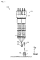
- FIG. 1 is a diagram illustrating a configuration of the take-up winding facility 100.
- the vertical direction specified in the diagram represents the direction of gravity.
- the take-up winding facility 100 combines a plurality of filaments F spun from a spinning machine 10 into a yarn Y, subject the yarn Y to drawing and other treatment, and wind up the yarn Y into a package P.
- the take-up winding facility 100 according to this embodiment mainly includes the spinning machine 10, a first godet roller pair 20, a second godet roller pair 30, and a winder 40.
- the spinning machine 10 spins a plurality of filaments F. Synthetic raw materials (raw materials of the filaments) are put into the spinning machine 10, and the spinning machine 10 melts the raw materials and sends them with pressure to be spun through spinnerets disposed on a spinning head 11. The spinning machine 10 is disposed on top of the take-up winding facility 100.
- the plurality of filaments F spun through the spinnerets of the spinning head 11 are combined into groups of a predetermined number of filaments F to form a plurality of yarns Y.
- the plurality of yarns Y thus obtained are forwarded downward and guided to the first godet roller pair 20 and the second godet roller pair 30.
- the winder 40 winds the yarns Y to form packages P. As shown in FIG. 2 , the winder 40 forms a plurality of packages P by winding the plurality of yarns Y, which are forwarded from the second godet roller pair 30, around corresponding bobbins 41. The winder 40 traverses the yarns Y by a traverse device 42.
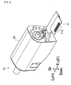
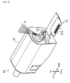
- FIGs. 3 and 4 are views of the yarn cutting apparatus 50 illustrating its configuration.
- the vertical direction specified in the diagram represents the direction of gravity.
- the lateral direction specified in the diagram represents a predetermined direction orthogonal to the vertical direction.
- the yarn cutting apparatus 50 cuts the plurality of yarns Y.
- the yarn cutting apparatus 50 mainly includes a yarn path regulating guide 51, a yarn shift guide 52, an aspirator 53, a cutter 54, and a main body unit 55.
- the yarn cutting apparatus 50 is disposed between the spinning machine 10 and the first godet roller pair 20 (see FIG. 1 ).
- the yarn path regulating guide 51 guides the plurality of yarns Y.
- the yarn path regulating guide 51 includes guide grooves 5 1g disposed in parallel to each other in the direction in which the plurality of yarns Y are aligned with each other, so as to guide the plurality of corresponding yarns Y.
- the plurality of yarns Y are threaded onto the respective guide groove 51g and thereby kept under a parallel state when forwarded to the first godet roller pair 20 (see FIG. 6 ).
- the yarn path regulating guide 51 is disposed at a lowest portion of the main body unit 55 (see FIG. 4 ).
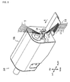
- the yarn shift guide 52 pulls the yarns Y fed on the guide grooves 5 1g of the yarn path regulating guide 51.
- the yarn shift guide 52 includes, at a distal end portion thereof, a hook portion 52h to hook the yarns Y fed on the guide grooves 51g (see FIGs. 4 and 7 ).
- the yarn shift guide 52 reciprocates along the direction in which the guide grooves 51g are disposed (the direction in which the plurality of yarns Y are aligned with each other) so as to cause the hook portion 52h to hook the yarns Y fed on the guide grooves 51g (see FIGs. 7 and 8 ).
- the yarn shift guide 52 is disposed further upstream than the yarn path regulating guide 51 (see FIG. 4 ).
- the aspirator 53 holds the yarns Y pulled by the yarn shift guide 52.
- the aspirator 53 includes an air suction inlet 53a to suck the pulled yarns Y
- the air suction inlet 53a sucks air in to ensure that the yarns Y pulled by the yarn shift guide 52 are sucked by and held at the air suction inlet 53a (see FIGs. 8 , 9 , and 10 ).
- the aspirator 53 is disposed further upstream than the yarn shift guide 52 (see FIG. 4 ).
- the cutter 54 cuts the yarns Y held by the aspirator 53.
- the cutter 54 is disposed on a movable seat 57, which is driven to reciprocate along the direction in which the guide grooves 51g are disposed (the direction in which the plurality of yarns Y are aligned with each other) (see Fig. 4 and 5 ).
- the movable seat 57 reciprocates along the direction in which the guide grooves 51g are disposed (the direction in which the plurality of yarns Y are aligned with each other) to cause the cutter 54 attached on the movable seat 57 to cut the yarns Y held by the aspirator 53 (see FIGs. 9 and 10 ).
- the movable seat 57 and the cutter 54 are disposed between the yarn shift guide 52 and the aspirator 53 (see FIG. 4 ).
- the aspirator 53 and the yarn shift guide 52 hold the yarns Y. This eliminates loosening of the yarns Y at the time of cutting the yarns Y. This, as a result, facilitates cutting of the yarns Y
- Another feature of the yarn cutting apparatus 50 is that the yarn shift guide 52, the aspirator 53, and the cutter 54 are disposed on one end side in the direction in which the yarns Y are aligned with each other, which is the direction in which the guide grooves 51 g are disposed.
- the yarn shift guide 52 and other elements are collectively disposed on one end side. This ensures a large space above the yarn path regulating guide 51. This, as a result, improves the workability of the yarn threading operation by the operator.
- Collectively disposing the yarn shift guide 52 and other elements on one end side also simplifies the yarn cutting apparatus 50 in structure and ensures reductions in size and cost.
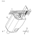
- FIGs. 6 to 10 are views of the yarn cutting apparatus 50 illustrating its operation.
- the vertical direction specified in the diagram represents the direction of gravity.
- the lateral direction specified in the diagram represents a predetermined direction orthogonal to the vertical direction.
- the plurality of yarns Y are fed onto the respective guide grooves 51 g and thereby kept under a parallel state when forwarded to the first godet roller pair 20.
- the yarn shift guide 52 is in stand-by state while being accommodated in the main body unit 55.
- the aspirator 53 is stopping sucking air in.
- the yarn cutting apparatus 50 drives the yarn shift guide 52. Specifically, the yarn cutting apparatus 50 drives the yarn shift guide 52 away from the main body unit 55 along the direction in which the yarns Y are aligned with each other, which is the direction in which the guide grooves 51g are disposed (see arrow A in FIGs. 4 and 7 ). In this respect, the yarn shift guide 52 moves forward with a back portion of the hook portion 52h thrusting past the yarns Y fed on the guide grooves 51g.
- the yarn cutting apparatus 50 also drives the yarn shift guide 52 when yarn-cut detection sensors 43 (see FIG. 2 ) sense a cutting of the yarns Y.
- the yarn-cut detection sensors 43 are disposed along the yarn paths of the corresponding yarns Y.
- the yarn shift guide 52 is driven upon sensing of cutting of at least one yarn Y.
- the yarn shift guide 52 is also driven when the operator presses a button 44 disposed on the winder 40.
- the yarn cutting apparatus 50 drives the yarn shift guide 52 closer to the main body unit 55 along the direction in which the yarns Y are aligned with each other, which is the direction in which the guide grooves 51g are disposed (see arrow A in FIGs. 4 and 8 ).
- the yarn shift guide 52 moves backward with the hook portion 52h hooking the yarns Y fed on the guide grooves 51g.
- the yarn shift guide 52 moves forward while thrusting past the yarns Y fed on the guide grooves 51g and then moves backward while hooking the yarns Y fed on the guide grooves 51g. This ensures shift of all of the yarns Y. All that is necessary to ensure this effect is the mere mechanism in which the yarn shift guide 52 is driven to reciprocate. This simplifies the yarn cutting apparatus 50 in structure and ensures reductions in size and cost.
- the yarn cutting apparatus 50 starts the suction of air at the aspirator 52. This ensures that the yarns Y pulled by the yarn shift guide 52 are held and sucked by the air suction inlet 53a.
- the yarn cutting apparatus 50 drives the movable seat 57 to carry out cutting. Specifically, the yarn cutting apparatus 50 drives the movable seat 57 attached with the cutter 54 to reciprocate away from or closer to the main body unit 55 along the direction in which the yarns Y are aligned with each other, which is the direction in which the guide grooves 51g are disposed (see arrow B in FIGs. 4 and 5 ).
- the yarn cutting apparatus 50 is configured to carry out a plurality of times of cutting. This ensures that even when not all the yarns Y are cut at a time as shown in FIG. 9 , a plurality of times of cutting cut all of the yarns Y as shown in FIG. 10 .
- the yarn cutting apparatus 50 drives the movable seat 57 attached with the cutter 54 to reciprocate away from or closer to the main body unit 55 along the direction in which the yarns Y are aligned with each other.
- the yarn cutting apparatus 50 cuts the yarns Y held by the aspirator 53 once or a plurality of times. This ensures cutting of all of the yarns Y.
- the yarn cutting apparatus 50 includes a regulating guide 56 disposed between the aspirator 53 and the cutter 54.
- the regulating guide 56 has a tip end groove 56g tapering toward the main body unit 55 along the direction in which the yarns Y are aligned with each other, which is the direction in which the guide grooves 51 g are disposed.
- the yarn cutting apparatus 50 guides all of the yarns Y pulled by the yarn shift guide 52 into the tip end groove 56g. This ensures collecting of the yarns Y at a predetermined place. This ensures that the yarn cutting apparatus 50 cuts all of the yarns Y with a few times of cutting by the cutter 54.
Landscapes
- Engineering & Computer Science (AREA)
- Textile Engineering (AREA)
- Coiling Of Filamentary Materials In General (AREA)
- Spinning Methods And Devices For Manufacturing Artificial Fibers (AREA)
- Treatment Of Fiber Materials (AREA)
Applications Claiming Priority (1)
| Application Number | Priority Date | Filing Date | Title |
|---|---|---|---|
| JP2010277344A JP5685432B2 (ja) | 2010-12-13 | 2010-12-13 | 糸切断装置 |
Publications (3)
| Publication Number | Publication Date |
|---|---|
| EP2463221A2 true EP2463221A2 (de) | 2012-06-13 |
| EP2463221A3 EP2463221A3 (de) | 2013-01-23 |
| EP2463221B1 EP2463221B1 (de) | 2014-08-13 |
Family
ID=45350671
Family Applications (1)
| Application Number | Title | Priority Date | Filing Date |
|---|---|---|---|
| EP20110192558 Active EP2463221B1 (de) | 2010-12-13 | 2011-12-08 | Garnschneidvorrichtung |
Country Status (3)
| Country | Link |
|---|---|
| EP (1) | EP2463221B1 (de) |
| JP (1) | JP5685432B2 (de) |
| CN (1) | CN102560711B (de) |
Cited By (5)
| Publication number | Priority date | Publication date | Assignee | Title |
|---|---|---|---|---|
| CN103820897A (zh) * | 2014-03-08 | 2014-05-28 | 福建凯邦锦纶科技有限公司 | 纺丝自主收拢切断装置 |
| WO2019081215A1 (de) | 2017-10-26 | 2019-05-02 | Oerlikon Textile Gmbh & Co. Kg | Fadenraffvorrichtung |
| CN111876836A (zh) * | 2015-10-30 | 2020-11-03 | 日本Tmt机械株式会社 | 纺丝卷绕设备 |
| EP4001192A1 (de) * | 2020-11-17 | 2022-05-25 | TMT Machinery, Inc. | Fadenschneide- und ansaugvorrichtung |
| EP4269303A1 (de) * | 2022-04-28 | 2023-11-01 | TMT Machinery, Inc. | Vorrichtung zum aufwickeln von gesponnenem garn |
Families Citing this family (13)
| Publication number | Priority date | Publication date | Assignee | Title |
|---|---|---|---|---|
| CN102776590B (zh) * | 2012-08-03 | 2014-08-27 | 井孝安 | 纺粘无纺布专用生头器 |
| JP6145340B2 (ja) * | 2013-07-05 | 2017-06-07 | Tmtマシナリー株式会社 | 紡糸引取機の糸掛け治具、及び、紡糸引取機の糸掛け方法 |
| JP6490074B2 (ja) * | 2013-08-22 | 2019-03-27 | エーリコン テクスティル ゲゼルシャフト ミット ベシュレンクテル ハフツング ウント コンパニー コマンディートゲゼルシャフトOerlikon Textile GmbH & Co. KG | 複数の合成糸を製造する装置 |
| DE102014007454A1 (de) * | 2014-05-21 | 2015-11-26 | Oerlikon Textile Gmbh & Co. Kg | Vorrichtung zum Abziehen und Verstecken einer synthetischen Fadenschar |
| JP6461705B2 (ja) * | 2014-05-29 | 2019-01-30 | Tmtマシナリー株式会社 | 糸切断装置 |
| JP6756573B2 (ja) * | 2015-10-30 | 2020-09-16 | Tmtマシナリー株式会社 | 自動糸掛け装置 |
| JP6527818B2 (ja) * | 2015-12-21 | 2019-06-05 | Tmtマシナリー株式会社 | 糸巻取機、糸掛け部材、及び、糸巻取機の糸掛け方法 |
| DE102017001090A1 (de) * | 2017-02-07 | 2018-08-09 | Oerlikon Textile Gmbh & Co. Kg | Verfahren und Vorrichtung zur Bedienung mehrerer Spinnpositionen einer Schmelzspinnanlage |
| CN108861865B (zh) * | 2017-05-16 | 2021-07-09 | 欧瑞康纺织有限及两合公司 | 一种卷绕装置中用于辅助卷筒更换的辅助装置 |
| JP7253431B2 (ja) | 2019-04-16 | 2023-04-06 | Tmtマシナリー株式会社 | 紡糸引取設備 |
| DE102021003549B4 (de) * | 2021-07-10 | 2023-08-10 | Oerlikon Textile Gmbh & Co. Kg | Fadenraffvorrichtung |
| DE102023004469A1 (de) * | 2023-11-07 | 2025-05-08 | Oerlikon Textile Gmbh & Co. Kg | Spulkopf zum Aufwickeln von synthetischen Fäden |
| CN119976532B (zh) * | 2025-04-17 | 2025-08-29 | 江苏恒力化纤股份有限公司 | 一种卷绕机纸管尾丝的切丝装置及其切丝方法 |
Citations (1)
| Publication number | Priority date | Publication date | Assignee | Title |
|---|---|---|---|---|
| JPH0726247B2 (ja) | 1987-08-17 | 1995-03-22 | 東レ株式会社 | 高速製糸における糸条の切断吸引処理方法およびその装置 |
Family Cites Families (10)
| Publication number | Priority date | Publication date | Assignee | Title |
|---|---|---|---|---|
| JPS5733269B2 (de) * | 1974-04-22 | 1982-07-16 | ||
| JPS62156307A (ja) * | 1985-12-27 | 1987-07-11 | Toray Ind Inc | 糸切れ処理装置 |
| JPH0811663B2 (ja) * | 1993-06-04 | 1996-02-07 | 株式会社山陽精機 | 糸条収束装置 |
| JPH11107031A (ja) * | 1997-10-02 | 1999-04-20 | Toray Eng Co Ltd | 糸条製造装置 |
| TW436532B (en) * | 1998-01-24 | 2001-05-28 | Barmag Barmer Maschf | Spinning line |
| JP2001192925A (ja) * | 1999-12-28 | 2001-07-17 | Murata Mach Ltd | 糸寄せ装置 |
| CN1230578C (zh) * | 2000-11-20 | 2005-12-07 | 苏拉有限及两合公司 | 纺丝设备 |
| JP2005041673A (ja) * | 2003-07-25 | 2005-02-17 | Teijin Fibers Ltd | 断糸処理装置 |
| CN201339079Y (zh) * | 2009-01-04 | 2009-11-04 | 江苏恒力化纤有限公司 | 一种集丝装置 |
| CN101550623B (zh) * | 2009-04-07 | 2010-09-15 | 江苏宏源纺机股份有限公司 | 被动式切丝器 |
-
2010
- 2010-12-13 JP JP2010277344A patent/JP5685432B2/ja active Active
-
2011
- 2011-12-01 CN CN201110392487.9A patent/CN102560711B/zh active Active
- 2011-12-08 EP EP20110192558 patent/EP2463221B1/de active Active
Patent Citations (1)
| Publication number | Priority date | Publication date | Assignee | Title |
|---|---|---|---|---|
| JPH0726247B2 (ja) | 1987-08-17 | 1995-03-22 | 東レ株式会社 | 高速製糸における糸条の切断吸引処理方法およびその装置 |
Cited By (9)
| Publication number | Priority date | Publication date | Assignee | Title |
|---|---|---|---|---|
| CN103820897A (zh) * | 2014-03-08 | 2014-05-28 | 福建凯邦锦纶科技有限公司 | 纺丝自主收拢切断装置 |
| CN103820897B (zh) * | 2014-03-08 | 2016-05-25 | 福建凯邦锦纶科技有限公司 | 纺丝自主收拢切断装置 |
| CN111876836A (zh) * | 2015-10-30 | 2020-11-03 | 日本Tmt机械株式会社 | 纺丝卷绕设备 |
| WO2019081215A1 (de) | 2017-10-26 | 2019-05-02 | Oerlikon Textile Gmbh & Co. Kg | Fadenraffvorrichtung |
| DE102017009994A1 (de) | 2017-10-26 | 2019-05-02 | Oerlikon Textile Gmbh & Co. Kg | Fadenraffvorrichtung |
| CN111315673A (zh) * | 2017-10-26 | 2020-06-19 | 欧瑞康纺织有限及两合公司 | 集线装置 |
| CN111315673B (zh) * | 2017-10-26 | 2021-08-17 | 欧瑞康纺织有限及两合公司 | 集线装置 |
| EP4001192A1 (de) * | 2020-11-17 | 2022-05-25 | TMT Machinery, Inc. | Fadenschneide- und ansaugvorrichtung |
| EP4269303A1 (de) * | 2022-04-28 | 2023-11-01 | TMT Machinery, Inc. | Vorrichtung zum aufwickeln von gesponnenem garn |
Also Published As
| Publication number | Publication date |
|---|---|
| CN102560711B (zh) | 2016-04-20 |
| EP2463221B1 (de) | 2014-08-13 |
| CN102560711A (zh) | 2012-07-11 |
| JP5685432B2 (ja) | 2015-03-18 |
| JP2012127011A (ja) | 2012-07-05 |
| EP2463221A3 (de) | 2013-01-23 |
Similar Documents
| Publication | Publication Date | Title |
|---|---|---|
| EP2463221B1 (de) | Garnschneidvorrichtung | |
| JP6080152B2 (ja) | 紡績機及びつなぎ合わせ工程の前に紡績糸の端部を除去する方法 | |
| JP6080153B2 (ja) | 紡績機及び紡績機における糸の製造を中断する方法 | |
| JP7516473B2 (ja) | 複数の紡糸された糸を仕掛けるための方法および装置 | |
| EP2567919B1 (de) | Garnschneide-/Garnsaugvorrichtung und Spinnaufwickler | |
| JP2011038225A (ja) | 紡績機 | |
| CN205241925U (zh) | 用于中断粗纱的进给的设备及包含该设备的包芯纱纺纱机 | |
| EP3115488B1 (de) | Streckvorrichtung für spinnrahmen | |
| CN107055212B (zh) | 用于运行工位的方法和工位 | |
| CN109930260B (zh) | 纺纱机和纱线捕捉方法 | |
| EP3025995A1 (de) | Garnwicklungsmaschine | |
| EP2966200A2 (de) | Spinnmaschine und spinnverfahren | |
| JPH11107031A (ja) | 糸条製造装置 | |
| EP3184475A1 (de) | Garnaufwicklungsvorrichtung, fadeneinfädelungselement und verfahren zum einfädeln eines fadens in die garnaufwicklungsvorrichtung | |
| CN105764823B (zh) | 变形机和用于操作变形机的卷绕站的方法 | |
| CN103510217B (zh) | 纤维机械及纤维机械的周期性不匀检测方法 | |
| CN110642095B (zh) | 纱线卷绕机 | |
| EP2436633A2 (de) | Leiterplatte für Garnwickelvorrichtung sowie Garnwickelvorrichtung | |
| EP2636624A2 (de) | Aufnahmevorrichtung | |
| EP2985371B1 (de) | Spinnmaschine | |
| CN115676513A (zh) | 用于抽出并卷绕丝线的设备 | |
| JP2014009052A (ja) | 繊維機械 | |
| CN108298369B (zh) | 卷取装置、纱线卷取单元及纱线卷取机 | |
| CN220283137U (zh) | 丝线加工机 | |
| EP2966199B1 (de) | Spinnmaschine und spinnverfahren |
Legal Events
| Date | Code | Title | Description |
|---|---|---|---|
| PUAI | Public reference made under article 153(3) epc to a published international application that has entered the european phase |
Free format text: ORIGINAL CODE: 0009012 |
|
| AK | Designated contracting states |
Kind code of ref document: A2 Designated state(s): AL AT BE BG CH CY CZ DE DK EE ES FI FR GB GR HR HU IE IS IT LI LT LU LV MC MK MT NL NO PL PT RO RS SE SI SK SM TR |
|
| AX | Request for extension of the european patent |
Extension state: BA ME |
|
| PUAL | Search report despatched |
Free format text: ORIGINAL CODE: 0009013 |
|
| AK | Designated contracting states |
Kind code of ref document: A3 Designated state(s): AL AT BE BG CH CY CZ DE DK EE ES FI FR GB GR HR HU IE IS IT LI LT LU LV MC MK MT NL NO PL PT RO RS SE SI SK SM TR |
|
| AX | Request for extension of the european patent |
Extension state: BA ME |
|
| RIC1 | Information provided on ipc code assigned before grant |
Ipc: B65H 67/048 20060101ALI20121219BHEP Ipc: B65H 57/28 20060101ALI20121219BHEP Ipc: B65H 54/88 20060101ALI20121219BHEP Ipc: B65H 57/16 20060101ALI20121219BHEP Ipc: B65H 54/71 20060101AFI20121219BHEP |
|
| 17P | Request for examination filed |
Effective date: 20130328 |
|
| 17Q | First examination report despatched |
Effective date: 20130507 |
|
| GRAP | Despatch of communication of intention to grant a patent |
Free format text: ORIGINAL CODE: EPIDOSNIGR1 |
|
| INTG | Intention to grant announced |
Effective date: 20140314 |
|
| GRAS | Grant fee paid |
Free format text: ORIGINAL CODE: EPIDOSNIGR3 |
|
| GRAA | (expected) grant |
Free format text: ORIGINAL CODE: 0009210 |
|
| AK | Designated contracting states |
Kind code of ref document: B1 Designated state(s): AL AT BE BG CH CY CZ DE DK EE ES FI FR GB GR HR HU IE IS IT LI LT LU LV MC MK MT NL NO PL PT RO RS SE SI SK SM TR |
|
| REG | Reference to a national code |
Ref country code: GB Ref legal event code: FG4D |
|
| REG | Reference to a national code |
Ref country code: AT Ref legal event code: REF Ref document number: 682080 Country of ref document: AT Kind code of ref document: T Effective date: 20140815 Ref country code: CH Ref legal event code: EP |
|
| REG | Reference to a national code |
Ref country code: IE Ref legal event code: FG4D |
|
| REG | Reference to a national code |
Ref country code: DE Ref legal event code: R096 Ref document number: 602011009037 Country of ref document: DE Effective date: 20140925 |
|
| REG | Reference to a national code |
Ref country code: NL Ref legal event code: VDEP Effective date: 20140813 |
|
| REG | Reference to a national code |
Ref country code: AT Ref legal event code: MK05 Ref document number: 682080 Country of ref document: AT Kind code of ref document: T Effective date: 20140813 |
|
| REG | Reference to a national code |
Ref country code: LT Ref legal event code: MG4D |
|
| PG25 | Lapsed in a contracting state [announced via postgrant information from national office to epo] |
Ref country code: LT Free format text: LAPSE BECAUSE OF FAILURE TO SUBMIT A TRANSLATION OF THE DESCRIPTION OR TO PAY THE FEE WITHIN THE PRESCRIBED TIME-LIMIT Effective date: 20140813 Ref country code: ES Free format text: LAPSE BECAUSE OF FAILURE TO SUBMIT A TRANSLATION OF THE DESCRIPTION OR TO PAY THE FEE WITHIN THE PRESCRIBED TIME-LIMIT Effective date: 20140813 Ref country code: SE Free format text: LAPSE BECAUSE OF FAILURE TO SUBMIT A TRANSLATION OF THE DESCRIPTION OR TO PAY THE FEE WITHIN THE PRESCRIBED TIME-LIMIT Effective date: 20140813 Ref country code: BG Free format text: LAPSE BECAUSE OF FAILURE TO SUBMIT A TRANSLATION OF THE DESCRIPTION OR TO PAY THE FEE WITHIN THE PRESCRIBED TIME-LIMIT Effective date: 20141113 Ref country code: PT Free format text: LAPSE BECAUSE OF FAILURE TO SUBMIT A TRANSLATION OF THE DESCRIPTION OR TO PAY THE FEE WITHIN THE PRESCRIBED TIME-LIMIT Effective date: 20141215 Ref country code: NO Free format text: LAPSE BECAUSE OF FAILURE TO SUBMIT A TRANSLATION OF THE DESCRIPTION OR TO PAY THE FEE WITHIN THE PRESCRIBED TIME-LIMIT Effective date: 20141113 Ref country code: FI Free format text: LAPSE BECAUSE OF FAILURE TO SUBMIT A TRANSLATION OF THE DESCRIPTION OR TO PAY THE FEE WITHIN THE PRESCRIBED TIME-LIMIT Effective date: 20140813 Ref country code: GR Free format text: LAPSE BECAUSE OF FAILURE TO SUBMIT A TRANSLATION OF THE DESCRIPTION OR TO PAY THE FEE WITHIN THE PRESCRIBED TIME-LIMIT Effective date: 20141114 |
|
| PG25 | Lapsed in a contracting state [announced via postgrant information from national office to epo] |
Ref country code: LV Free format text: LAPSE BECAUSE OF FAILURE TO SUBMIT A TRANSLATION OF THE DESCRIPTION OR TO PAY THE FEE WITHIN THE PRESCRIBED TIME-LIMIT Effective date: 20140813 Ref country code: HR Free format text: LAPSE BECAUSE OF FAILURE TO SUBMIT A TRANSLATION OF THE DESCRIPTION OR TO PAY THE FEE WITHIN THE PRESCRIBED TIME-LIMIT Effective date: 20140813 Ref country code: AT Free format text: LAPSE BECAUSE OF FAILURE TO SUBMIT A TRANSLATION OF THE DESCRIPTION OR TO PAY THE FEE WITHIN THE PRESCRIBED TIME-LIMIT Effective date: 20140813 Ref country code: CY Free format text: LAPSE BECAUSE OF FAILURE TO SUBMIT A TRANSLATION OF THE DESCRIPTION OR TO PAY THE FEE WITHIN THE PRESCRIBED TIME-LIMIT Effective date: 20140813 Ref country code: IS Free format text: LAPSE BECAUSE OF FAILURE TO SUBMIT A TRANSLATION OF THE DESCRIPTION OR TO PAY THE FEE WITHIN THE PRESCRIBED TIME-LIMIT Effective date: 20141213 Ref country code: RS Free format text: LAPSE BECAUSE OF FAILURE TO SUBMIT A TRANSLATION OF THE DESCRIPTION OR TO PAY THE FEE WITHIN THE PRESCRIBED TIME-LIMIT Effective date: 20140813 |
|
| PG25 | Lapsed in a contracting state [announced via postgrant information from national office to epo] |
Ref country code: NL Free format text: LAPSE BECAUSE OF FAILURE TO SUBMIT A TRANSLATION OF THE DESCRIPTION OR TO PAY THE FEE WITHIN THE PRESCRIBED TIME-LIMIT Effective date: 20140813 |
|
| PG25 | Lapsed in a contracting state [announced via postgrant information from national office to epo] |
Ref country code: RO Free format text: LAPSE BECAUSE OF FAILURE TO SUBMIT A TRANSLATION OF THE DESCRIPTION OR TO PAY THE FEE WITHIN THE PRESCRIBED TIME-LIMIT Effective date: 20140813 Ref country code: SK Free format text: LAPSE BECAUSE OF FAILURE TO SUBMIT A TRANSLATION OF THE DESCRIPTION OR TO PAY THE FEE WITHIN THE PRESCRIBED TIME-LIMIT Effective date: 20140813 Ref country code: EE Free format text: LAPSE BECAUSE OF FAILURE TO SUBMIT A TRANSLATION OF THE DESCRIPTION OR TO PAY THE FEE WITHIN THE PRESCRIBED TIME-LIMIT Effective date: 20140813 Ref country code: DK Free format text: LAPSE BECAUSE OF FAILURE TO SUBMIT A TRANSLATION OF THE DESCRIPTION OR TO PAY THE FEE WITHIN THE PRESCRIBED TIME-LIMIT Effective date: 20140813 Ref country code: CZ Free format text: LAPSE BECAUSE OF FAILURE TO SUBMIT A TRANSLATION OF THE DESCRIPTION OR TO PAY THE FEE WITHIN THE PRESCRIBED TIME-LIMIT Effective date: 20140813 Ref country code: IT Free format text: LAPSE BECAUSE OF FAILURE TO SUBMIT A TRANSLATION OF THE DESCRIPTION OR TO PAY THE FEE WITHIN THE PRESCRIBED TIME-LIMIT Effective date: 20140813 |
|
| REG | Reference to a national code |
Ref country code: DE Ref legal event code: R097 Ref document number: 602011009037 Country of ref document: DE |
|
| PG25 | Lapsed in a contracting state [announced via postgrant information from national office to epo] |
Ref country code: PL Free format text: LAPSE BECAUSE OF FAILURE TO SUBMIT A TRANSLATION OF THE DESCRIPTION OR TO PAY THE FEE WITHIN THE PRESCRIBED TIME-LIMIT Effective date: 20140813 |
|
| PLBE | No opposition filed within time limit |
Free format text: ORIGINAL CODE: 0009261 |
|
| STAA | Information on the status of an ep patent application or granted ep patent |
Free format text: STATUS: NO OPPOSITION FILED WITHIN TIME LIMIT |
|
| PG25 | Lapsed in a contracting state [announced via postgrant information from national office to epo] |
Ref country code: BE Free format text: LAPSE BECAUSE OF NON-PAYMENT OF DUE FEES Effective date: 20141231 |
|
| 26N | No opposition filed |
Effective date: 20150515 |
|
| PG25 | Lapsed in a contracting state [announced via postgrant information from national office to epo] |
Ref country code: LU Free format text: LAPSE BECAUSE OF FAILURE TO SUBMIT A TRANSLATION OF THE DESCRIPTION OR TO PAY THE FEE WITHIN THE PRESCRIBED TIME-LIMIT Effective date: 20141208 |
|
| REG | Reference to a national code |
Ref country code: CH Ref legal event code: PL |
|
| REG | Reference to a national code |
Ref country code: IE Ref legal event code: MM4A |
|
| REG | Reference to a national code |
Ref country code: FR Ref legal event code: ST Effective date: 20150831 |
|
| PG25 | Lapsed in a contracting state [announced via postgrant information from national office to epo] |
Ref country code: CH Free format text: LAPSE BECAUSE OF NON-PAYMENT OF DUE FEES Effective date: 20141231 Ref country code: LI Free format text: LAPSE BECAUSE OF NON-PAYMENT OF DUE FEES Effective date: 20141231 Ref country code: IE Free format text: LAPSE BECAUSE OF NON-PAYMENT OF DUE FEES Effective date: 20141208 |
|
| PG25 | Lapsed in a contracting state [announced via postgrant information from national office to epo] |
Ref country code: SI Free format text: LAPSE BECAUSE OF FAILURE TO SUBMIT A TRANSLATION OF THE DESCRIPTION OR TO PAY THE FEE WITHIN THE PRESCRIBED TIME-LIMIT Effective date: 20140813 Ref country code: FR Free format text: LAPSE BECAUSE OF NON-PAYMENT OF DUE FEES Effective date: 20141231 |
|
| PG25 | Lapsed in a contracting state [announced via postgrant information from national office to epo] |
Ref country code: SM Free format text: LAPSE BECAUSE OF FAILURE TO SUBMIT A TRANSLATION OF THE DESCRIPTION OR TO PAY THE FEE WITHIN THE PRESCRIBED TIME-LIMIT Effective date: 20140813 |
|
| PG25 | Lapsed in a contracting state [announced via postgrant information from national office to epo] |
Ref country code: MC Free format text: LAPSE BECAUSE OF FAILURE TO SUBMIT A TRANSLATION OF THE DESCRIPTION OR TO PAY THE FEE WITHIN THE PRESCRIBED TIME-LIMIT Effective date: 20140813 |
|
| PG25 | Lapsed in a contracting state [announced via postgrant information from national office to epo] |
Ref country code: HU Free format text: LAPSE BECAUSE OF FAILURE TO SUBMIT A TRANSLATION OF THE DESCRIPTION OR TO PAY THE FEE WITHIN THE PRESCRIBED TIME-LIMIT; INVALID AB INITIO Effective date: 20111208 Ref country code: MT Free format text: LAPSE BECAUSE OF FAILURE TO SUBMIT A TRANSLATION OF THE DESCRIPTION OR TO PAY THE FEE WITHIN THE PRESCRIBED TIME-LIMIT Effective date: 20140813 Ref country code: TR Free format text: LAPSE BECAUSE OF FAILURE TO SUBMIT A TRANSLATION OF THE DESCRIPTION OR TO PAY THE FEE WITHIN THE PRESCRIBED TIME-LIMIT Effective date: 20140813 Ref country code: BE Free format text: LAPSE BECAUSE OF FAILURE TO SUBMIT A TRANSLATION OF THE DESCRIPTION OR TO PAY THE FEE WITHIN THE PRESCRIBED TIME-LIMIT Effective date: 20140813 |
|
| GBPC | Gb: european patent ceased through non-payment of renewal fee |
Effective date: 20151208 |
|
| PG25 | Lapsed in a contracting state [announced via postgrant information from national office to epo] |
Ref country code: GB Free format text: LAPSE BECAUSE OF NON-PAYMENT OF DUE FEES Effective date: 20151208 |
|
| PG25 | Lapsed in a contracting state [announced via postgrant information from national office to epo] |
Ref country code: MK Free format text: LAPSE BECAUSE OF FAILURE TO SUBMIT A TRANSLATION OF THE DESCRIPTION OR TO PAY THE FEE WITHIN THE PRESCRIBED TIME-LIMIT Effective date: 20140813 |
|
| PG25 | Lapsed in a contracting state [announced via postgrant information from national office to epo] |
Ref country code: AL Free format text: LAPSE BECAUSE OF FAILURE TO SUBMIT A TRANSLATION OF THE DESCRIPTION OR TO PAY THE FEE WITHIN THE PRESCRIBED TIME-LIMIT Effective date: 20140813 |
|
| PGFP | Annual fee paid to national office [announced via postgrant information from national office to epo] |
Ref country code: DE Payment date: 20241217 Year of fee payment: 14 |