EP2462279B1 - Kombination eines pressfilzes mit einem presswalzenbezug und/oder einem saugwalzenbezug für eine papiermaschine - Google Patents
Kombination eines pressfilzes mit einem presswalzenbezug und/oder einem saugwalzenbezug für eine papiermaschine Download PDFInfo
- Publication number
- EP2462279B1 EP2462279B1 EP10724334.7A EP10724334A EP2462279B1 EP 2462279 B1 EP2462279 B1 EP 2462279B1 EP 10724334 A EP10724334 A EP 10724334A EP 2462279 B1 EP2462279 B1 EP 2462279B1
- Authority
- EP
- European Patent Office
- Prior art keywords
- range
- press
- suction
- roller covering
- groove
- Prior art date
- Legal status (The legal status is an assumption and is not a legal conclusion. Google has not performed a legal analysis and makes no representation as to the accuracy of the status listed.)
- Not-in-force
Links
Images

Classifications
-
- D—TEXTILES; PAPER
- D21—PAPER-MAKING; PRODUCTION OF CELLULOSE
- D21F—PAPER-MAKING MACHINES; METHODS OF PRODUCING PAPER THEREON
- D21F3/00—Press section of machines for making continuous webs of paper
- D21F3/02—Wet presses
- D21F3/08—Pressure rolls
- D21F3/086—Pressure rolls having a grooved surface
-
- D—TEXTILES; PAPER
- D21—PAPER-MAKING; PRODUCTION OF CELLULOSE
- D21F—PAPER-MAKING MACHINES; METHODS OF PRODUCING PAPER THEREON
- D21F3/00—Press section of machines for making continuous webs of paper
- D21F3/02—Wet presses
- D21F3/10—Suction rolls, e.g. couch rolls
- D21F3/105—Covers thereof
-
- D—TEXTILES; PAPER
- D21—PAPER-MAKING; PRODUCTION OF CELLULOSE
- D21F—PAPER-MAKING MACHINES; METHODS OF PRODUCING PAPER THEREON
- D21F7/00—Other details of machines for making continuous webs of paper
- D21F7/08—Felts
- D21F7/083—Multi-layer felts
Definitions
- the present invention relates to the combination of a press felt with a press roll cover and / or a Saugwalzenbezug which in the press section of a paper machine or generally in a machine for producing web material, such.
- a press felt with a press roll cover and / or a Saugwalzenbezug which in the press section of a paper machine or generally in a machine for producing web material, such.
- a substantial portion of the liquid contained therein, generally water, is withdrawn in a press section from the starting material used to produce paper. This is done by passing the material on or between two press felts through generally several press nips used in conjunction with a press roll and / or a suction roll.
- the aim of this process is to extract the largest possible portion of the liquid from the material, at the same time reducing the energy input, in particular to create a negative pressure in the area of one or more suction rolls.
- the GB 1157407 A relates to improvements for suction rolls relating to the shape and number of surface forms in the elastic roll cover.
- the EP 2072675 A2 describes a papermaking fabric containing a proportion of polymer to improve the recovery capacity of the papermachine fabric and reduce the rewet of the fibrous web. It is therefore an object of the present invention to provide a combination of a press felt with a press roll cover and / or a To specify suction roll cover for a paper machine, which brings with reduced drainage property with a lower energy consumption.
- the object is achieved by a combination of a press felt with a press roll cover and / or a suction roll cover for a paper machine, comprising: a) a porous press felt having a support structure and polyurethane material incorporated in the support structure, the polyurethane material in the press felt having an area content in the range from 50g / m2 to 700g / m2, and wherein the press felt has a void volume fraction in the range of less than 600 cm3 / m2, preferably less than 500 cm3 / m2, most preferably less than 400 cm3 / m2; b) a press roll cover having a circumferential groove surface structure with a groove width in the range of 0.5mm to 1.5mm, a groove pitch in the range of 1.5mm to 2.5mm and a groove depth in the range of 1.5mm to 4mm, the proportion of an open groove Surface on the entire surface of the press roll cover in the range of 20% to 50%, and / or a Saugwalzenbezug with
- the object is achieved by a combination of a press felt with a press roll cover and / or a suction roll cover for a paper machine, comprising: a) a porous press felt with a support structure and with at least one layer formed as a scrim or Kettengewirk layer of non-woven Material, wherein the press felt has a void volume fraction in the range of less than 600 cm 3 / m 2, preferably less than 500 cm 3 / m 2, most preferably less than 400 cm 3 / m 2 b) a press roll cover having a circumferential groove surface structure with a groove width in the range of 0.5mm to 1.5mm, a groove spacing in the range of 1.5mm to 2.5mm and a groove depth in the range of 1.5mm to 4mm, the proportion of an open surface at the Overall surface of the press roll cover is in the range of 20% to 50%, and / or a Saugwalzenbezug with a commandssrillenoberfestFig.
- the press roll cover comprises a hole assembly having a plurality of blind holes not completely passing through the press roll cover and formed with its top groove surface structure, the open surface being provided by the circumferential groove surface structure and the hole assembly ,
- its hole arrangement comprises a plurality of blind holes which are not completely penetrating and which are formed with their upper groove surface structure having a circumferential groove upper surface structure.
- the holes of the hole arrangement of the suction roll cover and / or the hole arrangement of the press roll cover have a diameter in the range of 2 mm to 5 mm.
- the thickness of the press roll cover or the Saugwalzenbezugs can be in the range of 10 mm to 13 mm.
- the comparatively small void volume fraction can also be achieved, for example be used when used as a support structure woven material and the porosity is provided by appropriate design of a supported on this support structure and thus incorporated into this coating of polyurethane material.
- the invention further relates to a paper machine with a press section, in which a combination according to the invention is provided.
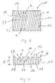
- the Fig. 1 and 2 show representations of a suction roller used for example in a suction roller 10. It can be seen in the supervision of Fig. 1 It comprises a plurality of groove portions 14 juxtaposed transversely to the roll longitudinal direction. These groove portions 14, which are slightly inclined with respect to the circumferential direction due to the helical winding structure, have a width b in the range of 0.5 mm to 1.5 mm and a mutual distance a in the range of 1.5 mm to 2.5 mm.
- the groove depth t is in a range of 1.5 mm to 4 mm.
- a hole assembly 16 is further formed, which in the supervision of Fig. 1 is shown only in a partial area.
- the hole assembly 16 includes a plurality of the suction roll cover 10 completely penetrating Suction holes 18 through which the withdrawn from the paper to be produced liquid can be sucked through.
- the hole assembly 16 further includes a plurality of blind holes 20 which, like the suction holes 18, are open to an upper surface 22 but are not completely open through the suction roll pad formed with a thickness d in the range of 10 to 13 mm 10 extend therethrough.
- the suction holes 18 and the blind holes 20 can, as in Fig. 2 are illustrated, have different diameters, wherein the diameter of these holes is preferably in the range of 2 mm to 5 mm. Also, for example, like the Fig. 1 This illustrates that all suction holes 18 are formed with the same diameter and all blind holes 20 are formed with the same diameter, wherein the diameter of the suction holes 18 is not necessarily equal to the diameter of the blind holes 20 must be.
- the suction holes 18 and the blind holes 20 are distributed in a uniform pattern over the suction roll cover 10 in such a way that, as the Fig. 1 and 2 illustrate, at least most, preferably all suction holes 18 and blind holes 20 a groove portion 14 at least cut. This means that the liquid received in a groove section 14 can then pass into holes 18 or 20 and thus can be removed from the area of the paper to be produced.
- an open surface is provided that is in the range of 30% to 50% relative to the entire surface, that is, substantially formed by a cylindrical peripheral surface of the suction roll cover , With this comparatively large surface portion over which liquid can be discharged directly, an excellent drainage capacity is achieved in connection with the liquid receiving volume formed by the groove structuring and the various holes 18, 20.
- the void volume fraction in the suction roll cover 10 is preferably in a range of 200 to 1500 cm 3 / m 2 .
- a press roller cover used for a press roller in a press section of a paper machine may be formed as in Figs Fig. 1 and 2 in principle and in particular with regard to theticiansrillenober lake Wegneck GmbH Ltd.
- a hole assembly 16 may be provided, but not including suction holes 18, but only the blind holes 20.
- the open surface provided by the blind holes 20 and the circumferential groove surface structure 12 is provided in a proportion of 20% to 50% on the entire surface, and the void volume ratio may be in the range of 200 to 1500 cm 3 / m 2 .
- such roll covers can be constructed, for example, with polyurethane material and have a modulus of elasticity in the range of 50 N / mm 2 to 500 N / mm 2 .
- suction or press roller covers In order to be able to optimally utilize the dewatering properties provided by the suction or press roller covers described above, these are used according to the invention in conjunction with a seam or seamless press felt.
- This press felt in particular compared to the roll covers a comparatively small void volume fraction of less than 600 cm 3 / m 2 , preferably less than 500 cm 3 / m 2 , most preferably less than 400 cm 3 / m 2 , on.
- the cavity volume of the press felt, just as in the above-described roll covers, for example, at a pressure of 5 MPa on an area of 10 cm x 10 cm are determined in a preconditioned in water overnight press felt.
- This void volume can be provided by providing the press felt at least one ply of non-woven fiber / yarn material, for example constructed with monofilaments or conventional yarns.
- nonwoven material may comprise, for example, a monolayer or multilayer scrim, a nonwoven material or warp knit.
- the use of a composite of a plurality of spirally or helically wound and connected by plug-wires connected elements composite represents the use of non-woven material in the context of the present invention.
- the press felt can also be formed in multiple layers and comprise at least one such layer of nonwoven material.
- Such nonwoven material has a comparatively low porosity, in particular when it is non-woven or also designed as warp knit fabric, in comparison to woven fiber or thread material. This can be further supported by the fact that polyurethane material is introduced into the nonwoven material or at least one layer thereof, which thus further reduces the void volume fraction. This is in the Fig. 3 illustrated.
- the fiber material 30 shown with a dashed surface constructed, for example, as a nonwoven material, into which partially also polyurethane material 32 is embedded.
- This can be produced, for example, by introducing small polyurethane particles 34 into the nonwoven fibrous material and then melting them by applying heat and / or pressure, so that, with appropriate deformation of the polyurethane particles 34, a substantially coherent composite of polyurethane material is formed, which nonetheless produces a Retains pore structure in the press felt thus constructed.
- the Fig. 4 shows a microscope representation of the surface of a so-built press felt, in which the substantially randomly distributed fibers of the fiber material can be seen, as well as this enclosing, so basically incorporated into the fiber material polyurethane material.
- polyurethane material By incorporating polyurethane material into the nonwoven fibrous material used here as a support structure, not only is the porosity influenced, but also the elasticity of the press felt is adjusted so that, in cooperation with the roll coverings mentioned above, it leads to improved drainage behavior. It has been found that, especially when the polyurethane material is provided with an area content of 50 g / m 2 to 700 g / m 2 , excellent drainage properties can be achieved with comparatively little remoistening.
- this may in principle be formed with a woven support structure, for example, in the same polyurethane material is integrated, either in the above-explained sense that the warp and / or weft threads of the fabric used as a support structure with the polyurethane material below Retention of a certain porosity are coated, or such that on at least one side of the support structure, a substantially closed composite of the polyurethane material is generated.
- the relatively large open surface portion of the relatively large and deep groove structure, the comparatively small modulus of elasticity of the polyurethane material used, is comparatively large Cavity volume fraction produces a constant nip pressure in a press section of a paper machine, in particular in the roll covers or the proposed hole arrangements.
- a press felt can contribute, which comprises one or more polyurethane systems, possibly on a support structure, which have a lower void volume, than a conventionally produced by needling press felt.
- the design of the press section of the paper machine has an influence on the dewatering or on the dry content of the paper web.
- nip-dewatering ie the drainage in the press nip, and the suction through a so-called.
- Uhle box outside the press nip Both options are well known, so that a detailed description can be omitted here.
- the vacuums which abut in a suction or suction press roll in a known manner, for example, by at least one suction box usually in two zones can be reduced or even switched off, the drainage remains the same or even improved. It is thus possible to achieve the same dry content or even an increase in dry content despite a lower vacuum in a first suction zone of a suction press roll, so that a lowering of the vacuum can take place in a second suction zone of the suction press roll. This was confirmed in tests with all suction press roll surface designs and all press felts. It is thus possible to provide the vacuum in only one suction zone, suction in other zones can be omitted, which has a positive effect on the energy balance.
- the suction power can be significantly reduced.
- the Uhle box can even be switched off.
- Total drainage may be maintained substantially neutral in presses having multiple press nips using suction press roll covers with suction holes 18 and circumferential groove surface structure 12.
Landscapes
- Paper (AREA)
Description
- Die vorliegende Erfindung betrifft die Kombination eines Pressfilzes mit einem Presswalzenbezug und/oder einem Saugwalzenbezug, welche in der Presspartie einer Papiermaschine bzw. allgemein in einer Maschine zur Herstellung von Bahnmaterial, wie z. B. Papier oder Karton, eingesetzt werden kann.
- Bei der Herstellung von Papier wird in einer Presspartie dem zur Herstellung von Papier eingesetzten Ausgangsmaterial ein wesentlicher Teil der darin enthaltenen Flüssigkeit, im allgemeinen Wasser, entzogen. Dies erfolgt dadurch, dass das Material auf einem bzw. zwischen zwei Pressfilzen durch im allgemeinen mehrere Pressnips hindurch geführt wird, die in Verbindung mit einer Presswalze und/oder einer Saugwalze verwendet werden. Ziel bei diesem Prozess ist es, dem Material den größtmöglichen Anteil der Flüssigkeit zu entziehen, wobei gleichzeitig der Energieeinsatz, vor allem zur Erzeugung eines Unterdrucks im Bereich einer oder mehrerer Saugwalzen, verringert werden soll.
- Beispielsweise geht aus der
EP1247895 A2 eine Schuhpresse mit einem umlaufenden Belt zur Verwendung in einer Pressenpartie einer Papier- oder ähnlichen Maschine hervor. Es sind diverse Oberflächenstrukturen des Belts beschrieben, die die Entwässerungskapazität steigern sollen. - Die
GB 1157407 A - Aus der
GB 2095368 A - Die
EP 2072675 A2 beschreibt eine Papiermaschinenbespannung, welche einen Anteil von Polymer enthält, um das Rückstellungsvermögen der Papiermaschinenbespannung zu verbessern und die Rückbefeuchtung der Faserstoffbahn zu verringern. Es ist daher Aufgabe der vorliegenden Erfindung, eine Kombination eines Pressfilzes mit einem Presswalzenbezug und/oder einem Saugwalzenbezug für eine Papiermaschine anzugeben, welche bei verbesserter Entwässerungseigenschaft einen geringeren Energieeinsatz mit sich bringt. - Erfindungsgemäß wird die Aufgabe gelöst durch eine Kombination eines Pressfilzes mit einem Presswalzenbezug und/oder einem Saugwalzenbezug für eine Papiermaschine, umfassend: a) einen porösen Pressfilz mit einer Tragestruktur und in die Tragestruktur eingebundenem Polyurethanmaterial, wobei das Polyurethanmaterial in dem Pressfilz mit einem Flächengehalt im Bereich von 50g/m2 bis 700g/m2 vorgesehen ist und wobei der Pressfilz einen Hohlraumvolumenanteil im Bereich von weniger als 600 cm3/m2, vorzugsweise weniger als 500 cm3/m2, am meisten bevorzugt weniger als 400 cm3/m2, aufweist; b) einen Presswalzenbezug mit einer Umfangsrillenoberflächenstruktur mit einer Rillenbreite im Bereich von 0,5mm bis 1,5mm, einem Rillenabstand im Bereich von 1,5mm bis 2,5mm und einer Rillentiefe im Bereich von 1,5mm bis 4mm, wobei der Anteil einer offenen Oberfläche an der Gesamtoberfläche des Presswalzenbezugs im Bereich von 20% bis 50% liegt, und/oder einen Saugwalzenbezug mit einer Umfangsrillenoberflächenstruktur mit einer Rillenbreite im Bereich von 0,5 mm bis 1,5 mm, einem Rillenabstand im Bereich von 1,5 mm bis 2,5 mm und einer Rillentiefe im Bereich von 1,5 mm bis 4 mm sowie mit einer Lochanordnung mit einer Mehrzahl von den Saugwalzenbezug vollständig durchsetzenden Sauglöchern, wobei der Anteil einer offenen Oberfläche an der Gesamtoberfläche des Saugwalzenbezugs im Bereich von 30% bis 50% liegt, wobei der Presswalzenbezug und/oder der Saugwalzenbezug mit Polyurethanmaterial aufgebaut ist und einen Elastizitätsmodul im Bereich von 50N/mm2 bis 500N/mm2, ein Hohlraumvolumenanteil im Bereich von 200 bis 1500 cm3/m2 aufweist.
- Gemäß einer alternativen Ausgestaltungsvariante der Erfindung wird die Aufgabe gelöst durch eine Kombination eines Pressfilzes mit einem Presswalzenbezug und/oder einem Saugwalzenbezug für eine Papiermaschine, umfassend: a) einen porösen Pressfilz mit einer Tragestruktur und mit wenigstens einer als Fadengelege oder Kettengewirk ausgebildeten Lage aus nicht gewebtem Material, wobei der Pressfilz einen Hohlraumvolumenanteil im Bereich von weniger als 600 cm3/m2, vorzugsweise weniger als 500 cm3/m2, am meisten bevorzugt weniger als 400 cm3/m2, aufweist, b) einen Presswalzenbezug mit einer Umfangsrillenoberflächenstruktur mit einer Rillenbreite im Bereich von 0,5mm bis 1,5mm, einem Rillenabstand im Bereich von 1,5mm bis 2,5mm und einer Rillentiefe im Bereich von 1,5mm bis 4mm, wobei der Anteil einer offenen Oberfläche an der Gesamtoberfläche des Presswalzenbezugs im Bereich von 20% bis 50% liegt, und/oder einen Saugwalzenbezug mit einer Umfangsrillenoberflächenstruktur mit einer Rillenbreite im Bereich von 0,5 mm bis 1,5 mm, einem Rillenabstand im Bereich von 1,5 mm bis 2,5 mm und einer Rillentiefe im Bereich von 1,5 mm bis 4 mm sowie mit einer Lochanordnung mit einer Mehrzahl von den Saugwalzenbezug vollständig durchsetzenden Sauglöchern, wobei der Anteil einer offenen Oberfläche an der Gesamtoberfläche des Saugwalzenbezugs im Bereich von 30% bis 50% liegt, wobei der Presswalzenbezug und/oder der Saugwalzenbezug mit Polyurethanmaterial aufgebaut ist und einen Elastizitätsmodul im Bereich von 50N/mm2 bis 500N/mm2, ein Hohlraumvolumenanteil im Bereich von 200 bis 1500 cm3/m2 aufweist.
- Es wurde festgestellt, dass durch die Kombination eines speziell aufgebauten Pressfiilzes, der eine vergleichsweise geringe Porosität, also einen vergleichsweise geringen Hohlraumvolumenanteil aufweist, mit einem wie vorangehend angegeben aufgebauten Bezug für eine Presswalze bzw. eine Saugwalze ein sehr gutes Entwässerungsverhalten erzielt wird, während gleichzeitig aufgrund der vergleichsweise offenen Gestaltung des Walzenbezugs insbesondere im Bereich einer Saugwalze die eingesetzte Energie zum Erzeugen des Unterdrucks bzw. zum Abziehen von Flüssigkeit durch Unterdruck verringert werden kann.
- Um das Flüssigkeitsaufnahmevermögen auch im Presswalzenbezug weiter zu verbessern, wird vorgeschlagen, dass der Presswalzenbezug eine Lochanordnung mit einer Mehrzahl von den Presswalzenbezug nicht vollständig durchsetzenden und zu dessen mit Umfangsrillenoberflächenstruktur ausgebildeter Oberseite offenen Blindlöchern umfasst, wobei die offene Oberfläche durch die Umfangsrillenoberflächenstruktur und die Lochanordnung bereitgestellt ist.
- Auch bei dem Saugwalzenbezug kann vorgesehen sein, dass dessen Lochanordnung eine Mehrzahl von diesen nicht vollständig durchsetzenden und zu dessen mit Umfangsrillenoberfilächenstruktur ausgebildeter Oberseite offenen Blindlöchern umfasst.
- Um die Aufnahme von Flüssigkeit in der Lochanordnung weiter zu verbessern, wird vorgeschlagen, dass die Löcher der Lochanordnung des Saugwalzenbezugs und/oder der Lochanordnung des Presswalzenbezugs einen Durchmesser im Bereich von 2 mm bis 5 mm aufweisen.
- Weiterhin kann die Dicke des Presswalzenbezugs bzw. auch des Saugwalzenbezugs im Bereich von 10 mm bis 13 mm liegen.
- Um im Bereich des bei der erfindungsgemäßen Kombination vorgesehenen Pressfilzes dafür zu sorgen, dass dieser mit vergleichsweise geringem Hohlraumvolumenanteil ausgebildet ist, wodurch erreicht werden kann, dass der größere Anteil des aus dem zu fertigenden Papier herausgepressten Wassers in Richtung Walzenbezug gelangt, wird vorgeschlagen, dass in wenigstens eine Lage des Pressfilzes aus nicht gewebtem Material Polyurethanmaterial eingebunden ist. Das Vorsehen von Polyurethanmaterial in dem nicht gewebten Material verringert den Hohlraumvolumenanteil des nicht gewebten Materials, wobei dieses Material bereits einen deutlich geringeren Hohfraumvolumenanteil aufweist als beispielsweise Webmaterial.
- Bei Vorsehen einer Tragestruktur mit darin eingebundenem Polyurethanmaterial kann der vergleichsweise geringe Hohlraumvolumenanteil beispielsweise auch erreicht werden, wenn als Tragestruktur gewebtes Material eingesetzt wird und die Porosität durch entsprechende Ausgestaltung einer an dieser Tragestruktur getragenen und somit in diese eingebundenen Beschichtung aus Polyurethanmaterial bereitgestellt wird.
- Die Erfindung betrifft ferner eine Papiermaschine mit einer Pressenpartie, bei welcher eine erfindungsgemäße Kombination vorgesehen ist.
- Die vorliegende Erfindung wird nachfolgend mit Bezug auf die beiliegenden Figuren beschrieben. Es zeigt:
- Fig. 1
- eine Aufsicht auf einen Oberflächenbereich eines Saugwalzenbezugs;
- Fig. 2
- eine Schnittdarstellung eines Saugwalzenbezugs;
- Fig. 3
- eine Teil-Prinzipdarstellung eines mit eingebettetem Polyurethanmaterial aufgebauten Pressfilzes;
- Fig. 4
- eine Mikroskopfotografie der Oberflache eines mit eingebettetem Polyurethanmaterial aufgebauten Pressfilzes.
- Die
Fig. 1 und 2 zeigen Darstellungen eines beispielsweise bei einer Saugwalze eingesetzten Saugwalzenbezugs 10. Man erkennt in der Aufsicht derFig. 1 die an einem Außenumfang vorgesehene und näherungsweise in Umfangsrichtung sich erstreckende wendelartig ausgestaltete Umfangsrillenoberflächenstruktur 12. Diese umfasst eine Vielzahl von quer zur Walzenlängsrichtung nebeneinander liegenden Rillenabschnitten 14. Diese Rillenabschnitte 14, welche aufgrund der wendelartig gewundenen Struktur bezüglich der Umfangsrichtung geringfügig schräg gestellt sind, weisen eine Breite b im Bereich von 0,5 mm bis 1,5 mm und einen gegenseitigen Abstand a im Bereich von 1,5 mm bis 2,5 mm auf. Die Rillentiefe t liegt in einem Bereich von 1,5 mm bis 4 mm. - In dem Saugwalzenbezug 10 ist ferner eine Lochanordnung 16 gebildet, welche in der Aufsicht der
Fig. 1 nur in einem Teilbereich dargestellt ist. Die Lochanordnung 16 umfasst eine Mehrzahl von den Saugwalzenbezug 10 vollständig durchsetzenden Sauglöchern 18, durch welche hindurch die aus dem zu fertigenden Papier abgezogene Flüssigkeit abgesaugt werden kann. - Die Lochanordnung 16 umfasst ferner eine Mehrzahl von Blind- bzw. Sacklöchern 20, die, ebenso wie die Sauglöcher 18, zu einer Oberseite 22 hin offen sind, sich jedoch nicht vollständig durch den mit einer Dicke d im Bereich von 10 bis 13 mm ausgebildeten Saugwalzenbelag 10 hindurch erstrecken.
- Die Sauglöcher 18 und die Blindlöcher 20 können, wie dies in
Fig. 2 veranschaulicht ist, verschiedene Durchmesser aufweisen, wobei der Durchmesser dieser Löcher vorzugsweise im Bereich von 2 mm bis 5 mm liegt. Auch können beispielsweise, wie dieFig. 1 dies veranschaulicht, alle Sauglöcher 18 mit gleichem Durchmesser ausgebildet sein und alle Blindlöcher 20 mit gleichem Durchmesser ausgebildet sein, wobei der Durchmesser der Sauglöcher 18 nicht notwendigerweise gleich dem Durchmesser der Blindlöcher 20 sein muss. Vorzugsweise sind die Sauglöcher 18 und die Blindlöcher 20 in einem gleichmäßigen Muster über den Saugwalzenbezug 10 verteilt, und zwar derart, dass, wie dies dieFig. 1 und 2 verdeutlichen, zumindest die meisten, vorzugsweise alle Sauglöcher 18 bzw. auch Blindlöcher 20 einen Rillenabschnitt 14 zumindest anschneiden. Dies bedeutet, dass die in einem Rillenabschnitt 14 aufgenommene Flüssigkeit dann in Löcher 18 oder 20 gelangen kann und somit aus dem Bereich des zu fertigenden Papiers abgeführt werden kann. - Durch die Umfangsrillenoberflächenstruktur 12 und die zur Oberseite 22 hin offenen Löcher 18 und 20 wird eine offene Oberfläche bereitgestellt, die im Verhältnis zu der gesamten Oberfläche, diese also im Wesentlichen gebildet durch eine zylindrische Umfangsfläche des Saugwalzenbezugs, im Bereich von 30% bis 50% liegt. Mit diesem vergleichsweise großen Oberflächenanteil, über welchen direkt Flüssigkeit abgeführt werden kann, wird in Verbindung mit dem durch die Rillenstrukturierung und die verschiedenen Löcher 18, 20 gebildeten Flüssigkeitsaufnahmevolumen ein hervorragendes Entwässerungsvermögen erzielt. Bei dieser Ausgestaltung liegt der Hohlraumvolumenanteil in dem Saugwalzenbezug 10 vorzugsweise in einem Bereich von 200 bis 1500 cm3/m2.
- Ein für eine Presswalze in einer Pressensektion einer Papiermaschine eingesetzter Presswalzenbezug kann so ausgebildet sein, wie in den
Fig. 1 und 2 dargestellt und kann grundsätzlich insbesondere hinsichtlich der Umfangsrillenoberflächenstruktur mit den vorangehend auch angegebenen Dimensionierungen ausgebildet sein. Auch bei dem für eine Presswalze einzusetzenden Walzenbezug kann eine Lochanordnung 16 vorgesehen sein, die jedoch keine Sauglöcher 18, sondern lediglich die Blindlöcher 20 umfasst. Bei einem Presswalzenbezug ist die durch die Blindlöcher 20 und die Umfangsrillenoberflächenstruktur 12 bereitgestellte offene Oberfläche mit einem Anteil von 20% bis 50% an der Gesamtoberfläche vorgesehen, und der Hohlraumvolumenanteil kann auch hier im Bereich von 200 bis 1500 cm3/m2 liegen. - Um bei dem Saugwalzenbezug 10 bzw. auch einem entsprechend ausgestalteten Presswalzenbezug die gewünschte Elastizität bereitzustellen, können derartige Walzenbezüge beispielsweise mit Polyurethanmaterial aufgebaut sein und einen Elastizitätsmodul im Bereich von 50 N/mm2 bis 500 N/mm2 aufweisen.
- Um die durch die vorangehend beschriebenen Saug- bzw. Presswalzenbezüge bereitgestellten Entwässerungseigenschaften optimal nutzen zu können, werden diese erfindungsgemäß in Verbindung mit einem mit Naht oder nahtlos ausgebildeten Pressfilz eingesetzt. Dieser Pressfilz weist insbesondere im Vergleich zu den Walzenbezügen einen vergleichsweise geringen Hohlraumvolumenanteil von weniger als 600 cm3/m2, vorzugsweise weniger als 500 cm3/m2, am meisten bevorzugt weniger als 400 cm3/m2, auf. Dabei kann das Hohlraumvolumen des Pressfilzes, ebenso wie bei den vorangehend erläuterten Walzenbezügen beispielsweise bei einem Druck von 5 MPa an einer Fläche von 10 cm x 10 cm bei einem über Nacht in Wasser vorkonditionierten Pressfilz ermittelt werden.
- Dieses Hohlraumvolumen kann dadurch bereitgestellt werden, dass der Pressfilz zumindest eine Lage aus nicht gewebtem Faser-/Faden-Material, beispielsweise aufgebaut mit Monofilamenten bzw. herkömmlichen Garnen, bereitgestellt ist. Derartiges nicht gewebtes Material kann beispielsweise ein ein- oder mehrlagiges Fadengelege, ein Vliesmaterial oder ein Kettengewirk umfassen. Auch der Einsatz eines eine Vielzahl von spiral- bzw. wendelartig gewundenen und durch Steckdrähte verbundenen Elementen aufgebauten Verbundes stellt im Sinne der vorliegenden Erfindung den Einsatz von nicht gewebtem Material dar.
- Grundsätzlich kann der Pressfilz auch mehrlagig ausgebildet sein und dabei mindestens eine derartige Lage aus nicht gewebtem Material umfassen.
- Derartiges nicht gewebtes Material weist insbesondere dann, wenn es vliesartig bzw. auch als Kettengewirk ausgebildet ist, im Vergleich zu gewebtem Faser- bzw. Fadenmaterial eine vergleichsweise geringe Porosität auf. Dies kann dadurch noch unterstützt werden, dass in das nicht gewebte Material oder zumindest eine Lage davon Polyurethanmaterial eingebracht wird, welches somit den Hohlraumvolumenanteil weiter mindert. Dies ist in der
Fig. 3 veranschaulicht. - Man erkennt das mit gestrichelter Fläche dargestellte Fasermaterial 30, beispielsweise als Vliesmaterial aufgebaut, in welches bereichsweise auch miteinander in Verbindung stehendes Polyurethanmaterial 32 eingebettet ist. Dies kann beispielsweise dadurch erzeugt werden, dass kleine Polyurethanpartikel 34 in das nicht gewebte Fasermaterial eingebracht werden und dann durch Wärme- und/oder Druckanwendung aufgeschmolzen werden, so dass unter entsprechender Verformung der Polyurethanpartikel 34 ein im Wesentlichen zusammenhängender Verbund von Polyurethanmaterial entsteht, der gleichwohl eine Porenstruktur in dem so aufgebauten Pressfilz beibehält.
- Die
Fig. 4 zeigt eine Mikroskopdarstellung der Oberfläche eines so aufgebauten Pressfilzes, in welcher die im Wesentlichen statistisch verteilten Fasern des Fasermaterials erkennbar sind, ebenso wie das diese umkleidende, also grundsätzlich in das Fasermaterial eingebundene Polyurethanmaterial. - Durch das Einbinden von Polyurethanmaterial in das hier als Tragestruktur verwendete nicht gewebte Fasermaterial wird nicht nur die Porosität beeinflusst, sondern auch die Elastizität des Pressfilzes so eingestellt, dass sie in Zusammenwirkung mit den vorangehend angegebenen Walzenbezügen zu einem verbesserten Entwässerungsverhalten führt. Es hat sich gezeigt, dass insbesondere dann, wenn das Polyurethanmaterial mit einem Flächengehalt von 50 g/m2 bis 700 g/m2 vorgesehen ist, hervorragende Entwässerungseigenschaften mit vergleichsweise geringer Rückbefeuchtung erzielt werden können.
- Bei einer alternativen Ausgestaltung eines Pressfilzes kann dieser grundsätzlich mit einer beispielsweise auch gewebten Tragestruktur ausgebildet sein, in die gleichermaßen Polyurethanmaterial eingebunden ist, und zwar entweder im vorangehend erläuterten Sinne, dass die Kett- und/oder Schussfäden des als Tragestruktur eingesetzten Gewebes mit dem Polyurethanmaterial unter Beibehaltung einer gewissen Porosität umkleidet werden, oder derart, dass an zumindest einer Seite der Tragestruktur ein im Wesentlichen geschlossener Verbund des Polyurethanmaterials erzeugt wird.
- Mit der erfindungsgemäßen Kombination eines Pressfilzes mit dem vorangehend erläuterten Aufbau mit einem Presswalzenbezug und/oder einem Saugwalzenbezug mit dem ebenfalls erläuterten Aufbau wird aufgrund der vergleichsweise breiten und tiefen Rillenstruktur, des vergleichsweise geringen Elastizitätsmoduls des eingesetzten Polyurethanmaterials, des vergleichsweise großen offenen Oberflächenanteils, des vergleichsweise großen Hohlraumvolumenanteils insbesondere in den Walzenbezügen bzw. auch der vorgesehenen Lochanordnungen ein konstanter Nipdruck in einer Pressensektion einer Papiermaschine erzeugt.
- Andererseits wird die Entwässerung durch die Walzenbezüge, insbesondere durch den Saugwalzenbezug hindurch, deutlich verbessert. Hierzu trägt wesentlich auch bei, dass der eingesetzte Pressfilz aufgrund seiner Struktur bzw. auch seiner Porosität mit einem vorzugsweise geringeren Hohlraumvolumenanteil als der Presswalzenbezug und/oder der Saugwalzenbezug ein deutlich verringertes Rückbefeuchtungsverhalten aufweist und somit auch das Trennen des Pressfilzes von der darauf zunächst geförderten und dann abzulösenden Papierlage erleichtert. Dazu kann insbesondere auch ein Pressfilz beitragen, der eine oder mehrere Polyurethanlagen, ggf. auf einer Tragestruktur, umfasst, die ein geringeres Hohlraumvolumen aufweisen, als ein herkömmlich durch Vernadeln generierter Pressfilz.
- Versuche haben gezeigt, dass die Oberflächengestaltung des Saugwalzenbezugs 10, dessen offene Fläche sowie die Auslegung des Pressfilzes für die Entwässerungsleistung und in weiterer Folge für den Trockengehalt des Papiers von Bedeutung sind. Mit der gleichen offenen Fläche des Saugwalzenbezugs 10 und dem gleichen Hohlraumvolumen des Pressfilzes können das Entwässerungsverhalten, der Trockengehalt des Papiers und der sog. sheet bulk, also die Papierstärke, beeinflusst werden.
- Neben der Oberflächenstrukturierung der Walzen und der Gestaltung des Pressfilzes hat die Gestaltung der Pressensektion der Papiermaschine Einfluss auf die Entwässerung respektive auf den Trockengehalt der Papierbahn. Zwei grundlegende Konzepte sind dabei bekannt, das sog. "nip-dewatering", also die Entwässerung im Pressspalt, und die Besaugung durch eine sog. Uhle-Box außerhalb des Pressspalts. Beide Möglichkeiten sind hinlänglich bekannt, so dass auf eine ausführliche Beschreibung an dieser Stelle verzichtet werden kann.
- Mit einer geeigneten Kombination aus Pressfilz und Walzenbezug 10 können die Vakuen, welche in einer Saug- oder Saugpresswalze in bekannter Weise beispielsweise durch zumindest einen Saugkasten meist in zwei Zonen anliegen, reduziert oder sogar abgeschaltet werden, wobei die Entwässerung gleichbleibt oder sogar verbessert werden kann. Es ist somit möglich, den gleichen Trockengehalt oder sogar eine Erhöhung des Trockengehalts trotz eines geringeren Vakuums in einer ersten Saugzone einer Saugpresswalze zu erzielen, so dass eine Absenkung des Vakuums in einer zweiten Saugzone der Saugpresswalze erfolgen kann. Dies konnte in Versuchen mit allen Saugpresswalzenoberflächendesigns und allen Pressfilzen bestätigt werden. Es ist dadurch möglich, das Vakuum in nur mehr einer Saugzone zur Verfügung zu stellen, eine Besaugung in weiteren Zonen kann entfallen, was sich positiv auf die Energiebilanz auswirkt.
- Auch bei Besaugung durch die Uhle-Box kann die Saugleistung signifikant reduziert werden. Bei einer Oberflächengestaltung mit Sauglöchern 18 und Umfangsrillenoberflächenstruktur 12 kann die Uhle-Box sogar abgeschaltet werden.
- In Bezug auf die Linienlasten beim nip-dewatering können die höchsten Lasten mit Saugpresswalzen mit einem Oberflächendesign erzielt werden, welches Sauglöcher 18, Umfangsrillenoberflächenstruktur 12 und Blindlöcher 20 aufweist. Eine Absenkung der Linienlast führt erwartungsgemäß in diesem Fall zu einem geringeren Trockengehalt.
- Die Gesamtentwässerung kann bei Pressen mit mehreren Pressspalten bei Verwendung von Saugpresswalzenbezügen mit Sauglöchern 18 und Umfangsrillenoberflächenstruktur 12 im Wesentlichen neutral gehalten werden.
- Betrachtet man den Energieverbrauch der Walzenantriebe, so ist bei gleicher Maschinengeschwindigkeit und gleichem Vakuum eine geringfügige Erhöhung zu beobachten. Dies wird jedoch durch die Absenkung der Vakuen wie weiter oben bereits beschrieben zumindest kompensiert.
- Bei Verwendung von Saugwalzen 10 mit Sauglöchern 18 und Umfangsrillenoberflächenstruktur 12 ist ein geringerer Verbrauch von Antriebsleistung zu verzeichnen.
- Insgesamt konnte in Versuchen bei gleicher Geschwindigkeit der Papiermaschine ein bis zu 1,5% höherer Trockengehalt erzielt werden, wobei Saug- oder Saugpresswalzen mit einer Gestaltung, die Sauglöcher 18 und eine Umfangsrillenoberflächenstruktur 12 aufweist, die besten Ergebnisse erzielen. Der Papierbulk kann mit gleichem Oberflächendesign um bis zu 6% bei gleicher Maschinengeschwindigkeit gesteigert werden.
Claims (11)
- Kombination eines Pressfilzes mit einem Presswalzenbezug oder/und einem Saugwalzenbezug für eine Papiermaschine, umfassend:a) einen porösen Pressfilz mit einer Tragestruktur und in die Tragestruktur eingebundenem Polyurethanmaterial (32), wobei das Polyurethanmaterial (32) in dem Pressfilz mit einem Flächengehalt im Bereich von 50g/m2 bis 700g/m2 vorgesehen ist, und wobei der Prossfilz einen Hohlraumvolumenanteil im Bereich von weniger als 600 cm3/m2 aufweist,b) einen Presswalzenbezug mit einer Umfangsrillenoberflächenstruktur mit einer Rillenbreite im Bereich von 0,5mm bis 1,5mm, einem Rillenabstand im Bereich von 1,5mm bis 2,5mm und einer Rillentiefe im Bereich von 1,5mm bis 4mm, wobei der Anteil einer offenen Oberfläche an der Gesamtoberfläche des Presswalzenbezugs im Bereich von 20% bis 50% liegt,wobei der Presswalzenbezug oder/und der Saugwalzenbezug (10) mit Polyurethanmaterial aufgebaut ist und einen Elastizitätsmodul im Bereich von 50N/mm2 bis 500N/mm2 und einen Hohlraumvolumenanteil im Bereich von 200 bis 1500 cm3/m2 aufweist.
oder/und
einen Saugwalzenbezug (10) mit einer Umfangsrillenoberflächenstruktur (12) mit einer Rillenbreite (b) im Bereich von 0,5 mm bis 1,5 mm, einem Rillenabstand (a) im Bereich von 1,5 mm bis 2,5 mm und einer Rillentiefe (t) im Bereich von 1,5 mm bis 4 mm sowie mit einer Lochanordnung (16) mit einer Mehrzahl von den Saugwalzenbezug (10) vollständig durchsetzenden Sauglöchern (18), wobei der Anteil einer offenen Oberfläche an der Gesamtoberfläche des Saugwalzenbezugs (10) im Bereich von 30% bis 50% liegt, - Kombination eines Pressfilzes mit einem Presswalzenbezug oder/und einem Saugwalzenbezug für eine Papiermaschine, umfassend:a) einen porösen Pressfilz mit wenigstens einer als Fadengelege oder Kettengewirk ausgebildeten Lage aus nicht gewebtem Material (30), wobei der Pressfilz einen Hohlraumvolumenanteil im Bereich von weniger als 600 cm3/m2 aufweist,b) einen Presswalzenbezug mit einer Umfangsrillenoberflächenstruktur mit einer Rollenbreite im Bereich von 0,5mm bis 1,5mm, einem Rillenabstand im Bereich von 1,5mm bis 2,5mm und einer Rillentiefe im Bereich von 1,5mm bis 4mm, wobei der Anteil einer offenen Oberfläche an der Gesamtoberfläche des Presswalzenbezugs im Bereich von 20% bis 50% liegt,wobei der Presswalzenbezug oder/und der Saugwalzenbezug (10) mit Polyurethanmaterial aufgebaut ist und einen Elastizitätsmodul im Bereich von 50N/mm2 bis 500N/mm2 und einen Hohlraumvolumenanteil im Bereich von 200 bis 1500 cm3/m2 aufweist.
oder/und
einen Saugwalzenbezug (10) mit einer Umfangshlienoberflächenstruktur (12) mit einer Rillenbreite (b) im Bereich von 0,5 mm bis 1,5 mm, einem Rillenabstand (a) im Bereich von 1,5 mm bis 2,5 mm und einer Rillentiefe (t) im Bereich von 1,5 mm bis 4 mm sowie mit einer Lochanordnung (16) mit einer Mehrzahl von den Saugwalzenbezug (10) vollständig durchsetzenden Sauglöchern (18), wobei der Anteil einer offenen Oberfläche an der Gesamtoberfläche des Saugwalzenbezugs (10) im Bereich von 30% bis 50% liegt, - Kombination nach Anspruch 1 oder 2,
dadurch gekennzeichnet, dass der Presswalzenbezug eine Lochanordnung mit einer Mehrzahl von den Presswalzenbezug nicht vollständig durchsetzenden und zu dessen mit Umfangsrillenoberflächenstruktur ausgebildeter Oberseite offenen Blindlöchern umfasst, wobei die offene Oberfläche durch die Umfangsrillenoberflächenstruktur und die Lochanordnung bereitgestellt ist. - Kombination nach Anspruch 1, 2 oder 3,
dadurch gekennzeichnet, dass die Lochanordnung (16) des Saugwalzenbezugs (10) eine Mehrzahl von diesen nicht vollständig durchsetzenden und zu dessen mit Umfangsrillenoberflächenstruktur (12) ausgebildeter Oberseite (22) offenen Blindlöchern (20) umfasst. - Kombination nach einem der Ansprüche 1 bis 4,
dadurch gekennzeichnet, dass die Löcher (18, 20) der Lochanordnung (16) des Saugwalzenbezugs (10) oder/und der Lochanordnung des Presswalzenbezugs einen Durchmesser im Bereich von 2mm bis 5mm aufweisen. - Kombination nach einem der Ansprüche 1 bis 5,
dadurch gekennzeichnet, dass der Presswalzenbezug oder/und der Saugwalzenbezug (10) eine Dicke im Bereich von 10mm bis 13mm aufweist. - Kombination nach Anspruch 2 oder einem der Ansprüche 3 bis 6, sofern auf Anspruch 2 rückbezogen;
dadurch gekennzeichnet, dass in wenigstens eine Lage des Pressfilzes aus nicht gewebtem Material (30) Polyurethanmaterial (32) eingebunden ist. - Kombination nach Anspruch 7,
dadurch gekennzeichnet, dass das Polyurethanmaterial (32) in dem Pressfilz mit einem Flächengehalt im Bereich von 50g/m2 bis 700g/m2 vorgesehen ist. - Kombination nach einem der Ansprüche 1 bis 8,
dadurch gekennzeichnet, dass der Pressfilz einen Hohlraumvolumenanteil im Bereich von weniger als 500 cm3/m2, am meisten bevorzugt weniger als 400 cm3/m2, aufweist. - Kombination nach einem der Ansprüche 1 bis 9,
dadurch gekennzeichnet, dass wenigstens eine Lage aus nicht gewebtem Fasermaterial (30) Vliesmaterial oder/und die Tragestruktur ein Fadengelege oder ein Kettengewirk umfasst. - Papiermaschine, umfassend eine Presspartie mit einer Kombination nach einem der vorhergehenden Ansprüche.
Applications Claiming Priority (2)
| Application Number | Priority Date | Filing Date | Title |
|---|---|---|---|
| DE102009028215A DE102009028215B3 (de) | 2009-08-04 | 2009-08-04 | Kombination eines Pressfilzes mit einem Presswalzenbezug und/oder einem Saugwalzenbezug für eine Papiermaschine |
| PCT/EP2010/056173 WO2011015386A1 (de) | 2009-08-04 | 2010-05-06 | Kombination eines pressfilzes mit einem presswalzenbezug und/oder einem saugwalzenbezug für eine papiermaschine |
Publications (2)
| Publication Number | Publication Date |
|---|---|
| EP2462279A1 EP2462279A1 (de) | 2012-06-13 |
| EP2462279B1 true EP2462279B1 (de) | 2016-08-31 |
Family
ID=42538766
Family Applications (1)
| Application Number | Title | Priority Date | Filing Date |
|---|---|---|---|
| EP10724334.7A Not-in-force EP2462279B1 (de) | 2009-08-04 | 2010-05-06 | Kombination eines pressfilzes mit einem presswalzenbezug und/oder einem saugwalzenbezug für eine papiermaschine |
Country Status (6)
| Country | Link |
|---|---|
| US (1) | US8496785B2 (de) |
| EP (1) | EP2462279B1 (de) |
| CN (1) | CN102575428A (de) |
| CA (1) | CA2770046A1 (de) |
| DE (1) | DE102009028215B3 (de) |
| WO (1) | WO2011015386A1 (de) |
Families Citing this family (16)
| Publication number | Priority date | Publication date | Assignee | Title |
|---|---|---|---|---|
| DE102011088685A1 (de) | 2011-12-15 | 2013-06-20 | Voith Patent Gmbh | Walze und Verfahren zur Herstellung einer Walze |
| WO2013037526A1 (de) | 2011-09-16 | 2013-03-21 | Voith Patent Gmbh | Walze und verfahren zur herstellung einer walze |
| DE102012201782A1 (de) * | 2012-02-07 | 2013-08-08 | Voith Patent Gmbh | Walzenbezug und Verfahren zu dessen Herstellung |
| WO2013160358A1 (de) | 2012-04-27 | 2013-10-31 | Voith Patent Gmbh | Presswalze mit walzenbezug aus polyurethan |
| US9488217B2 (en) | 2013-09-20 | 2016-11-08 | Stowe Woodward Licensco, Llc | Soft rubber roll cover with wide grooves |
| CN103790065A (zh) * | 2014-01-27 | 2014-05-14 | 浙江峥嵘辊业有限公司 | 一种真空盲孔沟纹压榨辊 |
| EP3115138B1 (de) * | 2014-03-07 | 2021-01-27 | JDC, Inc. | Unterdruckfolienstruktur |
| DE102015223663A1 (de) * | 2015-11-30 | 2017-06-01 | Voith Patent Gmbh | Vorrichtung zur herstellung einer faserstoffbahn |
| DE102015223662A1 (de) * | 2015-11-30 | 2017-06-14 | Voith Patent Gmbh | Vorrichtung zur Herstellung einer Faserstoffbahn |
| DE102015223664A1 (de) * | 2015-11-30 | 2017-06-01 | Voith Patent Gmbh | Vorrichtung und verfahren zur herstellung einer faserstoffbahn |
| CN109154143A (zh) * | 2016-02-11 | 2019-01-04 | 结构 I 有限责任公司 | 用于造纸机的包括聚合物层的带或织物 |
| AU2017257861B2 (en) * | 2016-04-26 | 2020-02-27 | Stowe Woodward Licensco, Llc | Suction roll with pattern of through holes and blind drilled holes that improves land distance |
| DE102017117227A1 (de) * | 2017-07-31 | 2019-01-31 | Voith Patent Gmbh | Pressmantel und dessen Verwendung sowie Presswalze und Schuhpresse |
| DE102018113833A1 (de) * | 2018-06-11 | 2019-12-12 | Voith Patent Gmbh | Gerillte Walze und Einrichtung umfassend dieselbe |
| DE102018114748A1 (de) | 2018-06-20 | 2019-12-24 | Voith Patent Gmbh | Laminierte Papiermaschinenbespannung |
| EP4337824A1 (de) * | 2021-05-12 | 2024-03-20 | Voith Patent GmbH | Walzenbezug und walze |
Citations (25)
| Publication number | Priority date | Publication date | Assignee | Title |
|---|---|---|---|---|
| GB1050823A (de) | 1900-01-01 | |||
| DE1461062A1 (de) | 1963-02-14 | 1969-07-03 | Beloit Corp | Presswalzenaggregate |
| GB1157407A (en) | 1967-05-15 | 1969-07-09 | Griffith Rubber Mills | Improvements in or relating to Suction Rolls for the Press Section of a Paper Machine |
| GB2095368A (en) | 1981-03-23 | 1982-09-29 | Beloit Corp | Grooved elastomeric covered rolls |
| DE3708605A1 (de) | 1987-03-17 | 1988-09-29 | Boettcher Gmbh & Co Felix | Presswalze fuer die entwaesserung von stoffbahnen |
| EP0285376A2 (de) | 1987-03-31 | 1988-10-05 | Leonard Robert Lefkowitz | Vliesstoff und Verfahren zur Herstellung desselben |
| WO1988007929A1 (en) | 1987-04-14 | 1988-10-20 | Huyck Corporation | Papermakers' felt having compressible elastomer elements and methods of producing same |
| US4781967A (en) | 1987-10-07 | 1988-11-01 | The Draper Felt Company, Inc. | Papermaker press felt |
| EP0290653A1 (de) | 1987-05-14 | 1988-11-17 | Thomas Josef Heimbach GmbH & Co. | Materialbahn |
| WO1992002678A1 (en) | 1990-07-31 | 1992-02-20 | Beloit Corporation | A blanket for an extended nip press with anisotropic woven base layers |
| WO1992017643A1 (en) | 1991-04-05 | 1992-10-15 | Scapa Group Plc | Papermachine clothing |
| DE19626420A1 (de) | 1996-07-01 | 1998-01-08 | Voith Sulzer Papiermasch Gmbh | Preßvorrichtung |
| WO1998021403A1 (en) | 1996-11-08 | 1998-05-22 | Scapa Group Plc | Papermachine clothing |
| WO1998038383A1 (de) | 1997-02-28 | 1998-09-03 | Huyck Austria Ges. M.B.H. | Verfahren zur auslegung und/oder visualisierung von mindestens einer walzen/filz-paarung in der nasspresse einer papier- oder kartonmaschine |
| EP1103654A2 (de) | 1999-10-19 | 2001-05-30 | Voith Fabrics Blackburn Limited | Verbesserungen bei Walzenbezügen |
| EP1247895A2 (de) | 2001-04-06 | 2002-10-09 | Metso Paper, Inc. | Pressband und Presskonzept |
| DE10330966A1 (de) | 2003-07-08 | 2005-01-27 | Voith Paper Patent Gmbh | Pressvorrichtung in einer Pressenpartie einer Maschine zur Herstellung einer Faserstoffbahn |
| WO2005075732A2 (en) | 2004-01-30 | 2005-08-18 | Voith Paper Patent Gmbh | Press section and permeable belt in a paper machine |
| DE102004057480A1 (de) | 2004-11-19 | 2006-05-24 | Schäfer KG | Walze für die Herstellung von Bahnmaterial, vorzugsweise Tissue-Material |
| DE102005062334A1 (de) | 2005-12-24 | 2007-06-28 | Voith Patent Gmbh | Verfahren zur Herstellung eines Walzenbezugs |
| US7374640B2 (en) | 2003-05-23 | 2008-05-20 | Albany International Corp. | Grooved surface belt or roll and method of fabrication |
| EP2072675A2 (de) | 2007-12-21 | 2009-06-24 | Voith Patent GmbH | Band für eine Maschine zur Herstellung von Bahnmaterial |
| EP2072668A1 (de) | 2007-12-21 | 2009-06-24 | Voith Patent GmbH | Band für eine Maschine zur Herstellung von Bahnmaterial und Verfahren zur Herstellung eines derartigen Bands |
| EP2072670A1 (de) | 2007-12-21 | 2009-06-24 | Voith Patent GmbH | Band für eine Maschine zur Herstellung von Bahnmaterial und Verfahren zur Herstellung eines derartigen Bands |
| EP2128336A1 (de) | 2007-03-22 | 2009-12-02 | Ichikawa Co., Ltd. | Schuhpressenband zur papierherstellung |
Family Cites Families (32)
| Publication number | Priority date | Publication date | Assignee | Title |
|---|---|---|---|---|
| US1050823A (en) | 1913-01-21 | Amos L Foreman | Bottle-crate. | |
| US3023805A (en) | 1960-02-29 | 1962-03-06 | Beloit Iron Works | Transfer press |
| US3198697A (en) * | 1964-06-26 | 1965-08-03 | Beloit Corp | Paper press roll assemblies |
| US3198694A (en) * | 1964-12-10 | 1965-08-03 | Beloit Corp | Press roll assemblies in paper making machine |
| US3562883A (en) | 1968-06-26 | 1971-02-16 | Shogo Kobayashi | Suction press roll for papermaking |
| US3826713A (en) * | 1968-08-19 | 1974-07-30 | Tampella Oy Ab | Paper machine press section and method for using same |
| GB1480339A (en) | 1973-07-28 | 1977-07-20 | Scapa Porritt Ltd | Paper machine clothing and a method for the production thereof |
| DE2704157B2 (de) | 1977-02-02 | 1980-06-26 | Kuesters, Eduard, 4150 Krefeld | Verfahren zur Herstellung einer Rillenwalze |
| US4366025A (en) * | 1981-06-04 | 1982-12-28 | Beloit Corporation | Suction press roll |
| US4571359A (en) | 1984-12-18 | 1986-02-18 | Albany International Corp. | Papermakers wet-press felt and method of manufacture |
| DE8510220U1 (de) | 1985-04-04 | 1986-04-30 | Thomas Josef Heimbach GmbH & Co, 5160 Düren | Papiermaschinenfilz |
| US4795480A (en) | 1986-12-10 | 1989-01-03 | Albany International Corp. | Papermakers felt with a resin matrix surface |
| DE9007400U1 (de) | 1990-06-13 | 1991-08-14 | Thomas Josef Heimbach GmbH & Co, 5160 Düren | Filz, insbesondere Papiermaschinenfilz |
| DE19654198A1 (de) * | 1996-12-23 | 1998-06-25 | Voith Sulzer Papiermasch Gmbh | Maschine zur Herstellung einer Faserstoffbahn |
| US5785818A (en) | 1997-02-27 | 1998-07-28 | Jwi Ltd. | Multiaxial pin seamed papermaker's press felt |
| DE19722638A1 (de) | 1997-05-30 | 1998-12-03 | Voith Sulzer Papiermasch Gmbh | Preßmantel für eine Preßvorrichtung |
| FI111861B (fi) * | 1997-12-10 | 2003-09-30 | Metso Paper Inc | Paperi- tai kartonkikoneen tela |
| US6248210B1 (en) * | 1998-11-13 | 2001-06-19 | Fort James Corporation | Method for maximizing water removal in a press nip |
| ATE287471T1 (de) | 2000-02-23 | 2005-02-15 | Voith Fabrics Patent Gmbh | Verfahren zur herstellung eines bandes für papiermaschinen |
| US7476294B2 (en) * | 2004-10-26 | 2009-01-13 | Voith Patent Gmbh | Press section and permeable belt in a paper machine |
| FI116076B (fi) * | 2004-02-10 | 2005-09-15 | Metso Paper Inc | Uritettu rainanmuodostustela |
| EP1743069A1 (de) * | 2004-05-07 | 2007-01-17 | Voith Patent GmbH | Saugwalze in einer maschine zur herstellung einer faserstoffbahn |
| DE102005030774A1 (de) * | 2005-07-01 | 2007-01-11 | Voith Patent Gmbh | Papiermaschinenbespannung |
| DE102005039300A1 (de) | 2005-08-19 | 2007-02-22 | Voith Patent Gmbh | Verfahren zum Betreiben einer Pressenanordnung |
| DE102006055827A1 (de) | 2006-11-27 | 2008-05-29 | Voith Patent Gmbh | Band für eine Maschine zur Herstellung von Bahnmaterial, insbesondere Papier oder Karton |
| US7712336B2 (en) | 2007-01-31 | 2010-05-11 | Albany International Corp. | Subassembly for industrial fabrics |
| US20080190510A1 (en) | 2007-02-09 | 2008-08-14 | Ralf Burbaum | High density press fabric |
| DE102007036808A1 (de) | 2007-08-03 | 2009-02-05 | Voith Patent Gmbh | Papiermaschinenbespannung |
| DE102007000578A1 (de) | 2007-10-26 | 2009-04-30 | Voith Patent Gmbh | Papiermaschinenbespannungen, insbesondere für Pressfilze, und Verfahren zu deren Herstellung |
| EP2072667A1 (de) | 2007-12-21 | 2009-06-24 | Voith Patent GmbH | Band für eine Maschine zur Herstellung von Bahnmaterial und Verfahren zur Herstellung eines derartigen Bands |
| DE102007055801A1 (de) | 2007-12-21 | 2009-06-25 | Voith Patent Gmbh | Band für eine Maschine zur Herstellung von Bahnmaterial und Verfahren zur Herstellung eines derartigen Bands |
| EP2072669B1 (de) | 2007-12-21 | 2017-03-08 | Voith Patent GmbH | Band für eine Maschine zur Herstellung von Bahnmaterial und Verfahren zur Herstellung eines derartigen Bands |
-
2009
- 2009-08-04 DE DE102009028215A patent/DE102009028215B3/de not_active Revoked
-
2010
- 2010-05-06 CN CN2010800446120A patent/CN102575428A/zh active Pending
- 2010-05-06 WO PCT/EP2010/056173 patent/WO2011015386A1/de not_active Ceased
- 2010-05-06 CA CA2770046A patent/CA2770046A1/en not_active Abandoned
- 2010-05-06 EP EP10724334.7A patent/EP2462279B1/de not_active Not-in-force
-
2012
- 2012-02-02 US US13/364,715 patent/US8496785B2/en not_active Expired - Fee Related
Patent Citations (25)
| Publication number | Priority date | Publication date | Assignee | Title |
|---|---|---|---|---|
| GB1050823A (de) | 1900-01-01 | |||
| DE1461062A1 (de) | 1963-02-14 | 1969-07-03 | Beloit Corp | Presswalzenaggregate |
| GB1157407A (en) | 1967-05-15 | 1969-07-09 | Griffith Rubber Mills | Improvements in or relating to Suction Rolls for the Press Section of a Paper Machine |
| GB2095368A (en) | 1981-03-23 | 1982-09-29 | Beloit Corp | Grooved elastomeric covered rolls |
| DE3708605A1 (de) | 1987-03-17 | 1988-09-29 | Boettcher Gmbh & Co Felix | Presswalze fuer die entwaesserung von stoffbahnen |
| EP0285376A2 (de) | 1987-03-31 | 1988-10-05 | Leonard Robert Lefkowitz | Vliesstoff und Verfahren zur Herstellung desselben |
| WO1988007929A1 (en) | 1987-04-14 | 1988-10-20 | Huyck Corporation | Papermakers' felt having compressible elastomer elements and methods of producing same |
| EP0290653A1 (de) | 1987-05-14 | 1988-11-17 | Thomas Josef Heimbach GmbH & Co. | Materialbahn |
| US4781967A (en) | 1987-10-07 | 1988-11-01 | The Draper Felt Company, Inc. | Papermaker press felt |
| WO1992002678A1 (en) | 1990-07-31 | 1992-02-20 | Beloit Corporation | A blanket for an extended nip press with anisotropic woven base layers |
| WO1992017643A1 (en) | 1991-04-05 | 1992-10-15 | Scapa Group Plc | Papermachine clothing |
| DE19626420A1 (de) | 1996-07-01 | 1998-01-08 | Voith Sulzer Papiermasch Gmbh | Preßvorrichtung |
| WO1998021403A1 (en) | 1996-11-08 | 1998-05-22 | Scapa Group Plc | Papermachine clothing |
| WO1998038383A1 (de) | 1997-02-28 | 1998-09-03 | Huyck Austria Ges. M.B.H. | Verfahren zur auslegung und/oder visualisierung von mindestens einer walzen/filz-paarung in der nasspresse einer papier- oder kartonmaschine |
| EP1103654A2 (de) | 1999-10-19 | 2001-05-30 | Voith Fabrics Blackburn Limited | Verbesserungen bei Walzenbezügen |
| EP1247895A2 (de) | 2001-04-06 | 2002-10-09 | Metso Paper, Inc. | Pressband und Presskonzept |
| US7374640B2 (en) | 2003-05-23 | 2008-05-20 | Albany International Corp. | Grooved surface belt or roll and method of fabrication |
| DE10330966A1 (de) | 2003-07-08 | 2005-01-27 | Voith Paper Patent Gmbh | Pressvorrichtung in einer Pressenpartie einer Maschine zur Herstellung einer Faserstoffbahn |
| WO2005075732A2 (en) | 2004-01-30 | 2005-08-18 | Voith Paper Patent Gmbh | Press section and permeable belt in a paper machine |
| DE102004057480A1 (de) | 2004-11-19 | 2006-05-24 | Schäfer KG | Walze für die Herstellung von Bahnmaterial, vorzugsweise Tissue-Material |
| DE102005062334A1 (de) | 2005-12-24 | 2007-06-28 | Voith Patent Gmbh | Verfahren zur Herstellung eines Walzenbezugs |
| EP2128336A1 (de) | 2007-03-22 | 2009-12-02 | Ichikawa Co., Ltd. | Schuhpressenband zur papierherstellung |
| EP2072675A2 (de) | 2007-12-21 | 2009-06-24 | Voith Patent GmbH | Band für eine Maschine zur Herstellung von Bahnmaterial |
| EP2072668A1 (de) | 2007-12-21 | 2009-06-24 | Voith Patent GmbH | Band für eine Maschine zur Herstellung von Bahnmaterial und Verfahren zur Herstellung eines derartigen Bands |
| EP2072670A1 (de) | 2007-12-21 | 2009-06-24 | Voith Patent GmbH | Band für eine Maschine zur Herstellung von Bahnmaterial und Verfahren zur Herstellung eines derartigen Bands |
Non-Patent Citations (6)
| Title |
|---|
| "Materialeigenschaften Polyurethan", THERMOPLASTISCHE POLYURETHAN ELASTOMERE (TPU), February 2005 (2005-02-01), XP055389431 |
| "Polylast Technical Datasheet", XERIUM, 28 November 2005 (2005-11-28), XP055389444 |
| "STOWE WOODWARD INTRODUCES BLUE STEEL ROLL COVERS TO IMPROVE EFFICIENCY AND REDUCE WEAR ON PAPER MILL MACHINERY", XERIUM TECHNOLOGIES INC, 11 July 2005 (2005-07-11), XP055389437, Retrieved from the Internet <URL:http://phx.corporate-ir.net/phoenix.zhtml?c=179598&p=irol-newsArticle_print&ID=728600> |
| "Thermoplastische Polyurethan Elastomere (TPU) - Elastollan - Materialeigenschaften", BASF, November 2011 (2011-11-01), pages 1 - 9 und 44, XP055345893 |
| BRAD DAWSON: "Stowe Woodward boosts base with new line", RUBBER AND PLASTICS NEWS, 25 July 2005 (2005-07-25), XP055389441, Retrieved from the Internet <URL:http://www.rubbernews.com/article/20050725/ISSUE/307259960/stowe-woodward-boosts-base-with-new-line> |
| CURT HAEFNER: "Schneller – besser – effizienter", PAPIER + TECHNIK, 31 October 2008 (2008-10-31), XP055389421, Retrieved from the Internet <URL:www.papierundtechnik.de/Archiv> |
Also Published As
| Publication number | Publication date |
|---|---|
| CA2770046A1 (en) | 2011-02-10 |
| US20120193058A1 (en) | 2012-08-02 |
| DE102009028215B3 (de) | 2010-09-09 |
| CN102575428A (zh) | 2012-07-11 |
| EP2462279A1 (de) | 2012-06-13 |
| WO2011015386A1 (de) | 2011-02-10 |
| US8496785B2 (en) | 2013-07-30 |
Similar Documents
| Publication | Publication Date | Title |
|---|---|---|
| DE102009028215B3 (de) | Kombination eines Pressfilzes mit einem Presswalzenbezug und/oder einem Saugwalzenbezug für eine Papiermaschine | |
| DE69008469T2 (de) | Band für eine Presse mit verlängerter Presszone. | |
| EP1637645B1 (de) | Papiermaschinenbespannung | |
| EP2788547B1 (de) | Pressband für eine maschine zur herstellung von tissue-papier und maschine zur herstellung von tissue-papier | |
| EP2678472B1 (de) | Pressenpartie einer maschine zur herstellung einer faserstoffbahn und verfahren zur herstellung einer faserstoffbahn | |
| DE69727706T2 (de) | Geflochtenes grundgewebe für eines schuhpressband | |
| EP2072675A2 (de) | Band für eine Maschine zur Herstellung von Bahnmaterial | |
| EP3963135B1 (de) | Nahtfilz und verwendung des nahtfilzes in einer tissuemaschine | |
| DE2749043B2 (de) | Pressenfilz | |
| EP2155960A1 (de) | Walzenmantel | |
| EP1205599A2 (de) | Maschine zur Herstellung einer Faserstoffbahn | |
| AT506985A2 (de) | Vorpresse, formierpartie und anlage zur herstellung einer mehrlagigen materialbahn | |
| WO2013041341A1 (de) | Blattbildungsvorrichtung für eine maschine zur herstellung einer faserstoffbahn aus wenigstens zwei faserstoffsuspensionen | |
| EP3963134B1 (de) | Bespannung und maschine mit bespannung | |
| EP2072669B1 (de) | Band für eine Maschine zur Herstellung von Bahnmaterial und Verfahren zur Herstellung eines derartigen Bands | |
| DE102009034383B4 (de) | Pressfilz und dessen Verwendung | |
| DE4026339C2 (de) | Spezialband für eine Entwässerungspresse einer Papiermaschine | |
| DE102004038770A1 (de) | Papiermaschinenbespannungen | |
| EP0511951B1 (de) | Siebbandpresse bzw. Manchon | |
| EP1169513B8 (de) | Transferband | |
| EP1971718B1 (de) | Walzenmantel | |
| DE10233920A1 (de) | Schuhpresse | |
| DE102015215556A1 (de) | Pressband und Verfahren zur Herstellung eines Pressbands | |
| WO2013037527A2 (de) | Kombination aus einem walzenbezug oder schuhpressenmantel mit einer papiermaschinenbespannung und verwendung einer derartigen kombination | |
| EP1770203A2 (de) | Papiermaschinenbespannung |
Legal Events
| Date | Code | Title | Description |
|---|---|---|---|
| PUAI | Public reference made under article 153(3) epc to a published international application that has entered the european phase |
Free format text: ORIGINAL CODE: 0009012 |
|
| 17P | Request for examination filed |
Effective date: 20120305 |
|
| AK | Designated contracting states |
Kind code of ref document: A1 Designated state(s): AL AT BE BG CH CY CZ DE DK EE ES FI FR GB GR HR HU IE IS IT LI LT LU LV MC MK MT NL NO PL PT RO SE SI SK SM TR |
|
| RIN1 | Information on inventor provided before grant (corrected) |
Inventor name: ETSCHMAIER, ALEXANDER Inventor name: BERENDES, ANTJE Inventor name: EINARSSON, JOHAN Inventor name: GAMSJAEGER, NORBERT Inventor name: WOKUREK, MICHAEL Inventor name: GROHMANN, FRANZ |
|
| DAX | Request for extension of the european patent (deleted) | ||
| GRAP | Despatch of communication of intention to grant a patent |
Free format text: ORIGINAL CODE: EPIDOSNIGR1 |
|
| INTG | Intention to grant announced |
Effective date: 20160318 |
|
| GRAS | Grant fee paid |
Free format text: ORIGINAL CODE: EPIDOSNIGR3 |
|
| GRAA | (expected) grant |
Free format text: ORIGINAL CODE: 0009210 |
|
| AK | Designated contracting states |
Kind code of ref document: B1 Designated state(s): AL AT BE BG CH CY CZ DE DK EE ES FI FR GB GR HR HU IE IS IT LI LT LU LV MC MK MT NL NO PL PT RO SE SI SK SM TR |
|
| REG | Reference to a national code |
Ref country code: CH Ref legal event code: EP Ref country code: GB Ref legal event code: FG4D Free format text: NOT ENGLISH |
|
| REG | Reference to a national code |
Ref country code: IE Ref legal event code: FG4D Free format text: LANGUAGE OF EP DOCUMENT: GERMAN |
|
| REG | Reference to a national code |
Ref country code: DE Ref legal event code: R096 Ref document number: 502010012302 Country of ref document: DE |
|
| REG | Reference to a national code |
Ref country code: AT Ref legal event code: REF Ref document number: 825082 Country of ref document: AT Kind code of ref document: T Effective date: 20161015 |
|
| REG | Reference to a national code |
Ref country code: LT Ref legal event code: MG4D |
|
| REG | Reference to a national code |
Ref country code: NL Ref legal event code: MP Effective date: 20160831 |
|
| PG25 | Lapsed in a contracting state [announced via postgrant information from national office to epo] |
Ref country code: HR Free format text: LAPSE BECAUSE OF FAILURE TO SUBMIT A TRANSLATION OF THE DESCRIPTION OR TO PAY THE FEE WITHIN THE PRESCRIBED TIME-LIMIT Effective date: 20160831 Ref country code: LT Free format text: LAPSE BECAUSE OF FAILURE TO SUBMIT A TRANSLATION OF THE DESCRIPTION OR TO PAY THE FEE WITHIN THE PRESCRIBED TIME-LIMIT Effective date: 20160831 Ref country code: NO Free format text: LAPSE BECAUSE OF FAILURE TO SUBMIT A TRANSLATION OF THE DESCRIPTION OR TO PAY THE FEE WITHIN THE PRESCRIBED TIME-LIMIT Effective date: 20161130 Ref country code: FI Free format text: LAPSE BECAUSE OF FAILURE TO SUBMIT A TRANSLATION OF THE DESCRIPTION OR TO PAY THE FEE WITHIN THE PRESCRIBED TIME-LIMIT Effective date: 20160831 |
|
| PG25 | Lapsed in a contracting state [announced via postgrant information from national office to epo] |
Ref country code: LV Free format text: LAPSE BECAUSE OF FAILURE TO SUBMIT A TRANSLATION OF THE DESCRIPTION OR TO PAY THE FEE WITHIN THE PRESCRIBED TIME-LIMIT Effective date: 20160831 Ref country code: NL Free format text: LAPSE BECAUSE OF FAILURE TO SUBMIT A TRANSLATION OF THE DESCRIPTION OR TO PAY THE FEE WITHIN THE PRESCRIBED TIME-LIMIT Effective date: 20160831 Ref country code: ES Free format text: LAPSE BECAUSE OF FAILURE TO SUBMIT A TRANSLATION OF THE DESCRIPTION OR TO PAY THE FEE WITHIN THE PRESCRIBED TIME-LIMIT Effective date: 20160831 Ref country code: GR Free format text: LAPSE BECAUSE OF FAILURE TO SUBMIT A TRANSLATION OF THE DESCRIPTION OR TO PAY THE FEE WITHIN THE PRESCRIBED TIME-LIMIT Effective date: 20161201 Ref country code: SE Free format text: LAPSE BECAUSE OF FAILURE TO SUBMIT A TRANSLATION OF THE DESCRIPTION OR TO PAY THE FEE WITHIN THE PRESCRIBED TIME-LIMIT Effective date: 20160831 |
|
| PG25 | Lapsed in a contracting state [announced via postgrant information from national office to epo] |
Ref country code: RO Free format text: LAPSE BECAUSE OF FAILURE TO SUBMIT A TRANSLATION OF THE DESCRIPTION OR TO PAY THE FEE WITHIN THE PRESCRIBED TIME-LIMIT Effective date: 20160831 Ref country code: EE Free format text: LAPSE BECAUSE OF FAILURE TO SUBMIT A TRANSLATION OF THE DESCRIPTION OR TO PAY THE FEE WITHIN THE PRESCRIBED TIME-LIMIT Effective date: 20160831 |
|
| REG | Reference to a national code |
Ref country code: FR Ref legal event code: PLFP Year of fee payment: 8 |
|
| REG | Reference to a national code |
Ref country code: DE Ref legal event code: R026 Ref document number: 502010012302 Country of ref document: DE |
|
| PG25 | Lapsed in a contracting state [announced via postgrant information from national office to epo] |
Ref country code: BG Free format text: LAPSE BECAUSE OF FAILURE TO SUBMIT A TRANSLATION OF THE DESCRIPTION OR TO PAY THE FEE WITHIN THE PRESCRIBED TIME-LIMIT Effective date: 20161130 Ref country code: SK Free format text: LAPSE BECAUSE OF FAILURE TO SUBMIT A TRANSLATION OF THE DESCRIPTION OR TO PAY THE FEE WITHIN THE PRESCRIBED TIME-LIMIT Effective date: 20160831 Ref country code: CZ Free format text: LAPSE BECAUSE OF FAILURE TO SUBMIT A TRANSLATION OF THE DESCRIPTION OR TO PAY THE FEE WITHIN THE PRESCRIBED TIME-LIMIT Effective date: 20160831 Ref country code: SM Free format text: LAPSE BECAUSE OF FAILURE TO SUBMIT A TRANSLATION OF THE DESCRIPTION OR TO PAY THE FEE WITHIN THE PRESCRIBED TIME-LIMIT Effective date: 20160831 Ref country code: PT Free format text: LAPSE BECAUSE OF FAILURE TO SUBMIT A TRANSLATION OF THE DESCRIPTION OR TO PAY THE FEE WITHIN THE PRESCRIBED TIME-LIMIT Effective date: 20170102 Ref country code: DK Free format text: LAPSE BECAUSE OF FAILURE TO SUBMIT A TRANSLATION OF THE DESCRIPTION OR TO PAY THE FEE WITHIN THE PRESCRIBED TIME-LIMIT Effective date: 20160831 Ref country code: PL Free format text: LAPSE BECAUSE OF FAILURE TO SUBMIT A TRANSLATION OF THE DESCRIPTION OR TO PAY THE FEE WITHIN THE PRESCRIBED TIME-LIMIT Effective date: 20160831 |
|
| PLBI | Opposition filed |
Free format text: ORIGINAL CODE: 0009260 |
|
| PLBI | Opposition filed |
Free format text: ORIGINAL CODE: 0009260 |
|
| PG25 | Lapsed in a contracting state [announced via postgrant information from national office to epo] |
Ref country code: IT Free format text: LAPSE BECAUSE OF FAILURE TO SUBMIT A TRANSLATION OF THE DESCRIPTION OR TO PAY THE FEE WITHIN THE PRESCRIBED TIME-LIMIT Effective date: 20160831 |
|
| 26 | Opposition filed |
Opponent name: HUYCK.WANGNER GERMANY GMBH Effective date: 20170530 |
|
| PLAX | Notice of opposition and request to file observation + time limit sent |
Free format text: ORIGINAL CODE: EPIDOSNOBS2 |
|
| 26 | Opposition filed |
Opponent name: HEIMBACH GMBH & CO. KG Effective date: 20170531 |
|
| PLBB | Reply of patent proprietor to notice(s) of opposition received |
Free format text: ORIGINAL CODE: EPIDOSNOBS3 |
|
| PG25 | Lapsed in a contracting state [announced via postgrant information from national office to epo] |
Ref country code: SI Free format text: LAPSE BECAUSE OF FAILURE TO SUBMIT A TRANSLATION OF THE DESCRIPTION OR TO PAY THE FEE WITHIN THE PRESCRIBED TIME-LIMIT Effective date: 20160831 Ref country code: LU Free format text: LAPSE BECAUSE OF NON-PAYMENT OF DUE FEES Effective date: 20170531 |
|
| REG | Reference to a national code |
Ref country code: CH Ref legal event code: PL |
|
| GBPC | Gb: european patent ceased through non-payment of renewal fee |
Effective date: 20170506 |
|
| PG25 | Lapsed in a contracting state [announced via postgrant information from national office to epo] |
Ref country code: MC Free format text: LAPSE BECAUSE OF FAILURE TO SUBMIT A TRANSLATION OF THE DESCRIPTION OR TO PAY THE FEE WITHIN THE PRESCRIBED TIME-LIMIT Effective date: 20160831 |
|
| REG | Reference to a national code |
Ref country code: IE Ref legal event code: MM4A |
|
| PG25 | Lapsed in a contracting state [announced via postgrant information from national office to epo] |
Ref country code: LI Free format text: LAPSE BECAUSE OF NON-PAYMENT OF DUE FEES Effective date: 20170531 Ref country code: CH Free format text: LAPSE BECAUSE OF NON-PAYMENT OF DUE FEES Effective date: 20170531 |
|
| PG25 | Lapsed in a contracting state [announced via postgrant information from national office to epo] |
Ref country code: LU Free format text: LAPSE BECAUSE OF NON-PAYMENT OF DUE FEES Effective date: 20170506 |
|
| REG | Reference to a national code |
Ref country code: BE Ref legal event code: MM Effective date: 20170531 |
|
| PG25 | Lapsed in a contracting state [announced via postgrant information from national office to epo] |
Ref country code: IE Free format text: LAPSE BECAUSE OF NON-PAYMENT OF DUE FEES Effective date: 20170506 Ref country code: GB Free format text: LAPSE BECAUSE OF NON-PAYMENT OF DUE FEES Effective date: 20170506 |
|
| REG | Reference to a national code |
Ref country code: FR Ref legal event code: PLFP Year of fee payment: 9 |
|
| PG25 | Lapsed in a contracting state [announced via postgrant information from national office to epo] |
Ref country code: BE Free format text: LAPSE BECAUSE OF NON-PAYMENT OF DUE FEES Effective date: 20170531 |
|
| PG25 | Lapsed in a contracting state [announced via postgrant information from national office to epo] |
Ref country code: MT Free format text: LAPSE BECAUSE OF FAILURE TO SUBMIT A TRANSLATION OF THE DESCRIPTION OR TO PAY THE FEE WITHIN THE PRESCRIBED TIME-LIMIT Effective date: 20160831 |
|
| PG25 | Lapsed in a contracting state [announced via postgrant information from national office to epo] |
Ref country code: AL Free format text: LAPSE BECAUSE OF FAILURE TO SUBMIT A TRANSLATION OF THE DESCRIPTION OR TO PAY THE FEE WITHIN THE PRESCRIBED TIME-LIMIT Effective date: 20160831 |
|
| PLCK | Communication despatched that opposition was rejected |
Free format text: ORIGINAL CODE: EPIDOSNREJ1 |
|
| APBM | Appeal reference recorded |
Free format text: ORIGINAL CODE: EPIDOSNREFNO |
|
| APBP | Date of receipt of notice of appeal recorded |
Free format text: ORIGINAL CODE: EPIDOSNNOA2O |
|
| APAH | Appeal reference modified |
Free format text: ORIGINAL CODE: EPIDOSCREFNO |
|
| APBQ | Date of receipt of statement of grounds of appeal recorded |
Free format text: ORIGINAL CODE: EPIDOSNNOA3O |
|
| PG25 | Lapsed in a contracting state [announced via postgrant information from national office to epo] |
Ref country code: HU Free format text: LAPSE BECAUSE OF FAILURE TO SUBMIT A TRANSLATION OF THE DESCRIPTION OR TO PAY THE FEE WITHIN THE PRESCRIBED TIME-LIMIT; INVALID AB INITIO Effective date: 20100506 |
|
| PG25 | Lapsed in a contracting state [announced via postgrant information from national office to epo] |
Ref country code: CY Free format text: LAPSE BECAUSE OF NON-PAYMENT OF DUE FEES Effective date: 20160831 |
|
| PG25 | Lapsed in a contracting state [announced via postgrant information from national office to epo] |
Ref country code: MK Free format text: LAPSE BECAUSE OF FAILURE TO SUBMIT A TRANSLATION OF THE DESCRIPTION OR TO PAY THE FEE WITHIN THE PRESCRIBED TIME-LIMIT Effective date: 20160831 |
|
| RAP2 | Party data changed (patent owner data changed or rights of a patent transferred) |
Owner name: VOITH PATENT GMBH |
|
| PG25 | Lapsed in a contracting state [announced via postgrant information from national office to epo] |
Ref country code: TR Free format text: LAPSE BECAUSE OF FAILURE TO SUBMIT A TRANSLATION OF THE DESCRIPTION OR TO PAY THE FEE WITHIN THE PRESCRIBED TIME-LIMIT Effective date: 20160831 |
|
| PG25 | Lapsed in a contracting state [announced via postgrant information from national office to epo] |
Ref country code: IS Free format text: LAPSE BECAUSE OF FAILURE TO SUBMIT A TRANSLATION OF THE DESCRIPTION OR TO PAY THE FEE WITHIN THE PRESCRIBED TIME-LIMIT Effective date: 20161231 |
|
| APBU | Appeal procedure closed |
Free format text: ORIGINAL CODE: EPIDOSNNOA9O |
|
| REG | Reference to a national code |
Ref country code: DE Ref legal event code: R100 Ref document number: 502010012302 Country of ref document: DE |
|
| PLBN | Opposition rejected |
Free format text: ORIGINAL CODE: 0009273 |
|
| STAA | Information on the status of an ep patent application or granted ep patent |
Free format text: STATUS: OPPOSITION REJECTED |
|
| 27O | Opposition rejected |
Effective date: 20210115 |
|
| PGFP | Annual fee paid to national office [announced via postgrant information from national office to epo] |
Ref country code: FR Payment date: 20230526 Year of fee payment: 14 |
|
| PGFP | Annual fee paid to national office [announced via postgrant information from national office to epo] |
Ref country code: DE Payment date: 20240521 Year of fee payment: 15 |
|
| PGFP | Annual fee paid to national office [announced via postgrant information from national office to epo] |
Ref country code: AT Payment date: 20240522 Year of fee payment: 15 |
|
| PG25 | Lapsed in a contracting state [announced via postgrant information from national office to epo] |
Ref country code: FR Free format text: LAPSE BECAUSE OF NON-PAYMENT OF DUE FEES Effective date: 20240531 |
|
| REG | Reference to a national code |
Ref country code: DE Ref legal event code: R119 Ref document number: 502010012302 Country of ref document: DE |
|
| PG25 | Lapsed in a contracting state [announced via postgrant information from national office to epo] |
Ref country code: AT Free format text: LAPSE BECAUSE OF NON-PAYMENT OF DUE FEES Effective date: 20250506 |
|
| REG | Reference to a national code |
Ref country code: AT Ref legal event code: MM01 Ref document number: 825082 Country of ref document: AT Kind code of ref document: T Effective date: 20250506 |
|
| PG25 | Lapsed in a contracting state [announced via postgrant information from national office to epo] |
Ref country code: DE Free format text: LAPSE BECAUSE OF NON-PAYMENT OF DUE FEES Effective date: 20251202 |