EP2460701A2 - Système de commande de frein pour véhicule électrique - Google Patents
Système de commande de frein pour véhicule électrique Download PDFInfo
- Publication number
- EP2460701A2 EP2460701A2 EP11007487A EP11007487A EP2460701A2 EP 2460701 A2 EP2460701 A2 EP 2460701A2 EP 11007487 A EP11007487 A EP 11007487A EP 11007487 A EP11007487 A EP 11007487A EP 2460701 A2 EP2460701 A2 EP 2460701A2
- Authority
- EP
- European Patent Office
- Prior art keywords
- brake
- master cylinder
- cylinder pressure
- brake pedal
- pressure
- Prior art date
- Legal status (The legal status is an assumption and is not a legal conclusion. Google has not performed a legal analysis and makes no representation as to the accuracy of the status listed.)
- Granted
Links
- 230000001172 regenerating effect Effects 0.000 claims abstract description 151
- 239000012530 fluid Substances 0.000 claims abstract description 86
- 230000004044 response Effects 0.000 claims abstract description 13
- 230000000881 depressing effect Effects 0.000 claims description 44
- 208000006011 Stroke Diseases 0.000 description 94
- 238000000034 method Methods 0.000 description 13
- 230000008859 change Effects 0.000 description 10
- 230000000052 comparative effect Effects 0.000 description 8
- 230000003111 delayed effect Effects 0.000 description 8
- 230000006870 function Effects 0.000 description 7
- 239000000446 fuel Substances 0.000 description 6
- 238000011084 recovery Methods 0.000 description 6
- 230000008569 process Effects 0.000 description 5
- 230000008901 benefit Effects 0.000 description 4
- 238000004364 calculation method Methods 0.000 description 4
- 238000012986 modification Methods 0.000 description 4
- 230000004048 modification Effects 0.000 description 4
- 230000003247 decreasing effect Effects 0.000 description 3
- 230000001629 suppression Effects 0.000 description 3
- 230000006399 behavior Effects 0.000 description 2
- 238000002485 combustion reaction Methods 0.000 description 2
- 238000010835 comparative analysis Methods 0.000 description 2
- 238000010586 diagram Methods 0.000 description 2
- 238000004519 manufacturing process Methods 0.000 description 2
- 238000002360 preparation method Methods 0.000 description 2
- 238000012545 processing Methods 0.000 description 2
- 230000005540 biological transmission Effects 0.000 description 1
- 239000000470 constituent Substances 0.000 description 1
- 230000006866 deterioration Effects 0.000 description 1
- 230000005611 electricity Effects 0.000 description 1
- 230000012447 hatching Effects 0.000 description 1
- 238000009434 installation Methods 0.000 description 1
- 230000007246 mechanism Effects 0.000 description 1
- 230000000750 progressive effect Effects 0.000 description 1
- 230000009467 reduction Effects 0.000 description 1
- 230000000630 rising effect Effects 0.000 description 1
- 238000003860 storage Methods 0.000 description 1
- 230000000153 supplemental effect Effects 0.000 description 1
- 230000001502 supplementing effect Effects 0.000 description 1
- 238000012360 testing method Methods 0.000 description 1
- 238000011144 upstream manufacturing Methods 0.000 description 1
Images


Classifications
-
- B—PERFORMING OPERATIONS; TRANSPORTING
- B60—VEHICLES IN GENERAL
- B60T—VEHICLE BRAKE CONTROL SYSTEMS OR PARTS THEREOF; BRAKE CONTROL SYSTEMS OR PARTS THEREOF, IN GENERAL; ARRANGEMENT OF BRAKING ELEMENTS ON VEHICLES IN GENERAL; PORTABLE DEVICES FOR PREVENTING UNWANTED MOVEMENT OF VEHICLES; VEHICLE MODIFICATIONS TO FACILITATE COOLING OF BRAKES
- B60T1/00—Arrangements of braking elements, i.e. of those parts where braking effect occurs specially for vehicles
- B60T1/02—Arrangements of braking elements, i.e. of those parts where braking effect occurs specially for vehicles acting by retarding wheels
- B60T1/10—Arrangements of braking elements, i.e. of those parts where braking effect occurs specially for vehicles acting by retarding wheels by utilising wheel movement for accumulating energy, e.g. driving air compressors
-
- B—PERFORMING OPERATIONS; TRANSPORTING
- B60—VEHICLES IN GENERAL
- B60L—PROPULSION OF ELECTRICALLY-PROPELLED VEHICLES; SUPPLYING ELECTRIC POWER FOR AUXILIARY EQUIPMENT OF ELECTRICALLY-PROPELLED VEHICLES; ELECTRODYNAMIC BRAKE SYSTEMS FOR VEHICLES IN GENERAL; MAGNETIC SUSPENSION OR LEVITATION FOR VEHICLES; MONITORING OPERATING VARIABLES OF ELECTRICALLY-PROPELLED VEHICLES; ELECTRIC SAFETY DEVICES FOR ELECTRICALLY-PROPELLED VEHICLES
- B60L7/00—Electrodynamic brake systems for vehicles in general
- B60L7/10—Dynamic electric regenerative braking
- B60L7/18—Controlling the braking effect
-
- B—PERFORMING OPERATIONS; TRANSPORTING
- B60—VEHICLES IN GENERAL
- B60L—PROPULSION OF ELECTRICALLY-PROPELLED VEHICLES; SUPPLYING ELECTRIC POWER FOR AUXILIARY EQUIPMENT OF ELECTRICALLY-PROPELLED VEHICLES; ELECTRODYNAMIC BRAKE SYSTEMS FOR VEHICLES IN GENERAL; MAGNETIC SUSPENSION OR LEVITATION FOR VEHICLES; MONITORING OPERATING VARIABLES OF ELECTRICALLY-PROPELLED VEHICLES; ELECTRIC SAFETY DEVICES FOR ELECTRICALLY-PROPELLED VEHICLES
- B60L7/00—Electrodynamic brake systems for vehicles in general
- B60L7/24—Electrodynamic brake systems for vehicles in general with additional mechanical or electromagnetic braking
- B60L7/26—Controlling the braking effect
-
- B—PERFORMING OPERATIONS; TRANSPORTING
- B60—VEHICLES IN GENERAL
- B60T—VEHICLE BRAKE CONTROL SYSTEMS OR PARTS THEREOF; BRAKE CONTROL SYSTEMS OR PARTS THEREOF, IN GENERAL; ARRANGEMENT OF BRAKING ELEMENTS ON VEHICLES IN GENERAL; PORTABLE DEVICES FOR PREVENTING UNWANTED MOVEMENT OF VEHICLES; VEHICLE MODIFICATIONS TO FACILITATE COOLING OF BRAKES
- B60T13/00—Transmitting braking action from initiating means to ultimate brake actuator with power assistance or drive; Brake systems incorporating such transmitting means, e.g. air-pressure brake systems
- B60T13/10—Transmitting braking action from initiating means to ultimate brake actuator with power assistance or drive; Brake systems incorporating such transmitting means, e.g. air-pressure brake systems with fluid assistance, drive, or release
- B60T13/58—Combined or convertible systems
- B60T13/585—Combined or convertible systems comprising friction brakes and retarders
- B60T13/586—Combined or convertible systems comprising friction brakes and retarders the retarders being of the electric type
-
- B—PERFORMING OPERATIONS; TRANSPORTING
- B60—VEHICLES IN GENERAL
- B60T—VEHICLE BRAKE CONTROL SYSTEMS OR PARTS THEREOF; BRAKE CONTROL SYSTEMS OR PARTS THEREOF, IN GENERAL; ARRANGEMENT OF BRAKING ELEMENTS ON VEHICLES IN GENERAL; PORTABLE DEVICES FOR PREVENTING UNWANTED MOVEMENT OF VEHICLES; VEHICLE MODIFICATIONS TO FACILITATE COOLING OF BRAKES
- B60T13/00—Transmitting braking action from initiating means to ultimate brake actuator with power assistance or drive; Brake systems incorporating such transmitting means, e.g. air-pressure brake systems
- B60T13/10—Transmitting braking action from initiating means to ultimate brake actuator with power assistance or drive; Brake systems incorporating such transmitting means, e.g. air-pressure brake systems with fluid assistance, drive, or release
- B60T13/66—Electrical control in fluid-pressure brake systems
- B60T13/662—Electrical control in fluid-pressure brake systems characterised by specified functions of the control system components
-
- B—PERFORMING OPERATIONS; TRANSPORTING
- B60—VEHICLES IN GENERAL
- B60T—VEHICLE BRAKE CONTROL SYSTEMS OR PARTS THEREOF; BRAKE CONTROL SYSTEMS OR PARTS THEREOF, IN GENERAL; ARRANGEMENT OF BRAKING ELEMENTS ON VEHICLES IN GENERAL; PORTABLE DEVICES FOR PREVENTING UNWANTED MOVEMENT OF VEHICLES; VEHICLE MODIFICATIONS TO FACILITATE COOLING OF BRAKES
- B60T7/00—Brake-action initiating means
- B60T7/02—Brake-action initiating means for personal initiation
- B60T7/04—Brake-action initiating means for personal initiation foot actuated
- B60T7/042—Brake-action initiating means for personal initiation foot actuated by electrical means, e.g. using travel or force sensors
-
- B—PERFORMING OPERATIONS; TRANSPORTING
- B60—VEHICLES IN GENERAL
- B60T—VEHICLE BRAKE CONTROL SYSTEMS OR PARTS THEREOF; BRAKE CONTROL SYSTEMS OR PARTS THEREOF, IN GENERAL; ARRANGEMENT OF BRAKING ELEMENTS ON VEHICLES IN GENERAL; PORTABLE DEVICES FOR PREVENTING UNWANTED MOVEMENT OF VEHICLES; VEHICLE MODIFICATIONS TO FACILITATE COOLING OF BRAKES
- B60T8/00—Arrangements for adjusting wheel-braking force to meet varying vehicular or ground-surface conditions, e.g. limiting or varying distribution of braking force
- B60T8/32—Arrangements for adjusting wheel-braking force to meet varying vehicular or ground-surface conditions, e.g. limiting or varying distribution of braking force responsive to a speed condition, e.g. acceleration or deceleration
- B60T8/34—Arrangements for adjusting wheel-braking force to meet varying vehicular or ground-surface conditions, e.g. limiting or varying distribution of braking force responsive to a speed condition, e.g. acceleration or deceleration having a fluid pressure regulator responsive to a speed condition
- B60T8/48—Arrangements for adjusting wheel-braking force to meet varying vehicular or ground-surface conditions, e.g. limiting or varying distribution of braking force responsive to a speed condition, e.g. acceleration or deceleration having a fluid pressure regulator responsive to a speed condition connecting the brake actuator to an alternative or additional source of fluid pressure, e.g. traction control systems
- B60T8/4809—Traction control, stability control, using both the wheel brakes and other automatic braking systems
- B60T8/4827—Traction control, stability control, using both the wheel brakes and other automatic braking systems in hydraulic brake systems
- B60T8/4863—Traction control, stability control, using both the wheel brakes and other automatic braking systems in hydraulic brake systems closed systems
- B60T8/4872—Traction control, stability control, using both the wheel brakes and other automatic braking systems in hydraulic brake systems closed systems pump-back systems
-
- B—PERFORMING OPERATIONS; TRANSPORTING
- B60—VEHICLES IN GENERAL
- B60L—PROPULSION OF ELECTRICALLY-PROPELLED VEHICLES; SUPPLYING ELECTRIC POWER FOR AUXILIARY EQUIPMENT OF ELECTRICALLY-PROPELLED VEHICLES; ELECTRODYNAMIC BRAKE SYSTEMS FOR VEHICLES IN GENERAL; MAGNETIC SUSPENSION OR LEVITATION FOR VEHICLES; MONITORING OPERATING VARIABLES OF ELECTRICALLY-PROPELLED VEHICLES; ELECTRIC SAFETY DEVICES FOR ELECTRICALLY-PROPELLED VEHICLES
- B60L2240/00—Control parameters of input or output; Target parameters
- B60L2240/10—Vehicle control parameters
- B60L2240/12—Speed
-
- B—PERFORMING OPERATIONS; TRANSPORTING
- B60—VEHICLES IN GENERAL
- B60T—VEHICLE BRAKE CONTROL SYSTEMS OR PARTS THEREOF; BRAKE CONTROL SYSTEMS OR PARTS THEREOF, IN GENERAL; ARRANGEMENT OF BRAKING ELEMENTS ON VEHICLES IN GENERAL; PORTABLE DEVICES FOR PREVENTING UNWANTED MOVEMENT OF VEHICLES; VEHICLE MODIFICATIONS TO FACILITATE COOLING OF BRAKES
- B60T2270/00—Further aspects of brake control systems not otherwise provided for
- B60T2270/60—Regenerative braking
- B60T2270/604—Merging friction therewith; Adjusting their repartition
Definitions
- the present invention generally relates to a brake control system applicable to electrically driven vehicles, such as hybrid, electric and fuel cell vehicles, that performs a generative coordinate brake control and achieves a target brake performance.
- a conventional brake device for a vehicle is disclosed.
- a driver input amount is detected by a brake pedal stroke or master cylinder pressure, for example, and based on the detected driver input and a driver demand deceleration characteristic map, driver demand deceleration is calculated.
- an add-on brake force will be generated to the vacuum booster output from a master cylinder (basic brake fluid pressure) and applied to a wheel by a feed-forward control.
- the add-on brake force is defined as a part of deceleration amount to be added to the basic deceleration amount, which is attributable to a base brake fluid portion, so that the driver demand deceleration will be obtained.
- the add-on brake force may be obtained by either a regenerative braking and/or a pump up pressure portion.
- the maximum value for the add-on brake portion may be set to correspond to a maximum regenerative amount, and an attempt will be made that the sum total of the base fluid pressure portion and a regenerative brake portion would meet the driver's brake demand as much as possible.
- VDC vehicle dynamics control
- a driver demand deceleration characteristic map is prepared and a driver deceleration performance in response to driver's input amount on the brake pedal is defined based on a predetermined, nominal point of brake pedal stroke at which a master cylinder pressure is supposed to generate. Due to this arrangement, the actual point of the brake pedal stroke may differ from that designed value due to mechanical tolerances of brake related components, which can ultimately lead to an unpleasant brake feel.
- embodiments of the present invention set a target brake force by eliminating variations in the master cylinder pressure generation points due to mechanical tolerances of the brake components. A comfortable brake feel will thus be achieved while maintaining secure recovery of regenerative energy during regenerative coordinate brake control.
- an electrically driven vehicle described herein is provided with a master cylinder, a wheel cylinder, a brake fluid pressure actuator, a regenerative brake force control unit, a regenerative coordinate brake control unit and a brake target characteristic map setting unit.
- the master cylinder generates a master cylinder pressure (MC pressure) in response to a driver's operation of the brake pedal.
- the wheel cylinders are each provided at the associated front or rear wheels and apply hydraulic braking pressure responsive to a wheel cylinder pressure.
- the brake fluid pressure actuator is interposed between the master cylinder and wheel cylinders and contains a fluid pressure pump driven by a pump motor and differential pressure valves that, during a driving state of the pump motor, control a pressure difference between the wheel cylinder pressure and master cylinder pressure.
- the regenerative brake force control unit is coupled to an electric motor/generator connected to driving wheels for vehicle propulsion, and, during braking operation, the regenerative brake force control unit controls the amount of regenerative braking produced by the electric motor acting as a generator.
- the regenerative coordinate brake control unit in response to a brake operation, achieves the target brake amount required by a sum total of the base brake fluid pressure from the master cylinder and at least one of the regenerative force by the motor or the add-on brake portion by the brake fluid pressure actuator for increasing the MC pressure.
- the brake target characteristic setting unit detects a brake pedal stroke or position at which a MC pressure actually generates (as opposed to a theoretical position) and sets the add-on brake portion to be a maximum corresponding to a regenerative gap.
- a brake target characteristic is prepared in such a way that, at the actual detected master cylinder pressure generating point, a maximum brake value (between a permissible upper and lower value) to be added to the base brake fluid portion is an appropriate value. Due to the mechanical tolerances of brake system components, such as those caused by manufacturing or assembly tolerances or wear, the actual master cylinder pressure generating points may vary and be delayed or advanced as compared to that originally designed on a theoretical basis. However, in whichever direction they vary, a maximum add-on brake characteristic value is set to be the maximum value with a tolerable range at the actual MC pressure generating points, and based on this setting a variable target brake characteristic is determined.
- an appropriate brake target force may be set by compensating for the variations in MC pressure generating points due to mechanical tolerances or wear, and both a comfortable brake feel and a secure recovery of regenerative braking energy are assured.
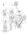
- FIG. 1 is a schematic view showing a brake system of a hybrid electric vehicle (HEV) of the front wheel drive to which a brake control system according to embodiments of the invention can be applied;
- HEV hybrid electric vehicle
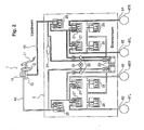
- FIG. 2 is a detailed schematic view showing a brake fluid pressure circuit including a VDC brake hydraulic pressure unit in the brake system according to a first embodiment of the invention
- FIG. 3 is a control block diagram showing a regenerative coordinate brake system according to the first embodiment
- FIG. 4 is a flow chart for setting a target deceleration characteristic map within a target deceleration characteristic map setting unit of a unified controller of FIG. 3 ;
- FIG. 5 is a flow chart showing regenerative coordinate brake control processes being performed by both a target deceleration calculation unit and a regenerative coordinate brake control unit of the unified controller of FIG. 3 ;
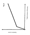
- FIG. 6 is a graph of a relationship between an operation current value applied to a differential pressure valve and a target difference pressure that is used for determination of a command value to obtain the add-on brake according to the first embodiment
- FIG. 7 is a graph of a control concept in accordance with a regenerative coordinate brake control system using a VDC, in which a target deceleration will be obtained by a sum total of a base brake hydraulic pressure, a regenerative brake portion and a pump-up pressure portion;
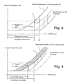
- FIG. 8 is a graph showing a regenerative coordinate brake operation of a comparative example of a HEV with the associated technical problem being illustrated when the actual master cylinder loss stroke is greater than designed;
- FIG. 9 is a view showing a regenerative coordinate brake operation for a comparative example of a HEV with the associated technical problem being illustrated when the actual master cylinder loss stroke is smaller than designed;
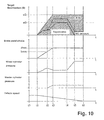
- FIG. 10 is a time chart showing an example of the regenerative coordinate brake control operation in which the HEV including the brake control system according to the first embodiment travels at a constant deceleration and comes to stop;
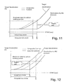
- FIG. 11 is a comparative analysis showing technical advantages realized by appropriately setting the target deceleration characteristic map for a brake control system according to the first embodiment when the actual master cylinder loss stroke is greater than designed;
- FIG. 12 is another comparative analysis showing technical advantages realized by appropriately setting the target deceleration characteristic map for a brake control system according to the first embodiment when the actual master cylinder loss stroke is smaller than designed;
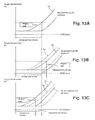
- FIGS. 13A, 13B and 13C are graphs of target deceleration characteristics wherein FIG. 13A shows a reference target deceleration characteristic, FIG. 13B shows a first target deceleration characteristic obtained by an offset of the reference target deceleration characteristic where the actual stroke is greater than designed, and FIG. 13C shows a second target deceleration characteristic obtained by an offset where the actual stroke is smaller than designed;
- FIG. 14 is a graph of target deceleration as a function of brake pedal stroke in a first example.
- FIG. 15 is a graph of target deceleration as a function of brake pedal stroke in a second example.
- FIG. 1 shows a system configuration of a hybrid electric vehicle (HEV) of a front wheel drive type to which a brake control system according to embodiments of the present invention can be applied.
- FIG. 2 illustrates a VDC brake system as an example of brake fluid pressure actuator.
- a brake deceleration generating mechanism of the brake control system includes a brake fluid pressure generating unit 1, a VDC brake fluid unit 2 (also called a brake fluid pressure actuator), a stroke sensor 3 for detecting a brake pedal stroke, wheel cylinders, specifically a left front wheel cylinder (4FL), a right front wheel cylinder (4FR), a left rear wheel cylinder (RL), and a right rear wheel cylinder (4RR), and an electric motor 5 for vehicle propulsion.
- a brake fluid pressure generating unit 1 includes a brake fluid pressure generating unit 1, a VDC brake fluid unit 2 (also called a brake fluid pressure actuator), a stroke sensor 3 for detecting a brake pedal stroke, wheel cylinders, specifically a left front wheel cylinder (4FL), a right front wheel cylinder (4FR), a left rear wheel cylinder (RL), and a right rear wheel cylinder (4RR), and an electric motor 5 for vehicle propulsion.
- a vehicle dynamics control (VDC) system is incorporated for a regenerative coordinate brake system.
- the VDC system generally copes with the disruption of vehicle behaviors such as entering a corner at high speed and/or quick manipulation of the steering wheel, avoids lateral slipping and provides a good running stability. For example, if the VDC control is implemented to a vehicle running in a corner where an oversteer tendency detected, a wheel at the front and corner outer side will be braked. When cornering behavior indicates an understeer tendency, vehicle propulsion power will be reduced and a wheel at the rear and inner side of the corner will be braked.
- Brake fluid pressure generating unit 1 generates a base brake fluid pressure in accordance with the driver's operation of a brake pedal. As shown in FIGS. 1 and 2 , the brake fluid pressure generating unit 1 includes a brake pedal 11, a vacuum booster 12, a master cylinder 13 and a reservoir tank 14. A brake pressure generated by the driver applying brake pedal 11 is amplified by vacuum booster 12, and a primary fluid pressure and a secondary fluid pressure will be generated by master cylinder 13.
- brake deceleration generated by master cylinder 13 should be set to be smaller than the target deceleration, i.e., a driver demand deceleration amount.
- VDC brake fluid pressure unit 2 is interposed between brake fluid pressure generating unit 1 and wheel cylinders 4FL, 4FR, 4RL and 4RR associated with respective wheels.
- VDC brake fluid pressure unit 2 is a brake fluid pressure actuator and has fluid pressure pumps 22 driven by a VDC motor 21, which is a dedicated electric motor.
- VDC brake fluid pressure unit 2 increases, maintains or reduces a pressure from master cylinder 13.
- VDC brake fluid pressure unit 2 and brake fluid pressure generating unit 1 are connected to each other via primary fluid conduit 61 and secondary fluid conduit 62.
- VDC brake fluid pressure unit 2 is connected to each wheel cylinder 4FL, 4FR, 4RL and 4RR through a left front wheel fluid conduit 63, a right front fluid conduit 64, a left rear wheel fluid conduit 65 and a right rear wheel fluid conduit 66, respectively. This way, when the driver applies brake pedal 11, a master cylinder pressure generated at brake fluid pressure generating unit 1 will further be raised by VDC fluid unit 2 and introduced into respective wheel cylinders 4FL, 4FR, 4RL, 4RR to exert a braking operation.
- VDC brake fluid generation unit 2 is detailed in FIG. 2 and has fluid pressure pumps 22 driven by VDC motor 21, reservoirs 23 and a master cylinder pressure sensor 24 for detecting an actual master cylinder pressure.
- Various solenoid valves are employed including a first master cylinder (M/C) cutoff solenoid valve 25 (e.g., a differential pressure valve), a second M/C cutoff solenoid valve 26 (e.g., a differential pressure valve), pressure holding solenoid valves 27 and pressure reduction solenoid valves 28.
- M/C cutoff solenoid valve 25 e.g., a differential pressure valve
- second M/C cutoff solenoid valve 26 e.g., a differential pressure valve
- pressure holding solenoid valves 27 e.g., a differential pressure valve
- pressure reduction solenoid valves 28 e.g., pressure reduction solenoid valves
- Brake pedal stroke sensor 3 is provided to detect an operation amount or stroke by a driver utilizing a potentiometer, for example. This stroke sensor 3 is intended to detect a target deceleration amount, i.e., a driver demand deceleration level, for use in regenerative coordinated brake control.
- a target deceleration amount i.e., a driver demand deceleration level
- Respective wheel cylinders 4FL, 4FR, 4RL, 4RR are each provided at an associated brake disk for front or rear wheels, and each is supplied with a controlled hydraulic pressure.
- brake rotors or disks are clamped by brake pads to apply a friction force therebetween, which in turn results in a hydraulic braking force to wheels.
- Electric motor 5 is provided as a driving source for driving wheels (left and right front wheels 4FL, 4FR in this example) and functions as both a driving motor and a generator. Electric motor 5 transfers a driving force or torque to the driving wheels when driven by energy from the battery. Moreover, in a regenerative mode, the motor applies load to left and right front wheels and thus recovers kinetic energy through regenerative braking to feed the battery.
- the driveline of the driving wheels can be further coupled to an internal combustion engine as another driving source with a transmission interposed in a HEV.
- the brake deceleration control system includes a brake controller 7, a motor controller 8 (also called a regenerative brake controller), a unified controller 9 and an engine controller 12. These controllers are connected with each other through a controller area network (CAN) or other on-vehicle local area network (LAN), and hence can mutually give and receive information.
- Unified controller 9 and the other controllers described herein generally consist of a respective microcomputer including central processing unit (CPU), input and output ports (I/O) receiving certain data described herein, random access memory (RAM), keep alive memory (KAM), a common data bus and read only memory (ROM) as an electronic storage medium for executable programs and certain stored values as discussed herein.
- controllers 7, 8, 9, 12 can each be an engine control unit (ECU) as known in the art programmed as described herein. Further, although multiple controllers 7, 8, 9, 12 are shown, the functions of each can be included or programmed into fewer or more controllers.
- ECU engine control unit
- Brake controller 7 receives a command signal from unified controller 9 and pressure indicative information from master cylinder pressure sensor 24 of VDC brake fluid pressure unit 2. Then, based on predetermined control logic, brake controller 7 outputs drive command signals to both VDC motor 21 of VDC brake fluid pressure unit 2 and the plurality of solenoid valves 25, 26, 27 and 28. During regenerative braking control operations, brake controller 7 adjusts a pressure difference between the wheel cylinder pressure and the master cylinder pressure in response to receipt of a pump-up pressure command from unified controller 9. This pressure differentiating control is performed by operation current applied to both first M/C cutoff solenoid valve 25 and second M/C cutoff solenoid valve 26 on the one hand, and by a pump-up pressure increase by VDC motor 21 on the other.
- brake controller 7 performs other control, such as VDC control, traction control system (TCS) control and anti-lock braking system (ABS) control, in addition to regenerative braking control.
- Motor controller 8 is connected via an inverter (INV) 13 to electric motor 5 for vehicle propulsion. During a regenerative braking operation, the regenerative power generated by electric motor 5 will be controlled by motor controller 8 based on a regenerative braking portion command from unified controller 9. Motor controller 8 also functions to control, during vehicle travelling, a motor torque or revolution speed of electric motor 5 depending on running conditions and vehicle conditions.
- ISV inverter
- Unified controller 9 performs regenerative coordinate brake control and attains a target deceleration during brake application by summing a master cylinder pressure-based braking (also called a base brake fluid pressure portion) and an add-on braking portion.
- the add-on braking portion is at least one of a regenerative braking portion supplied by brake controller 7 and a pump-up pressure portion supplied by VCD brake pressure unit 2.
- the target deceleration is determined based on a detected brake pedal stroke or position from stroke sensor 3 and a previously defined target deceleration characteristic map.
- various input signals are input including battery state-of-charge information from battery controller 91, vehicle speed related information from a vehicle speed sensor 92, the brake actuation stroke signal from stroke sensor 3 and master cylinder pressure information from master cylinder pressure sensor 24.
- the vehicle speed sensor 92 may preferably be a wheel rotational speed sensor to detect the vehicle speed down to a significantly low vehicle speed.
- Unified controller 9 includes a reference map setting unit 9a (also called a reference brake target characteristic map setting unit), a target deceleration characteristic map setting unit 9b (also called a braking target characteristic map setting unit), a target deceleration calculating unit 9c and a regenerative coordinate brake control unit 9d.
- Reference map setting unit 9a determines a designed master cylinder pressure generating point of the brake pedal stroke position based on a previously estimated loss stroke of brake pedal 11. Based on this designed stroke, a reference target deceleration characteristic map as compared to a pedal stroke position is previously set and stored. This map is also called a reference target brake characteristic map.
- Target deceleration characteristic map setting unit 9b receives signals indicative of the brake pedal stroke position and the master cylinder pressure and, based on these signals, detects an actual master cylinder pressure generating point at a given brake pedal stroke position with an offset stroke distance representing a difference of the given brake pedal stroke position from the referenced or designed brake pedal position. Then, the reference deceleration characteristic is read from reference map setting unit 9a and shifted by the offset stroke distance in such a way that an add-on value for brake deceleration will be maximized and becomes the regenerative gap at the actual master cylinder pressure generating point of brake pedal 11.
- Target deceleration calculating unit 9c calculates a target deceleration, also called a driver demand total amount of deceleration or brake target force, based on the target deceleration characteristic from the target deceleration characteristic map set at target deceleration characteristic map setting unit 9b and the brake pedal stroke position detected by stroke sensor 3.
- a target deceleration also called a driver demand total amount of deceleration or brake target force
- Regenerative coordinate brake control unit 9d receives the target deceleration calculated at target deceleration calculating unit 9c, the master cylinder pressure from master cylinder pressure sensor 24, and the vehicle speed from vehicle speed sensor 92. It then determines a base brake fluid pressure portion based on the master cylinder pressure and a regenerative braking portion based on the vehicle speed and tries to achieve the target total braking deceleration using the base brake fluid pressure portion and regenerative braking portion so as to obtain a high recuperation rate of braking energy. In the event, however, that a shortage would occur and these two portions would not satisfy the target braking demand, then the shortage will be supplemented by a pump-up pressure portion. Based on these calculations, unified controller 9 sends a command signal for the regenerative portion to motor controller 8 and a command signal indicative of the pump-up pressure portion to brake controller 7.
- FIG. 4 a flow chart of control for setting a target deceleration characteristic map that is prepared by target deceleration characteristic map setting unit 9b is shown.
- This control routine may be initiated off-line after the brake control components have been assembled at a factory or dealership.
- the routine may be initiated each time the engine is started by an ignition switch and/or vehicle start button for a HEV, fuel cell or electric vehicle and a brake pedal is subsequently operated by a driver.
- step S1 master cylinder pressure information from master cylinder pressure sensor 24 and brake pedal stroke information from brake stroke sensor 3 are read, and control proceeds to step S2.
- step S2 based on a switch signal from brake switch 93 it is decided whether or not the driver applies brake pedal 11. If so (brake pedal 11 is applied), the control goes to step S3, and if not (brake pedal 11 is being not applied), then control returns.
- step S3 subsequent to an affirmative decision at step S2, a decision is made as to whether a master cylinder pressure is generated in response to the brake pedal operation. If a master cylinder pressure is actually generated, the control proceeds to step S4. If a master cylinder pressure is not yet detected, the control returns.
- step S4 subsequent to the decision in step S3 that the master cylinder generates an actual pressure, the point or position of the brake pedal stroke at which the actual master cylinder pressure is generated is stored as an actual master cylinder pressure generating point in memory of unified controller 9, and control proceeds to step S5.
- a target value for the add-on brake portion for braking deceleration is maximized at the stored pedal stroke position representing the actual master cylinder pressure generating point, and a gradual, preferably non-linear, target deceleration characteristic profile or curve is stored as a target deceleration characteristic map. Then, control returns.
- a brake depressing velocity may preferably be incorporated. The brake pedal depressing velocity is generally calculated by the difference in brake pedal positions detected at each control cycle.
- FIG. 5 a flow chart showing a regenerative coordinate brake control process performed by both target deceleration calculation unit 9c and regenerative coordinate brake control unit 9d is now described.
- the regenerative coordinate brake control process starts upon brake pedal 11 being operated by a vehicle driver.
- VDC motor 21 is set to a driven state from a stopped state it is in before the brake pedal operation, and control goes to step S22.
- step S22 a master cylinder pressure from master cylinder sensor 24, a pedal stroke from stroke sensor 3, a vehicle speed from vehicle speed sensor 92 and the target deceleration characteristic map set at step S5 of FIG. 4 are read, and control proceeds to step S23.
- a brake pedal depressing velocity is calculated and the target deceleration characteristic is adjusted depending on the brake pedal depressing velocity. It is appreciated here that adjustment of the target deceleration characteristic will be made when the previously estimated or designed brake depressing velocity for a previously set target deceleration characteristic becomes different from that calculated. More specifically, when the calculated brake pedal depressing velocity is faster than that previously designed, calculated or estimated, an offsetting of the target deceleration characteristic will be made such that the loss stroke to the actual master cylinder pressure generating point will be set smaller. When the calculated pedal depressing velocity lies within a permissible tolerance range of a previous value, there is no need for adjustment of the target deceleration characteristic.
- step S24 subsequent to the optional adjustment of the target deceleration characteristic based on brake pedal depressing velocity in step S23, a final target deceleration characteristic is prepared over various brake pedal stroke positions. Control then proceeds to step S25.
- a base brake fluid pressure portion is detected based on the master cylinder pressure read in step S22. Then, a maximum regenerative amount available is determined based on the vehicle speed and the state of charge of the battery and is designated as a regenerative braking portion. After subtracting the base brake fluid pressure portion and the regenerative braking portion from the total target for deceleration amount, the remainder is desirably allocated to the pump-up pressure portion. In other words, the sum total of a basic brake pressure portion, a regenerative brake portion and a pump-up pressure portion meet the driver's intent for the desired amount of deceleration indicated by input to brake pedal 11. The regenerative coordinate brake control then goes to step S26.
- step S26 allocation of the target add-on brake force, i.e., the amount of deceleration not covered by the base brake fluid pressure portion, is made. Specifically, a command signal indicative of the regenerative brake portion (even if no demand is requested)is sent to motor controller 8. At the same time, a command signal indicative of the pump-up pressure portion (even if no demand is requested) is sent to brake controller 7. Then, control proceeds to step S27.
- motor controller 8 determines upon receipt of the regenerative command a regenerative portion as the target regenerative brake force and performs regenerative torque control by feed-forward controlling electric motor 8 to determine regenerative current.
- Brake controller 7 determines, upon receipt of the pump-up pressure command, a pump-up pressure portion as a target pressure difference, and, referring to the relationship between target pressure difference and operative current as shown by example in FIG. 6 , feed-forward controls M/C cutoff solenoid valves 25, 26 by applying the necessary operating current to obtain the required pressure difference.
- step S27 subsequent to output of the regenerative brake command and the pump-up pressure command at step S26, it is determined whether or not the vehicle comes to stop based on vehicle speed from vehicle speed sensor 92. If the vehicle is stopped, then control proceeds to step S28. In contrast, if the vehicle is still in motion, then control returns to step S22.
- step S27 If the vehicle is stopped at step S27, operation of VDC motor 21 stopped at step S28, and the process comes to end.
- Regenerative coordinate braking control using a VDC is directed to supplementing the brake fluid pressure needed to meet a driver's demand for the necessary deceleration that cannot be met by a base brake pressure portion and a regenerative brake portion alone.
- the supplemental brake fluid pressure is obtained by using a VDC brake pressure unit. The overall operation of this regenerative coordinate brake system using the VDC is now explained with reference to FIG. 7 .
- a base brake fluid pressure generated thereby and amplified by a vacuum booster is designed to equal the driver demand target deceleration.
- the system intentionally reduces the available brake fluid pressure to produce a shortage to the desired deceleration, resulting in a so-called regenerative gap between the base brake fluid pressure and the required total brake force. Attempt has been made so that this regenerative gap is maximized where efficiency is a priority.
- the total amount of braking deceleration is basically designed to be supplied by the sum of the base brake fluid pressure portion from the vacuum booster and the regenerative portion from the regenerative brake. Only when these two would not be enough to meet the total demand would the shortage be covered by the VDC brake fluid unit (as a pump-up pressure portion). This is shown in FIG. 9 .
- a hypothetical comparative example is illustrated where the target deceleration is set to match the amount of the regenerative gap at a designed master cylinder pressure generating point with loss stroke position B, and a target deceleration characteristic curve is defined to change gradually with respect to a change in the brake pedal stroke.
- the stroke position reaching the designed loss stroke value corresponds to the designed master cylinder pressure generating point at which a master cylinder pressure is designed to start to generate in the nominal designed model.
- the expression "regenerative gap” denotes a difference between the target deceleration and the base brake fluid pressure portion caused by the M/C pressure. This difference is fulfilled by the maximum amount of pressure available from the regenerative brake, and thus is named the regenerative gap.
- FIG. 8 is used to describe the situation in which the actual master cylinder pressure generating point B (hereinafter referred to "point B") is delayed as compared to the designed master cylinder fluid pressure generating point A (hereinafter simply "point A").
- the deceleration characteristic (Target G) is targeted such that the basic brake fluid pressure portion (where the amount is zero) is added to the regenerative gap, and thus the target deceleration will be obtained by the regenerative gap.
- the characteristic value at point B of the brake pedal stroke, reached later than point A is obtained when the value at point A is combined with an increased amount of base brake fluid pressure amount to be expected.
- the base fluid pressure portion remains zero. Therefore, a target deceleration is obtained by the regenerative gap only.
- the target deceleration characteristic as the brake pedal stroke advances will be constant from point A to B as shown by the encircled area designated D. Accordingly, the target deceleration will not rise despite the indication by the driver of the need to increase the target deceleration as the brake pedal stroke advances.
- FIG. 9 demonstrates a situation in which the actual master cylinder generation point C (hereinafter point C) advances earlier than the designed master cylinder pressure generating point A.
- the characteristic value (Target G) at point C of brake pedal travel is determined by adding a value less than the regenerative gap to the base fluid pressure portion, which assumes a value of zero.
- the resulting deceleration level obtained is less than the regenerative gap.
- the deceleration characteristic increases gradually and becomes the total sum of the basic brake fluid pressure portion plus the regenerative gap so that the target deceleration level corresponds to the regenerative gap.
- the regenerative brake portion is set smaller than the regenerative gap.
- the target deceleration characteristic increases in response to an earlier generation of the base brake fluid pressure, with the add-on brake portion maintained at a value less than the regenerative gap.
- the hatching portion illustrated by region E in FIG. 9 is regarded as a regenerative braking restriction region. Therefore, although the target deceleration characteristic is obtained with a gradual change over pedal stroke, the regenerative torque is restricted over the entire brake stroke travel. As a result, the fuel consumption efficiency deteriorates for a HEV, and electrical economy goes down for an electric vehicle.
- control begins at step S21, and then proceeds through step S22 to step S27.
- step S27 as long as the vehicle remains at stand-still condition, control proceeds to step S28, and the program of regenerative coordinate braking control ends.
- the target deceleration corresponding to the brake pedal stroke by driver actuation is calculated at step S24.
- a base brake fluid pressure portion is determined based on the sensed master cylinder pressure together with a possibly recoverable maximum regenerative energy portion based on the vehicle speed and state of charge of the battery.
- the remaining deceleration portion obtainable by subtracting the base brake fluid pressure portion and the regenerative brake portion from the target deceleration is assigned to the pump-up pressure portion, which is realized by brake controller 7.
- the regenerative brake corresponding portion is sent as a regenerative portion command (even if a zero command) to motor controller 8, while the pump-up pressure portion is sent as a pump-up command (even if a zero add-on command) to brake controller 7.
- motor controller 8 receives the regenerative portion command and, based on the required target regenerative braking, determines a regenerative current value for the electric motor 5 and feed-forward controls the regenerative torque.
- Brake controller 7 that receives the pump-up pressure command, sets the pump-up pressure as a target difference pressure, and controls VDC motor 21 to increase revolution while determining the operative current to both M/C cutoff solenoid valves 25, 26 for controlling the pressure difference via feed-forward control using a relationshipsuch as shown in FIG. 6 .
- the vehicle maintains a constant vehicle speed, and upon brake pedal operation, the target deceleration amount will increase from zero G (at t1) to aG (at t2).
- the target deceleration is obtained by increasing the regenerative portion and the pump-up portion (VDC_P/U), leading to a pressure increase to the wheel cylinder pressure. Since brake pedal 11 is within the region of loss stroke (brake pedal stroke is between 0 mm through b mm), no master cylinder pressure is generated.
- target deceleration increases from aG to cG. This target deceleration is achieved by appropriately allocating the base brake fluid pressure portion due to increase of the master cylinder pressure, increasing the regenerative brake portion and decreasing the pump-up pressure portion (VDC_P/U).
- the target deceleration is also held constant at cG until a time point t4 at which the regenerative portion is restricted.
- the target deceleration amount is achieved by a base brake fluid pressure portion from a constant master cylinder pressure, a permissible maximum level of the regenerative portion and a constant pump-up portion, leading to a constant wheel cylinder pressure.
- the target deceleration amount is maintained at cG.
- the target deceleration is achieved by the base brake fluid pressure portion resulting from a constant master cylinder pressure, a decreasing regenerative portion and an increasing pump-up pressure portion (VDC_P/U).
- the regenerative portion becomes zero at time point t5. From this time point t5 to time point t6 at which the vehicle stops, the target deceleration level is maintained at constant value cG.
- the target deceleration is achieved by the base brake fluid pressure portion of the constant master cylinder pressure and the add-on portion due to a constant wheel cylinder pressure.
- VDC_P/U add-on portion
- step S4 the pedal stroke position at which master cylinder pressure actually generates is stored in memory as the actual master cylinder pressure generating point.
- the add-on target deceleration amount is set to be maximized at the actual master cylinder pressure generating point, and a target deceleration characteristic with a gradual change over a range of brake pedal stroke is defined as the target deceleration characteristic map.
- a brake pedal stroke is first sensed to confirm the point at which a master cylinder pressure actually generates. Then, the target deceleration at this confirmed actual point is set to be a maximum of the add-on target braking force to be added to the base brake fluid pressure portion. Since at this point there is no base brake fluid pressure generated, the target deceleration approximately corresponds to the regenerative gap.
- the add-on target value for deceleration is set to be a maximum of an add-on target braking force, i.e., the regenerative gap.
- the regenerative gap As will be illustrated in FIGS. 11 and 12 , with the regenerative gap as a maximum add-on target braking force, a reference target characteristic profile is shifted toward the actual master cylinder generating points B, C from the designed point A.
- the target deceleration characteristic changes gradually over brake pedal stroke as shown in solid lines.
- a target deceleration characteristic is set to gradually change over the entire stroke of brake pedal 11. More specifically, from zero stroke to point B, a gradual rising curve to meet the regenerative gap at point B is defined. Thereafter, in accordance with the deceleration characteristic accorded by the master cylinder pressure, the characteristic curve rises while maintaining a constant difference of the regenerative gap. As shown in FIG. 11 with broken lines, the comparative example exhibits a suppression of an increase in braking force despite the progress of brake pedal stroke travel between point A and point B. In contrast and in accordance with the teachings herein, the target deceleration increases gradually during the brake stroke region between point A and B. Thus, a comfortable brake pedal feel is assured without uneven pedal feel.
- the braking target characteristic changes gradually over the entire pedal stroke travel range. Specifically, from a zero stroke point to point C, a characteristic curve is set to gradually rise up to the regenerative gap. For the stroke region in excess of point C, the curve rises further in accordance with the progress of the brake pedal stroke while maintaining a constant regenerative portion, i.e., the regenerative gap.
- a target deceleration characteristic (broken lines) in which the target deceleration is suppressed over the entire pedal stroke travel exists.
- the target deceleration characteristic curve increases for a region before point C and maintains the regenerative gap as an add-on braking force after point C. This assures a high level of energy recovery for improving vehicle efficiency.
- the deceleration force corresponding to the regenerative gap is placed on the characteristic profile or curve, and the target deceleration characteristic is defined to take a gradual change over the range of brake pedal stroke travel. Due to this arrangement, change in the actual master cylinder pressure points caused by mechanical tolerances will not influence the target deceleration. Therefore, during the regenerative coordinate brake control operation, setting a target deceleration by excluding the influence of the master cylinder pressure generating point will result in a more comfortable brake operation as well as securing a high level of regenerative energy.
- a methodology to set a target deceleration characteristic by an off-set adjustment is now described.
- a designed point of brake pedal stroke A is determined, based on the designed loss-stroke, at which master cylinder pressure is estimated to begin to be generated.
- a reference map containing a reference target deceleration characteristic Ga that assumes a maximum value for an add-on target braking force at the designed point A as the regenerative gap is developed.
- actual master cylinder pressure generating point B or C of the brake pedal stroke position is detected based on the sensed pedal stroke position and master cylinder pressure sensor at target deceleration characteristic map setting unit 9b.
- the add-on braking force is maximized to take the value for the regenerative gap at the detected point B.
- the reference target deceleration characteristic Ga read from reference map setting unit 9a is shifted or offset in the stroke increasing direction to define an adjusted target deceleration characteristic Gb.
- the add-on braking force is maximized to take the value for the regenerative gap at the detected point C.
- the reference target deceleration characteristic Ga read from reference map setting unit 9a is shifted or off-set in the stroke decreasing direction to define an adjusted target deceleration characteristic Gc.
- the reference target deceleration characteristic Ga is previously stored, and subsequently the reference target deceleration characteristic Ga is adjusted by offsetting to define target deceleration characteristic Gb or target deceleration characteristic Gc.
- step S23 brake pedal depressing velocity is calculated, and adjustment of the target deceleration map in consideration of pedal depressing velocity is performed. This adjustment is made if the pedal velocity related information included in the preset target deceleration characteristic map and the depressing velocity calculated at step 23 are different.
- the rationale behind the adjustment by pedal depressing velocity resides in that the timing of the actual master cylinder pressure generating point gets earlier as the pedal depressing velocity gets faster, and the actual master cylinder pressure generating points will move in the shorter direction of brake pedal stroke.
- Such an off-set distance should be considered in implementing the off-set adjustments of the target deceleration characteristic.
- the adjustment of the target deceleration characteristic map is made reflecting the pedal depressing velocity in the following manner. If the calculated depressing velocity is larger than the presupposed depressing velocity of brake pedal 11 reflected in the target deceleration characteristic Gb, then the loss stroke travel to the actual master cylinder pressure generating point B is set shorter and off-set in the left direction in FIG. 14 , and an adjusted target deceleration characteristic Gb' is obtained.
- the adjustment of the target deceleration characteristic map is made reflecting the pedal depressing velocity in the following manner. If the calculated depressing velocity is larger than the presupposed depressing velocity of brake pedal 11 reflected in the target deceleration characteristic Gc, then the loss stroke travel to the actual master cylinder pressure generating point C is set shorter and off-set in the left direction in FIG. 15 , and an adjusted target deceleration characteristic Gc' is obtained.
- brake pedal depressing velocity can also be calculated so that the target deceleration characteristic map is set reflecting the actual pedal depressing velocity.
- the target deceleration characteristic map excluding influences of mechanical tolerance may be further modified to eliminate the influence caused by the brake pedal depressing velocity. Therefore, during regenerative coordinate braking, the target deceleration characteristic map excluding influences by mechanical tolerances may be further tailored to eliminate the influences of the pedal depressing speed.
- the braking target characteristic (target deceleration characteristic Gb, Gc) compensating for changes in master cylinder pressure generating points may be easily obtained by way of off-setting of the reference braking target characteristic (reference target deceleration characteristic Ga).
- a target deceleration map against brake pedal stroke is shown as the braking target characteristic map.
- other alternatives may be employed such as a target braking force or torque map against the driver brake pedal stroke, driver demand deceleration map against brake pedal stroke or demand brake force map against brake pedal stroke.
- a target deceleration characteristic may be calculated on a real time basis. In sum, during brake pedal operation, as long as the braking target characteristic is obtained reflecting a driver braking performance demand, use of a map containing a characteristic curve is not required, but a characteristic value may be calculated or modified based on the characteristic equations reflected in the characteristic map.
- the deceleration characteristic has been defined herein in such a way that the target deceleration at the detected, actual master cylinder generating point assumes a maximum of the add-on braking portion (i.e., the regenerative gap), and the target deceleration characteristic varies gradually over the change in brake pedal stroke.
- the difference between the target deceleration value at the actual point and the maximum value for add-on braking (regenerative gap) may be within a tolerable range.
- the target deceleration characteristic map is set by an off-set adjustment of the reference target deceleration characteristic map.
- the inclination angle of the reference target deceleration characteristic curve may be changed to set the target deceleration characteristic.
- the target deceleration may be calculated to assume a maximum add-on portion (regenerative gap) at the detected actual master cylinder pressure generating point. More specifically, the target deceleration characteristic G according to FIGS.
- the target deceleration may be set at the actual master cylinder pressure generating point or timing to assume the maximum value for an add-on braking, preferably by way of regenerative braking irrespective of use of map or real time calculation.
- the actual master cylinder pressure generating point may be adjusted by learning control based on the various data obtained through brake control experiences.
- the target deceleration map may be set or tuned either at the off-line testing or setting station after brake control components have been installed on vehicle in the car assembly line or at a dealership, or at the first brake operation timing each time an ignition or start switch has been turned on by a driver.
- a map adjustment methodology is explained to compensate for brake pedal depressing velocity.
- the target deceleration characteristic map containing a presupposed, reference brake depressing velocity at the master cylinder pressure generating point is adjusted by off-setting in accordance with the detected depressing velocity. If memory capacity in the target deceleration characteristic map setting unit would not pose a problem, a plurality of target deceleration characteristics may be prepared against a plurality of brake depressing speeds so that, depending on the actual braking speed detected, the best map out of the plurality of target deceleration characteristic maps may be read and applied.
- VDC brake fluid unit 2 as shown in FIG. 2 is utilized as a brake fluid actuator.
- the brake fluid pressure actuator it is sufficient to provide a fluid pressure pump driven by VDC motor and a differential pressure valve for controlling the pressure difference between the wheel cylinder pressure and master cylinder pressure during operation of the pump motor.
- the entirety of unit 2 shown in FIG. 2 is not required.
- the brake control system is applied to a HEV with front wheel drive.
- the present invention may also be applicable to a HEV with rear wheel drive, an electric vehicle, a fuel cell vehicle and other electrically driven vehicles.
Applications Claiming Priority (1)
| Application Number | Priority Date | Filing Date | Title |
|---|---|---|---|
| JP2010270185A JP5691453B2 (ja) | 2010-12-03 | 2010-12-03 | 電動車両のブレーキ制御装置 |
Publications (3)
| Publication Number | Publication Date |
|---|---|
| EP2460701A2 true EP2460701A2 (fr) | 2012-06-06 |
| EP2460701A3 EP2460701A3 (fr) | 2013-06-19 |
| EP2460701B1 EP2460701B1 (fr) | 2016-03-16 |
Family
ID=45688369
Family Applications (1)
| Application Number | Title | Priority Date | Filing Date |
|---|---|---|---|
| EP11007487.9A Active EP2460701B1 (fr) | 2010-12-03 | 2011-09-14 | Système de commande de frein pour véhicule électrique |
Country Status (4)
| Country | Link |
|---|---|
| US (1) | US8523297B2 (fr) |
| EP (1) | EP2460701B1 (fr) |
| JP (1) | JP5691453B2 (fr) |
| CN (1) | CN102529926B (fr) |
Cited By (9)
| Publication number | Priority date | Publication date | Assignee | Title |
|---|---|---|---|---|
| WO2014095283A1 (fr) * | 2012-12-21 | 2014-06-26 | Lucas Automotive Gmbh | Système de freinage électrohydraulique pour véhicule et procédé de fonctionnement |
| WO2015015081A1 (fr) * | 2013-07-30 | 2015-02-05 | Renault S.A.S | Controle du freinage pour un vehicule equipe d'un moyen de freinage regeneratif |
| EP2889197A1 (fr) * | 2013-12-26 | 2015-07-01 | Nissin Kogyo Co., Ltd. | Système de frein |
| US9499141B1 (en) | 2015-09-29 | 2016-11-22 | Faraday & Future Inc. | Sensor-triggering of friction and regenerative braking |
| US10464536B2 (en) | 2016-11-11 | 2019-11-05 | Honda Motor Co., Ltd. | Adaptive vehicle braking systems, and methods of use and manufacture thereof |
| CN110758358A (zh) * | 2019-10-30 | 2020-02-07 | 北京理工大学 | 一种履带车辆机电联合制动控制方法及装置 |
| CN111806241A (zh) * | 2020-06-28 | 2020-10-23 | 同济大学 | 一种轨道交通列车再生电能回收空间确定方法 |
| CN112441000A (zh) * | 2019-08-16 | 2021-03-05 | 华为技术有限公司 | 一种车辆制动的控制方法和装置 |
| IT202000030368A1 (it) * | 2020-12-10 | 2022-06-10 | Brembo Spa | Metodo di controllo della decelerazione di un veicolo, sistema frenante |
Families Citing this family (34)
| Publication number | Priority date | Publication date | Assignee | Title |
|---|---|---|---|---|
| US8998352B2 (en) * | 2010-11-08 | 2015-04-07 | Nissan Motor Co., Ltd. | Vehicle brake control device for an electrically driven vehicle |
| DE102011054290B4 (de) * | 2011-10-07 | 2024-05-08 | Dr. Ing. H.C. F. Porsche Aktiengesellschaft | Verfahren und Vorrichtung zum Steuern eines Bremssystems für ein Kraftfahrzeug mit einer Bremseinrichtung |
| KR101428253B1 (ko) | 2012-12-07 | 2014-08-07 | 현대자동차주식회사 | 차량의 제동 제어 방법 |
| DE102012222978A1 (de) * | 2012-12-12 | 2014-06-12 | Robert Bosch Gmbh | Verfahren zum Betreiben eines Bremssystems eines Fahrzeugs und Steuervorrichtung für ein Bremssystem eines Fahrzeugs |
| CN104995069B (zh) * | 2013-02-15 | 2016-10-12 | 日产自动车株式会社 | 车辆用制动装置 |
| EP2960122B1 (fr) * | 2013-02-19 | 2018-02-14 | Mitsubishi Electric Corporation | Dispositif de commande de frein |
| JP6112303B2 (ja) * | 2013-10-31 | 2017-04-12 | マツダ株式会社 | 車両用挙動制御装置 |
| CN103802825A (zh) * | 2014-01-24 | 2014-05-21 | 新昌县冠阳技术开发有限公司 | 一种混合动力车辆控制装置 |
| CN103754217A (zh) * | 2014-01-24 | 2014-04-30 | 新昌县冠阳技术开发有限公司 | 一种混合动力车辆控制方法 |
| GB201411228D0 (en) * | 2014-06-24 | 2014-08-06 | Torotrak Dev Ltd | Driver interface for a kinetic energy recovery system |
| KR102286743B1 (ko) * | 2014-11-05 | 2021-08-09 | 현대모비스 주식회사 | 차량용 회생제동 시스템 제어 방법 |
| US10011255B2 (en) * | 2014-11-07 | 2018-07-03 | Honda Motor Co., Ltd. | Vehicle brake system and vehicle brake system control method |
| KR101704176B1 (ko) * | 2015-03-23 | 2017-02-07 | 현대자동차주식회사 | 하이브리드 차량의 제동 제어 방법 |
| US20180065611A1 (en) * | 2015-03-31 | 2018-03-08 | Hitachi Automotive Systems, Ltd. | Brake control device and control method |
| US20170130748A1 (en) * | 2015-11-05 | 2017-05-11 | Borgwarner Inc. | Multi-output charging device |
| JP6520874B2 (ja) * | 2016-09-12 | 2019-05-29 | トヨタ自動車株式会社 | 車両制御装置 |
| JP6466892B2 (ja) * | 2016-10-20 | 2019-02-06 | 株式会社Subaru | プラグインハイブリッド車両の制御装置 |
| KR102417509B1 (ko) * | 2016-11-22 | 2022-07-05 | 현대자동차주식회사 | 회생제동 협조제어 시 제동 제어 방법 |
| CN106828119B (zh) * | 2017-01-11 | 2018-12-18 | 电子科技大学 | 一种兼顾回馈效率与制动效能的制动系统及制动方法 |
| CN108656956B (zh) * | 2017-03-27 | 2022-09-23 | 杭州长江汽车有限公司 | 电动汽车制动方法、系统及电动汽车 |
| CN106864273B (zh) * | 2017-04-01 | 2019-08-13 | 广州汽车集团股份有限公司 | 制动能量回收值确定方法和装置、及能量回收系统和方法 |
| CN107139897B (zh) * | 2017-04-28 | 2020-05-22 | 苏州银雀智能科技有限公司 | 一种新能源汽车的刹车系统、能量回收装置、新能源汽车 |
| DE102017111077A1 (de) | 2017-05-22 | 2018-11-22 | Lsp Innovative Automotive Systems Gmbh | Bremsvorrichtung, insbesondere für elektrisch angetriebene Kraftfahrzeuge |
| DE102017214602A1 (de) * | 2017-08-22 | 2019-02-28 | Robert Bosch Gmbh | Steuervorrichtung und Verfahren zum Betreiben einer Fahrzeugverzögerungsvorrichtung eines Fahrzeugs |
| KR102006827B1 (ko) * | 2017-09-26 | 2019-10-01 | 주식회사 만도 | 전자식 브레이크 시스템 및 그 제어 방법 |
| WO2019221554A1 (fr) * | 2018-05-17 | 2019-11-21 | 주식회사 만도 | Système de frein |
| CN109101689B (zh) * | 2018-07-06 | 2023-01-31 | 同济大学 | 一种基于车辆行为调整模型的用于最佳跟驰车距计算的曲线拟合建模方法 |
| KR102492488B1 (ko) * | 2018-10-22 | 2023-01-27 | 현대모비스 주식회사 | 차량의 제동 제어 장치 및 방법 |
| DE112020002307T5 (de) | 2019-05-09 | 2022-02-17 | Cts Corporation | Fahrzeugbremspedal mit pedalwiderstandsbaugruppe und kraft-/positionssensor |
| US11498428B2 (en) | 2019-10-28 | 2022-11-15 | Caterpillar Inc. | Directional shift variable brake disengagement |
| KR20210076489A (ko) * | 2019-12-16 | 2021-06-24 | 현대자동차주식회사 | 전기자동차의 회생제동토크 제어 장치 및 그 방법 |
| CN114802165B (zh) * | 2022-05-05 | 2023-02-10 | 江铃汽车股份有限公司 | 车辆的制动方法、装置、设备及存储介质 |
| DE102022205840A1 (de) * | 2022-06-08 | 2023-12-14 | Robert Bosch Gesellschaft mit beschränkter Haftung | Steuervorrichtung und Verfahren zum Betreiben eines rekuperativen Bremssystems eines Fahrzeugs |
| CN116968705B (zh) * | 2023-09-22 | 2023-12-08 | 北京车道线科技有限公司 | 复合制动中电机回馈制动扭矩补偿方法、装置及存储介质 |
Citations (1)
| Publication number | Priority date | Publication date | Assignee | Title |
|---|---|---|---|---|
| JP2006096218A (ja) | 2004-09-30 | 2006-04-13 | Advics:Kk | 車両用ブレーキ装置 |
Family Cites Families (17)
| Publication number | Priority date | Publication date | Assignee | Title |
|---|---|---|---|---|
| JPH06253406A (ja) * | 1993-02-26 | 1994-09-09 | Mitsubishi Electric Corp | 電気自動車用制動装置 |
| JP3565353B2 (ja) * | 1994-07-13 | 2004-09-15 | 株式会社ボッシュオートモーティブシステム | 回生ブレーキ連動摩擦ブレーキシステム |
| JPH11301434A (ja) | 1998-04-16 | 1999-11-02 | Toyota Motor Corp | 車輌の制動力制御装置 |
| JP2003284202A (ja) * | 2002-03-25 | 2003-10-03 | Toyota Motor Corp | 制動トルク制御装置 |
| JP4147976B2 (ja) * | 2002-09-13 | 2008-09-10 | 日産自動車株式会社 | 複合ブレーキの協調制御装置 |
| US20050269875A1 (en) * | 2004-06-08 | 2005-12-08 | Kazuya Maki | Vehicle brake device |
| JP2007030631A (ja) * | 2005-07-25 | 2007-02-08 | Advics:Kk | 車両用ブレーキ制御装置 |
| JP4775078B2 (ja) * | 2006-04-03 | 2011-09-21 | 株式会社アドヴィックス | 車両用ブレーキ制御装置 |
| US8366210B2 (en) * | 2006-04-03 | 2013-02-05 | Advics Co., Ltd. | Braking apparatus for vehicle |
| KR20080051492A (ko) * | 2006-12-06 | 2008-06-11 | 현대자동차주식회사 | 전기자동차용 회생제동 제어 방법 |
| JP5074877B2 (ja) * | 2007-10-12 | 2012-11-14 | 日立オートモティブシステムズ株式会社 | ブレーキ倍力制御装置 |
| JP5036490B2 (ja) | 2007-10-31 | 2012-09-26 | トヨタ自動車株式会社 | ブレーキ制御装置 |
| FR2923422B1 (fr) | 2007-11-14 | 2010-05-14 | Renault Sas | Procede de controle du freinage recuperatif d'un vehicule comprenant au moins un moteur electrique |
| JP5107075B2 (ja) * | 2008-01-31 | 2012-12-26 | トヨタ自動車株式会社 | 制動装置 |
| JP4712833B2 (ja) * | 2008-06-25 | 2011-06-29 | 日立オートモティブシステムズ株式会社 | ブレーキ制御装置およびその制御方法 |
| JP5396853B2 (ja) * | 2008-12-25 | 2014-01-22 | 日産自動車株式会社 | ハイブリッド車両の回生制動力制御装置及び回生制動力制御方法 |
| JP5304274B2 (ja) * | 2009-01-29 | 2013-10-02 | 日産自動車株式会社 | 車両用制動制御装置 |
-
2010
- 2010-12-03 JP JP2010270185A patent/JP5691453B2/ja active Active
-
2011
- 2011-09-07 US US13/226,903 patent/US8523297B2/en active Active
- 2011-09-14 EP EP11007487.9A patent/EP2460701B1/fr active Active
- 2011-12-05 CN CN201110399337.0A patent/CN102529926B/zh active Active
Patent Citations (1)
| Publication number | Priority date | Publication date | Assignee | Title |
|---|---|---|---|---|
| JP2006096218A (ja) | 2004-09-30 | 2006-04-13 | Advics:Kk | 車両用ブレーキ装置 |
Cited By (16)
| Publication number | Priority date | Publication date | Assignee | Title |
|---|---|---|---|---|
| US9616870B2 (en) | 2012-12-21 | 2017-04-11 | Lucas Automotive Gmbh | Electrohydraulic motor vehicle brake system and method for operating the same |
| WO2014095283A1 (fr) * | 2012-12-21 | 2014-06-26 | Lucas Automotive Gmbh | Système de freinage électrohydraulique pour véhicule et procédé de fonctionnement |
| WO2015015081A1 (fr) * | 2013-07-30 | 2015-02-05 | Renault S.A.S | Controle du freinage pour un vehicule equipe d'un moyen de freinage regeneratif |
| FR3009242A1 (fr) * | 2013-07-30 | 2015-02-06 | Renault Sa | Controle du freinage pour un vehicule equipe d'un moyen de freinage regeneratif |
| EP2889197A1 (fr) * | 2013-12-26 | 2015-07-01 | Nissin Kogyo Co., Ltd. | Système de frein |
| US9707945B2 (en) | 2013-12-26 | 2017-07-18 | Autoliv Nissin Brake Systems Japan Co., Ltd. | Vehicle brake control apparatus |
| US10189452B2 (en) | 2015-09-29 | 2019-01-29 | Faraday & Future Inc. | Sensor-triggering of friction and regenerative braking |
| WO2017058273A1 (fr) * | 2015-09-29 | 2017-04-06 | Faraday&Future Inc. | Déclenchement par capteurs d'un freinage par friction et récupération |
| US9499141B1 (en) | 2015-09-29 | 2016-11-22 | Faraday & Future Inc. | Sensor-triggering of friction and regenerative braking |
| US10464536B2 (en) | 2016-11-11 | 2019-11-05 | Honda Motor Co., Ltd. | Adaptive vehicle braking systems, and methods of use and manufacture thereof |
| CN112441000A (zh) * | 2019-08-16 | 2021-03-05 | 华为技术有限公司 | 一种车辆制动的控制方法和装置 |
| EP3812229A4 (fr) * | 2019-08-16 | 2021-09-08 | Huawei Technologies Co., Ltd. | Procédé et dispositif de commande de freinage de véhicule |
| CN110758358A (zh) * | 2019-10-30 | 2020-02-07 | 北京理工大学 | 一种履带车辆机电联合制动控制方法及装置 |
| CN111806241A (zh) * | 2020-06-28 | 2020-10-23 | 同济大学 | 一种轨道交通列车再生电能回收空间确定方法 |
| IT202000030368A1 (it) * | 2020-12-10 | 2022-06-10 | Brembo Spa | Metodo di controllo della decelerazione di un veicolo, sistema frenante |
| WO2022123503A1 (fr) * | 2020-12-10 | 2022-06-16 | Brembo S.P.A. | Procédé de commande de la décélération d'un véhicule et un système de freinage |
Also Published As
| Publication number | Publication date |
|---|---|
| US8523297B2 (en) | 2013-09-03 |
| JP5691453B2 (ja) | 2015-04-01 |
| CN102529926B (zh) | 2014-10-29 |
| EP2460701A3 (fr) | 2013-06-19 |
| CN102529926A (zh) | 2012-07-04 |
| EP2460701B1 (fr) | 2016-03-16 |
| US20120139330A1 (en) | 2012-06-07 |
| JP2012116425A (ja) | 2012-06-21 |
Similar Documents
| Publication | Publication Date | Title |
|---|---|---|
| EP2460701B1 (fr) | Système de commande de frein pour véhicule électrique | |
| US7571967B2 (en) | Brake control apparatus for vehicle | |
| EP2185392B1 (fr) | Appareil de frein, unité de commande de frein et procédé de commande de frein | |
| EP2474437B1 (fr) | Dispositif de commande de frein | |
| JP5768352B2 (ja) | 電動車両のブレーキ制御装置 | |
| Oshima et al. | Development of an electrically driven intelligent brake system | |
| EP2724905B1 (fr) | Dispositif de commande de freinage de véhicule | |
| US20060125317A1 (en) | Vehicle-brake control unit | |
| JP2006199270A (ja) | 車両用ブレーキ制御装置 | |
| US8998352B2 (en) | Vehicle brake control device for an electrically driven vehicle | |
| JP6056340B2 (ja) | 制動制御装置 | |
| US20140346851A1 (en) | Brake device | |
| JP5630130B2 (ja) | 電動車両のブレーキ制御装置 | |
| JP5853682B2 (ja) | 車両のブレーキ制御装置 | |
| KR102187631B1 (ko) | 차량의 제동 장치 및 제동 제어 방법 | |
| JP2012025389A (ja) | 車両用ブレーキ制御装置 | |
| JP2003306137A (ja) | ブレーキ制御装置 | |
| JP4779768B2 (ja) | 車両制動装置 | |
| JP5817421B2 (ja) | 電動車両のブレーキ制御装置 | |
| JP5879974B2 (ja) | 車両のブレーキ制御装置 | |
| JP5799741B2 (ja) | ブレーキ制御装置 | |
| KR20230115223A (ko) | 차량 및 차량 제어 방법 |
Legal Events
| Date | Code | Title | Description |
|---|---|---|---|
| PUAI | Public reference made under article 153(3) epc to a published international application that has entered the european phase |
Free format text: ORIGINAL CODE: 0009012 |
|
| 17P | Request for examination filed |
Effective date: 20110914 |
|
| AK | Designated contracting states |
Kind code of ref document: A2 Designated state(s): AL AT BE BG CH CY CZ DE DK EE ES FI FR GB GR HR HU IE IS IT LI LT LU LV MC MK MT NL NO PL PT RO RS SE SI SK SM TR |
|
| AX | Request for extension of the european patent |
Extension state: BA ME |
|
| PUAL | Search report despatched |
Free format text: ORIGINAL CODE: 0009013 |
|
| AK | Designated contracting states |
Kind code of ref document: A3 Designated state(s): AL AT BE BG CH CY CZ DE DK EE ES FI FR GB GR HR HU IE IS IT LI LT LU LV MC MK MT NL NO PL PT RO RS SE SI SK SM TR |
|
| AX | Request for extension of the european patent |
Extension state: BA ME |
|
| RIC1 | Information provided on ipc code assigned before grant |
Ipc: G06F 19/00 20110101ALI20130515BHEP Ipc: B60T 13/68 20060101ALI20130515BHEP Ipc: B60T 1/10 20060101AFI20130515BHEP Ipc: B60T 17/22 20060101ALI20130515BHEP Ipc: B60T 13/66 20060101ALI20130515BHEP Ipc: B60T 8/40 20060101ALI20130515BHEP Ipc: B60T 17/02 20060101ALI20130515BHEP Ipc: B60T 8/171 20060101ALI20130515BHEP Ipc: B60T 7/04 20060101ALI20130515BHEP Ipc: B60T 8/17 20060101ALI20130515BHEP Ipc: B60T 13/74 20060101ALI20130515BHEP Ipc: B60T 8/32 20060101ALI20130515BHEP Ipc: B60T 8/172 20060101ALI20130515BHEP Ipc: B60L 7/18 20060101ALI20130515BHEP Ipc: B60T 8/48 20060101ALI20130515BHEP Ipc: B60T 13/58 20060101ALI20130515BHEP Ipc: B60L 7/26 20060101ALI20130515BHEP Ipc: B60T 8/1755 20060101ALI20130515BHEP Ipc: B60T 8/174 20060101ALI20130515BHEP Ipc: B60T 8/1761 20060101ALI20130515BHEP |
|
| GRAP | Despatch of communication of intention to grant a patent |
Free format text: ORIGINAL CODE: EPIDOSNIGR1 |
|
| INTG | Intention to grant announced |
Effective date: 20150928 |
|
| GRAS | Grant fee paid |
Free format text: ORIGINAL CODE: EPIDOSNIGR3 |
|
| GRAA | (expected) grant |
Free format text: ORIGINAL CODE: 0009210 |
|
| AK | Designated contracting states |
Kind code of ref document: B1 Designated state(s): AL AT BE BG CH CY CZ DE DK EE ES FI FR GB GR HR HU IE IS IT LI LT LU LV MC MK MT NL NO PL PT RO RS SE SI SK SM TR |
|
| REG | Reference to a national code |
Ref country code: GB Ref legal event code: FG4D |
|
| REG | Reference to a national code |
Ref country code: CH Ref legal event code: EP |
|
| REG | Reference to a national code |
Ref country code: IE Ref legal event code: FG4D |
|
| REG | Reference to a national code |
Ref country code: AT Ref legal event code: REF Ref document number: 780925 Country of ref document: AT Kind code of ref document: T Effective date: 20160415 |
|
| REG | Reference to a national code |
Ref country code: DE Ref legal event code: R096 Ref document number: 602011023961 Country of ref document: DE |
|
| REG | Reference to a national code |
Ref country code: NL Ref legal event code: MP Effective date: 20160316 |
|
| REG | Reference to a national code |
Ref country code: LT Ref legal event code: MG4D |
|
| PG25 | Lapsed in a contracting state [announced via postgrant information from national office to epo] |
Ref country code: HR Free format text: LAPSE BECAUSE OF FAILURE TO SUBMIT A TRANSLATION OF THE DESCRIPTION OR TO PAY THE FEE WITHIN THE PRESCRIBED TIME-LIMIT Effective date: 20160316 Ref country code: NO Free format text: LAPSE BECAUSE OF FAILURE TO SUBMIT A TRANSLATION OF THE DESCRIPTION OR TO PAY THE FEE WITHIN THE PRESCRIBED TIME-LIMIT Effective date: 20160616 Ref country code: GR Free format text: LAPSE BECAUSE OF FAILURE TO SUBMIT A TRANSLATION OF THE DESCRIPTION OR TO PAY THE FEE WITHIN THE PRESCRIBED TIME-LIMIT Effective date: 20160617 Ref country code: FI Free format text: LAPSE BECAUSE OF FAILURE TO SUBMIT A TRANSLATION OF THE DESCRIPTION OR TO PAY THE FEE WITHIN THE PRESCRIBED TIME-LIMIT Effective date: 20160316 |
|
| REG | Reference to a national code |
Ref country code: AT Ref legal event code: MK05 Ref document number: 780925 Country of ref document: AT Kind code of ref document: T Effective date: 20160316 |
|
| REG | Reference to a national code |
Ref country code: FR Ref legal event code: PLFP Year of fee payment: 6 |
|
| PG25 | Lapsed in a contracting state [announced via postgrant information from national office to epo] |
Ref country code: LV Free format text: LAPSE BECAUSE OF FAILURE TO SUBMIT A TRANSLATION OF THE DESCRIPTION OR TO PAY THE FEE WITHIN THE PRESCRIBED TIME-LIMIT Effective date: 20160316 Ref country code: SE Free format text: LAPSE BECAUSE OF FAILURE TO SUBMIT A TRANSLATION OF THE DESCRIPTION OR TO PAY THE FEE WITHIN THE PRESCRIBED TIME-LIMIT Effective date: 20160316 Ref country code: NL Free format text: LAPSE BECAUSE OF FAILURE TO SUBMIT A TRANSLATION OF THE DESCRIPTION OR TO PAY THE FEE WITHIN THE PRESCRIBED TIME-LIMIT Effective date: 20160316 Ref country code: RS Free format text: LAPSE BECAUSE OF FAILURE TO SUBMIT A TRANSLATION OF THE DESCRIPTION OR TO PAY THE FEE WITHIN THE PRESCRIBED TIME-LIMIT Effective date: 20160316 Ref country code: LT Free format text: LAPSE BECAUSE OF FAILURE TO SUBMIT A TRANSLATION OF THE DESCRIPTION OR TO PAY THE FEE WITHIN THE PRESCRIBED TIME-LIMIT Effective date: 20160316 |
|
| PG25 | Lapsed in a contracting state [announced via postgrant information from national office to epo] |
Ref country code: IS Free format text: LAPSE BECAUSE OF FAILURE TO SUBMIT A TRANSLATION OF THE DESCRIPTION OR TO PAY THE FEE WITHIN THE PRESCRIBED TIME-LIMIT Effective date: 20160716 Ref country code: PL Free format text: LAPSE BECAUSE OF FAILURE TO SUBMIT A TRANSLATION OF THE DESCRIPTION OR TO PAY THE FEE WITHIN THE PRESCRIBED TIME-LIMIT Effective date: 20160316 Ref country code: EE Free format text: LAPSE BECAUSE OF FAILURE TO SUBMIT A TRANSLATION OF THE DESCRIPTION OR TO PAY THE FEE WITHIN THE PRESCRIBED TIME-LIMIT Effective date: 20160316 |
|
| PG25 | Lapsed in a contracting state [announced via postgrant information from national office to epo] |
Ref country code: ES Free format text: LAPSE BECAUSE OF FAILURE TO SUBMIT A TRANSLATION OF THE DESCRIPTION OR TO PAY THE FEE WITHIN THE PRESCRIBED TIME-LIMIT Effective date: 20160316 Ref country code: RO Free format text: LAPSE BECAUSE OF FAILURE TO SUBMIT A TRANSLATION OF THE DESCRIPTION OR TO PAY THE FEE WITHIN THE PRESCRIBED TIME-LIMIT Effective date: 20160316 Ref country code: SM Free format text: LAPSE BECAUSE OF FAILURE TO SUBMIT A TRANSLATION OF THE DESCRIPTION OR TO PAY THE FEE WITHIN THE PRESCRIBED TIME-LIMIT Effective date: 20160316 Ref country code: SK Free format text: LAPSE BECAUSE OF FAILURE TO SUBMIT A TRANSLATION OF THE DESCRIPTION OR TO PAY THE FEE WITHIN THE PRESCRIBED TIME-LIMIT Effective date: 20160316 Ref country code: PT Free format text: LAPSE BECAUSE OF FAILURE TO SUBMIT A TRANSLATION OF THE DESCRIPTION OR TO PAY THE FEE WITHIN THE PRESCRIBED TIME-LIMIT Effective date: 20160718 Ref country code: AT Free format text: LAPSE BECAUSE OF FAILURE TO SUBMIT A TRANSLATION OF THE DESCRIPTION OR TO PAY THE FEE WITHIN THE PRESCRIBED TIME-LIMIT Effective date: 20160316 Ref country code: CZ Free format text: LAPSE BECAUSE OF FAILURE TO SUBMIT A TRANSLATION OF THE DESCRIPTION OR TO PAY THE FEE WITHIN THE PRESCRIBED TIME-LIMIT Effective date: 20160316 |
|
| REG | Reference to a national code |
Ref country code: DE Ref legal event code: R097 Ref document number: 602011023961 Country of ref document: DE |
|
| PG25 | Lapsed in a contracting state [announced via postgrant information from national office to epo] |
Ref country code: IT Free format text: LAPSE BECAUSE OF FAILURE TO SUBMIT A TRANSLATION OF THE DESCRIPTION OR TO PAY THE FEE WITHIN THE PRESCRIBED TIME-LIMIT Effective date: 20160316 Ref country code: BE Free format text: LAPSE BECAUSE OF FAILURE TO SUBMIT A TRANSLATION OF THE DESCRIPTION OR TO PAY THE FEE WITHIN THE PRESCRIBED TIME-LIMIT Effective date: 20160316 |
|
| PLBE | No opposition filed within time limit |
Free format text: ORIGINAL CODE: 0009261 |
|
| STAA | Information on the status of an ep patent application or granted ep patent |
Free format text: STATUS: NO OPPOSITION FILED WITHIN TIME LIMIT |
|
| PG25 | Lapsed in a contracting state [announced via postgrant information from national office to epo] |
Ref country code: DK Free format text: LAPSE BECAUSE OF FAILURE TO SUBMIT A TRANSLATION OF THE DESCRIPTION OR TO PAY THE FEE WITHIN THE PRESCRIBED TIME-LIMIT Effective date: 20160316 |
|
| 26N | No opposition filed |
Effective date: 20161219 |
|
| PG25 | Lapsed in a contracting state [announced via postgrant information from national office to epo] |
Ref country code: BG Free format text: LAPSE BECAUSE OF FAILURE TO SUBMIT A TRANSLATION OF THE DESCRIPTION OR TO PAY THE FEE WITHIN THE PRESCRIBED TIME-LIMIT Effective date: 20160616 |
|
| PG25 | Lapsed in a contracting state [announced via postgrant information from national office to epo] |
Ref country code: MC Free format text: LAPSE BECAUSE OF FAILURE TO SUBMIT A TRANSLATION OF THE DESCRIPTION OR TO PAY THE FEE WITHIN THE PRESCRIBED TIME-LIMIT Effective date: 20160316 |
|
| REG | Reference to a national code |
Ref country code: CH Ref legal event code: PL |
|
| PG25 | Lapsed in a contracting state [announced via postgrant information from national office to epo] |
Ref country code: SI Free format text: LAPSE BECAUSE OF FAILURE TO SUBMIT A TRANSLATION OF THE DESCRIPTION OR TO PAY THE FEE WITHIN THE PRESCRIBED TIME-LIMIT Effective date: 20160316 |
|
| REG | Reference to a national code |
Ref country code: IE Ref legal event code: MM4A |
|
| PG25 | Lapsed in a contracting state [announced via postgrant information from national office to epo] |
Ref country code: IE Free format text: LAPSE BECAUSE OF NON-PAYMENT OF DUE FEES Effective date: 20160914 Ref country code: CH Free format text: LAPSE BECAUSE OF NON-PAYMENT OF DUE FEES Effective date: 20160930 Ref country code: LI Free format text: LAPSE BECAUSE OF NON-PAYMENT OF DUE FEES Effective date: 20160930 |
|
| REG | Reference to a national code |
Ref country code: FR Ref legal event code: PLFP Year of fee payment: 7 |
|
| PG25 | Lapsed in a contracting state [announced via postgrant information from national office to epo] |
Ref country code: LU Free format text: LAPSE BECAUSE OF NON-PAYMENT OF DUE FEES Effective date: 20160914 |
|
| PG25 | Lapsed in a contracting state [announced via postgrant information from national office to epo] |
Ref country code: HU Free format text: LAPSE BECAUSE OF FAILURE TO SUBMIT A TRANSLATION OF THE DESCRIPTION OR TO PAY THE FEE WITHIN THE PRESCRIBED TIME-LIMIT; INVALID AB INITIO Effective date: 20110914 Ref country code: CY Free format text: LAPSE BECAUSE OF FAILURE TO SUBMIT A TRANSLATION OF THE DESCRIPTION OR TO PAY THE FEE WITHIN THE PRESCRIBED TIME-LIMIT Effective date: 20160316 |
|
| PG25 | Lapsed in a contracting state [announced via postgrant information from national office to epo] |
Ref country code: MK Free format text: LAPSE BECAUSE OF FAILURE TO SUBMIT A TRANSLATION OF THE DESCRIPTION OR TO PAY THE FEE WITHIN THE PRESCRIBED TIME-LIMIT Effective date: 20160316 Ref country code: MT Free format text: LAPSE BECAUSE OF NON-PAYMENT OF DUE FEES Effective date: 20160930 Ref country code: TR Free format text: LAPSE BECAUSE OF FAILURE TO SUBMIT A TRANSLATION OF THE DESCRIPTION OR TO PAY THE FEE WITHIN THE PRESCRIBED TIME-LIMIT Effective date: 20160316 |
|
| REG | Reference to a national code |
Ref country code: FR Ref legal event code: PLFP Year of fee payment: 8 |
|
| PG25 | Lapsed in a contracting state [announced via postgrant information from national office to epo] |
Ref country code: AL Free format text: LAPSE BECAUSE OF FAILURE TO SUBMIT A TRANSLATION OF THE DESCRIPTION OR TO PAY THE FEE WITHIN THE PRESCRIBED TIME-LIMIT Effective date: 20160316 |
|
| PGFP | Annual fee paid to national office [announced via postgrant information from national office to epo] |
Ref country code: GB Payment date: 20230823 Year of fee payment: 13 |
|
| PGFP | Annual fee paid to national office [announced via postgrant information from national office to epo] |
Ref country code: FR Payment date: 20230822 Year of fee payment: 13 Ref country code: DE Payment date: 20230822 Year of fee payment: 13 |