EP2460442A1 - Vereinzelungsvorrichtung zum Ausgeben eines Getränkebechers - Google Patents
Vereinzelungsvorrichtung zum Ausgeben eines Getränkebechers Download PDFInfo
- Publication number
- EP2460442A1 EP2460442A1 EP11190713A EP11190713A EP2460442A1 EP 2460442 A1 EP2460442 A1 EP 2460442A1 EP 11190713 A EP11190713 A EP 11190713A EP 11190713 A EP11190713 A EP 11190713A EP 2460442 A1 EP2460442 A1 EP 2460442A1
- Authority
- EP
- European Patent Office
- Prior art keywords
- cup
- support
- stack
- cups
- last
- Prior art date
- Legal status (The legal status is an assumption and is not a legal conclusion. Google has not performed a legal analysis and makes no representation as to the accuracy of the status listed.)
- Granted
Links
- 238000000926 separation method Methods 0.000 title claims description 16
- 238000007790 scraping Methods 0.000 claims abstract description 3
- 235000013361 beverage Nutrition 0.000 claims description 3
- 238000009434 installation Methods 0.000 claims description 3
- 238000000034 method Methods 0.000 description 7
- 230000007246 mechanism Effects 0.000 description 4
- 235000013353 coffee beverage Nutrition 0.000 description 3
- 230000000694 effects Effects 0.000 description 3
- 230000005484 gravity Effects 0.000 description 3
- 230000008569 process Effects 0.000 description 3
- 230000008901 benefit Effects 0.000 description 2
- 235000012171 hot beverage Nutrition 0.000 description 2
- 230000007257 malfunction Effects 0.000 description 2
- 230000004048 modification Effects 0.000 description 2
- 238000012986 modification Methods 0.000 description 2
- 239000000047 product Substances 0.000 description 2
- 239000006228 supernatant Substances 0.000 description 2
- 230000001960 triggered effect Effects 0.000 description 2
- 101100441413 Caenorhabditis elegans cup-15 gene Proteins 0.000 description 1
- 230000001133 acceleration Effects 0.000 description 1
- 230000009471 action Effects 0.000 description 1
- 230000002929 anti-fatigue Effects 0.000 description 1
- 230000005540 biological transmission Effects 0.000 description 1
- 230000008859 change Effects 0.000 description 1
- 235000020965 cold beverage Nutrition 0.000 description 1
- 230000006835 compression Effects 0.000 description 1
- 238000007906 compression Methods 0.000 description 1
- 238000010276 construction Methods 0.000 description 1
- 238000010924 continuous production Methods 0.000 description 1
- 238000006073 displacement reaction Methods 0.000 description 1
- 230000035622 drinking Effects 0.000 description 1
- 238000012423 maintenance Methods 0.000 description 1
- 239000000463 material Substances 0.000 description 1
- 238000002360 preparation method Methods 0.000 description 1
- 230000000750 progressive effect Effects 0.000 description 1
- 230000000717 retained effect Effects 0.000 description 1
- 235000014214 soft drink Nutrition 0.000 description 1
- 230000032258 transport Effects 0.000 description 1
- 230000007723 transport mechanism Effects 0.000 description 1
Images




Classifications
-
- A—HUMAN NECESSITIES
- A47—FURNITURE; DOMESTIC ARTICLES OR APPLIANCES; COFFEE MILLS; SPICE MILLS; SUCTION CLEANERS IN GENERAL
- A47F—SPECIAL FURNITURE, FITTINGS, OR ACCESSORIES FOR SHOPS, STOREHOUSES, BARS, RESTAURANTS OR THE LIKE; PAYING COUNTERS
- A47F1/00—Racks for dispensing merchandise; Containers for dispensing merchandise
- A47F1/04—Racks or containers with arrangements for dispensing articles, e.g. by means of gravity or springs
- A47F1/08—Racks or containers with arrangements for dispensing articles, e.g. by means of gravity or springs dispensing from bottom
- A47F1/10—Racks or containers with arrangements for dispensing articles, e.g. by means of gravity or springs dispensing from bottom having mechanical dispensing means, e.g. with buttons or handles
- A47F1/106—Racks or containers with arrangements for dispensing articles, e.g. by means of gravity or springs dispensing from bottom having mechanical dispensing means, e.g. with buttons or handles for nested articles, e.g. cups, cones
Definitions
- the separating devices of conventional design which are installed in large numbers in vending machines, have an annular discharge ring. In this hangs the mug to be issued. Above this rest all the rest of the cup stack. In the dispensing collar there are a variety of vertically mounted screws. If the screws are controlled in such a way that they move away from the cup located above, then the lower cup is automatically transported through the cup ring and thus reaches the output. In this case, the lower cup from the stack above it, pointing downward, unscrewed and at the same time retained the cup located above it.
- the cups must have a specially designed and made for automatic dispensing mouth roll, so it must not be too thick and / or too thin, otherwise it comes to malfunctions and thus to the failure of the system.
- the diameter of the cup in the area of the mouth roll must correspond exactly to the profile of the screw, which they form by their annular arrangement.
- the distance from cup to cup must be strictly adhered to, and the mouth roll may have only a very small tolerance.
- the known separation devices only work with special "vending cups" whose design is exactly adapted to the shape and function of the screw conveyors. The preparation of these cups is expensive.
- a further disadvantage of the previously known construction is that the beaker ready for dispensing can be removed in an uncontrolled manner by gripping it from the outside by hand through the dispenser.
- the invention has for its object to provide a device for automatic cup dispensing, in which other than the so-called "machine cups" can be issued.
- This object is achieved for a generic separating device by the separating device at least two spatially in different Layers to each other arranged support elements which are adjustable to different cup formats and on which the cup stack is supported alternately, and having a movably driven scraper element which is movable in a scraping movement in the space between the last and the second last cup of the cup stack while the last cup strips off the second to last cup.
- the device is in particular adjustable to the diameter of the respective cup and the distance of the mouth rolls to each other and their strength. This makes it possible to use the cup dispenser multifunctional in machines and dispensing equipment and it creates an independence from a narrow cup range of vending machine-compatible cups. This independence, combined with the resulting high flexibility, offers operators of ATMs significantly better market opportunities and price advantages.
- the invention Device is the variety of different types of cups processable, which are basically packed into each other manufacturer stacked into stacks, but which are different from manufacturer to manufacturer and from product to product in their dimensions, contours and type of material.
- the cups are to be removed from a stack up or down.
- the last cup is meant the cup to be singulated at the end of a stack of cups.
- the penultimate cup is the cup in front of the last cup in the stack.
- the cup stack may be arranged in a beverage dispenser in any orientation. In addition to the vertical arrangement and a horizontal or oblique arrangement is possible. If a cup is to be removed to the side or up, additional conveying elements for the cup and / or the cup stack may be required.
- a support element according to the invention is a component on which at least one cup from the stack of cups can be supported so that it is held in a storage position. On the cup held by the support element, the entire remaining stack of cups can be supported.
- the support member may be formed of a plurality of support members, which need not necessarily be directly connected to each other. It is advantageous if a support element has at least two or more support parts, which are arranged distributed over the cup circumference on a support plane, since the cup is then held well.
- the alternate support is done by first the last cup is held by the first support element in a stack of cups. If by the separating device now the last cup is to be singled and issued, takes place the support of the cup stack transitionally from the second support unit on which the penultimate cup rests. As a result, the last cup is released for dispensing, since it is no longer held by the first support unit, but only by clamping, frictional resistance, vacuum and the like on the penultimate cup, if he is not already by the removal of the first support element from the penultimate cup has replaced. In order to ensure a secure positive separation, now the movable driven scraper element, which may be formed in particular wedge-shaped, moves with a stripping movement into the space between the last and the second last cup of the cup stack.
- the stripping element may have a wedge shape.
- the wedge shape can be configured widening linearly or progressively in the stripping direction. A progressive broadening results in a stronger acceleration of the cup to be separated, by which the singulation is supported.
- the Abschiebezi With the Abschiebezi the last cup is stripped from the penultimate cup. Thereafter, the first bearing unit can be brought back into a holding position in which the first bearing unit now carries the previously penultimate cup as a new last cup after the second edition unit has released the penultimate cup again.
- the support parts of a support unit can be held on a rocker or a pivoting mechanism, which can be switched between an active and an inactive position back and forth. At the opposite ends of a rocker or a Swivel mechanism and the support members of the first and second support unit can be arranged, which are then each set active and inactive depending on the position.
- the support parts of a support unit can also be arranged on a location displaceable carriage, wherein the support members are depending on the carriage position in an active or inactive position.
- the separating device is modular and can be used as a standalone cup dispenser or integrated as a module in new or already in the market vending machines.
- the operating costs are reduced compared to conventional cup dispensers, because the cup dispenser is effortless, anti-fatigue, easy to use, can not be manipulated from the outside and requires little maintenance.
- the stripping element is movable transversely to the vertical axis of the cup stack. Since the cups are normally stacked together along the vertical axis, a stripping movement transversely to the vertical axis can achieve a reliable stripping effect.
- a stripping element is movable together with a support element.
- the coordinated timing with each other ensures that the wiping movement induced by the wiper element takes place only when the stack of cups is adequately supported by the support element moving in time.
- a pressure element for adjusting a support element is additionally movable with the stripping element and the support element.
- the pressure element which may for example consist of a pressure roller or a backdrop, it is possible to pivot a stripping element in an inactive position, in particular against the force of a force accumulator, such as a spring.
- the stripping element and a support element are arranged on a common carriage.
- arranging these elements on a common carriage only both elements can be moved simultaneously. A malfunction due to the movement of only one of the two This excludes elements. Either the carriage moves with both elements, and the last cup is properly singulated, or the carriage does not move, but then no cup is separated, without the cup stack is properly supported thereby.
- the carriage can be kept space-saving, and it is only a drive required to move a scraper and a support element.
- a pressure element may be present on the carriage, as explained above.
- a second support element is arranged on the common carriage. Due to the additional support element can be dispensed with an otherwise required additional drive element, and by the inevitably coordinated movement of the plurality of support elements and the stripping together with each other can be ensured increased reliability.
- the carriage builds larger for receiving the second support unit and requires more installation space, which may be scarce in a drinks vending machine.
- the support elements are adjustable in height in their installation position and / or adjustable transversely to the vertical axis of the stack of cups. By this adjustment, the separating device can be easily adapted to different cup formats.
- the stripping elements are adjustable in connection with the support elements to different distances of the cup or its mouth rolls and / or to different diameters of the cup. Also by this adjustment, the separating device can be easily adapted to different cup formats.
- the cups are held in the removal position by means of the respective mouth roll on the support elements.
- mouth roll is meant a supernatant which a cup may have at its upper end.
- Such supernatants are well suited to form a support, with which a cup can be supported on a support part.
- cup 3 are filled with their opening facing up into the storage tubes and a dispensing tube 4 filled.
- a transport mechanism is associated with the storage magazine, which then transports the respective stack of cups 15, when the dispensing tube 4 is empty, the next stack of cups 15, which is located in each of the storage tubes, via the round dispensing opening 16.
- the storage tubes / shafts are in series next to each other or arranged as a revolver drum on a base plate 1 and are part of the closed magazine. If the dispensing tube / shaft 4 has been driven empty, the next supply tube / shaft is moved over the dispensing position 4, wherein the stack of cups 15 falls into the output shaft 4 and is collected by means of three support plates 5, 6 and 7 and held in a fixed position.
- the support plates 5, 6 and 7 are each a support part, together they form a support element.
- the two support plates 5 and 6 are according to Fig. 1 horizontally mounted and opposite in a rectangular frame-like sliding element 2, this in turn is mounted in two guide rails 11 and 12 and is by means of an electric drive from the rest position in a predetermined direction, in this description, preferably to the right, looking from above, procedure. All three sheets or support parts - set appropriately - define a radius that is identical to the radius of the dispensed cup 3, measured below its mouth roll 8.
- the support plates 5, 6 and 7 are horizontally adjustable to be adjusted to the diameter of a cup. Above the support angles 5, 6 and 7, when the sliding element 2 is in the basic position, the round cutout 16 of the base plate 1 is located and thus forms the output shaft 4.
- Fig. 1 and 2 rests the entire stack of cups 15, which is intended for the output, first on the support plates 5, 6 and 7, wherein the support plates 5, 6 are formed in the embodiment as a special support angle, in which the downwardly pointing leg is angled 90 °.
- Have the intended for issue Cups have a diameter of, for example, between 60 and 90 mm, so the support plates 5 and 6 have a length of about 80 mm.
- the downwardly facing angle / wedge 13 and 14 has a leg length of 15 mm and is chamfered to effect a wedging action.
- the selected dimensions may differ from the embodiment.
- the bevel is approximately 30 mm offset from the front edge of the support plates 5 and 6 starting, in the direction of the support plate 9 and 10 seen.
- the cup donor module is located in Fig.1 and 2 in position: ready for use. In this case, the last, lower cup 3 rests by means of its mouth roll 8 and the remainder of the cup stack 15 above it perpendicular to the support plates 5, 6 and 7.
- the drive moves the sliding element 2 accordingly Fig. 3 to the right by, for example, 90 mm.
- the support plate 7 moves out Fig. 1 to the right and away from the intended for issue lower cup 3.
- the cup 3 is now held only at two positions on the support plates 5 and 6.
- the support plates 5 and 6 now move under the mouth roll 8 of the cup 3 ago, while the entire stack of cups 15 through the annular cylinder of the dispensing tube 4, the lower edge is about 1.5 mm above the support plates 5, 6 and 7, in Position held.
- the support plates 5 and 6 have a length of 80 mm and stored in waiting position the mouth roll 8 of the lower cup 3 centrally on the support plates 5 and 6, is effected by the method of the sliding element 2 by 45 mm that the entire cup stack 15th becomes free from the support plates 5 and 6.
- the support plates 9 and 10 are activated, which are the distance from a mouth roll plus half a distance from mouth roll to mouth roll deeper than the support plates 5, 6 and 7 are mounted and start right where the support plates 5 and 6 end.
- the sliding movement has now caused the entire Cup stack 15 falls by one level, namely from the support plates 5 and 6 on the support plates 9 and 10.
- the support plates 9 and 10 each form again a support member and both together a support element.
- the entire cup stack 15 now rests on the support plates 9 and 10.
- Driving the sliding element 2 to the right is now complete.
- the stroke of the sliding element corresponds to the diameter of the cup to be dispensed plus 10 to 15% tolerance. A larger tolerance is without negative influence.
- the sliding element 2 is then according to the drive again to the left gem. Fig. 4 method.
- the support plates 9 and 10 slide under the mouth roll 8 of the lower cup 3 ago.
- the supporting surface is arranged around the Mundrollenabstand plus tolerance on the support plates 9 and 10, between the two mouth rolls of the last lower cup 3 and the next to last cup 17, the the distance from mouth roll to mouth roll to each other, drove.
- the cup 3, so the last lower cup is now held by any support plate or support bracket more , Cup 3 is now exposed vertically downwards.
- the cups are very light, or easily adhere to each other, or are statically charged, they do not fall by gravity regularly by itself, therefore, a forced separation is triggered by the wedges 13 and 14 of the support plates 5 and 6 between the mouth rolls of cup. 3 and 17 are pushed, thereby the cup 3 is pressed down and this causes always a forced separation is initiated.
- the wedges 13 and 14 form in the embodiment the stripping elements. Due to the rapid movement of the sliding element 2, this force is transmitted to the cup 3 via the wedges 13 and 14. This is accelerated and additionally falls due to gravity safely into the output station.
- the wedges 13 and 14 have a leg length of 15 mm, and when the distance from mouth roll to mouth roll is e.g. 3 mm plus half the cup spacing of e.g. 1.5 mm, the cup 3 is forcibly vertically moved downward by 10.5 mm in this example.
- the cup is additionally accelerated by the rapid movement of the wedges and is additionally conveyed by gravity into the output. Then a new cycle can be started.
- the device is designed so that the support plates 5, 6, 7, 9 and 10 are horizontally adjustable, thereby the device is individually adjustable to the respective diameter of the dispensed cups.
- the support plates 5, 6 and 9, 10 are each located on a common supporting strut. These two struts are infinitely horizontally adjustable towards the center of the cup dispenser via two adjusting screws each. This ensures easy adjustment to the different cup diameters.
- the support plates 9 and 10 are additionally adjustable in height corresponding to half the distance of the cup 15 from mouth roll to mouth roll plus the thickness of the mouth roll. This ensures that the wedge-shaped segments 13 and 14 of the support bracket 5 and 6 can drive between the mouth rolls of the cups 3 and 17.
- the support plates 9 and 10 are mounted to the support plates 5 and 6 deeper according to the distance of the mouth rolls, so when moving back the sliding element 2, the support plates 5 and 6 can move between cups 3 and 17 and the separation process is completed.
- Fig. 5 an alternative isolator assembly is shown from a bottom view. Notwithstanding the embodiment described above, the support elements 5.6 and 9.10 are not arranged in a common carriage, but separated from each other.
- the last cup 3 of a cup stack 15 not shown in detail is held in the initial position of the support members 5, 6, which together form a first support element, on the mouth roll 8.
- the support parts 5, 6 are held in a frame 50 mounted in a stationary manner in the separating device.
- the support members 5, 6 are resiliently mounted via springs 52 in the transverse direction to the vertical axis of the cup stack 15 and the frame 50.
- Fig. 5 It can be seen that the support parts 9, 10 are located in a carriage 70 which is displaceable transversely to the vertical axis of the cup stack 15. The carriage 70 can be moved to the left on the cup 3.
- Fig. 6 shows the in Fig. 5 shown separation assembly in a side view in its initial position. From its starting position, the carriage 70 is displaced in the direction of the arrow to the left.
- On the frame 70 are located on opposite sides of two scenes 72 which meet at a traversing movement of the carriage 70 on the cup 3 to the run-up rollers 54 and this in the further course of the movement together with the support members 5, 6 outwardly on the lateral legs of the Frame 50 to press.
- Fig. 7 shows the in Fig. 5 shown separating module in a disconnected position.
- the support members 9, 10 are in a different plane above the support members 5, 6, the support members 9, 10 have pushed in the sliding movement in the space between the mouth roll 8 of the last cup 3 and the mouth roll 8 of the penultimate cup 17. After the last cup 3 has lost its hold by the support members 5, 6, now the penultimate cup 17 is supported on the now underlying support members 9, 10, which form a second support element from.
- Fig. 6 and 7 In the side view in Fig. 6 and 7 are the slide rails 56, 74 can be seen to which the support members 5, 6 and 9, 10 in a direction transverse to the vertical axis of the cup stack 15 via clamping screws to different cup sizes are adaptable. A height adjustment can be done via the slots 58.
Landscapes
- Beverage Vending Machines With Cups, And Gas Or Electricity Vending Machines (AREA)
Abstract
Description
- Die Vereinzelungsvorrichtungen üblicher Bauart, die in großen Stückzahlen in Getränkeautomaten eingebaut sind, weisen einen ringförmigen Ausgabekranz auf. In diesem hängt der auszugebende Becher. Darüber ruht der gesamte Rest des Becherstapels. In dem Ausgabekranz befindet sich eine Vielzahl von vertikal montierten Schnecken. Werden die Schnecken so angesteuert, dass sie sich von dem darüber befindlichen Becher wegfördernd bewegen, so wird dadurch der untere Becher automatisch durch den Becherkranz transportiert und gelangt somit in die Ausgabe. Dabei wird der untere Becher aus dem darüber befindlichen Stapel, nach unten zeigend, herausgedreht und gleichzeitig der darüber befindliche Becher zurückgehalten.
- Das Problem bei dieser Ausgabe ist, dass die Becher eine für die automatische Ausgabe ganz besonders ausgebildete und gefertigte Mundrolle besitzen müssen, sie darf also nicht zu dick und/oder zu dünn sein, weil es sonst zu Funktionsstörungen und somit zum Ausfall des Systems kommt. Des Weiteren muss der Durchmesser des Bechers im Bereich der Mundrolle genau dem Profil der Schnecken entsprechen, den diese durch ihre ringförmige Anordnung bilden. Außerdem muss der Abstand von Becher zu Becher genau eingehalten werden, und die Mundrolle darf nur eine sehr geringe Toleranz aufweisen. Die bekannten Vereinzelungsvorrichtungen funktionieren nur mit speziellen "Automatenbechern", deren Gestaltung ganz genau auf die Form und Funktion der Förderschnecken angepasst ist. Die Herstellung dieser Becher ist aufwendig.
- Nun gibt es seit einiger Zeit sehr attraktive Becher - auch mit unterschiedlichen Formen - auf dem Markt, die von den Konsumenten bevorzugt werden und die somit umsatzsteigernde Wirkung besitzen, aber nicht den definierten Automatenbecherstandard aufweisen und deshalb nicht in den üblichen automatischen Ausgabevorrichtungen ausgegeben werden können. Sie können üblicherweise nur manuell verwendet werden. Diese Becher, die keinem Automaten-Standard genügen, werden deshalb als "Ausschankbecher" bezeichnet. Ausschankbecher sind in der Regel wesentlich preisgünstiger als Automatenbecher zu haben. Es ist nicht möglich, die mit diesen Vereinzelungsvorrichtungen versehenen Getränkeautomaten mit beliebigen Bechern zu bestücken
- Ein weiterer Nachteil der vorbekannten Konstruktion ist, dass der zur Ausgabe bereite Becher unkontrolliert entnommen werden kann, indem von Außen per Hand durch die Ausgabe gefasst wird. Das sind erhebliche Nachteile der zur Zeit auf dem Markt befindlichen Becherspender, weil es dadurch immer wieder zu Störungen kommen kann.
- Der Erfindung liegt die Aufgabe zugrunde, eine Vorrichtung zur automatischen Becherausgabe zu schaffen, in der auch andere als die sogenannten "Automatenbecher" ausgegeben werden können.
- Diese Aufgabe wird für eine gattungsgemäße Vereinzelungsvorrichtung gelöst, indem die Vereinzelungsvorrichtung zumindest zwei räumlich in unterschiedlichen Ebenen zueinander angeordnete Auflageelemente, die auf unterschiedliche Becherformate einstellbar sind und auf denen der Becherstapel wechselweise abgestützt ist, und ein beweglich angetriebenes Abstreifelement aufweist, das bei einer Abstreifbewegung in den Zwischenraum zwischen dem letzten und dem zweitletzten Becher des Becherstapels beweglich ist und dabei den letzten Becher vom zweitletzten Becher abstreift.
- Mit der erfindungsgemäßen Vorrichtung können nun beliebige Becherformen und -größen mit beliebig ausgestalteten Mundrollen und Stapelabständen aus einem Becherstapel vereinzelt werden. Diese Becher, egal ob "Automatenbecher" oder "Ausschankbecher", sollen mit der erfindungsgemäßen Vorrichtung benutzt und bereitgestellt werden zum Befüllen von heißen und kalten Getränken, die aus Schankvorrichtungen kommen oder über Kaffee- oder Softdrink- Automaten ausgegeben werden. Heiße Getränke aus Automaten oder Schankanlagen, insbesondere Kaffeespezialitäten, werden zum Beispiel abgefüllt in so genannten "Coffee to go" Bechern, die bei den Konsumenten außerordentlich stark bevorzugt werden. Sie können nun über die erfindungsgemäße Vorrichtung, die mittels einer Justiervorrichtung auf das jeweilige Becherformat einstellbar ist, ausgegeben werden. Es ist dadurch erstmals möglich, alle Becherformate über die Vorrichtung auszugeben.
- Die Vorrichtung ist insbesondere einstellbar auf den Durchmesser des jeweiligen Bechers und auf den Abstand der Mundrollen zueinander sowie deren Stärke. Dadurch ist es möglich, den Becherspender multifunktional in Automaten und Schankeinrichtungen einzusetzen und es entsteht eine Unabhängigkeit von einem engen Bechersortiment der automatengerechten Becher. Diese Unabhängigkeit, in Verbindung mit der daraus entstehenden hohen Flexibilität, eröffnet den Betreibern von Automaten erheblich bessere Marktchancen und Preisvorteile. Mit der erfindungsgemäßen Vorrichtung ist die Vielzahl der verschiedenen Bechertypen verarbeitbar, die grundsätzlich herstellerseitig ineinander gesteckt zu Stapeln verpackt sind, die aber von Hersteller zu Hersteller und von Produkt zu Produkt in ihren Maßen, Konturen und Materialart unterschiedlich sind.
- Für die Erfindung spielt es keine Rolle, ob die Becher aus einem Stapel nach oben oder nach unten entnommen werden sollen. Mit dem letzten Becher ist der Becher gemeint, der am Ende eines Becherstapels vereinzelt werden soll. Der vorletzte Becher ist der vor dem letzten Becher im Stapel befindliche Becher. Der Becherstapel kann in einem Getränkeautomaten in einer beliebigen Orientierung angeordnet sein. Neben der senkrechten Anordnung ist auch eine waagerechte oder schräge Anordnung möglich. Soll ein Becher zur Seite oder nach oben entnommen werden, können zusätzliche Förderelemente für den Becher und/oder den Becherstapel erforderlich sein.
- Ein Auflageelement im Sinne der Erfindung ist ein Bauteil, auf das sich zumindest ein Becher aus dem Becherstapel so abstützen kann, dass er in einer Vorratslage gehalten ist. Auf dem vom Auflageelement gehaltenen Becher kann sich der gesamte übrige Becherstapel abstützen. Das Auflageelement kann aus mehreren Auflageteilen gebildet sein, die nicht notwendigerweise direkt miteinander verbunden sein müssen. Es ist vorteilhaft, wenn ein Auflageelement zumindest zwei oder mehr Auflageteile aufweist, die über den Becherumfang verteilt auf einer Auflageebene angeordnet sind, da der Becher dann gut gehalten ist.
- Die wechselweise Abstützung erfolgt, indem in einem Becherstapel zunächst der letzte Becher von dem ersten Auflageelement gehalten ist. Wenn von der Vereinzelungsvorrichtung nun der letzte Becher vereinzelt und ausgegeben werden soll, erfolgt die Abstützung des Becherstapels übergangsweise von der zweiten Auflageeinheit, auf der der vorletzte Becher aufliegt. Dadurch wird der letzte Becher zur Ausgabe frei, da er nicht mehr von der ersten Auflageeinheit, sondern nur noch durch Klemmung, Reibwiderstand, Vakuum und dergleichen an dem vorletzten Becher gehalten ist, wenn er sich nicht schon durch die Entfernung des ersten Auflageelements vom vorletzten Becher abgelöst hat. Um eine sichere Zwangsabscheidung zu gewährleisten, wird nun das beweglich angetriebene Abstreifelement, das insbesondere keilförmig ausgebildet sein kann, mit einer Abstreifbewegung in den Zwischenraum zwischen dem letzten und dem zweitletzten Becher des Becherstapels hinein bewegt.
- Durch eine sich verbreiternde Form, die an ihrem hinteren Ende immer breiter ist als der Abstand des letzten Bechers zum vorletzten Becher, drückt das Abstreifelement im Verlauf der Förderbewegung auf den oberen Rand des letzten Bechers, der dadurch vom vorletzten Becher weggeschoben wird. Das Abstreifelement kann eine Keilform aufweisen. Die Keilform kann sich linear oder progressiv in Abstreifrichtung verbreiternd ausgestaltet sein. Bei einer progressiven Verbreiterung ergibt sich eine stärkere Beschleunigung des zu vereinzelnden Bechers, durch die die Vereinzelung unterstützt wird. Mit der Abschiebebewegung wird der letzte Becher vom vorletzten Becher abgestreift. Danach kann die erste Auflageeinheit wieder in eine Haltestellung gebracht werden, in der die erste Auflageeinheit den zuvor vorletzten Becher nun als neuen letzten Becher trägt, nachdem die zweite Auflageeinheit den vorletzten Becher wieder frei gegeben hat.
- Die Auflageteile einer Auflageeinheit können an einer Wippe oder einem Schwenkmechanismus gehalten sein, die zwischen einer Aktiv- und einer Inaktivstellung hin und her schaltbar sind. An den gegenüber liegenden Enden einer Wippe oder einer Schwenkmechanik können auch die Auflageteile der ersten und zweiten Auflageeinheit angeordnet sein, die dann je nach Stellung jeweils aktiv und inaktiv gestellt sind. Die Auflageteile einer Auflageeinheit können auch an einem ortsverlagerbaren Schlitten angeordnet sein, bei dem sich die Auflageteile je nach Schlittenstellung in einer Aktiv- oder Inaktivstellung befinden. Die vorstehend beschriebenen Möglichkeiten können auch kombiniert miteinander für eine oder mehrere Auflageeinheiten verwendet werden, indem beispielsweise ein Auflageteil einer Auflageeinheit mit einem Schlitten und ein anderes Auflageteil derselben Auflageeinheit mit einem Schwenkmechanismus beweglich ist oder die Auflageteile der ersten Auflageeinheit mit einem Schlitten und die Auflageteile der zweiten Auflageeinheit mit einem Schwenkmechanismus beweglich sind.
- Die Vereinzelungsvorrichtung ist modular aufgebaut und kann als Standalone-Becherspender eingesetzt oder als Modul in neue oder bereits im Markt befindliche Automaten integriert werden.
- Der Wechsel auf einen anderen Bechertypen, der einen anderen Durchmesser, eine andere Mundrollenstärke und/oder Abstand zwischen den Mundrollen besitzt, ist mit einfacher Justage jederzeit ohne großen Umbauaufwand möglich. Aufgrund des Verfahrens und des modularen Aufbaus ist es technisch durchführbar, dass mehrere Becherspender parallel zusammengefügt werden wobei jeder Becherspender eine andere Bechergröße ausgibt. Dadurch wird ein erheblich größerer Kaufanreiz, durch die Vielfältigkeit bedingt, ausgelöst. Ein weiterer Vorteil ergibt sich durch die Besonderheit des Verfahrens dadurch, dass erstmals Becher, die zum Beispiel eine Stauchung, Quetschung aufweisen nicht einen Systemausfall bewirken. Dadurch ist eine wesentlich höhere Betriebssicherheit und Verfügbarkeit durch das Verfahren sichergestellt.
- Die Betriebskosten werden gegenüber herkömmlichen Becherspendern reduziert, weil der Becherspender kraftschonend, ermüdungshemmend, einfach bedienbar ist, von außen nicht manipuliert werden kann und nur geringe Wartung benötigt.
- Nach einer Ausgestaltung der Erfindung ist das Abstreifelement quer zur Hochachse des Becherstapels beweglich. Da die Becher im Normalfall entlang der Hochachse ineinander gestapelt sind, kann mit einer Abstreifbewegung quer zur Hochachse eine sichere Abstreifwirkung erzielt werden.
- Nach einer Ausgestaltung der Erfindung ist ein Abstreifelement gemeinsam mit einem Auflageelement beweglich. Durch die zeitlich aufeinander abgestimmte Bewegung wird sichergestellt, dass die durch das Abstreifelement induzierte Abstreifbewegung nur erfolgt, wenn der Becherstapel durch das zeitgerecht mitbewegte Auflageelement ausreichend abgestützt ist.
- Nach einer Ausgestaltung der Erfindung ist mit dem Abstreifelement und dem Auflageelement zusätzlich ein Druckelement zur Verstellung eines Auflageelements beweglich. Durch das Druckelement, das beispielsweise aus einer Druckrolle oder einer Kulisse bestehen kann, ist es möglich, ein Abstreifelement in eine inaktive Stellung zu verschwenken, insbesondere gegen die Kraft eines Kraftspeichers, wie beispielsweise einer Feder.
- Nach einer Ausgestaltung der Erfindung sind das Abstreifelement und ein Auflageelement auf einem gemeinsamen Schlitten angeordnet. Durch die Anordnung dieser Elemente auf einem gemeinsamen Schlitten können nur beide Elemente gleichzeitig bewegt werden. Eine Fehlfunktion durch die Bewegung nur eines der beiden Elemente ist dadurch ausgeschlossen. Entweder es bewegt sich der Schlitten mit beiden Elementen, und der letzte Becher wird ordnungsgemäß vereinzelt, oder der Schlitten bewegt sich nicht, dann wird aber auch kein Becher vereinzelt, ohne dass der Becherstapel dabei ordnungsgemäß abgestützt ist. Der Schlitten kann bauraumschonend kurz gehalten werden, und es ist nur ein Antrieb erforderlich, um ein Abstreifelement und ein Auflageelement zu bewegen. Auf dem Schlitten kann zusätzlich noch ein Druckelement vorhanden sein, wie es vorstehend erläutert ist.
- Nach einer Ausgestaltung der Erfindung ist auf dem gemeinsamen Schlitten ein zweites Auflageelement angeordnet. Durch das zusätzliche Auflageelement kann auf ein sonst dafür erforderliches Zusatzantriebselement verzichtet werden, und durch die zwangsläufig koordinierte Bewegung der mehreren Auflageelemente und des Abstreifelements miteinander kann eine erhöhte Betriebssicherheit gewährleistet sein. Allerdings baut der Schlitten für die Aufnahme der zweiten Auflageeinheit größer und benötigt mehr Einbauraum, der möglicherweise knapp ist in einem Getränkeautomaten.
- Nach einer Ausgestaltung der Erfindung sind die Auflageelemente in ihrer Einbaulage höhenverstellbar und/oder quer zur Hochachse des Becherstapels verstellbar. Durch diese Verstellmöglichkeit kann die Vereinzelungsvorrichtung gut an unterschiedliche Becherformate angepasst werden.
- Nach einer Ausgestaltung der Erfindung sind die Abstreifelemente in Verbindung mit den Auflageelemente auf unterschiedliche Abstände der Becher bzw. deren Mundrollen und/oder auf unterschiedliche Durchmesser der Becher einstellbar. Auch durch diese Verstellmöglichkeit kann die Vereinzelungsvorrichtung gut an unterschiedliche Becherformate angepasst werden.
- Nach einer Ausgestaltung der Erfindung sind die Becher in der Entnahmeposition mittels der jeweiligen Mundrolle an den Auflageelementen gehalten. Mit dem Begriff der Mundrolle ist ein Überstand gemeint, den ein Becher an seinem oberen Ende aufweisen kann. Solcherlei Überstände sind gut geeignet, um ein Auflager zu bilden, mit dem sich ein Becher auf einem Auflageteil abstützen kann.
- Nach einer Ausgestaltung der Erfindung grenzen die Haltezeiten des ersten und zweiten Auflageelements, in denen diese den letzten und/oder oder den vorletzten Becher halten, bei einer Verstellung genau aneinander an oder überschneiden sich. Durch eine unterbrechungsfreie Übertragung der Tragfunktion vom ersten zum zweiten Auflageelement bleibt der Becherstapel immer sicher gehalten. Er kann dann nicht kippen und sich im Vorratsmagazin verkanten.
- Es wird ausdrücklich darauf hingewiesen, dass die Merkmale der vorstehend beschriebenen Ausgestaltungen der Erfindung jeweils für sich, aber auch untereinander mit den Merkmalen der Erfindung, wie sie im Hauptanspruch beschrieben ist, miteinander kombinierbar sind, soweit sich aus dieser Beschreibung nichts gegenteiliges ergibt.
- Weitere Abwandlungen und Ausgestaltungen der Erfindung lassen sich der nachfolgenden gegenständlichen Beschreibung, den Zeichnungen und den Ansprüchen entnehmen. Die Erfindung soll nun anhand von Ausführungsbeispielen näher erläutert werden. Es zeigen:
- Fig. 1:
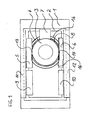
- die Trennbaugruppe schematisch in der Grundposition von unten gesehen,
- Fig. 2:
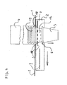
- einen Teil des Schiebeelementes schematisch von der Seite,
- Fig. 3:
- einen Teil des Schiebeelementes schematisch von der Seite, wobei das Schiebeelement in Pfeilrichtung horizontal verfahren ist im Verhältnis zur Darstellung in
Fig. 2 , - Fig. 4:
- einen Teil des Schiebeelementes schematisch von der Seite, nachdem das Schiebeelement in Pfeilrichtung horizontal nach links verfahren ist im Verhältnis zur Darstellung in
Fig. 3 , - Fig. 5:
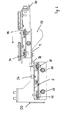
- eine alternative Trennbaugruppe aus einer Ansicht von unten,
- Fig. 6:
- die in
Fig. 5 gezeigte Trennbaugruppe in einer Seitenansicht in einer Ausgangsstellung, und - Fig. 7:
- die in
Fig. 5 gezeigte Trennbaugruppe in einer Trennstellung. - Die in
Fig. 1 gezeigten Becher 3 werden mit ihrer Öffnung nach oben zeigend in die Vorratsröhren und eine Ausgaberöhre 4 eingefüllt. Vorrats- und Ausgaberöhre oder Schacht bilden gemeinsam das Vorratsmagazin. - Dabei ist dem Vorratsmagazin ein Transportmechanismus zugeordnet, der den jeweiligen Becherstapel 15 dann, wenn die Ausgaberöhre 4 leer ist, den nächsten Becherstapel 15, der sich jeweils in einer der Vorratsröhren befindet, über die runde Ausgabeöffnung 16 transportiert. Damit wird die Vorratsröhre oder Vorratschacht zur Ausgaberöhre/Schacht 4. Die Vorratsröhren/Schächte sind in Reihe nebeneinander oder revolverartig als Trommel auf einer Grundplatte 1 angeordnet und sind Bestandteil des geschlossenen Magazins. Ist die Ausgaberöhre/Schacht 4 leer gefahren, so wird die nächste Vorratsröhre/Schacht über die Ausgabeposition 4 bewegt, wobei der Becherstapel 15 in den Ausgabeschacht 4 fällt und mit Hilfe von drei Tragblechen 5, 6 und 7 aufgefangen und in einer Fixposition gehalten wird. Die Tragbleche 5, 6 und 7 sind jeweils ein Auflageteil, gemeinsam bilden sie ein Tragelement. Mittels eines Sensors wird einer externen Steuerung gemeldet, dass sich nun genügend Becher in dem Ausgabeschacht 4 befinden und das System betriebsbereit ist.
- Die zwei Tragbleche 5 und 6 befinden sich gemäß
Fig. 1 waagerecht montiert und gegenüberliegend in einem rechteckigen rahmenartigen Schiebeelement 2, dieses wiederum ist in zwei Führungsschienen 11 und 12 gelagert und wird mittels eines elektrischen Antriebes aus der Ruheposition in eine vorgegebene Richtung, in dieser Beschreibung vorzugsweise nach rechts, von oben draufsehend, verfahren. Quer zu den Tragblechen 5 und 6 befindet sich das Tragblech 7. Alle drei Bleche oder Auflageteile - passend eingestellt - umgrenzen einen Radius, der identisch ist mit dem Radius des auszugebenden Bechers 3, gemessen unterhalb seiner Mundrolle 8. Die Tragebleche 5, 6 und 7 sind horizontal verstellbar, um auf den Durchmesser eines Bechers eingestellt werden zu können. Über den Tragwinkeln 5, 6 und 7 befindet sich, wenn sich das Schiebeelement 2 in der Grundposition befindet, der runde Ausschnitt 16 der Grundplatte 1 und bildet somit den Ausgabeschacht 4. - Gemäß
Fig. 1 und2 ruht der gesamte Becherstapel 15, der für die Ausgabe bestimmt ist, zunächst auf den Tragblechen 5, 6 und 7, wobei die Tragbleche 5, 6 im Ausführungsbeispiel als spezielle Tragwinkel ausgebildet sind, bei denen der nach unten zeigende Schenkel um 90° abgewinkelt ist. Haben die zur Ausgabe bestimmten Becher einen Durchmesser von zum Beispiel zwischen 60 und 90 mm, so haben die Tragbleche 5 und 6 eine Länge von ca. 80 mm. Der nach unten zeigende Winkel/Keil 13 und 14 hat eine Schenkellänge von 15 mm und ist abgeschrägt, um eine Keilwirkung zu bewirken. Die gewählten Maße können vom Ausführungsbeispiel abweichen. Die Schräge ist cirka 30 mm versetzt von der Vorderkante der Tragbleche 5 und 6 beginnend, und zwar in Richtung Tragblech 9 und 10 gesehen. Das Bechergebermodul befindet sich inFig.1 und2 in der Position: betriebsbereit. Dabei ruht der letzte, untere Becher 3 mittels seiner Mundrolle 8 und der darüber befindliche Rest des Becherstapels 15 senkrecht auf den Tragblechen 5, 6 und 7. - Erfolgt nun ein Ausgabeimpuls, so fährt der Antrieb das Schiebeelement 2 entsprechend
Fig. 3 nach rechts um beispielsweise 90 mm. Dabei bewegt sich das Tragblech 7 ausFig. 1 nach rechts und entfernt sich von dem zur Ausgabe bestimmten unteren Becher 3. Der Becher 3 wird jetzt nur noch an zwei Positionen über die Tragbleche 5 und 6 gehalten. Die Tragbleche 5 und 6 bewegen sich jetzt unter der Mundrolle 8 des Becher 3 her, dabei wird der gesamte Becherstapel 15 durch den ringförmigen Zylinder des Ausgaberöhre 4, dessen Unterkante sich ca. 1,5mm über den Tragblechen 5, 6 und 7 befindet, in Position gehalten. Dadurch, dass die Tragbleche 5 und 6 eine Länge von 80 mm haben und in Warteposition die Mundrolle 8 des unteren Bechers 3 mittig auf den Tragblechen 5 und 6 lagert, wird durch das Verfahren des Schiebeelementes 2 um 45 mm bewirkt, dass der gesamte Becherstapel 15 frei wird von den Tragblechen 5 und 6. - Jetzt werden die Tragbleche 9 und 10 aktiviert, die um den Abstand von einer Mundrolle zuzüglich einem halben Abstand von Mundrolle zu Mundrolle tiefer als die Tragbleche 5, 6 und 7 angebracht sind und unmittelbar dort beginnen, wo die Tragbleche 5 und 6 enden. Die Schiebebewegung hat bewirkt, dass jetzt der gesamte Becherstapel 15 um eine Stufe tiefer fällt, nämlich von den Tragblechen 5 und 6 auf die Tragbleche 9 und 10. Die Tragbleche 9 und 10 bilden jeweils wieder ein Auflageteil und beide gemeinsam ein Auflageelement. Der gesamte Becherstapel 15 ruht jetzt auf den Tragblechen 9 und 10. Das Fahren des Schiebeelementes 2 nach rechts ist jetzt beendet. Der Hub des Schiebeelementes entspricht dem Durchmesser des auszugebenden Bechers zuzüglich 10 bis 15 % Toleranz. Eine größere Toleranz ist ohne negativen Einfluss.
- Das Schiebeelement 2 wird danach über den Antrieb wieder nach links gem.
Fig. 4 verfahren. Dabei gleiten die Tragbleche 9 und 10 unter der Mundrolle 8 des unteren Bechers 3 her. Durch das kontinuierliche Verfahren nach links werden nun wiederum die Tragbleche 5 und 6, deren tragenden Oberfläche um den Mundrollenabstand zuzüglich Toleranz über den Tragblechen 9 und 10 angeordnet ist, zwischen die beiden Mundrollen des letzten unteren Bechers 3 und dem darüber befindlichen vorletzten Becher 17, die den Abstand von Mundrolle zu Mundrolle zu einander aufweisen, gefahren. Jetzt übernehmen die Tragbleche 5 und 6 eine tragende Funktion indem sie den vorletzten Becher 17 über seine Mundrolle von unten gesehen abstützen und damit gleichzeitig auch den Becherstapel 15. Der Becher 3, also der letzte untere Becher, wird nun von keinem Tragblech oder Tragwinkel mehr gehalten. Becher 3 ist jetzt senkrecht nach unten gerichtet frei. - Dadurch, dass die Becher sehr leicht sind, oder leicht aneinander haften, oder statisch aufgeladen sind, fallen sie schwerkraftbedingt nicht regelmäßig von alleine, deshalb wird eine Zwangstrennung ausgelöst, indem die Keile 13 und 14 der Tragbleche 5 und 6 zwischen die Mundrollen von Becher 3 und 17 geschoben werden, dadurch wird der Becher 3 nach unten gedrückt und dies bewirkt, dass immer eine Zwangstrennung eingeleitet wird. Die Keile 13 und 14 bilden im Ausführungsbeispiel die Abstreifelemente. Durch die schnelle Bewegung des Schiebeelementes 2 wird diese Kraft über die Keile 13 und 14 auf den Becher 3 übertragen. Dieser wird dabei beschleunigt und fällt zusätzlich schwerkraftbedingt sicher in die Ausgabestation.
- Dadurch, dass die Keile 13 und 14 eine Schenkellänge von 15 mm aufweisen, und wenn der Abstand von Mundrolle zu Mundrolle z.B. 3 mm beträgt, zuzüglich des halben Mundrollenabstands von z.B. 1,5 mm, so wird der Becher 3 in diesem Beispiel um 10,5 mm zwangsweise senkrecht nach unten bewegt. Durch diesen Vorgang ist es zu einer Zwangstrennung des unteren Bechers 3 von dem Stapel gekommen, der Becher wird zusätzlich durch die schnelle Bewegung der Keile beschleunigt und wird ergänzend mittels Schwerkraft in die Ausgabe gefördert. Danach kann ein neuer Zyklus gestartet werden.
- Die Vorrichtung ist so ausgelegt, dass die Tragbleche 5, 6, 7, 9 und 10 horizontal verstellbar sind, dadurch ist die Vorrichtung individuell auf den jeweiligen Durchmesser der auszugebenden Becher einstellbar. Die Tragbleche 5, 6 sowie 9, 10 befinden sich jeweils auf einer gemeinsamen tragenden Strebe. Diese beiden Streben sind hin zur Mitte des Bechergebers über jeweils zwei Stellschrauben stufenlos horizontal verstellbar. Damit ist ein leichtes Einstellen auf die unterschiedlichen Becherdurchmesser gewährleistet.
- Die Tragbleche 9 und 10 sind zusätzlich in der Höhe verstellbar entsprechend dem halben Abstand der Becher 15 von Mundrolle zu Mundrolle zuzüglich dem Stärkemaß der Mundrolle. Damit ist gewährleistet, dass die keilförmigen Segmente 13 und 14 der Tragwinkel 5 und 6 zwischen die Mundrollen der Becher 3 und 17 fahren können. Die Tragbleche 9 und 10 sind zu den Tragblechen 5 und 6 tiefer montiert entsprechend dem Abstand der Mundrollen, damit beim Zurückfahren des Schiebeelements 2 die Tragbleche 5 und 6 zwischen Becher 3 und 17 fahren können und der Trennungsprozess dadurch vollendet wird.
- In
Fig. 5 ist eine alternative Trennbaugruppe aus einer Ansicht von unten gezeigt. Abweichend vom vorstehend beschriebenen Ausführungsbeispiel sind hier die Auflageelemente 5,6 und 9,10 nicht in einem gemeinsamen Schlitten angeordnet, sondern getrennt voneinander. Der letzte Becher 3 eines nicht näher dargestellten darüber befindlichen Becherstapels 15 wird in der Ausgangsstellung von den Auflageteilen 5, 6, die gemeinsam ein erstes Auflageelement bilden, an der Mundrolle 8 gehalten. Die Auflageteile 5, 6 sind in einem ortsfest in der Vereinzelungsvorrichtung montierten Rahmen 50 gehalten. Die Auflageteile 5, 6 sind über Federn 52 in Querrichtung zur Hochachse des Becherstapels 15 und zum Rahmen 50 federnd gelagert. - In
Fig. 5 ist erkennbar, dass sich die Auflageteile 9, 10 in einem Schlitten 70 befinden, der quer zur Hochachse des Becherstapels 15 verlagerbar ist. Der Schlitten 70 kann nach links auf den Becher 3 zu verfahren werden.Fig. 6 zeigt die inFig. 5 gezeigte Trennbaugruppe in einer Seitenansicht in ihrer Ausgangsstellung. Von ihrer Ausgangsstellung aus wird der Schlitten 70 in Pfeilrichtung nach links verlagert. Am Rahmen 70 befinden sich auf gegenüberliegenden Seiten zwei Kulissen 72, die bei einer Verfahrbewegung des Schlittens 70 auf den Becher 3 zu auf die Anlaufrollen 54 treffen und diese im weiteren Ablauf der Verfahrbewegung zusammen mit den Auflageteilen 5, 6 nach außen auf die seitlichen Schenkel des Rahmens 50 zu drücken.Fig. 7 zeigt die inFig. 5 gezeigte Trennbaugruppe in einer Trennstellung. - In der Trennstellung vergrößert sich der Radius der Auflageteile 5, 6, und der Becher 3 kann mit der Mundrolle 8 zwischen diesen durch nach unten fallen. Da bei der Verschiebebewegung des Schlittens 70 die Auflageteile 9, 10 ebenfalls mit auf den letzten Becher 3 und den darüber befindlichen, zeichnerisch nicht dargestellten vorletzten Becher 17 zu verlagert worden sind, fällt der Becher 3 und der von ihm getragene Becherstapel 15 aus den Auflageteilen 5, 6 heraus.
- Da sich die Auflageteile 9, 10 in einer anderen Ebene oberhalb der Auflageteile 5, 6 befinden, haben sich die Auflageteile 9, 10 bei der Verschiebebewegung in den Zwischenraum zwischen der Mundrolle 8 des letzten Bechers 3 und der Mundrolle 8 des vorletzten Bechers 17 geschoben. Nachdem der letzte Becher 3 seinen Halt durch die Auflageteile 5, 6 verloren hat, stützt sich nun der vorletzte Becher 17 auf die nun sich darunter befindlichen Auflageteile 9, 10, die ein zweites Auflageelement bilden, ab.
- Bei einer weiter fortgesetzten Schiebebewegung gelangen die keilförmig gestalteten Abstreifelemente 13 und 14 an die Mundrolle des Bechers 3 und streift diesen nach unten ab.
- In der Seitenansicht in
Fig. 6 und7 sind die Gleitschienen 56, 74 erkennbar, an denen die Auflageteile 5, 6 und 9, 10 in einer Richtung quer zur Hochachse des Becherstapels 15 über Klemmschrauben an unterschiedliche Bechergrößen anpassbar sind. Eine Höhenverstellung kann über die Langlöcher 58 erfolgen. - Es wird darauf hingewiesen, dass die Erfindung nicht auf die vorstehenden gegenständlichen Beschreibungen als Ausführungsbeispiele beschränkt ist. Dem Fachmann bereitet es keine Schwierigkeiten, die Ausführungsbeispiele auf eine ihm als geeignet erscheinende Weise abzuwandeln und an die Erfordernisse eines konkreten Anwendungsfalls anzupassen, ohne dabei die Lehre der Erfindung zu verlassen.
Claims (10)
- Vereinzelungsvorrichtung zum Ausgeben eines Getränkebechers (3) aus einem in einem Vorratsmagazin gehaltenen Becherstapel (15), dadurch gekennzeichnet, dass die Vereinzelungsvorrichtung zumindest zwei räumlich in unterschiedlichen Ebenen zueinander angeordnete Auflageelemente, die auf unterschiedliche Becherformate einstellbar sind und auf denen der Becherstapel (15) wechselweise abgestützt ist, und ein beweglich angetriebenes Abstreifelement aufweist, das bei einer Abstreifbewegung in den Zwischenraum zwischen dem letzten und dem zweitletzten Becher des Becherstapels (15) beweglich ist und dabei den letzten Becher (3) vom vorletzten Becher (17) abstreift.
- Vereinzelungsvorrichtung nach Anspruch 1, dadurch gekennzeichnet, dass das Abstreifelement quer zur Hochachse des Becherstapels (15) beweglich ist.
- Vereinzelungsvorrichtung nach Anspruch 1 oder 2, dadurch gekennzeichnet, dass das Abstreifelement gemeinsam mit einem Auflageelement beweglich ist.
- Vereinzelungsvorrichtung nach Anspruch 3, dadurch gekennzeichnet, dass mit dem Abstreifelement und dem Auflageelement zusätzlich ein Druckelement zur Verstellung eines Auflageelements beweglich ist.
- Vereinzelungsvorrichtung nach einem der vorhergehenden Ansprüche, dadurch gekennzeichnet, dass das Abstreifelement und ein Auflageelement auf einem gemeinsamen Schlitten angeordnet sind.
- Vereinzelungsvorrichtung nach Anspruch 5, dadurch gekennzeichnet, dass auf dem gemeinsamen Schlitten ein zweites Auflageelement angeordnet ist.
- Vereinzelungsvorrichtung nach einem der Ansprüche 1 bis 6, dadurch gekennzeichnet, dass die Auflageelemente in ihrer Einbaulage höhenverstellbar und/oder quer zur Hochachse des Becherstapels (15) verstellbar sind.
- Vereinzelungsvorrichtung nach einem der Ansprüche 1 bis 7, dadurch gekennzeichnet, dass das Abstreifelement und die Auflageelemente auf unterschiedliche Abstände der Becher (3, 17) bzw. deren Mundrollen (8) und/oder auf unterschiedliche Durchmesser der Becher (3, 17) einstellbar sind.
- Vereinzelungsvorrichtung nach einem der Ansprüche 1 bis 8, dadurch gekennzeichnet, dass die Becher (3) in der Entnahmeposition mittels der jeweiligen Mundrolle (8) an den Auflageelementen gehalten sind.
- Vereinzelungsvorrichtung nach einem der Ansprüche 1 bis 9, dadurch gekennzeichnet, dass die Haltezeiten des ersten und zweiten Auflageelements, in denen diese den letzten und/oder oder den vorletzten Becher (3, 17) halten, bei einer Verstellung genau aneinander angrenzen oder sich überschneiden.
Priority Applications (2)
| Application Number | Priority Date | Filing Date | Title |
|---|---|---|---|
| EP16000352.1A EP3050468A1 (de) | 2010-12-03 | 2011-11-25 | Vereinzelungsvorrichtung zum ausgeben eines getränkebechers |
| PL11190713T PL2460442T3 (pl) | 2010-12-03 | 2011-11-25 | Urządzenie do rozdzielania, przeznaczone do dystrybucji kubka na napoje |
Applications Claiming Priority (2)
| Application Number | Priority Date | Filing Date | Title |
|---|---|---|---|
| DE202010016346U DE202010016346U1 (de) | 2010-12-03 | 2010-12-03 | Einstellbare Vorrichtung zum automatischen Vereinzeln und Ausgeben von konischen Getränkebechern unterschiedlicher Größen |
| DE102011016492.8A DE102011016492B4 (de) | 2010-12-03 | 2011-04-08 | Vereinzelungsvorrichtung zum Ausgeben eines Getränkebechers |
Related Child Applications (2)
| Application Number | Title | Priority Date | Filing Date |
|---|---|---|---|
| EP16000352.1A Division EP3050468A1 (de) | 2010-12-03 | 2011-11-25 | Vereinzelungsvorrichtung zum ausgeben eines getränkebechers |
| EP16000352.1A Division-Into EP3050468A1 (de) | 2010-12-03 | 2011-11-25 | Vereinzelungsvorrichtung zum ausgeben eines getränkebechers |
Publications (2)
| Publication Number | Publication Date |
|---|---|
| EP2460442A1 true EP2460442A1 (de) | 2012-06-06 |
| EP2460442B1 EP2460442B1 (de) | 2016-12-28 |
Family
ID=45002821
Family Applications (2)
| Application Number | Title | Priority Date | Filing Date |
|---|---|---|---|
| EP11190713.5A Revoked EP2460442B1 (de) | 2010-12-03 | 2011-11-25 | Vereinzelungsvorrichtung zum Ausgeben eines Getränkebechers |
| EP16000352.1A Withdrawn EP3050468A1 (de) | 2010-12-03 | 2011-11-25 | Vereinzelungsvorrichtung zum ausgeben eines getränkebechers |
Family Applications After (1)
| Application Number | Title | Priority Date | Filing Date |
|---|---|---|---|
| EP16000352.1A Withdrawn EP3050468A1 (de) | 2010-12-03 | 2011-11-25 | Vereinzelungsvorrichtung zum ausgeben eines getränkebechers |
Country Status (5)
| Country | Link |
|---|---|
| EP (2) | EP2460442B1 (de) |
| CN (1) | CN202775890U (de) |
| DE (1) | DE102011016492B4 (de) |
| ES (1) | ES2621108T3 (de) |
| PL (1) | PL2460442T3 (de) |
Cited By (3)
| Publication number | Priority date | Publication date | Assignee | Title |
|---|---|---|---|---|
| WO2021244965A1 (de) | 2020-06-04 | 2021-12-09 | Wmf Gmbh | Vorrichtung zur vereinzelung von bechern eines becherstapels und verwendungen hiervon |
| CN114348672A (zh) * | 2021-12-15 | 2022-04-15 | 浙江佰润科技有限公司 | 一种自动分杯装置和自动分杯方法 |
| US12116199B2 (en) | 2021-12-16 | 2024-10-15 | Cfs Brands, Llc | Dispenser assembly for disposable lids |
Families Citing this family (6)
| Publication number | Priority date | Publication date | Assignee | Title |
|---|---|---|---|---|
| DE102011016492B4 (de) | 2010-12-03 | 2021-03-18 | Klaus Rudolph | Vereinzelungsvorrichtung zum Ausgeben eines Getränkebechers |
| CN102756813B (zh) * | 2012-07-03 | 2014-01-29 | 杭州中亚机械股份有限公司 | 食品灌装自动落杯装置 |
| DE202013005642U1 (de) * | 2013-06-24 | 2013-07-25 | Frenzel Gmbh | Verkaufsautomat |
| CN113080656B (zh) * | 2021-03-16 | 2022-05-31 | 四川阿泰因机器人智能装备有限公司 | 一种自动提供纸杯的落杯组件及其装置 |
| CN113966942A (zh) * | 2021-11-23 | 2022-01-25 | 富岭科技股份有限公司 | 一种刀、叉、勺餐具组的投放装置 |
| CN221661085U (zh) * | 2023-12-20 | 2024-09-06 | 湖南宏工智能科技有限公司 | 容器分离放置机构及包装机 |
Citations (4)
| Publication number | Priority date | Publication date | Assignee | Title |
|---|---|---|---|---|
| US2730268A (en) * | 1952-04-22 | 1956-01-10 | Marbac Corp | Cup dispenser |
| DE2318721A1 (de) * | 1973-04-13 | 1974-10-24 | Erich Schmitz | Auswerfervorrichtung fuer konische becher |
| US6550638B1 (en) * | 1999-11-26 | 2003-04-22 | Fuji Electric Co., Ltd. | Cup-supplying apparatus |
| WO2006118783A1 (en) * | 2005-05-04 | 2006-11-09 | Walsh Nicholas R | Beverage lid dispenser |
Family Cites Families (13)
| Publication number | Priority date | Publication date | Assignee | Title |
|---|---|---|---|---|
| US1027353A (en) * | 1911-04-04 | 1912-05-21 | Dosier H Mosteller | Commodity-receptacle. |
| US2373217A (en) * | 1943-03-06 | 1945-04-10 | Allen Alexander | Office cabinet |
| US2606087A (en) * | 1950-04-19 | 1952-08-05 | White Castle System | Receptacle for storing and dispensing nested drinking cups |
| US2780388A (en) * | 1954-05-04 | 1957-02-05 | Continental Can Co | Adjustable cup dispenser |
| FR2537307A1 (fr) * | 1982-07-02 | 1984-06-08 | Polyvend | Module separateur de gobelets et distributeur automatique equipe de ce module |
| GB2212793B (en) * | 1987-12-01 | 1991-07-10 | Cantina Limited | Separation apparatus |
| FR2625888A1 (fr) * | 1988-01-20 | 1989-07-21 | App Automatiques Ste Indle | Dispositif de distribution de gobelets empiles |
| JPH0647857Y2 (ja) | 1988-06-10 | 1994-12-07 | ホシザキ電機株式会社 | カップ放出装置 |
| ES2025445A6 (es) * | 1990-07-19 | 1992-03-16 | Azkoyen Ind Sa | Dispositivo suministrador de vasos para maquinas expendedoras de bebidas. |
| US5827068A (en) * | 1996-12-31 | 1998-10-27 | Michelson Packaging Co. | Fruit packaging tray usable with a denesting apparatus |
| US20040065672A1 (en) * | 2002-10-04 | 2004-04-08 | California Quality Plastics, Inc. | Cup dispenser |
| DE102011016492B4 (de) | 2010-12-03 | 2021-03-18 | Klaus Rudolph | Vereinzelungsvorrichtung zum Ausgeben eines Getränkebechers |
| DE202010016346U1 (de) | 2010-12-03 | 2011-04-07 | Rudolph, Klaus | Einstellbare Vorrichtung zum automatischen Vereinzeln und Ausgeben von konischen Getränkebechern unterschiedlicher Größen |
-
2011
- 2011-04-08 DE DE102011016492.8A patent/DE102011016492B4/de active Active
- 2011-11-25 PL PL11190713T patent/PL2460442T3/pl unknown
- 2011-11-25 ES ES11190713.5T patent/ES2621108T3/es active Active
- 2011-11-25 EP EP11190713.5A patent/EP2460442B1/de not_active Revoked
- 2011-11-25 EP EP16000352.1A patent/EP3050468A1/de not_active Withdrawn
- 2011-12-05 CN CN2011205077618U patent/CN202775890U/zh not_active Expired - Fee Related
Patent Citations (4)
| Publication number | Priority date | Publication date | Assignee | Title |
|---|---|---|---|---|
| US2730268A (en) * | 1952-04-22 | 1956-01-10 | Marbac Corp | Cup dispenser |
| DE2318721A1 (de) * | 1973-04-13 | 1974-10-24 | Erich Schmitz | Auswerfervorrichtung fuer konische becher |
| US6550638B1 (en) * | 1999-11-26 | 2003-04-22 | Fuji Electric Co., Ltd. | Cup-supplying apparatus |
| WO2006118783A1 (en) * | 2005-05-04 | 2006-11-09 | Walsh Nicholas R | Beverage lid dispenser |
Cited By (5)
| Publication number | Priority date | Publication date | Assignee | Title |
|---|---|---|---|---|
| WO2021244965A1 (de) | 2020-06-04 | 2021-12-09 | Wmf Gmbh | Vorrichtung zur vereinzelung von bechern eines becherstapels und verwendungen hiervon |
| DE102020207032A1 (de) | 2020-06-04 | 2021-12-09 | Wmf Gmbh | Vorrichtung zur Vereinzelung von Bechern eines Becherstapels und Verwendungen hiervon |
| CN114348672A (zh) * | 2021-12-15 | 2022-04-15 | 浙江佰润科技有限公司 | 一种自动分杯装置和自动分杯方法 |
| CN114348672B (zh) * | 2021-12-15 | 2023-12-15 | 浙江佰润科技有限公司 | 一种自动分杯装置和自动分杯方法 |
| US12116199B2 (en) | 2021-12-16 | 2024-10-15 | Cfs Brands, Llc | Dispenser assembly for disposable lids |
Also Published As
| Publication number | Publication date |
|---|---|
| DE102011016492A1 (de) | 2012-06-06 |
| ES2621108T3 (es) | 2017-07-03 |
| EP3050468A1 (de) | 2016-08-03 |
| PL2460442T3 (pl) | 2017-07-31 |
| CN202775890U (zh) | 2013-03-13 |
| EP2460442B1 (de) | 2016-12-28 |
| DE102011016492B4 (de) | 2021-03-18 |
Similar Documents
| Publication | Publication Date | Title |
|---|---|---|
| EP2460442B1 (de) | Vereinzelungsvorrichtung zum Ausgeben eines Getränkebechers | |
| DE2943769A1 (de) | Vorrichtung und steuerung zur entnahme einzelner rohre aus einem vorratsbehaelter | |
| EP2797814B1 (de) | Applikatorvorrichtung für wickeletiketten | |
| CH457268A (de) | Vorrichtung zum Ablegen flächenhafter Gegenstände zu einem Stapel | |
| DE1917062C3 (de) | Vorrichtung zum selbsttätigen Verteilen von Gegenständen | |
| DE69405351T2 (de) | Maschine zum Verpacken von Gegenständen | |
| DE3217385A1 (de) | Verfahren zum entnehmen von wenigstens einem flachen gegenstand aus einem stapel und anwendung des verfahrens | |
| DE102013014631A1 (de) | Tabletttransportvorrichtung und Verfahren zur kontinuierlichen Förderung mehrerer Tabletts unter Einsatz einer Tabletttransportvorrichtung | |
| DE102013011027A1 (de) | Vorrichtung für die Zuführung von Stückgutbehältern und Transportwagen hierfür | |
| DE102009000750A1 (de) | Druckformzuführung und ein Verfahren zum Transport zumindest einer Druckform | |
| WO2017129720A1 (de) | Formenein- und ausstapler | |
| DE1586068A1 (de) | Apparat zum Transportieren und UEberleiten von Gegenstaenden in periodischen Arbeitsgaengen ohne Leerzeit von Abgabemaschinen auf Aufnahmemaschinen,insbesondere fuer Verpackungsautomaten u.dgl. | |
| DE202010016346U1 (de) | Einstellbare Vorrichtung zum automatischen Vereinzeln und Ausgeben von konischen Getränkebechern unterschiedlicher Größen | |
| DE8900619U1 (de) | Vorrichtung zur Ausgabe von in Stapeln angeordneten Bechern | |
| EP1873096B1 (de) | Vorrichtung zum Nachfüllen von Stapeln flacher, auf der Kante stehenden Gegenständen in einer Vereinzelungseinrichtung | |
| DE2628256B2 (de) | Vorrichtung zum Stapeln von ringförmigen Gegenständen, insbesondere von Wälzlagerringen | |
| EP2689664A2 (de) | Verfahren und Anlage zur zeitlich begrenzten Aufnahme von Backgutträgern | |
| DE102024121673A1 (de) | Vorrichtung zum Verarbeiten pharmazeutischer Behälter | |
| DE1939536B2 (de) | Vorrichtung zum Zuführen von mit Zigaretten gefüllten Behältern zu einer die Behälter entleerenden Kippeinrichtung | |
| DE20304880U1 (de) | Zwischenspeicher | |
| DE3300530A1 (de) | Geraet und verfahren zur lieferung von gegenstaenden | |
| DE2050083A1 (de) | Vakuumbetatigte Blattfördereinnchtung fur Zeitungsanzeigeneingabe | |
| DE1940227A1 (de) | Transportvorrichtung | |
| EP1652799A1 (de) | Vorrichtung zum Vereinzeln von Stückgütern | |
| DE1118688B (de) | Vorrichtung zum paketweisen Gruppieren und Banderolieren einer bestimmten Stueckzahl von Briefumschlaegen |
Legal Events
| Date | Code | Title | Description |
|---|---|---|---|
| PUAI | Public reference made under article 153(3) epc to a published international application that has entered the european phase |
Free format text: ORIGINAL CODE: 0009012 |
|
| AK | Designated contracting states |
Kind code of ref document: A1 Designated state(s): AL AT BE BG CH CY CZ DE DK EE ES FI FR GB GR HR HU IE IS IT LI LT LU LV MC MK MT NL NO PL PT RO RS SE SI SK SM TR |
|
| AX | Request for extension of the european patent |
Extension state: BA ME |
|
| 17P | Request for examination filed |
Effective date: 20121121 |
|
| 17Q | First examination report despatched |
Effective date: 20140214 |
|
| APBK | Appeal reference recorded |
Free format text: ORIGINAL CODE: EPIDOSNREFNE |
|
| APBN | Date of receipt of notice of appeal recorded |
Free format text: ORIGINAL CODE: EPIDOSNNOA2E |
|
| APBR | Date of receipt of statement of grounds of appeal recorded |
Free format text: ORIGINAL CODE: EPIDOSNNOA3E |
|
| APBV | Interlocutory revision of appeal recorded |
Free format text: ORIGINAL CODE: EPIDOSNIRAPE |
|
| GRAP | Despatch of communication of intention to grant a patent |
Free format text: ORIGINAL CODE: EPIDOSNIGR1 |
|
| GRAS | Grant fee paid |
Free format text: ORIGINAL CODE: EPIDOSNIGR3 |
|
| INTG | Intention to grant announced |
Effective date: 20160930 |
|
| GRAA | (expected) grant |
Free format text: ORIGINAL CODE: 0009210 |
|
| STAA | Information on the status of an ep patent application or granted ep patent |
Free format text: STATUS: THE PATENT HAS BEEN GRANTED |
|
| AK | Designated contracting states |
Kind code of ref document: B1 Designated state(s): AL AT BE BG CH CY CZ DE DK EE ES FI FR GB GR HR HU IE IS IT LI LT LU LV MC MK MT NL NO PL PT RO RS SE SI SK SM TR |
|
| REG | Reference to a national code |
Ref country code: GB Ref legal event code: FG4D Free format text: NOT ENGLISH |
|
| REG | Reference to a national code |
Ref country code: CH Ref legal event code: EP |
|
| REG | Reference to a national code |
Ref country code: AT Ref legal event code: REF Ref document number: 856569 Country of ref document: AT Kind code of ref document: T Effective date: 20170115 |
|
| REG | Reference to a national code |
Ref country code: IE Ref legal event code: FG4D Free format text: LANGUAGE OF EP DOCUMENT: GERMAN |
|
| REG | Reference to a national code |
Ref country code: DE Ref legal event code: R096 Ref document number: 502011011408 Country of ref document: DE |
|
| PG25 | Lapsed in a contracting state [announced via postgrant information from national office to epo] |
Ref country code: LV Free format text: LAPSE BECAUSE OF FAILURE TO SUBMIT A TRANSLATION OF THE DESCRIPTION OR TO PAY THE FEE WITHIN THE PRESCRIBED TIME-LIMIT Effective date: 20161228 |
|
| REG | Reference to a national code |
Ref country code: LT Ref legal event code: MG4D |
|
| PG25 | Lapsed in a contracting state [announced via postgrant information from national office to epo] |
Ref country code: GR Free format text: LAPSE BECAUSE OF FAILURE TO SUBMIT A TRANSLATION OF THE DESCRIPTION OR TO PAY THE FEE WITHIN THE PRESCRIBED TIME-LIMIT Effective date: 20170329 Ref country code: LT Free format text: LAPSE BECAUSE OF FAILURE TO SUBMIT A TRANSLATION OF THE DESCRIPTION OR TO PAY THE FEE WITHIN THE PRESCRIBED TIME-LIMIT Effective date: 20161228 Ref country code: SE Free format text: LAPSE BECAUSE OF FAILURE TO SUBMIT A TRANSLATION OF THE DESCRIPTION OR TO PAY THE FEE WITHIN THE PRESCRIBED TIME-LIMIT Effective date: 20161228 Ref country code: NO Free format text: LAPSE BECAUSE OF FAILURE TO SUBMIT A TRANSLATION OF THE DESCRIPTION OR TO PAY THE FEE WITHIN THE PRESCRIBED TIME-LIMIT Effective date: 20170328 |
|
| PG25 | Lapsed in a contracting state [announced via postgrant information from national office to epo] |
Ref country code: HR Free format text: LAPSE BECAUSE OF FAILURE TO SUBMIT A TRANSLATION OF THE DESCRIPTION OR TO PAY THE FEE WITHIN THE PRESCRIBED TIME-LIMIT Effective date: 20161228 Ref country code: FI Free format text: LAPSE BECAUSE OF FAILURE TO SUBMIT A TRANSLATION OF THE DESCRIPTION OR TO PAY THE FEE WITHIN THE PRESCRIBED TIME-LIMIT Effective date: 20161228 Ref country code: RS Free format text: LAPSE BECAUSE OF FAILURE TO SUBMIT A TRANSLATION OF THE DESCRIPTION OR TO PAY THE FEE WITHIN THE PRESCRIBED TIME-LIMIT Effective date: 20161228 |
|
| REG | Reference to a national code |
Ref country code: ES Ref legal event code: FG2A Ref document number: 2621108 Country of ref document: ES Kind code of ref document: T3 Effective date: 20170703 |
|
| PG25 | Lapsed in a contracting state [announced via postgrant information from national office to epo] |
Ref country code: SK Free format text: LAPSE BECAUSE OF FAILURE TO SUBMIT A TRANSLATION OF THE DESCRIPTION OR TO PAY THE FEE WITHIN THE PRESCRIBED TIME-LIMIT Effective date: 20161228 Ref country code: RO Free format text: LAPSE BECAUSE OF FAILURE TO SUBMIT A TRANSLATION OF THE DESCRIPTION OR TO PAY THE FEE WITHIN THE PRESCRIBED TIME-LIMIT Effective date: 20161228 Ref country code: EE Free format text: LAPSE BECAUSE OF FAILURE TO SUBMIT A TRANSLATION OF THE DESCRIPTION OR TO PAY THE FEE WITHIN THE PRESCRIBED TIME-LIMIT Effective date: 20161228 Ref country code: IS Free format text: LAPSE BECAUSE OF FAILURE TO SUBMIT A TRANSLATION OF THE DESCRIPTION OR TO PAY THE FEE WITHIN THE PRESCRIBED TIME-LIMIT Effective date: 20170428 Ref country code: CZ Free format text: LAPSE BECAUSE OF FAILURE TO SUBMIT A TRANSLATION OF THE DESCRIPTION OR TO PAY THE FEE WITHIN THE PRESCRIBED TIME-LIMIT Effective date: 20161228 |
|
| REG | Reference to a national code |
Ref country code: NL Ref legal event code: FP |
|
| PG25 | Lapsed in a contracting state [announced via postgrant information from national office to epo] |
Ref country code: PT Free format text: LAPSE BECAUSE OF FAILURE TO SUBMIT A TRANSLATION OF THE DESCRIPTION OR TO PAY THE FEE WITHIN THE PRESCRIBED TIME-LIMIT Effective date: 20170428 Ref country code: BG Free format text: LAPSE BECAUSE OF FAILURE TO SUBMIT A TRANSLATION OF THE DESCRIPTION OR TO PAY THE FEE WITHIN THE PRESCRIBED TIME-LIMIT Effective date: 20170328 Ref country code: SM Free format text: LAPSE BECAUSE OF FAILURE TO SUBMIT A TRANSLATION OF THE DESCRIPTION OR TO PAY THE FEE WITHIN THE PRESCRIBED TIME-LIMIT Effective date: 20161228 Ref country code: IT Free format text: LAPSE BECAUSE OF FAILURE TO SUBMIT A TRANSLATION OF THE DESCRIPTION OR TO PAY THE FEE WITHIN THE PRESCRIBED TIME-LIMIT Effective date: 20161228 |
|
| REG | Reference to a national code |
Ref country code: DE Ref legal event code: R026 Ref document number: 502011011408 Country of ref document: DE |
|
| PLBI | Opposition filed |
Free format text: ORIGINAL CODE: 0009260 |
|
| PLAX | Notice of opposition and request to file observation + time limit sent |
Free format text: ORIGINAL CODE: EPIDOSNOBS2 |
|
| 26 | Opposition filed |
Opponent name: SIELAFF GMBH & CO. KG AUTOMATENBAU Effective date: 20170928 |
|
| REG | Reference to a national code |
Ref country code: FR Ref legal event code: PLFP Year of fee payment: 7 |
|
| PG25 | Lapsed in a contracting state [announced via postgrant information from national office to epo] |
Ref country code: DK Free format text: LAPSE BECAUSE OF FAILURE TO SUBMIT A TRANSLATION OF THE DESCRIPTION OR TO PAY THE FEE WITHIN THE PRESCRIBED TIME-LIMIT Effective date: 20161228 |
|
| PGFP | Annual fee paid to national office [announced via postgrant information from national office to epo] |
Ref country code: FR Payment date: 20171124 Year of fee payment: 7 |
|
| PG25 | Lapsed in a contracting state [announced via postgrant information from national office to epo] |
Ref country code: SI Free format text: LAPSE BECAUSE OF FAILURE TO SUBMIT A TRANSLATION OF THE DESCRIPTION OR TO PAY THE FEE WITHIN THE PRESCRIBED TIME-LIMIT Effective date: 20161228 |
|
| PGFP | Annual fee paid to national office [announced via postgrant information from national office to epo] |
Ref country code: BE Payment date: 20171124 Year of fee payment: 7 |
|
| PLBB | Reply of patent proprietor to notice(s) of opposition received |
Free format text: ORIGINAL CODE: EPIDOSNOBS3 |
|
| PG25 | Lapsed in a contracting state [announced via postgrant information from national office to epo] |
Ref country code: MC Free format text: LAPSE BECAUSE OF FAILURE TO SUBMIT A TRANSLATION OF THE DESCRIPTION OR TO PAY THE FEE WITHIN THE PRESCRIBED TIME-LIMIT Effective date: 20161228 |
|
| REG | Reference to a national code |
Ref country code: IE Ref legal event code: MM4A |
|
| PG25 | Lapsed in a contracting state [announced via postgrant information from national office to epo] |
Ref country code: MT Free format text: LAPSE BECAUSE OF FAILURE TO SUBMIT A TRANSLATION OF THE DESCRIPTION OR TO PAY THE FEE WITHIN THE PRESCRIBED TIME-LIMIT Effective date: 20161228 |
|
| PG25 | Lapsed in a contracting state [announced via postgrant information from national office to epo] |
Ref country code: IE Free format text: LAPSE BECAUSE OF NON-PAYMENT OF DUE FEES Effective date: 20171125 |
|
| PGFP | Annual fee paid to national office [announced via postgrant information from national office to epo] |
Ref country code: LU Payment date: 20181129 Year of fee payment: 8 |
|
| PGFP | Annual fee paid to national office [announced via postgrant information from national office to epo] |
Ref country code: NL Payment date: 20181129 Year of fee payment: 8 Ref country code: PL Payment date: 20181029 Year of fee payment: 8 Ref country code: DE Payment date: 20181129 Year of fee payment: 8 Ref country code: AT Payment date: 20181129 Year of fee payment: 8 |
|
| PGFP | Annual fee paid to national office [announced via postgrant information from national office to epo] |
Ref country code: CH Payment date: 20181130 Year of fee payment: 8 Ref country code: ES Payment date: 20181203 Year of fee payment: 8 Ref country code: GB Payment date: 20181130 Year of fee payment: 8 |
|
| PLAB | Opposition data, opponent's data or that of the opponent's representative modified |
Free format text: ORIGINAL CODE: 0009299OPPO |
|
| R26 | Opposition filed (corrected) |
Opponent name: SIELAFF GMBH & CO. KG AUTOMATENBAU Effective date: 20170928 |
|
| PG25 | Lapsed in a contracting state [announced via postgrant information from national office to epo] |
Ref country code: HU Free format text: LAPSE BECAUSE OF FAILURE TO SUBMIT A TRANSLATION OF THE DESCRIPTION OR TO PAY THE FEE WITHIN THE PRESCRIBED TIME-LIMIT; INVALID AB INITIO Effective date: 20111125 |
|
| RDAF | Communication despatched that patent is revoked |
Free format text: ORIGINAL CODE: EPIDOSNREV1 |
|
| REG | Reference to a national code |
Ref country code: BE Ref legal event code: MM Effective date: 20181130 |
|
| APAH | Appeal reference modified |
Free format text: ORIGINAL CODE: EPIDOSCREFNO |
|
| APBM | Appeal reference recorded |
Free format text: ORIGINAL CODE: EPIDOSNREFNO |
|
| APBP | Date of receipt of notice of appeal recorded |
Free format text: ORIGINAL CODE: EPIDOSNNOA2O |
|
| PG25 | Lapsed in a contracting state [announced via postgrant information from national office to epo] |
Ref country code: CY Free format text: LAPSE BECAUSE OF NON-PAYMENT OF DUE FEES Effective date: 20161228 Ref country code: FR Free format text: LAPSE BECAUSE OF NON-PAYMENT OF DUE FEES Effective date: 20181130 |
|
| REG | Reference to a national code |
Ref country code: DE Ref legal event code: R064 Ref document number: 502011011408 Country of ref document: DE Ref country code: DE Ref legal event code: R103 Ref document number: 502011011408 Country of ref document: DE |
|
| PG25 | Lapsed in a contracting state [announced via postgrant information from national office to epo] |
Ref country code: MK Free format text: LAPSE BECAUSE OF FAILURE TO SUBMIT A TRANSLATION OF THE DESCRIPTION OR TO PAY THE FEE WITHIN THE PRESCRIBED TIME-LIMIT Effective date: 20161228 Ref country code: BE Free format text: LAPSE BECAUSE OF NON-PAYMENT OF DUE FEES Effective date: 20181130 |
|
| APAH | Appeal reference modified |
Free format text: ORIGINAL CODE: EPIDOSCREFNO |
|
| APAH | Appeal reference modified |
Free format text: ORIGINAL CODE: EPIDOSCREFNO |
|
| APBU | Appeal procedure closed |
Free format text: ORIGINAL CODE: EPIDOSNNOA9O |
|
| RDAG | Patent revoked |
Free format text: ORIGINAL CODE: 0009271 |
|
| STAA | Information on the status of an ep patent application or granted ep patent |
Free format text: STATUS: PATENT REVOKED |
|
| REG | Reference to a national code |
Ref country code: CH Ref legal event code: PL |
|
| REG | Reference to a national code |
Ref country code: FI Ref legal event code: MGE |
|
| 27W | Patent revoked |
Effective date: 20191119 |
|
| GBPR | Gb: patent revoked under art. 102 of the ep convention designating the uk as contracting state |
Effective date: 20191119 |
|
| PG25 | Lapsed in a contracting state [announced via postgrant information from national office to epo] |
Ref country code: AL Free format text: LAPSE BECAUSE OF FAILURE TO SUBMIT A TRANSLATION OF THE DESCRIPTION OR TO PAY THE FEE WITHIN THE PRESCRIBED TIME-LIMIT Effective date: 20161228 |
|
| REG | Reference to a national code |
Ref country code: AT Ref legal event code: MA03 Ref document number: 856569 Country of ref document: AT Kind code of ref document: T Effective date: 20191119 |
|
| PG25 | Lapsed in a contracting state [announced via postgrant information from national office to epo] |
Ref country code: TR Free format text: LAPSE BECAUSE OF FAILURE TO SUBMIT A TRANSLATION OF THE DESCRIPTION OR TO PAY THE FEE WITHIN THE PRESCRIBED TIME-LIMIT Effective date: 20161228 |