EP2460438B1 - Stühle für ein Panikverkettungssystem - Google Patents
Stühle für ein Panikverkettungssystem Download PDFInfo
- Publication number
- EP2460438B1 EP2460438B1 EP20110007975 EP11007975A EP2460438B1 EP 2460438 B1 EP2460438 B1 EP 2460438B1 EP 20110007975 EP20110007975 EP 20110007975 EP 11007975 A EP11007975 A EP 11007975A EP 2460438 B1 EP2460438 B1 EP 2460438B1
- Authority
- EP
- European Patent Office
- Prior art keywords
- chair
- front leg
- coupling
- connecting strut
- coupling half
- Prior art date
- Legal status (The legal status is an assumption and is not a legal conclusion. Google has not performed a legal analysis and makes no representation as to the accuracy of the status listed.)
- Active
Links
Images


Classifications
-
- A—HUMAN NECESSITIES
- A47—FURNITURE; DOMESTIC ARTICLES OR APPLIANCES; COFFEE MILLS; SPICE MILLS; SUCTION CLEANERS IN GENERAL
- A47C—CHAIRS; SOFAS; BEDS
- A47C1/00—Chairs adapted for special purposes
- A47C1/12—Theatre, auditorium or similar chairs
- A47C1/124—Separate chairs, connectible together into a row
Definitions
- the present invention relates to a chair for a panic linkage system.
- the invention has for its object to propose a chair for a panic linkage, in which the disadvantages known from the prior art avoided or at least greatly reduced.
- the object is achieved with a chair for a panic linkage system according to claim 1.
- the inventive design avoids loose chair connector completely and is due to their construction as easy as fast to assemble.
- the panic linking resulting parts of the chair according to the invention are in the chair itself integrated and unnecessary further special precautions, if the chair is to be linked with his peers.
- a particular finesse of the chair according to the invention is that it is a complete and designerisch appealing chair even without concatenation. The concatenation is done by a minimal effort for the slight lifting of a chair such that z. B. his right half of the coupling is introduced from behind and into the adjacent left half of the coupling of the neighboring chair and by lowering the chair to the ground, the chairs are fixed together or together.
- the chair only needs to be raised a few centimeters above the ground, depending on the profile chosen for the front legs, and, as it were, led over the neighboring chair and only be returned to the floor in the coupling from behind.
- the chair is characterized in that the rearwardly extending continuations of up to armrest height raised front legs from the chained state adjacent to each other to form an armrest.
- the chair is characterized in that the coupling halves are each arranged in a node resulting from a compound of the continuations with the associated hind leg. This advantageously results in a frame-like chair, which shows even greater stability.
- the chair is characterized in that the coupling halves are formed substantially in the shape of a yin-yang. This makes it possible to achieve a secure and shapely coupling of the adjacent chairs.
- the chair is characterized in that the profile of the front legs (21, 22) and / or the rear legs (41, 42) has a polygonal cross-section. This advantageously further decorative accents can be realized.
- the chair is characterized in that the chair is a cantilever.
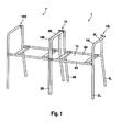
- Fig. 1 can be seen two chairs 1 and 1 ', which are shown here for the sake of clarity in all figures without seat. Both chairs are absolutely identical, so that all references to the left chair 1 as well as the right chair 1'gelten.
- the chair 1 stands on two front legs 21 and 22 connected by a connecting strut 6V and two rear legs 41 and 42 connected by means of a connecting strut 6H.
- the front legs 2R and 2L projecting upwardly above a seat plane 13 that is essentially defined by the connecting struts 6V and 6H are used in the present embodiment Embodiment over armrest arches 14R, 14L in continuations 9R and 9L on.
- the extensions 9R and 9L terminate in coupling halves 10R and 10L, which are partially more fully apparent in other figures, and, if extended as shown here from about the front legs to the rear legs of the chair, form double armrests 12R, 12L , now consisting of the continuations 9R and 9L.
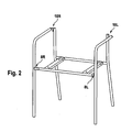
- a right-side recess 8R open to the rear and a recess 8L open towards the front can be seen in which, as in FIG Fig. 1 can be seen well, the respective front legs or their profile cross sections 3 of the respective neighboring chair fit and insert in assembling or concatenating.
- Fig. 2 also shows well the coupling half 10R and the complementary coupling half 10L.
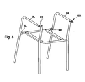
- Fig. 3 are the ones out Fig. 2 known objects from obliquely behind.
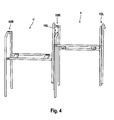
- Fig. 4 shows the right chair 1 slightly raised above the left chair 1 ', and this is, however, in Fig. 4 difficult to recognize (this is the later to be described Fig. 5 ), with its right continuation 9R and the attached coupling half 10R slightly behind the left continuation 9L and the attached thereto coupling half 10L of the chair 1 '.
- the situation shows the state just before lowering and from the rear inserting the right coupling half 10R of the left chair 1 into the left coupling half 10L of the right chair 1 '.
- FIG. 6 shows an exemplary embodiment of a coupling halves pair 10R, 10L, for the sake of clarity, consisting of a right coupling half 10R (here of the left chair 1) and a left coupling half 10L (here of the right chair 1 ') before coupling.
- FIG. 7 shows the same parts of Fig. 6 , but after coupling.
- a nose 14 R of the right coupling half 10 R can be seen, wherein in the coupled situation according to Fig. 7 a part of which is concealed behind the left coupling half 10 L at the designated by the reference numeral 15 point.
- the right coupling half 10R since it finds room with its nose 14R in a corresponding, not shown here but dashed lines indicated recess 14L and there at a further movement - figuratively speaking - out of the plane, thus prevented from the front , A movement of the right half of the coupling 10R on the left half of the coupling 10L forward is not possible:
- the "rear” coupling is perfect.
- the chair 1 is placed on the floor, the profile of the left front leg 2L of the right chair 1 'fits from the rear into the right 8R recess of the left chair 1: The "front” coupling and thus the entire panic chain is perfect.
Landscapes
- Health & Medical Sciences (AREA)
- Dentistry (AREA)
- General Health & Medical Sciences (AREA)
- Chairs For Special Purposes, Such As Reclining Chairs (AREA)
- Chairs Characterized By Structure (AREA)
Description
- Die vorliegende Erfindung betrifft einen Stühl für ein Panikverkettungssystem.
- Es ist eine ganze Reihe von Stuhlverbindern oder Stuhlverkettungsvorrichtungen für Panikverkettungen von Stühlen in großen Sälen bekannt, welche oft aufwändig, kosten und zeitintensiv montiert und nach Einsatz wieder ebenso zeitintensiv demontiert werden müssen und welche nur eine umständliche Handhabung zulassen. In der Regel werden auch nach der Montage vorstehende oder ausklapp- oder ausziehbare Teile eingesetzt, die oft auch an den zur Verkettung vorgesehenen Stühlen erst angebaut werden müssen. Die Stuhlverbinder müssen separat aufbewahrt werden und gehen naturgemäß dann auch eher verloren. Erforderlicher kostenintensiver Nachkauf und organisatorische Engpässe sind die Folge. Überstehende Teile bergen Verletzungsgefahren in sich. Zudem sind viele Verkettungselemente optisch wenig ansprechend. Man beobachtet auch eine reine manuell anzubringende "Einmal"-Panikverkettung in Form von aus dem Elektrobereich bekannten Kabelbindern, welche nach dem Einsatz schlicht weggeworfen werden.
- Aus der
GB 930 158 A - Der Erfindung liegt die Aufgabe zugrunde, einen Stühl für ein Panikverkettungssystem vorzuschlagen, bei dem die aus dem Stand der Technik bekannten Nachteile vermieden oder zumindest stark vermindert werden.
- Die Aufgabe wird gelöst mit einem Stühl für ein Panikverkettungssystem gemäß Anspruch 1. Die erfindungsgemäße Ausgestaltung vermeidet lose Stuhlverbinder ganz und ist aufgrund ihrer Konstruktion so einfach wie schnell zu montieren. Die die Panikverkettung ergebenden Teile des Stuhls gemäß der Erfindung sind im Stuhl selbst integriert und erübrigen weitere besondere Vorkehrungen, wenn der Stuhl mit seinesgleichen verkettet werden soll. Eine besondere Finesse des erfindungsgemäßen Stuhls liegt darin, dass er auch ohne Verkettung ein vollwertiger und designerisch ansprechender Stuhl ist. Die Verkettung geschieht durch einen minimalen Aufwand für das geringfügige Anheben eines Stuhls derart, dass z. B. seine rechte Kupplungshälfte von hinten über und in die benachbarte linke Kupplungshälfte des Nachbarstuhls eingeführt wird und dur4ch Absenken des Stuhls auf den Boden die Stühle miteinander oder aneinander fixiert werden. Der Stuhl muss nur einige Zentimeter, abhängig vom für die Vorderbeine gewählten Profil über den Boden angehoben und gleichsam über den Nachbarstuhl geführt und in der Kupplung von hinten kommend eingehängt nur noch zum Boden zurückgeführt werden.
- In einer vorteilhaften Ausbildung der Erfindung ist der Stuhl dadurch gekennzeichnet, dass die sich nach hinten erstreckenden Fortsetzungen von bis in Armlehnenhöhe hochgezogenen Vorderbeinen aus im verketteten Zustand nebeneinander liegend zu einer Armlehne fügen. Damit ergeben sich beim Zusammenstellen oder Verketten der Stühle des Systems wie von selbst Armlehnen, welche die Stabilität des Systems im Einsatz noch stabiler machen.
- In einer weiteren vorteilhaften Ausbildung der Erfindung ist der Stuhl dadurch gekennzeichnet, dass die Kupplungshälften sich jeweils in einem aus einer Verbindung der Fortsetzungen mit dem zugehörigen Hinterbein ergebenden Knoten angeordnet sind. Hierdurch ergibt sich vorteilhafterweise ein rahmenartiger Stuhl, welcher noch höhere Stabilität zeigt.
- In noch einer weiteren vorteilhaften Ausbildung der Erfindung ist der Stuhl dadurch gekennzeichnet, dass die Kupplungshälften im Wesentlichen in Form eines Yin-Yang gebildet sind. Damit lässt sich eine sichere und formschöne Kopplung der benachbarten Stühle erreichen.
- In einer anderen vorteilhaften Ausbildung der Erfindung ist der Stuhl dadurch gekennzeichnet, dass das Profil der Vorderbeine (21, 22) und / oder der Hinterbeine (41, 42) einen eckigen Querschnitt hat. Hiermit können vorteilhafterweise weitere designerische Akzente realisiert werden.
- In einer weiteren vorteilhaften Ausbildung der Erfindung ist der Stuhl dadurch gekennzeichnet, dass der Stuhl ein Freischwinger ist.
- Zum besseren Verständnis der Erfindung und um zu zeigen wie diese ausgeführt werden kann wir sie im Folgenden unter Zuhilfenahme einer Zeichnung kurz beschrieben.
- Fig. 1
- zeigt beispielhaft zwei mit dem Panikverkettungssystem verbundene erfindungsgemäße Stühle von schräg links vorne.
- Fig. 2
- zeigt beispielhaft einen erfindungsgemäßen Stuhl des Panikverkettungssystems in perspektivischer Darstellung von links vorne.
- Fig. 3
- zeigt beispielhaft den Stuhl von
Fig. 2 in perspektivischer Darstellung von links hinten. - Fig. 4
- zeigt beispielhaft die zwei mit dem Panikverkettungssystem zu verbindenden erfindungsgemäße Stühle in der Situation kurz vor der Vollendung der Verkettung gemäß
Fig. 1 vor dem Koppeln der Kupplungshälften. - Fig. 5
- zeigt die Situation nach
Fig. 4 dem Koppeln der Kupplungshälften und vor dem Absenken des linken Stuhls in die Verkettungsposition. - In
Fig. 1 erkennt man zwei Stühle 1 und 1', welche hier der besseren Übersicht wegen in allen Figuren ohne Sitzfläche gezeigt werden. Beide Stühle sind absolut identisch, sodass alle Bezugszeichen sowohl für den linken Stuhl 1 als auch für den rechten Stuhl 1'gelten. - An dieser Stelle ein klärendes Wort zur Orientierung "links/rechts": Bei dem hier als Ausführungsbeispiel gewählten Stühlepaar wird die Orientierung aus der Sicht einer auf einem Stuhl sitzenden Person verwendet. Der in der Darstellung von
Fig. 1 rechts gezeigte Stuhl 1 ist also der linke Stuhl und der andere Stuhl 1' ist der rechte Stuhl. - Im Folgenden wird der Stuhl 1 - in wenigen Ausnahmen zur besseren Übersicht auch Stuhl 1'- anhand einiger Einzelteile beschrieben: Der Stuhl 1 steht auf zwei mittels einer Verbindungsstrebe 6V verbundenen Vorderbeinen 21 und 22 sowie zwei mittels einer Verbindungsstrebe 6H verbundenen Hinterbeinen 41 und 42. Die über eine durch die Verbindungsstreben 6V und 6H im Wesentlichen definierte Sitzflächenebene 13 nach oben hinausragenden Vorderbeine 2R und 2L gehen bei dem vorliegenden Ausführungsbeispiel über Armlehnenbögen 14R, 14L in Fortsetzungen 9R und 9L über. Die Fortsetzungen 9R und 9L enden in Kupplungshälften 10R und 10L, welche in anderen Figuren zum Teil ausführlicher erkennbar sind, und bilden, sofern sie sich, wie hier gezeigt ist, etwa von den Vorderbeinen zu den Hinterbeinen des Stuhles erstrecken, doppelte Armlehnen 12R, 12L, nun bestehend aus den Fortsetzungen 9R und 9L.
- Bei dem in
Fig. 2 gezeigten Stuhl 1 sind eine nach hinten offene rechte Ausnehmung 8R und eine nach vorne offene Ausnehmung 8L zu erkennen, in welche, wie inFig. 1 gut zu erkennen ist, die jeweiligen Vorderbeine bzw. deren Profilquerschnitte 3 des jeweiligen Nachbarstuhls passen und sich beim Zusammenstellen bzw. Verketten einfügen.Fig. 2 zeigt auch gut die Kupplungshälfte 10R und die dazu komplementäre Kupplungshälfte 10L. - In
Fig. 3 sind die ausFig. 2 bekannten Gegenstände von schräg hinten dargestellt. -
Fig. 4 zeigt den rechten Stuhl 1 geringfügig über den linken Stuhl 1'angehoben und, dies ist allerdings inFig. 4 schwer zu erkennen (hierfür dient die später zu beschreibendeFig. 5 ), mit seiner rechten Fortsetzung 9R sowie der daran angegliederten Kupplungshälfte 10R etwas hinter der linken Fortsetzung 9L sowie der daran angegliederten Kupplungshälfte 10L des Stuhls 1'. Die Situation zeigt den Zustand kurz vor dem Absenken und von hinten Einführen der rechten Kupplungshälfte 10R des linken Stuhls 1 in die linke Kupplungshälfte 10L des rechten Stuhls 1'. - In der Darstellung nach
Fig. 5 ist das eben beschriebene Ansenken und von hinten Einführen der rechten Kupplungshälfte 10R des linken Stuhls 1 in die linke Kupplungshälfte 10L des rechten Stuhls 1' bereits geschehen. Die Kopplung der betreffenden rechten Kupplungshälfte 10R und linken Kupplungshälfte 10L ist vollzogen. Es folgt das - unter einer leichten nach vorne unten gehenden Drehung des linken Stuhls 1 zu vollziehende - Absenken auf den Boden bzw. "auf" den Stuhl 1'. Die sich dadurch ergebende Situation zeigtFig. 1 .
Fig. 6 zeigt eine beispielhafte Ausführungsform eines der besseren Übersicht halber freigestellten Kupplungshälftenpaars 10R, 10L, bestehend aus einer rechten Kupplungshälfte 10R (hier des linken Stuhls 1) und einer linken Kupplungshälfte 10L (hier des rechten Stuhls 1') vor dem Koppeln. - Die Situation in
Fig. 7 zeigt die gleichen Teile vonFig. 6 , allerdings nach dem Koppeln. Hierbei ist eine Nase 14R der rechten Kupplungshälfte 10R zu erkennen, wobei in der gekoppelten Situation gemäßFig. 7 ein Teil der hinter der linken Kupplungshälfte 10L an der mit dem Bezugszeichen 15 benannten Stelle verdeckten ist. Damit wird gezeigt, dass die rechte Kupplungshälfte 10R, da sie mit ihrer Nase 14R in einer entsprechenden, hier nicht gezeigten aber gestrichelt angedeuteten Ausnehmung 14L Raum findet und dort an einer weiteren Bewegung - bildlich gesprochen - aus der Zeichenebene heraus, also nach vorne gehindert ist. Eine Bewegung der rechten Kupplungshälfte 10R über die linke Kupplungshälfte 10L nach vorne ist nicht möglich: Die "hintere" Kopplung ist perfekt. Ist nun der Stuhl 1 auf den Boden aufgesetzt, fügt sich das Profil des linken Vorderbeins 2L des rechten Stuhls 1' von hinten in die rechte 8R Ausnehmung des linken Stuhls 1 ein: Die "vordere" Kopplung und damit die gesamte Panikverkettung ist perfekt. - Die hier beispielhaft gezeigte Ausführung des erfindungsgemäßen Stuhls einer Panikverkettung lässt sich in vielfacher Weise formenmäßig variieren.
-
- 1, 1'
- Stuhl
- 2R, 2L
- Vorderbeine
- 3
- Profilquerschnitt
- 4R, 4L
- Hinterbeine
- 6V
- vordere Verbindungsstrebe
- 6H
- hintere Verbindungsstrebe
- 7R
- rechte Verbindungsstelle
- 7L
- linke Verbindungsstelle
- 8R
- rechte Ausnehmung
- 8L
- linke Ausnehmung
- 9R
- rechte Fortsetzung
- 9L
- linke Fortsetzung
- 10R
- rechte Kupplungshälfte
- 10L
- linke Kupplungshälfte
- 10
- Kopplung
- 12R, 12L
- Armlehne
- 13
- Sitzflächenebene
- 14R
- Nase
- 14L
- Ausnehmung
- 15
- Ort der verdeckten Ausnehmung 14L
Claims (12)
- Stuhl (1, 1) für ein Panikverkettungssystem, welcher folgende Merkmale aufweist:a) ein rechtes Vorderbein (2R) und ein linkes Vorderbein (2L) und eine mit diesen jeweils fest verbundene sich dazwischen erstreckende Verbindungstrebe (6V),b) die Verbindungsstrebe (6V) hat neben der rechten Verbindungsstelle (7R) mit dem rechten Vorderbein (2R) eine nach hinten offene rechte Ausnehmung (8R) etwa im Ausmaß des Profilquerschnittes (3) des linken Vorderbeines (2L),c) die Verbindungsstrebe (6V) hat neben der Verbindungsstelle (7L) mit dem linken Vorderbein (2L) eine nach vorne offene linke Ausnehmung (8L) etwa im Ausmaß des Profilquerschnittes (3) des rechten Vorderbeines (2R),d) die Verkettungsform der Vorderbeine (2R, 2L) und der Verbindungsstrebe (6V) sind derart gestaltet, dass sich bei zwei nebeneinander stehenden Stühlen (1, 1')da) das rechte Vorderbein (21) des linken Stuhls (1) rechts vom linken Vorderbein (2L) des rechten Stuhls (1') befindet, und dass, sich jeweils das Profil (3) des benachbarten Vorderbeins in die Ausnehmung (8R, 8L) der Verbindungsstrebe (6V) des jeweiligen benachbarten Vorderbeins einfügt,db) eine sich vom rechten Vorderbein (2R) oberhalb der Verbindungsstrebe (6V) nach hinten erstreckende Fortsetzung (9R) mit einer rechten Kupplungshälfte (10R), sich mit einer sich vom linken Vorderbein (2L) oberhalb der Verbindungsstrebe (6V) nach hinten erstreckenden linken Fortsetzung (9L) mit einer zur rechten komplementären linken Kupplungshälfte (10L) zu einer formschlüssigen Kupplung einfügt, wobeif) die rechte und die linke Kupplungshälfte (10R, 10L) jeweils mit Anschlägen (Nase 14R und Ausnehmung 14L) ausgebildet sind, so dass eine Kopplungsbewegung der rechten Kupplungshälfte (10R) in die komplementäre linke Kupplungshälfte (10L) nur von hinten möglich ist, wobeig) durch die Anordnung der Vorderbeine (2R, 2L) gemäß Merkmal d) und der Kupplungshälften (10R, 10L) gemäß Merkmal f) zwei nebeneinander stehende Stühle (1, 1') mit einander formschlüssig verbunden sind.
- Stuhl nach Anspruch 1, dadurch gekennzeichnet, dass die sich nach hinten erstreckenden Fortsetzungen (9R, 9L) von bis in Armlehnenhöhe hochgezogenen Vorderbeinen (2R, 2L) aus im verketteten Zustand nebeneinander liegend zu Armlehnen (12R, 12L) fügen.
- Stuhl nach Anspruch 2, dadurch gekennzeichnet, dass die Kupplungshälften sich jeweils in einem aus einer Verbindung der Fortsetzungen mit dem zugehörigen Hinterbein ergebenden Knoten angeordnet sind.
- Stuhl nach einem der Ansprüche 1, 2 oder 3, dadurch gekennzeichnet, dass die Kupplungshälften im Wesentlichen in Form eines Yin- Yang gebildet sind.
- Stuhl nach einem der Ansprüche 1 bis 4, dadurch gekennzeichnet, dass das Profil der Vorderbeine (2R, 2L) und / oder der Hinterbeine (4R, 4L) einen eckigen Querschnitt hat.
- Stuhl nach einem der vorhergehenden Ansprüche, dadurch gekennzeichnet, dass der Stuhl ein Freischwinger ist.
- Stuhl für ein Panikverkettungssystem, welcher folgende Merkmale aufweist:a) ein linkes Vorderbein und ein rechtes Vorderbein und eine mit diesen jeweils fest verbundene sich dazwischen erstreckende Verbindungstrebe,b) die Verbindungsstrebe (6V) hat neben der Verbindungsstelle (7R) mit dem linken Vorderbein eine nach hinten offene link Ausnehmung etwa im Ausmaß des Profilquerschnittes (3) des rechten Vorderbeines,c) die Verbindungsstrebe (6V) hat neben der linken Verbindungsstelle mit dem rechten Vorderbein eine nach vorne offene rechte Ausnehmung etwa im Ausmaß des Profilquerschnittes (3) des linken Vorderbeines,d) die Verkettungsform der Vorderbeine und der Verbindungsstrebe (6V) sind derart gestaltet, dass sich bei zwei nebeneinander stehenden Stühlenda) das linke Vorderbein des rechten Stuhls links vom rechten Vorderbein des linken Stuhls befindet, und dass, sich jeweils das Profil (3) des benachbarten Vorderbeins in die Ausnehmung (8R, 8L) der Verbindungsstrebe (6V) des jeweiligen benachbarten Vorderbeins einfügt,db) eine sich vom linken Vorderbein oberhalb der Verbindungsstrebe (6V) nach hinten erstreckende Fortsetzung (9R) mit einer linken Kupplungshälfte, sich mit einer sich vom rechten Vorderbein ober halb der Verbindungsstrebe (6V) nach hinten erstreckenden rechten Fortsetzung mit einer zur linken komplementären rechten Kupplungshälfte zu einer formschlüssigen Kupplung einfügt, wobeif) die linke und die rechte Kupplungshälfte jeweils mit Anschlägen ausgebildet sind, so dass eine Kopplungsbewegung der linken Kupplungshälfte in die komplementäre rechte Kupplungshälfte nur von hinten möglich ist, wobeig) durch die Anordnung der Vorderbeine gemäß Merkmal d) und der Kupplungshälften gemäß Merkmal f) zwei nebeneinander stehende Stühle mit einander formschlüssig verbunden sind.
- Stuhl nach Anspruch 7, dadurch gekennzeichnet, dass die sich nach hinten erstreckenden Fortsetzungen von bis in Armlehnenhöhe hochgezogenen Vorderbeinen aus im verketteten Zustand nebeneinander liegend zu Armlehnen fügen.
- Stuhl nach Anspruch 8, dadurch gekennzeichnet, dass die Kupplungshälften sich jeweils in einem aus einer Verbindung der Fortsetzungen mit dem zugehörigen Hinterbein ergebenden Knoten angeordnet sind.
- Stuhl nach einem der Ansprüche 7 bis 9, dadurch gekennzeichnet, dass die Kupplungshälften im Wesentlichen in Form eines Yin-Yang gebildet sind.
- Stuhl nach einem der Ansprüche 7 bis 10, dadurch gekennzeichnet, dass das Profil der Vorderbeine (2R, 2L) und / oder der Hinterbeine (4R, 4L) einen eckigen Querschnitt hat.
- Stuhl nach einem der vorhergehenden Ansprüche, dadurch gekennzeichnet, dass der Stuhl ein Freischwinger ist.
Applications Claiming Priority (1)
| Application Number | Priority Date | Filing Date | Title |
|---|---|---|---|
| DE102010053270 | 2010-12-02 |
Publications (2)
| Publication Number | Publication Date |
|---|---|
| EP2460438A1 EP2460438A1 (de) | 2012-06-06 |
| EP2460438B1 true EP2460438B1 (de) | 2013-05-29 |
Family
ID=44763746
Family Applications (1)
| Application Number | Title | Priority Date | Filing Date |
|---|---|---|---|
| EP20110007975 Active EP2460438B1 (de) | 2010-12-02 | 2011-09-30 | Stühle für ein Panikverkettungssystem |
Country Status (1)
| Country | Link |
|---|---|
| EP (1) | EP2460438B1 (de) |
Families Citing this family (1)
| Publication number | Priority date | Publication date | Assignee | Title |
|---|---|---|---|---|
| KR20180077797A (ko) * | 2016-12-29 | 2018-07-09 | 원영근 | 조립식 의자 |
Family Cites Families (3)
| Publication number | Priority date | Publication date | Assignee | Title |
|---|---|---|---|---|
| GB930158A (en) * | 1961-04-18 | 1963-07-03 | Talboys Mfg Company Ltd | Improvements in chairs |
| NL1032708C2 (nl) * | 2006-10-20 | 2008-04-22 | Casala Meubelen Nederland B V | Stoel en werkwijze ter vervaardiging daarvan. |
| DE202007003243U1 (de) * | 2007-03-06 | 2007-05-10 | Hartmann, Horst | Gestellsystem für Stühle |
-
2011
- 2011-09-30 EP EP20110007975 patent/EP2460438B1/de active Active
Also Published As
| Publication number | Publication date |
|---|---|
| EP2460438A1 (de) | 2012-06-06 |
Similar Documents
| Publication | Publication Date | Title |
|---|---|---|
| DE651193C (de) | Stapelbarer Stuhl, Lehnstuhl o. dgl. | |
| DE202014100124U1 (de) | Stuhl mit Koppeleinrichtung zur Verkettung | |
| EP2255699B1 (de) | Kettenstuhl | |
| EP1393656B1 (de) | Bauteil für einen stapelbaren Stuhl | |
| EP2460438A1 (de) | Panikverkettungssystem für stühle | |
| WO2016131485A1 (de) | Stuhl | |
| DE102010055107B4 (de) | Möbelstück | |
| DE202010004243U1 (de) | Verkettbarer Stuhl | |
| DE2746620A1 (de) | Bauelementensatz | |
| DE102014102618A1 (de) | Sitzmöbel | |
| DE202012104027U1 (de) | Reihenstuhl | |
| DE102019135705A1 (de) | Regalanordnung | |
| DE202015103132U1 (de) | Möbel-Linie und Verbinder hierfür | |
| DE102017107367A1 (de) | Mechanismus zum Herausschieben eines Sitzes | |
| DE102006056547B3 (de) | Stuhl | |
| DE356061C (de) | Stuhlreihe fuer Hoer-, Konzert-, Theatersaele u. dgl. | |
| CH706360B1 (de) | Sitzmöbel. | |
| DE202014010096U1 (de) | Sitzmöbel mit verstellbarer Beinauflage | |
| DE102016101830A1 (de) | Sitzmöbel mit Sitzflächenerweiterung | |
| Bainbridge et al. | Richard Saage | |
| EP2633783B1 (de) | Sitzmöbel | |
| DE1778343C (de) | Untergestell für stapelbare Möbel, insbesondere Stühle oder Tische | |
| DE102016100825A1 (de) | Sitzmöbel, insbesondere für den Außenbereich | |
| DE202010011310U1 (de) | Sitzmöbel | |
| DE9400591U1 (de) | Sitzmöbel |
Legal Events
| Date | Code | Title | Description |
|---|---|---|---|
| PUAI | Public reference made under article 153(3) epc to a published international application that has entered the european phase |
Free format text: ORIGINAL CODE: 0009012 |
|
| AK | Designated contracting states |
Kind code of ref document: A1 Designated state(s): AL AT BE BG CH CY CZ DE DK EE ES FI FR GB GR HR HU IE IS IT LI LT LU LV MC MK MT NL NO PL PT RO RS SE SI SK SM TR |
|
| AX | Request for extension of the european patent |
Extension state: BA ME |
|
| RAP1 | Party data changed (applicant data changed or rights of an application transferred) |
Owner name: HILLER OBJEKTMOEBEL GMBH |
|
| 17P | Request for examination filed |
Effective date: 20121206 |
|
| GRAP | Despatch of communication of intention to grant a patent |
Free format text: ORIGINAL CODE: EPIDOSNIGR1 |
|
| GRAS | Grant fee paid |
Free format text: ORIGINAL CODE: EPIDOSNIGR3 |
|
| GRAA | (expected) grant |
Free format text: ORIGINAL CODE: 0009210 |
|
| AK | Designated contracting states |
Kind code of ref document: B1 Designated state(s): AL AT BE BG CH CY CZ DE DK EE ES FI FR GB GR HR HU IE IS IT LI LT LU LV MC MK MT NL NO PL PT RO RS SE SI SK SM TR |
|
| REG | Reference to a national code |
Ref country code: GB Ref legal event code: FG4D Free format text: NOT ENGLISH |
|
| REG | Reference to a national code |
Ref country code: CH Ref legal event code: EP |
|
| REG | Reference to a national code |
Ref country code: AT Ref legal event code: REF Ref document number: 613829 Country of ref document: AT Kind code of ref document: T Effective date: 20130615 |
|
| REG | Reference to a national code |
Ref country code: DE Ref legal event code: R082 Ref document number: 502011000790 Country of ref document: DE Representative=s name: FISCHER & KONNERTH PATENTANWAELTE PARTNERSCHAF, DE Ref country code: DE Ref legal event code: R082 Ref document number: 502011000790 Country of ref document: DE Representative=s name: MAUCHER JENKINS, DE Ref country code: DE Ref legal event code: R082 Ref document number: 502011000790 Country of ref document: DE Representative=s name: MAUCHER JENKINS PATENTANWAELTE & RECHTSANWAELT, DE |
|
| REG | Reference to a national code |
Ref country code: CH Ref legal event code: NV Representative=s name: PATENTANWAELTE SCHAAD, BALASS, MENZL AND PARTN, CH |
|
| REG | Reference to a national code |
Ref country code: IE Ref legal event code: FG4D Free format text: LANGUAGE OF EP DOCUMENT: GERMAN |
|
| REG | Reference to a national code |
Ref country code: DE Ref legal event code: R096 Ref document number: 502011000790 Country of ref document: DE Effective date: 20130801 |
|
| REG | Reference to a national code |
Ref country code: LT Ref legal event code: MG4D |
|
| PG25 | Lapsed in a contracting state [announced via postgrant information from national office to epo] |
Ref country code: ES Free format text: LAPSE BECAUSE OF FAILURE TO SUBMIT A TRANSLATION OF THE DESCRIPTION OR TO PAY THE FEE WITHIN THE PRESCRIBED TIME-LIMIT Effective date: 20130909 Ref country code: IS Free format text: LAPSE BECAUSE OF FAILURE TO SUBMIT A TRANSLATION OF THE DESCRIPTION OR TO PAY THE FEE WITHIN THE PRESCRIBED TIME-LIMIT Effective date: 20130929 Ref country code: SI Free format text: LAPSE BECAUSE OF FAILURE TO SUBMIT A TRANSLATION OF THE DESCRIPTION OR TO PAY THE FEE WITHIN THE PRESCRIBED TIME-LIMIT Effective date: 20130529 Ref country code: LT Free format text: LAPSE BECAUSE OF FAILURE TO SUBMIT A TRANSLATION OF THE DESCRIPTION OR TO PAY THE FEE WITHIN THE PRESCRIBED TIME-LIMIT Effective date: 20130529 Ref country code: FI Free format text: LAPSE BECAUSE OF FAILURE TO SUBMIT A TRANSLATION OF THE DESCRIPTION OR TO PAY THE FEE WITHIN THE PRESCRIBED TIME-LIMIT Effective date: 20130529 Ref country code: NO Free format text: LAPSE BECAUSE OF FAILURE TO SUBMIT A TRANSLATION OF THE DESCRIPTION OR TO PAY THE FEE WITHIN THE PRESCRIBED TIME-LIMIT Effective date: 20130829 Ref country code: SE Free format text: LAPSE BECAUSE OF FAILURE TO SUBMIT A TRANSLATION OF THE DESCRIPTION OR TO PAY THE FEE WITHIN THE PRESCRIBED TIME-LIMIT Effective date: 20130529 Ref country code: GR Free format text: LAPSE BECAUSE OF FAILURE TO SUBMIT A TRANSLATION OF THE DESCRIPTION OR TO PAY THE FEE WITHIN THE PRESCRIBED TIME-LIMIT Effective date: 20130830 Ref country code: PT Free format text: LAPSE BECAUSE OF FAILURE TO SUBMIT A TRANSLATION OF THE DESCRIPTION OR TO PAY THE FEE WITHIN THE PRESCRIBED TIME-LIMIT Effective date: 20130930 |
|
| REG | Reference to a national code |
Ref country code: NL Ref legal event code: VDEP Effective date: 20130529 |
|
| PG25 | Lapsed in a contracting state [announced via postgrant information from national office to epo] |
Ref country code: BG Free format text: LAPSE BECAUSE OF FAILURE TO SUBMIT A TRANSLATION OF THE DESCRIPTION OR TO PAY THE FEE WITHIN THE PRESCRIBED TIME-LIMIT Effective date: 20130829 Ref country code: HR Free format text: LAPSE BECAUSE OF FAILURE TO SUBMIT A TRANSLATION OF THE DESCRIPTION OR TO PAY THE FEE WITHIN THE PRESCRIBED TIME-LIMIT Effective date: 20130529 Ref country code: PL Free format text: LAPSE BECAUSE OF FAILURE TO SUBMIT A TRANSLATION OF THE DESCRIPTION OR TO PAY THE FEE WITHIN THE PRESCRIBED TIME-LIMIT Effective date: 20130529 Ref country code: RS Free format text: LAPSE BECAUSE OF FAILURE TO SUBMIT A TRANSLATION OF THE DESCRIPTION OR TO PAY THE FEE WITHIN THE PRESCRIBED TIME-LIMIT Effective date: 20130529 |
|
| PG25 | Lapsed in a contracting state [announced via postgrant information from national office to epo] |
Ref country code: LV Free format text: LAPSE BECAUSE OF FAILURE TO SUBMIT A TRANSLATION OF THE DESCRIPTION OR TO PAY THE FEE WITHIN THE PRESCRIBED TIME-LIMIT Effective date: 20130529 |
|
| PG25 | Lapsed in a contracting state [announced via postgrant information from national office to epo] |
Ref country code: CZ Free format text: LAPSE BECAUSE OF FAILURE TO SUBMIT A TRANSLATION OF THE DESCRIPTION OR TO PAY THE FEE WITHIN THE PRESCRIBED TIME-LIMIT Effective date: 20130529 Ref country code: DK Free format text: LAPSE BECAUSE OF FAILURE TO SUBMIT A TRANSLATION OF THE DESCRIPTION OR TO PAY THE FEE WITHIN THE PRESCRIBED TIME-LIMIT Effective date: 20130529 Ref country code: SK Free format text: LAPSE BECAUSE OF FAILURE TO SUBMIT A TRANSLATION OF THE DESCRIPTION OR TO PAY THE FEE WITHIN THE PRESCRIBED TIME-LIMIT Effective date: 20130529 Ref country code: EE Free format text: LAPSE BECAUSE OF FAILURE TO SUBMIT A TRANSLATION OF THE DESCRIPTION OR TO PAY THE FEE WITHIN THE PRESCRIBED TIME-LIMIT Effective date: 20130529 |
|
| PG25 | Lapsed in a contracting state [announced via postgrant information from national office to epo] |
Ref country code: IT Free format text: LAPSE BECAUSE OF FAILURE TO SUBMIT A TRANSLATION OF THE DESCRIPTION OR TO PAY THE FEE WITHIN THE PRESCRIBED TIME-LIMIT Effective date: 20130529 Ref country code: NL Free format text: LAPSE BECAUSE OF FAILURE TO SUBMIT A TRANSLATION OF THE DESCRIPTION OR TO PAY THE FEE WITHIN THE PRESCRIBED TIME-LIMIT Effective date: 20130529 Ref country code: RO Free format text: LAPSE BECAUSE OF FAILURE TO SUBMIT A TRANSLATION OF THE DESCRIPTION OR TO PAY THE FEE WITHIN THE PRESCRIBED TIME-LIMIT Effective date: 20130529 |
|
| PLBE | No opposition filed within time limit |
Free format text: ORIGINAL CODE: 0009261 |
|
| STAA | Information on the status of an ep patent application or granted ep patent |
Free format text: STATUS: NO OPPOSITION FILED WITHIN TIME LIMIT |
|
| PG25 | Lapsed in a contracting state [announced via postgrant information from national office to epo] |
Ref country code: MC Free format text: LAPSE BECAUSE OF FAILURE TO SUBMIT A TRANSLATION OF THE DESCRIPTION OR TO PAY THE FEE WITHIN THE PRESCRIBED TIME-LIMIT Effective date: 20130529 |
|
| 26N | No opposition filed |
Effective date: 20140303 |
|
| REG | Reference to a national code |
Ref country code: DE Ref legal event code: R097 Ref document number: 502011000790 Country of ref document: DE Effective date: 20140303 |
|
| REG | Reference to a national code |
Ref country code: FR Ref legal event code: ST Effective date: 20140530 |
|
| REG | Reference to a national code |
Ref country code: IE Ref legal event code: MM4A |
|
| PG25 | Lapsed in a contracting state [announced via postgrant information from national office to epo] |
Ref country code: IE Free format text: LAPSE BECAUSE OF NON-PAYMENT OF DUE FEES Effective date: 20130930 |
|
| PG25 | Lapsed in a contracting state [announced via postgrant information from national office to epo] |
Ref country code: FR Free format text: LAPSE BECAUSE OF NON-PAYMENT OF DUE FEES Effective date: 20130930 |
|
| PG25 | Lapsed in a contracting state [announced via postgrant information from national office to epo] |
Ref country code: SM Free format text: LAPSE BECAUSE OF FAILURE TO SUBMIT A TRANSLATION OF THE DESCRIPTION OR TO PAY THE FEE WITHIN THE PRESCRIBED TIME-LIMIT Effective date: 20130529 |
|
| PG25 | Lapsed in a contracting state [announced via postgrant information from national office to epo] |
Ref country code: MT Free format text: LAPSE BECAUSE OF FAILURE TO SUBMIT A TRANSLATION OF THE DESCRIPTION OR TO PAY THE FEE WITHIN THE PRESCRIBED TIME-LIMIT Effective date: 20130529 Ref country code: CY Free format text: LAPSE BECAUSE OF FAILURE TO SUBMIT A TRANSLATION OF THE DESCRIPTION OR TO PAY THE FEE WITHIN THE PRESCRIBED TIME-LIMIT Effective date: 20130529 Ref country code: TR Free format text: LAPSE BECAUSE OF FAILURE TO SUBMIT A TRANSLATION OF THE DESCRIPTION OR TO PAY THE FEE WITHIN THE PRESCRIBED TIME-LIMIT Effective date: 20130529 |
|
| PG25 | Lapsed in a contracting state [announced via postgrant information from national office to epo] |
Ref country code: LU Free format text: LAPSE BECAUSE OF NON-PAYMENT OF DUE FEES Effective date: 20130930 Ref country code: MK Free format text: LAPSE BECAUSE OF FAILURE TO SUBMIT A TRANSLATION OF THE DESCRIPTION OR TO PAY THE FEE WITHIN THE PRESCRIBED TIME-LIMIT Effective date: 20130529 Ref country code: HU Free format text: LAPSE BECAUSE OF FAILURE TO SUBMIT A TRANSLATION OF THE DESCRIPTION OR TO PAY THE FEE WITHIN THE PRESCRIBED TIME-LIMIT; INVALID AB INITIO Effective date: 20110930 |
|
| GBPC | Gb: european patent ceased through non-payment of renewal fee |
Effective date: 20150930 |
|
| PG25 | Lapsed in a contracting state [announced via postgrant information from national office to epo] |
Ref country code: GB Free format text: LAPSE BECAUSE OF NON-PAYMENT OF DUE FEES Effective date: 20150930 |
|
| PGFP | Annual fee paid to national office [announced via postgrant information from national office to epo] |
Ref country code: BE Payment date: 20170925 Year of fee payment: 7 |
|
| REG | Reference to a national code |
Ref country code: DE Ref legal event code: R082 Ref document number: 502011000790 Country of ref document: DE Representative=s name: MAUCHER JENKINS, DE Ref country code: DE Ref legal event code: R082 Ref document number: 502011000790 Country of ref document: DE Representative=s name: MAUCHER JENKINS PATENTANWAELTE & RECHTSANWAELT, DE |
|
| PG25 | Lapsed in a contracting state [announced via postgrant information from national office to epo] |
Ref country code: AL Free format text: LAPSE BECAUSE OF FAILURE TO SUBMIT A TRANSLATION OF THE DESCRIPTION OR TO PAY THE FEE WITHIN THE PRESCRIBED TIME-LIMIT Effective date: 20130529 |
|
| REG | Reference to a national code |
Ref country code: BE Ref legal event code: MM Effective date: 20180930 |
|
| PG25 | Lapsed in a contracting state [announced via postgrant information from national office to epo] |
Ref country code: BE Free format text: LAPSE BECAUSE OF NON-PAYMENT OF DUE FEES Effective date: 20180930 |
|
| PGFP | Annual fee paid to national office [announced via postgrant information from national office to epo] |
Ref country code: DE Payment date: 20240830 Year of fee payment: 14 |
|
| PGFP | Annual fee paid to national office [announced via postgrant information from national office to epo] |
Ref country code: AT Payment date: 20240918 Year of fee payment: 14 |
|
| PGFP | Annual fee paid to national office [announced via postgrant information from national office to epo] |
Ref country code: CH Payment date: 20241001 Year of fee payment: 14 |
|
| REG | Reference to a national code |
Ref country code: DE Ref legal event code: R081 Ref document number: 502011000790 Country of ref document: DE Owner name: SCHNEEWEISS INTERIOR GMBH, DE Free format text: FORMER OWNER: HILLER OBJEKTMOEBEL GMBH, 77971 KIPPENHEIM, DE |
|
| REG | Reference to a national code |
Ref country code: DE Ref legal event code: R119 Ref document number: 502011000790 Country of ref document: DE |
|
| REG | Reference to a national code |
Ref country code: CH Ref legal event code: H13 Free format text: ST27 STATUS EVENT CODE: U-0-0-H10-H13 (AS PROVIDED BY THE NATIONAL OFFICE) Effective date: 20260425 |
|
| REG | Reference to a national code |
Ref country code: AT Ref legal event code: MM01 Ref document number: 613829 Country of ref document: AT Kind code of ref document: T Effective date: 20250930 |
|
| PG25 | Lapsed in a contracting state [announced via postgrant information from national office to epo] |
Ref country code: DE Free format text: LAPSE BECAUSE OF NON-PAYMENT OF DUE FEES Effective date: 20260401 |
|
| PG25 | Lapsed in a contracting state [announced via postgrant information from national office to epo] |
Ref country code: AT Free format text: LAPSE BECAUSE OF NON-PAYMENT OF DUE FEES Effective date: 20250930 |
|
| PG25 | Lapsed in a contracting state [announced via postgrant information from national office to epo] |
Ref country code: CH Free format text: LAPSE BECAUSE OF NON-PAYMENT OF DUE FEES Effective date: 20250930 |