EP2457777A1 - Support de charges doté d'un élément de support de charges entraîné - Google Patents
Support de charges doté d'un élément de support de charges entraîné Download PDFInfo
- Publication number
- EP2457777A1 EP2457777A1 EP11009400A EP11009400A EP2457777A1 EP 2457777 A1 EP2457777 A1 EP 2457777A1 EP 11009400 A EP11009400 A EP 11009400A EP 11009400 A EP11009400 A EP 11009400A EP 2457777 A1 EP2457777 A1 EP 2457777A1
- Authority
- EP
- European Patent Office
- Prior art keywords
- load
- drive
- load carrier
- vehicle
- support base
- Prior art date
- Legal status (The legal status is an assumption and is not a legal conclusion. Google has not performed a legal analysis and makes no representation as to the accuracy of the status listed.)
- Granted
Links
- 230000004913 activation Effects 0.000 claims description 43
- 230000033001 locomotion Effects 0.000 claims description 17
- 230000005540 biological transmission Effects 0.000 claims description 16
- 230000008878 coupling Effects 0.000 claims description 6
- 238000010168 coupling process Methods 0.000 claims description 6
- 238000005859 coupling reaction Methods 0.000 claims description 6
- 239000012530 fluid Substances 0.000 claims description 6
- 230000003213 activating effect Effects 0.000 claims description 3
- 230000003287 optical effect Effects 0.000 claims description 3
- 239000000969 carrier Substances 0.000 description 17
- 230000008901 benefit Effects 0.000 description 3
- 230000009849 deactivation Effects 0.000 description 3
- 208000027418 Wounds and injury Diseases 0.000 description 2
- 230000000712 assembly Effects 0.000 description 2
- 238000000429 assembly Methods 0.000 description 2
- 230000006378 damage Effects 0.000 description 2
- 230000000694 effects Effects 0.000 description 2
- 230000005611 electricity Effects 0.000 description 2
- 208000014674 injury Diseases 0.000 description 2
- 230000007257 malfunction Effects 0.000 description 2
- 230000013011 mating Effects 0.000 description 2
- 238000000034 method Methods 0.000 description 2
- 238000013021 overheating Methods 0.000 description 2
- 230000006978 adaptation Effects 0.000 description 1
- 230000009286 beneficial effect Effects 0.000 description 1
- 230000002457 bidirectional effect Effects 0.000 description 1
- 230000008859 change Effects 0.000 description 1
- 238000010276 construction Methods 0.000 description 1
- 238000011109 contamination Methods 0.000 description 1
- 238000006073 displacement reaction Methods 0.000 description 1
- 230000009977 dual effect Effects 0.000 description 1
- 238000005265 energy consumption Methods 0.000 description 1
- 230000010354 integration Effects 0.000 description 1
- 239000002184 metal Substances 0.000 description 1
- 238000012544 monitoring process Methods 0.000 description 1
- 230000008569 process Effects 0.000 description 1
- 238000002604 ultrasonography Methods 0.000 description 1
Images


Classifications
-
- B—PERFORMING OPERATIONS; TRANSPORTING
- B60—VEHICLES IN GENERAL
- B60R—VEHICLES, VEHICLE FITTINGS, OR VEHICLE PARTS, NOT OTHERWISE PROVIDED FOR
- B60R9/00—Supplementary fittings on vehicle exterior for carrying loads, e.g. luggage, sports gear or the like
- B60R9/06—Supplementary fittings on vehicle exterior for carrying loads, e.g. luggage, sports gear or the like at vehicle front or rear
-
- B—PERFORMING OPERATIONS; TRANSPORTING
- B60—VEHICLES IN GENERAL
- B60R—VEHICLES, VEHICLE FITTINGS, OR VEHICLE PARTS, NOT OTHERWISE PROVIDED FOR
- B60R9/00—Supplementary fittings on vehicle exterior for carrying loads, e.g. luggage, sports gear or the like
- B60R9/08—Supplementary fittings on vehicle exterior for carrying loads, e.g. luggage, sports gear or the like specially adapted for sports gear
- B60R9/10—Supplementary fittings on vehicle exterior for carrying loads, e.g. luggage, sports gear or the like specially adapted for sports gear for cycles
Definitions
- the invention relates to a load carrier for a vehicle, in particular a passenger car, with a support base on which at least one load-bearing part for supporting a load is movably supported by means of a bearing arrangement.
- the load bearing member is a support to which a load can be secured to the load carrier, a support trough on which a bicycle can be parked, a load attachment which can be pivoted as a whole from the support base, e.g. to be able to open a tailgate when located on the vehicle load carrier or the like.
- load-bearing parts must be fixed in their respective position of use, for example, by a clamping fixation, locking or the like.
- the load bearing parts are usuallytechnischver Officer towards the support base, e.g. pivoted or the like, so that the "packed" or folded load carrier takes up little space. All this is cumbersome and requires a variety of measures, in particular locking, jamming and the like, the load-bearing parts.
- a load carrier of the type mentioned has a manual and / or electrical and / or fluid load carrier part drive for adjusting the at least one load-carrying part relative to the support base.
- a basic idea of the invention is that a drive for adjusting the load-carrying part is present, e.g. a spindle drive, a toothed gear or the like. This can be done manually, for example, so that the operator can, for example, adjust the load-bearing member between a first and a second position by a hand crank, e.g. acting on a spindle or the like.
- preference is given to an electrical or fluidic, that is more generally a "motor" drive concept, i. that the operator without effort, just because of, for example, an electric or fluidic motor, e.g. a compressed air drive, the load carrier is actuated, i.
- the load-carrying part for example, adjusted between a use position and a non-use position.
- an adjustment of the load-carrying part between a plurality of use positions can be made, so that, for example, an adaptation to a driving situation, an adjustment in optimal geometric conditions with respect to the load to be supported or the like is possible.
- the load-bearing member can be adjusted relative to a further load-carrying part or a stop, so that the load between the two components clamped, at least expediently added without play.
- the support base protrudes in a position of use when mounted on the vehicle load carrier for carrying the load in front of a rear of the vehicle completely or at least partially.
- the support base is therefore behind in use the rear of the motor vehicle and the load-bearing part relative to the support base according to the invention with a drive adjustable.
- the support base is not a guide rail arrangement on which a carriage is adjustable out of the rear of the motor vehicle or into the rear of the motor vehicle, in the manner of a carriage, but, for example, around a support frame that, on one side Can be arranged carriage or is formed by a carriage to which, however, the load bearing member is adjustable, according to the invention with a particular electromotive load carrier part drive.
- the load bearing member according to the invention may, but need not be formed by a carriage.
- the load-carrying part according to the invention is indeed arranged on a carriage which is guided on guide rails and / or can be extended from a rear of the vehicle, but is not the carriage itself.
- the load-carrying part in particular in the embodiment as a slide, can also be telescopic.
- the bearing arrangement comprises, for example, a pivot bearing or a plurality of pivot bearings. But also a sliding bearing is possible. Of course, a combination of pivot bearing and sliding bearing may be present in the bearing assembly, so that the load-bearing member is mounted pivotably relative to the support base.
- the load-bearing part drive can comprise, for example, an electric or fluidic drive, in particular a direct drive. Preferred is a self-locking gear.
- a hand-operated element e.g. a crank, in particular a wegklappbare when not in use crank or a plug-in crank, be provided.
- the load carrier drive may e.g. be a rotary drive or a linear drive.
- the load carrier drive can serve as load carrier drive also an electric magnet.
- the load carrier part drive for driving two or more load bearing parts, in particular simultaneous drives is configured. This can be done, for example, via a transmission, a power transmission member, e.g. a pole or the like, happen.
- a transmission may be provided, for example a self-locking gear.
- a self-locking gear it is possible, for example, for the at least one load-bearing part to exactly maintain the position approached by the load-bearing-part drive, with no additional holding device being required.
- the load-carrying part is in one of the end positions, ie the non-use position and / or the use position, at a stop or is driven by the load carrier drive to the stop, so that it is held stationary there.
- the support base has, for example, at least one stop.
- the use position and the non-use position is associated with at least one stop.
- a wedge surface arrangement i. that, for example, the load-bearing part runs onto a wedge surface or is provided with a wedge surface which runs onto a corresponding mating surface or mating contour, so that the load-bearing part is wedged into the end position, so to speak. This is particularly advantageous for a play-free driving operation of the vehicle.
- An embodiment may, for example, be a fluid power drive, e.g. a pneumatic cylinder or a pressure cylinder comprising, provide.
- the cylinder urges the load bearing member at least in one direction, i. for example, in the position of use.
- a manual operating concept may be necessary, i. the cylinder is held without pressure, with the operator shifts the load bearing member with manual force in the direction of the load-bearing member guide base or in the load carrier mounting of the vehicle.
- a double-acting principle is advantageous, i. that the fluid power drive can move the load-carrying part both in the non-use position and in the use position.
- That the load carrier part drive contains one or more electric motors, wherein at least one electro-magnetic drive is possible.
- the load bearing member is provided with a linear drive.
- a rotary drive is preferred.
- the rotational movement can also be achieved by a corresponding Transmission transmission are transmitted in a linear movement of the at least one load-carrying part.
- toothed rail arrangement is preferred.
- toothed rails can be attached to a profile part or another location of the at least one load-carrying part with which at least one pinion of the motor-driven load-bearing part drive meshes.
- a transmission gear i.
- a cable transmission could be provided to move the load-bearing member between the rest and the use position.
- chain drive are possible.
- a support base drive for adjusting the support base between a first position and a second position is present in the load carrier.
- the first position may be, for example, a use position in which the support base, thus therefore the essence of the load carrier, protrudes in front of a rear of the vehicle when the load carrier is mounted on the vehicle for carrying a load.
- the second position may for example be a non-use position, in which the support base is at least partially received in a load carrier receptacle of the vehicle.
- the support base is in itself by means of Support base drive adjustable, for example, linear adjustable, swivel or both.
- the load carrier part drive is at least partially formed by this support base drive.
- the load carrier drive comprises at least one transmission gear, e.g. a tooth gear, a wedge gear, a rope gear or a combination of these types of gears, for coupling a movement of the load bearing member with a movement of the support base.
- the support base is designed in a suitable embodiment as a carriage which is retractable, for example in the manner of a drawer in a receptacle at the rear of the vehicle, while at least one load-bearing member, e.g.
- the load carrier is, so to speak, folded automatically or assumes a more compact dimension, so that it fits into the drawer receptacle or load carrier receptacle, while it virtually unfolds during the reverse movement, ie one or more load-bearing parts are folded out almost automatically or adjusted to their use position.
- the load carrier drive preferably engages centrally or centrally on the load carrier part.
- the load-bearing member drive is connected in a transverse center of the at least one load-carrying part with this.
- the load-bearing part drive expediently acts on both of the runner rails.
- the load-carrying part comprises a plurality of rollers or pinions, it is advantageous to drive a plurality of rollers or pinions. In this way, it is achieved that the load-bearing part does not tilt in the process with respect to the load-bearing member guide base.
- the support base may for example comprise or form a base frame. It is also advantageous for the load-bearing part if it has a frame construction, e.g. forms or comprises a support frame.
- the load-bearing part is expediently supported in a driving position provided on the support base on at least one support point, which has a distance from the bearing assembly.
- the aforementioned support frame which is pivotable and / or displaceable relative to the support base or to the base frame, is supported not only on the bearing arrangement in the drive position, but also away from it.
- the load bearing member several embodiments are preferred, for example, a configuration as a support channel for carrying a bicycle, a headband, eg a U-shaped headband for holding the load, a support for supporting the load or the like.
- the load-bearing member may also comprise a support plate, in particular a segmented or multi-part support plate, the support plate or segments thereof, for example, between a large extension use position for parking or carrying the load and a relatively compact, for example, the support base pivoted or shifted, non-use position is adjustable.
- the load bearing member also on a further component, for. B. on a support frame, is movably mounted, which in turn is movably mounted on the support base.
- the component carrying the load-carrying part is in turn a type of load-carrying part which, according to the inventive concept, can also be adjusted by motor or manually by means of a manual drive.
- a further embodiment may provide that on the load-carrying part, e.g. a support, in particular a U-bracket, is movably mounted for supporting the load.
- a support in particular a U-bracket
- the load bearing member itself may also form a carriage movable on the support base, e.g. linearly movable or pivotable or both, is stored.
- the support base then forms a carriage guide base.
- the load-bearing member or the carriage is arranged closer to the support base in a driving position provided for a driving operation, for example above the support base and supported thereon, and in a e.g. for loading and unloading the motor vehicle provided loading position further away from the support base, for example, moved away from this and / or pivoted.
- the support base then has, for example, guide rails, rollers or the like, on which the carriage is movable.
- At least one curved guideway may be present, on which the load-bearing part is movable relative to the support base, for example in the manner of a carriage.
- the load-bearing part itself may also contain, for example, rollers or sliders in order to be able to be adjusted relative to the support base.
- the load carrier is detachable from the motor vehicle. He then has a fastening device for releasable attachment to the Motor vehicle.
- a fastening device for attachment to a trailer hitch of the motor vehicle is also possible.
- the fastening device comprises, for example plug-in projections and / or plug-in receptacles, with which the load carrier to holders of the motor vehicle, for example, plug-in receptacles or plug-in projections, can be fastened.
- the load carrier comprises a detachable electrical connection, e.g. a connector which is plugged into a trailer socket, so that an electrical connection between the load carrier and a vehicle electrical system of the motor vehicle is possible.
- the load-carrying part drive via a compressed air reservoir and / or an electrical storage (battery) or other power storage, which is attached to the load carrier, is supplied with compressed air or electricity to the at least one load-bearing part to adjust.
- the load carrier has at least one receiver for at least one electrical signal received via the electrical system of the motor vehicle, wherein the load carrier part drive can be switched as a function of the at least one electrical signal.
- the electrical signal signals for example, "engine off", i. a drive motor of the motor vehicle is switched off, so that the at least one load-bearing part can be actuated without danger.
- a load-carrying part drive switch which expediently forms part of the load carrier or of a load carrier arrangement comprising the load carrier, can be positioned relatively freely, for example in the interior of the motor vehicle. It suffices a fluid technical or electrical line to load carrier part drive switch.
- a holding device having at least one holding member, which in a holding position holds the load-carrying part in at least one position with respect to the load-carrying part guide base and, in a release position, releases the load-carrying part for an adjustment with respect to the load-carrying part guide base, is provided.
- the holding device may be mechanically or manually operable or also have a switchable with a load carrier part drive switch and / or the holding drive switch electrical or fluidic holding drive for adjusting the at least one holding member in the holding position and / or the release position.
- the holding drive can be provided for example for adjusting the holding member in the holding position and / or the release position.
- the at least one retaining member is spring-loaded by a spring arrangement in the holding position.
- the holding drive according to the invention acts. It is also possible that the holding member is loaded by a spring arrangement in the release position and the retaining drive drives the holding member in the holding position.
- the load carrier drive or the hold drive may be e.g. an electromagnet, an electric motor and / or a fluid power motor, e.g. include pneumatic motor.
- the load-bearing member drive act via a gear on the load-carrying part or the holding drive via a gear on the support member, which can also form a part of the load-carrying part drive or the holding drive expediently.
- the transmission includes, for example, a toothed gear, a wedge gear or the like.
- the gear is expediently self-locking, eg due to a matching Inclined inclination of a wedge slope and / or by means of a self-locking spindle drive or the like.
- the holding member may comprise a latch in a preferred embodiment.
- the holding device could then also be referred to as a locking device. It is understood that several bars can be provided.
- the holding member comprises a form-fitting member, which is designed for a positive connection with a form-fitting counter contour, for example on the load-bearing part.
- the form-fitting element positively engages in the form-fitting counter-contour or is in positive engagement therewith, the support of the at least one load-carrying part is effected relative to the load-bearing-part guide base.
- the holding member comprises, for example, a clamping element.
- the load-bearing member guide base expediently comprises guide rails on which runner rails of the at least one load-bearing part are guided.
- the holding member such as the bolt or the form-locking member, engages advantageous in the holding position in the guide rails and / or the runners rails. If both the guide and the runner rails are penetrated, thereby a particularly firm relative hold of the at least one load-carrying part with respect to the load-bearing member guide base achieved. But it is also possible that the holding member forms a longitudinal stop for one or both of the rotor rails.
- a control for the load carrier part drive and / or the holding drive is provided.
- the controller may be configured to periodically energize, eg energize, or fluidly energize the load carrying member drive and / or the holding drive, such power supply being powered from previous actuation by the load carrying member drive switch and / or the holding drive switch depends.
- the controller controls the load-carrying part drive again in the direction of this position of use, so that even when driving no loosening or a Zugurverstellen for example in the Non-use position, towards the support base, is to be feared.
- An additional jamming or locking of the load-carrying part, for example by the aforementioned holding device is then appropriate, but not essential.
- a holding drive switch and a load carrier part drive switch may be provided for the load carrier drive and for the hold drive, respectively. But it is also possible that one and the same drive switch switches both drives, namely the holding drive and the load carrier part drive.
- a switching sequence is preferred, ie that first the holding drive is actuated in order to unlock or release the load-carrying part, and then the load carrying member drive to move the load bearing member relative to the guide base.
- This sequential circuit can be realized for example by a corresponding stage drive switch.
- the load bearing member can of course have several use positions in which he projects differently far in front of the rear of the vehicle. So if only a relatively compact load to be launched, the load bearing member can also drive less far in front of the rear of the vehicle.
- the holding device is an option, it is not absolutely necessary.
- the load-bearing member drive can already ensure a stationary holding of the at least one load-carrying part at the respective longitudinal position, for example the use position or the non-use position, in particular when the load-bearing part is driven onto a stop and / or a wedge surface.
- the controller clocks, as it were, and acts on the load-carrying part drive again and again Direction of rest or use position or the holding drive repeatedly in the direction the stop position.
- the controller periodically supplies the holding drive in the direction of the release position with energy, if previously given by an operator command to switch in the direction of the release position.
- the load-carrying part drive switch and / or the holding drive switch can be positioned as desired, for example in the interior of the motor vehicle, in particular in the cockpit, in a luggage compartment or the like.
- the load-carrying part drive switch and / or the holding drive switch is configured, for example, in a suitable electrical protection class, in particular has a splash protection, e.g. with protection class IP 44.
- the load-carrying part drive switch and / or the holding drive switch on the load-carrying part for example behind or on a number plate carrier of the at least one load-carrying part is arranged.
- the load-carrying part drive switch and / or the holding drive switch has a holder for attachment to the rear of the vehicle or is designed for attachment to the rear of the motor vehicle. This arrangement has the great advantage that the operator can simultaneously actuate the load carrier part drive switch and / or the holding drive switch and has the load carrier part in a gripping area.
- the holder forms for example a part of a rear bumper of the motor vehicle or is designed for the arrangement on the rear bumper. It is understood that the Holder or the load-carrying part drive switch and / or the holding drive switch also behind a rear bumper, ie invisible during normal use of the vehicle and protected from contamination, can be arranged.
- an actuating element - in the invention of the holding drive switch - in the rear area near the load-carrying part even with a mechanically operable holding device of a load carrier according to the preamble of claim 1 is an independent invention.
- a transmission member e.g. a Bowden cable, arranged.
- the load carrier has a receiver for wireless control of the load carrier part drive switch and / or the holding drive switch.
- the load carrier sub-drive switch and / or the hold drive switch may be wirelessly controlled, e.g. with a remote control, which is otherwise intended for locking or to open the vehicle (central locking).
- the receiver has a very short, limited reception area. This can for example be only 50 to 200cm.
- the receiver is designed or provided for arrangement at the rear of the motor vehicle.
- the receiver can also be arranged directly on the load-bearing part. All of the above measures have the advantage that the holding device can only be adjusted into the release position when an operator is in the vicinity of the at least one load-carrying part. This also has the advantage that the load-bearing member can not uncontrollably extend out of the load carrier receptacle, for example, when the vehicle is downhill.
- the "remote control principle" or electrical or fluidic drive principle for the load-carrying part drive according to the invention and / or the holding device also enables optimal integration into a safety and monitoring concept of a respective vehicle. This also makes it possible that the load carrier, for example, can not be operated while driving the vehicle. In practice, this has hitherto been achieved by arranging an actuating element for a mechanical actuation of the holding device in the luggage compartment of the motor vehicle, which as a rule is not accessible when the vehicle is being driven.
- the load carrier drive or holding drive makes it possible for the load carrier part drive switch and / or the holding drive switch or an actuating element thereof to be arranged at a different location, for example in the cockpit of the vehicle, without the risk of incorrect operation.
- the load carrier has a control for activating and / or deactivating the load carrier drive, the holding drive or also the load carrier part and / or the hold drive switch based on at least one activation condition, which can also be called deactivation condition in the case of deactivation.
- the controller may be configured to actively switch or deactivate the load carrier sub-drive switch and / or the load carrier part drive and / or the hold drive switch or the hold drive based on the at least one activation condition for a time interval.
- the load carrier sub-drive switch and / or the holding drive switch operated which is arranged for example in the rear area of the vehicle.
- the control for actuating the particular electrical load carrier part drive switch and / or the holding drive switch comprises an actuating element with an arranged in an outer region of the vehicle operating area close to the load carrier.
- the actuator is operable close to the load carrier, so that the operator, for example, at the same time grab the load carrier and can operate the load carrier part drive switch and / or the holding drive switch.
- the controller further expediently comprises a sensor input and / or a sensor and is switched off to evaluate a sensor signal of the sensor as an activation condition.
- the sensor may for example be a sensor of a distance control device (PDC / Park Distance Control). If, for example, a person or another obstacle is directly behind the rear of the vehicle, this can evaluate the control as an activation condition and prevent, for example, an adjustment of the holding drive in the direction of the release position or the load carrier part drive, in particular into the position of use.
- PDC distance control device
- Another activation condition that the controller expediently evaluates is the undershooting of a limit speed of the vehicle. If this example, with a limiting speed of, for example, a maximum of 5 to 10km / h, preferably 2 to 5km / h, rolls, the load bearing member may be moved by the load carrier part drive and / or the holding device may be actuated, ie the holding drive can For example, adjust the holding member in the holding position or the release position. If the vehicle drives faster, this is not possible. But it can also be provided that the vehicle must be completely stationary in order to operate the load carrier part drive and / or the holding drive can.
- Another activation condition may also be the standstill of a vehicle engine of the vehicle, so that, for example, when the engine is running an actuation of the load carrier part drive and / or the holding drive is not possible.
- the at least one activation condition is or includes a release signal that can be sent by a release switch.
- the release switch is arranged, for example, in the interior of the vehicle, for example in the cockpit thereof, in the luggage compartment, preferably protected by a cover, or elsewhere in the vehicle.
- the release switch can also comprise a transmitter arranged on a vehicle key for the vehicle or on a key fob housing and the load carrier an associated radio receiver for receiving the release signal.
- the time interval by the operator of the vehicle be given, whereupon then the time interval for actuating the load carrier part drive switch and / or the hold drive switch begins.
- the transmitter is arranged, for example, in a vehicle key housing, in particular its handle.
- the at least one activation condition may also include a functional position of an engine switch for starting a vehicle engine of the vehicle.
- the functional position is for example an operational readiness of the vehicle, for example a signal "terminal 15 on”.
- the signal may be, for example, the switched plus on the ignition start switch ("terminal 15") or else the so-called ignition lock radio position ("terminal 15r").
- the at least one activation condition comprises a functional position "motor off", for example "terminal 15", of the motor start switch.
- one of the activation conditions is in any case made such that the activation or deactivation of the load carrier part drive switch and / or the hold drive switch and / or the triggering of the time interval is switched off.
- the activation condition can, for example, also be a change of state "engine on - engine off", so that, for example, after the vehicle has been stopped, the holding device can be actuated, for example, is adjustable into the release position and / or the time interval for actuating release of the holding device or for driving the load carrier part Drive begins and the operator can adjust the load-carrying part of the load carrier, for example, after pressing the load-carrying part drive switch and / or the holding drive switch and unlocking the holding device.
- a time interval within which the load carrier part drive and / or the holding device can be actuated is in this Situation preferably so dimensioned that the operator can comfortably go to the rear of the vehicle and there adjust the at least one load-bearing part, for example, in the non-use position or the use position. Then, however, the time interval ends, so that a mis-manipulation of the load bearing member is prevented.
- the at least one activation condition may also include an energization of a lamp of the vehicle, in particular a lamp arranged at the rear of the vehicle, and / or a lamp arranged on the load carrier.
- the tail light is, for example, a rear fog lamp, a reversing light, a flashing light of the vehicle or the load carrier or the like.
- a variant of the invention can provide that the luminaire is a luminaire of the load carrier whose energization constitutes an activation condition for the control according to the invention.
- the controller could be connected to a power supply line for at least one of these load-carrier-side lights, for example with the supply line leading to the load carrier. This variant is advantageous due to a short cable routing.
- control for determining an energization of the luminaire is connected to an electrical system of the vehicle, for example with a power supply line leading to the respective luminaire.
- controller is connected to a bus of the electrical system, via which the light is activated.
- the electrical system of the vehicle can not be manipulated from the outside, which improves theft security.
- the at least one activation condition suitably forms part of an activation condition group that checks the control for activating the load carrier sub-drive switch and / or the hold drive switch for the time interval, the activation condition group having at least two activation conditions that control the activation of the load carrier sub-drive switch and / or the hold drive switch checks.
- activation of the load carrier sub-drive switch and / or the hold drive switch in a single fault, such as a short circuit, a fault on a switch, by external manipulation or the like is unproblematic, because at least a second activation condition must occur before the controller the load carrier part drive switch and / or the holding drive switch switches active or releases for triggering the holding drive.
- the activation condition group expediently comprises at least two of the aforementioned activation conditions.
- the signal "terminal 15" is usually "OFF” or the ignition key is removed from the ignition.
- the vehicle is locked or unlocked, with current vehicles flashing the lights of the vehicle at least once.
- the operation takes place, for example, via the radio remote control, the transmitter is expediently arranged in a housing of the vehicle key.
- the safety in this concept is high because, on the one hand, the start condition "terminal 15 off" and, on the other hand, at least one tail light signal, preferably two tail light signals (the two rear turn signals), are evaluated by the controller according to the invention.
- the signals of the rear turn signals are available in the rear area with short cable routes for the control according to the invention. A trip while driving the vehicle is not possible. Sabotage is hardly possible. In addition, the cost of this variant are low. The operation is comfortable.
- At least one activation condition may also include, for example, that the load carrier sub-drive switch and / or the hold drive switch is unactuated prior to activation.
- the controller does not activate the load carrier sub-drive switch and / or the hold drive switch.
- load-carrying part-drive switch and / or the holding drive switch so no activation takes place.
- Another safety measure is when the controller only permits starting of the load carrying member drive or the holding drive when the load carrying member drive switch and / or the holding drive switch is operated from an unactuated position to an actuated position after the beginning of the time interval.
- the controller thus checks a signal edge "off-on".
- the load carrier part drive is advantageous only during operation of the load carrier part drive switch and / or the holding drive only during operation of the holding drive switch in operation.
- When the operator releases the load carrier sub-drive switch and / or the hold drive switch also releases the load carrier or holding drive. This ensures that the load carrier drive or the hold drive does not run without operator supervision.
- the load-carrying part drive switch and / or the holding drive switch only gives a start pulse for the load-carrying part drive or the holding drive and this then runs until the load-carrying part, the use position or non-use position or the holding device reaches the release position or the holding position.
- a limiting device may be provided which activates, e.g. Current supply, the holding drive limited in time to reach the holding position or the release position or an activation of the load carrier drive to reach the rest or use position necessary duration. This will e.g. avoiding overheating or unnecessary energy consumption.
- the controller may be configured to extend the time interval during energization of the load carrier portion drive or the hold drive and / or during actuation of the load carrier portion drive switch or hold drive switch.
- the time interval need not be unnecessarily long, since only the start of the load carrier part drive or holding drive must be within the time interval. Accordingly, this extension is also advantageous in load carrier part drive or load carrier part drive switch to safely reach the rest or use position.
- the controller expediently comprises at least one signal output for controlling an optical and / or acoustic function display device of the vehicle or of the load carrier.
- the function display device can also be an integral part of the controller, for example, be arranged on a control board or in the housing of the controller.
- the function display device is expediently arranged in the region of the load carrier, that is to say in the operating region for adjusting the at least one load-bearing part between the use position and the non-use position.
- the function display device can also be provided in a display of the vehicle, for example in the cockpit thereof.
- the controller signals, for example, an activation of the load carrier part drive switch and / or the hold drive switch via the at least one function display device. Further, the controller may also indicate, for example, a malfunction of the holding device or a malfunction by means of the function display device, for example, when the load carrier part drive switch and / or the holding drive switch was pressed before the beginning of the time interval.
- Another safety feature may be a dual actuation concept: the load carrier sub-drive switch and / or the hold drive switch can only be effectively operated when an additional enable switch or safety switch has been operated simultaneously or in a short time. So only if both switches (load carrier part drive switch AND safety switch or holding drive switch and safety switch) are operated simultaneously or almost simultaneously, a method of holding drive from the holding to the release position or vice versa is possible.
- load carriers 10a-10h explained in detail below, identical or similar components are provided with the same reference numerals, the lower case letters a-h being partially added to distinguish the exemplary embodiments or load carriers 10a-10h.
- the load carriers 10a-10e are load carriers detachable from a vehicle 80, while the load carriers 10f, 10g and 10h remain permanently on the vehicle 80, for example in the manner of a drawer from a rear 81 of the vehicle 80, for example a passenger car, pulled out or again stowed in this.
- the load carriers 10a-10e each have a support base 11, which is designed as a support frame.
- the respective support base 11 comprises a base leg 12, protrude from the side legs 13.
- the base leg 12 and the side legs 13 form a U-shaped configuration.
- the base leg 12 and the side legs 13 are formed for example of profile parts 14, for example, rectangular cross-section, of course, other profile geometries are readily possible, for example, U-shaped, T-shaped or the like.
- the existing metal and / or plastic profile parts 14 are hollow inside, which gives them rigidity, but still makes it easy.
- the interiors 15 for the Housing additional components are used, which will become clear later.
- the support base 11 is, so to speak, the base frame or the base support of the load carrier 10a-10e.
- the support base 11 is provided for releasable attachment to the vehicle 80.
- a fastening device 16 is provided with which a detachable connection between the load carrier 10a-10e and the vehicle 80 can be produced.
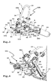
- the fastening device 16 is, for example, for attachment to a trailer coupling 82 (indicated in FIG FIG. 3 ) of the vehicle 80.
- the fastening device 16 comprises a clamping chamber or clamping receptacle 17, with which the fastening device 16 can be clamped to a ball head of the hitch 82 or any other fitting thereof.
- the clamp receptacle 17 can be opened and closed by means of a lever 18.
- the fastening device 16 is hidden, ie not visible, but also present.
- a support base 11f, 11g and 11h of the load carriers 10f, 10g and 10h is configured as a carriage 19f, 19g and 19h, which is slidably mounted on a vehicle-fixed guide base 20f, 20g and 20h, in the present case linearly displaceable, which of course also curved carriage guideways are possible, so that the carriage can extend, for example, to the rear top of the rear end 81 of the vehicle 80 and forward and downward (as seen in the direction of travel) in the direction of the interior of a load carrier receptacle 83 of the vehicle 80 inside.
- load carrier 10b When load carrier 10b is indicated that this may also be guided on a guide base which is fixed to the vehicle, such as a guide base 20b (dashed lines), in which the in this Case designed as a carriage support base 11 may be slidably mounted, for example linearly displaceable.
- a guide base which is fixed to the vehicle, such as a guide base 20b (dashed lines), in which the in this Case designed as a carriage support base 11 may be slidably mounted, for example linearly displaceable.
- the guide base 20b and 20f, 20g and 20h each have guide rails 21, on which the carriage 19f, 19g, 19h is guided.
- the side legs 13 of the support base 11f, 11g and 11h are designed as guide profiles or rails, which are guided displaceably on the guide rails 21.
- the side legs 13 may have a U-shape or an L-shape so that they can rest on the guide rails 21.
- the concrete design of the guide rails 21 and the side legs 13 is not important here, i. a different design of the profiles or rail shape is readily possible.
- 10a-10h is provided in all load carriers that they occupy a driving position when driving the vehicle 80, then when they are needed and a load is to be placed on them, while projecting in front of the rear end 81 of the vehicle 80.
- the drive concept according to the invention could, however, in principle also be used with roof racks, with carriers which can be fastened to a tailgate of a vehicle, or the like, as will become clear hereinafter.
- load carriers 10a-10e components shown partially only in the load carriers 10a-10e may of course also be present in the load carriers 10f-10h.
- load carriers 10f-10h components shown partially only in the load carriers 10a-10e may of course also be present in the load carriers 10f-10h.
- the specific embodiment insofar as, for example, adjustable carrier channels for setting up bicycles are shown, to be understood only as an example.
- the load carrier 10a-10h may also be provided for carrying, for example, transport boxes, transport platforms, collapsible transport boxes or the like. The comfortable operating concept is guaranteed in all cases:
- the load carriers 10a-10h each have at least one load-bearing member 22a-22h movable relative to its support base 11, 11f-11h and supported by a bearing assembly 23a-23h movable with respect to the support base 11, 11f-11h.
- the load-bearing parts 22a-22h can be handled comfortably, since they are in each case drivable following an innovative concept, in each case by means of a load-bearing part drive 24a-24h.
- the load-bearing parts 22a-22c and 22e-22g are in each case load attachments or carrying racks 25, which are provided overall for carrying a load.
- the carrying racks 25 can be used, for example, to park bicycles on them.
- the support racks 25 can each be adjusted as a whole by means of the load-carrying part drive 24a-24h, preferably between a use position G in which they are available for use of the respective load carrier, i. for applying a load, and a position hereinafter referred to as non-use position N, for example, intended for stowing the load carrier 10a-10h, but may also be a loading position occupying the load bearing member 22a-22h, e.g. to improve accessibility to the rear end 81 of the vehicle 80 or to facilitate loading of the load bearing member 22a-22h. In this loading position, for example, a tailgate of the vehicle 80 can be opened better or a luggage compartment is more accessible.
- the support frames 25 each comprise support legs 26, which are connected to one another via a connecting leg 27.
- the connecting leg 27 is designed, for example, as a license plate carrier or holds a license plate carrier 28.
- the connecting leg 27 and the support legs 26 form a U-shaped arrangement. Support when driving the vehicle 80 the base legs 12 of the support base 11 from the support legs 26.
- the connecting leg 27 and the base leg 12 are opposite each other.
- other frame designs may be selected.
- lights 29 may be arranged on the license plate carrier 28, for example.
- the lights 29 are pivotally mounted by means of pivot bearings 30 on the connecting leg 27, so that they are adjustable between the driving position shown in the drawing, in which they are substantially aligned with the license plate bracket 28 or parallel, and a non-use position, so that they close to the Support legs 26 are arranged.
- the lights 29 are arranged on the support frame 25 and not on the support base 11, which is of course conceivable.
- the support frame 25 supports pivotally and / or linearly and / or curved displaceable support troughs 31, which are intended for parking, for example, bicycles or other two-wheeled vehicles.
- the support troughs 31 are mounted by means of pivot bearings 32 pivotally mounted on the support legs 26 so that they are adjustable between the use position shown in the drawing and a provided in an interior space between the legs 26 non-use position or stowed position.
- a support 33 for supporting the load can be placed to the connecting legs 27 and away from this in a substantially upright position or angular position in which a load carrier is attachable to them.
- pivot bearings 34 are provided.
- a respective pivot bearing 34 can be fixed so that the respective position of the support 33 is fixed.
- the support 33 is designed, for example, in the form of a U-bracket or a V-bracket, i. it forms a retaining bracket 36.
- On the headband 36 for example, holding arms 37 for holding and supporting the load are present.
- the holding arms 37 have, for example, terminals with which a frame of a bicycle can be clamped.
- the support base 11 of the load carrier 10a forms a carriage guide base 38 on which the load bearing member 22a is slidably guided in the manner of a carriage.
- the side legs 13 guide rails on which the support legs 26 are mounted to move sliding in the manner of rails.
- the operator causes an adjustment by manual operation, so that the carriage or the load-bearing part 22 a between the in FIG. 1 illustrated driving position and a in FIG. 2 illustrated loading position L, which is comfortable for loading and unloading of the vehicle 80, is adjustable.
- the loading position L namely, a greater distance between the load bearing member 22 a, ie, for example, the headband 36, and the rear 81 is present, so that it is more easily accessible.
- a motor concept is chosen:
- the load bearing member drive 24a includes a motor 39a, which is attached to the support base 11, for example.
- the motor 39a is located in the interior 15 of the side leg 13.
- the motor 39a is provided with a drive gear 40a for driving the load bearing member 22a.
- the pinion 40a meshes, for example, with a toothed rail 41 on the load-bearing part 22a.
- the toothed rail 41 is arranged on the inner side of the carrying leg 26 facing the lateral leg 13, such that it can mesh with the pinion 40a.
- the motor 39a when running, it moves the toothed rail 41 back and forth linearly, so that thereby also the carriage or the load-carrying part 22a can be moved linearly between the driving position F and the loading position L.
- a curved sliding track is possible, for example, when the "guide rails", namely the side legs 13, have a curved course or have a curved guide track.
- a cable drive could be provided in which e.g. the motor 39a drives a cable disposed on the support base 11.
- the cable runs, for example, over deflection elements, e.g. Deflection rollers, at the longitudinal end portions of a side leg 13 to.
- the load-carrying part 22a At one run of the cable is e.g. the load-carrying part 22a, in the present case the support frame 25 is fixed and is thus taken along by the cable.
- a slot may be provided, through which a catch protrudes outward from the cable pull, preferably arranged in the interior of the profile part 14, for carrying the load-bearing part 22a.
- a load carrier part drive switch 42 is turned on.
- the switch 42 is located, for example, on one of the lights 29, ie at a far rear, remote from the rear end 81 of the load carrier 10a.
- the switch 42 is released, the carriage stops, which counteracts the risk of injury. Thus, so to speak, a "deadman" is present.
- the switch 42 may also effect a full displacement stroke, i. that, for example, the carriage moves completely into the driving position F or into the loading position L during a respective actuation of the switch 42.
- a tactile actuation may be configured so that the carriage each undergoes a reversal of motion when the switch 42 is actuated.
- bearing assemblies 23b, 23c are multi-joint arrangements and are similar in structure in that they can be described together below.
- the bearing assemblies 23b, 23c each include a steering lever 43 which is pivotally mounted by means of pivot bearings 44, 45 on the side legs 13 and the support leg 26.
- the steering lever 43 steers or controls a pivot-sliding movement of the support frame 25 with respect to the support base 11 b, 11 c, which takes place via a pivoting sliding bearing 46.
- the pivotal sliding bearing 46 includes, for example, a roller or a slider 47 at the front, free ends of the arm-like protruding side legs 13.
- the support legs 26 of the support frame 25 have a slot 48, in which these free ends and thus the role or the slider 47th can intervene.
- the connecting leg 27 as a whole, on the role or the slider 47 and makes not only a pivoting movement, in which the support frame 25 pivots backwards and downwards from the rear end 81, but also a sliding movement to the rear bottom, leaving the connecting leg 27 in one in FIG. 4 completely reached, in FIG. 3 not yet fully reached loading position L is closer to the ground.
- the space requirement of the support frame 25 is relatively small.
- Nachzutragen would still be that on the support legs 26 of course in a manner not shown support troughs 31 can be pivotally mounted.
- a pivot bearing 32 is shown.
- the load carrier drive 24b is arranged on the support frame 25. It includes a motor 39b, for example an electric motor, which drives or has a pinion 40b.
- the pinion 40b may, for example, mesh with a gear 49 which is non-rotatably mounted on the support base 11b.
- the motor 39b may be linearly displaceable along the direction of longitudinal extension of the support legs 26.
- a spring 50 ensures that the pinion 40b remains in positive contact with the gear 39.
- a motor 39 c of the load carrying member drive 24 c is arranged on the support base 11.
- the motor 39c is located in the interior of a side limb 13.
- the motor 39c drives a toothed rail 41 via a pinion 40c, which extends along the support leg 26, in particular in its interior.
- the pinion 40c meshes with the toothed rail 41 so that the toothed rail 41 is driven by rotating the motor 39c.
- the sliding movement is superimposed on a pivoting movement (because of the steering lever 43), so that the support leg 26 or the toothed rail 41 pivots about the pinion 40c.
- the pinion 40c thus forms, for example, a roller in the manner of the roller 47.
- each side leg 13 and support leg 26 each have a bearing assembly 23 b, 23 c including a steering lever 43 is present, which allows optimal storage.
- 26 may be present on one or both side legs 13 and support legs 26, a load carrier drive.
- a load-bearing part drive comprises a transmission element, for example a shaft 51, so that not only a pinion 40c, but also a further pinion or another gear part can be actuated by the motor 39c.
- a toothed rail 41 is then also arranged, for example, in the right support leg 26 in the drawing.
- the support 33 may be a load-bearing part driven according to the invention, which is motor-adjustable with respect to the load-bearing part 22b, 22c.
- the support 33 is on one or both pivot bearings 34 an e.g. an electric motor comprehensive load-bearing member drive 91 is provided, which can adjust the support 33 between the illustrated use position G and a to the support legs 26 out of adjustment non-use position N.
- load carrier drive 24d drives support troughs 31.
- load carrier drive 24d is a motor, namely a direct drive, which has a Drive shaft, not shown, which protrudes at its front sides in front of its housing, is rotatably connected to the support grooves 31 to adjust these between the utility position shown in the drawing and a 26 between the support legs in disguised non-use position.
- a linear drive (arrow x) could be provided which moves the support channels 31 linear.
- a cable drive is possible, which acts on one or more support troughs 31, e.g. unidirectional against the force of a spring arrangement, or bidirectional with oppositely effective cables.
- a controller 52 which shuts off, for example, the load carrier part drive 24d upon reaching a respective end position of the support channel 31.
- a safety function is useful in the controller 52.
- the controller 52 can detect whether a load has been deposited on the support channels 31. This is for example possible because the (electric) motor 39d is briefly energized. If the current flow is higher than that which is necessary only for adjusting the support troughs 31, the controller 52 determines therefrom that a load rests on the support troughs 31, that is to say on the load-bearing parts 22d.
- a load located there can be secured by means of straps 53, which are inserted into holders 54 and latched there preferably in the manner of a ratchet.
- the controller 52 not only to detect the rear area H of the load carrier 10d in the direction of travel, for example by means of distance sensors 55, but also the load area or the support area T of the load carrier 10d. If, for example, there is a load there, for example bicycles, the controller 52 does not permit pivoting or adjusting the support channels 31 or the load-bearing parts 22d.
- the present electrical load carrier drives 24a-24e are preferably powered by a vehicle electrical system 84 of the vehicle 80, i. with electricity, supplied.
- a vehicle electrical system 84 of the vehicle 80 i. with electricity, supplied.
- fluidic, such as pneumatic load carrier part drives would be possible, but this is not realized in the embodiments.
- a connector 56 of the load carrier 10d (in the other load carriers is also possible), plugged into a trailer socket 85 of the vehicle 80 to be supplied from there with power and expediently with control signals.
- the connector 56 is connected via a cable 57 to the controller 52 and this in turn, in a manner not shown electrically connected to the load bearing member drive 24d.
- the control signal that the controller 52 receives from the on-board network 84 may be, for example, a bus signal or a bus information from a vehicle-side bus, e.g. a CAN bus, act. For example, if it is signaled that the doors of the vehicle 80 are open (central locking open), this means that the vehicle 80 is at least at a corresponding programming of the vehicle 80. Then, for example, by a press of a switch 42 an operator 52, the controller to actuate the load carrier part drive 24d.
- a bus signal or a bus information from a vehicle-side bus e.g. a CAN bus
- An innovative operating concept can provide that, for example, by a predetermined actuation of the distance sensors 55, the control 52 receives an operating command to the load-carrying part drive 24d to operate or to supply power. If, for example, the distance sensors 55 are actuated with a predetermined operating sequence, for example by pivoting a hand in front of one or more of the distance sensors 55, the controller 52 controls the load-carrying part drive 24d for adjusting the support troughs 31 or the load-bearing parts 22d. Of course, this may also depend on a distance of the driving body relative to one or more of the distance sensors 55.
- a wireless operating concept is possible in which, for example, a transmitter 58 controls a receiver (not visible in the drawing) of the controller 52 by radio, ultrasound, infrared or in another way wirelessly to switch the load carrier part drive 24d.
- a transmitter 58 controls a receiver (not visible in the drawing) of the controller 52 by radio, ultrasound, infrared or in another way wirelessly to switch the load carrier part drive 24d.
- the distance sensors 55 can also be used to virtually block the controller 52.
- the controller 52 does not permit driving of the load carrying member drive 24d. Although this may still be unproblematic in the support channels 31.
- a carriage is moved, similar to the load carrier 10a, or a support frame 25 is moved as in the load carriers 10b and 10c, it is advantageous if the respective load carrier drive 24a-24d is only active in a driving sense, if no obstacle in the travel of the load bearing member is.
- a controller according to the invention and / or distance sensors used in the above type are expediently designed in such a way that that they block a driving of the load carrier drive only when there is an obstacle in the travel of the load bearing member, but not when a safe operation is possible.
- the load carrier 10e shows by way of example that a rotary direct drive is also possible.
- the load-bearing member drive 24e comprises, for example, an electric motor which drives directly in the pivot axis of the support frame 25 relative to the support base 11.
- the load-bearing part drive 24e may comprise, for example, a planetary gear, in particular a self-locking planetary gear. It is advantageous if between both side legs 13 and support legs 26 each have a motor 39e is present, so that the support frame 25 is not or only slightly twisted when swiveling in the non-use position or the working position.
- a linear drive 76 is possible, e.g. an electric spindle drive, a fluidic, in particular a pneumatic or hydraulic, lifting cylinder etc.
- the linear drive 76 is e.g. is linearly fixed with pivot bearings 77, but pivotally mounted on the load bearing member 22e and the support base 11.
- the load carrier 10e advantageously also has a controller 52 for controlling the load carrier drive 24e.
- the controller 52 is connected to the motors 39e via cables 60, for example.
- An advantageously present function indicator 59 e.g. a signal speaker 59a, a lighting means 59b or the like is active during the operation of the load carrying member drive 24e, so that an operator is warned by, for example, optical signals (lights), warning sounds or the like, so that he is in the motorized adjustment of Load bearing part 22e not injured.
- a holding device for holding the support frame 25, so the load-carrying part 22e, in the position of use G.
- the holding device 61 comprises a bolt 62, which in the position of use G in a receptacle 62 a, e.g. a hole, a hole or the like, engages the load-bearing part 22e.
- the latch 62 is spring loaded in its locking position.
- a holding drive 63 may be provided with the latch 62 can be moved into its locking position and / or its unlocked position.
- the controller 52 is suitably designed so that it first drives the holding device 61 for unlocking and then the load carrier drive 24e for driving, which prevents overheating.
- the holding device 61 is only an additional measure. Otherwise, it is very beneficial.
- controller 52 to drive the motors 39e, for example, periodically in the direction of the use position of the load-bearing part 22e, so as to ensure that the load-bearing part 22e or the carrying frame 25 is located on the support base 11 during a driving operation of the vehicle 80, in the present case, therefore, not pivoted backwards.
- Self-locking gears are also present in the load carrier part drives 24f and 24g of the load carriers 10f, 10g.
- load carrier part drives 24f, 24g each include a linear drive 64f, 64g.
- the linear drives 64f, 64g may be e.g.
- fluidic, in particular pneumatic cylinder include, in the embodiment, however, electric motors 39f, 39g, with which spindles 65f, 65g are driven.
- the spindles 65f, 65g can expediently extend out of or into a housing 90 of the motors 39f, 39g. In the interior of the housing 90 is not shown, for example, a driven by the motor 39f, 39g spindle nut.
- a pitch of the spindle 65 is preferably self-locking, so that a respective longitudinal position of the spindle 65f, 65g to the housing of the motor 39f, 39g is maintained even without energization of the motor 39f, 39g.
- the linear drives 64f, 64g are pivotally mounted on the load bearing part 22f, 22g by means of pivot bearings 66f, 66g. These are, for example, carrying racks 25, which are mounted pivotably by means of their bearing arrangements 23f, 23g on the support base 11f, 11g.
- the linear drives 64f, 64g are also pivotably mounted on the longitudinal end remote from the pivot bearing 66f, 66g, namely with pivot bearings 67f, 67g.
- the pivot bearing 67f is located on the support base 11f, for example on the base leg 12th or on one of the side legs 13.
- the pivot bearing 67g is fixed to the vehicle 80, in particular on a component of the load carrier 10g, for example, the guide base 20g stationary.
- the pivot bearing 67g is z. B. arranged on a cross member 78 between the guide rails 21.
- the load bearing member 22f pivots relative to the support base 11f.
- the pivot bearing 66f and the bearing assembly 23f are disposed on opposite longitudinal end portions of the load bearing member 22f.
- the load-bearing member drive 24g serves not only for adjusting the load-carrying part 22g between the use position G pivoted to the support base 11g or a loading position L displaced therefrom, which is indicated by dashed lines, but is also a support base drive 68 for adjusting the support base 11g between the in the load carrier receiver 83 into dislocated position N or the forward of the rear 81 vorverlini or moved out position, the in FIG. 8 is shown.
- the support base drive 68 extends, extends quasi, he pushes the carriage or the support base 11g first backwards outward in front of the rear 81. Then strikes the support base 11g, so the carriage to a stop 69.
- the linear drive 64f, 64g may expediently be telescopic.
- the linear drive 64g has a telescopic section 79.
- a drive according to the invention can also be a manual drive. So could e.g. the load carrier drive 24f be adjustable by means of a hand crank 92, a protruding handle or the like. An electric drive is then not necessary.
- a manual override can also be provided for an emergency operation of a motorized load-bearing member drive.
- Such a handle in the embodiment e.g. the crank handle 92 is expediently removable from the drive, in particular without tools, or adjustable to a non-use position, e.g. pivotable or hinged to the housing 79.
- Even with a manually actuable drive advantageous effects are present, e.g. a lower operating force and / or that an additional clamping or locking is unnecessary.
- a further exemplary embodiment for a support base drive 68 at the same time being able to form a load carrier part drive is shown schematically in the load carrier 10h.
- the support base 11h is extendable in the manner of a carriage.
- the support base drive 68 comprises, for example, a linear drive 64h.
- This linear drive 64h at the same time forms a load-carrying part drive 24h, which also includes a deflection gear 70.
- the deflection gear 70 comprises a ring gear 71, which is arranged at the bottom of the load-bearing part 22h. This is for example a headband in the manner of the retaining clip 36, a support or the like. Dashed is in FIG.
- the load-carrying part 22h pivots upward about an axis 73 of its bearing arrangement 23h, which is indicated by an arrow 74.
- the axis 73 is, for example, rotatably mounted on the support base 11, eg side legs thereof.
- the stopper 75 can thus at the same time form the function of a stop for the load-carrying part 22h, so that this on the one hand receives a force from the expediently a self-locking gear comprehensive load carrier drive 24h, on the other hand, the function of a stop for the carriage or the support base 11h as such.
- the carriage can therefore no longer be moved out of the load carrier receptacle 83 or away from the guide base 20h when the load carrying part 22h abuts the stop 75.
Landscapes
- Engineering & Computer Science (AREA)
- Mechanical Engineering (AREA)
- Lock And Its Accessories (AREA)
Priority Applications (1)
| Application Number | Priority Date | Filing Date | Title |
|---|---|---|---|
| EP13004329.2A EP2671757B1 (fr) | 2010-11-30 | 2011-11-28 | Support de charges avec un support fonctionnel |
Applications Claiming Priority (1)
| Application Number | Priority Date | Filing Date | Title |
|---|---|---|---|
| DE102010052773A DE102010052773A1 (de) | 2010-11-30 | 2010-11-30 | Lastenträger mit einem angetriebenen Lastentragteil |
Related Child Applications (2)
| Application Number | Title | Priority Date | Filing Date |
|---|---|---|---|
| EP13004329.2A Division EP2671757B1 (fr) | 2010-11-30 | 2011-11-28 | Support de charges avec un support fonctionnel |
| EP13004329.2 Division-Into | 2013-09-04 |
Publications (2)
| Publication Number | Publication Date |
|---|---|
| EP2457777A1 true EP2457777A1 (fr) | 2012-05-30 |
| EP2457777B1 EP2457777B1 (fr) | 2013-12-11 |
Family
ID=45370369
Family Applications (2)
| Application Number | Title | Priority Date | Filing Date |
|---|---|---|---|
| EP11009400.0A Active EP2457777B1 (fr) | 2010-11-30 | 2011-11-28 | Support de charges doté d'un élément de support de charges entraîné |
| EP13004329.2A Active EP2671757B1 (fr) | 2010-11-30 | 2011-11-28 | Support de charges avec un support fonctionnel |
Family Applications After (1)
| Application Number | Title | Priority Date | Filing Date |
|---|---|---|---|
| EP13004329.2A Active EP2671757B1 (fr) | 2010-11-30 | 2011-11-28 | Support de charges avec un support fonctionnel |
Country Status (2)
| Country | Link |
|---|---|
| EP (2) | EP2457777B1 (fr) |
| DE (1) | DE102010052773A1 (fr) |
Cited By (2)
| Publication number | Priority date | Publication date | Assignee | Title |
|---|---|---|---|---|
| EP2845770A1 (fr) * | 2013-09-10 | 2015-03-11 | WESTFALIA - Automotive GmbH | Support de charge pour un véhicule automobile doté de contours de serrage |
| WO2018069605A1 (fr) * | 2016-10-13 | 2018-04-19 | Psa Automobiles Sa | Support de velos escamotable sur attelage de vehicule |
Families Citing this family (4)
| Publication number | Priority date | Publication date | Assignee | Title |
|---|---|---|---|---|
| DE202012103182U1 (de) | 2012-08-22 | 2013-12-02 | Al-Ko Kober Se | Lastenträger |
| KR101684170B1 (ko) * | 2015-09-11 | 2016-12-08 | 현대자동차주식회사 | 차량용 자전거 캐리어 시스템 |
| CN113715740A (zh) | 2020-05-25 | 2021-11-30 | 杭州嘉迈机械有限公司 | 负载载架 |
| CN115339390A (zh) | 2021-05-12 | 2022-11-15 | 杭州嘉迈机械有限公司 | 承载架 |
Citations (5)
| Publication number | Priority date | Publication date | Assignee | Title |
|---|---|---|---|---|
| DE102004021709A1 (de) * | 2004-04-30 | 2005-12-08 | Cts Fahrzeug-Dachsysteme Gmbh | Ausziehbarer Fahrrad-Heckträger für Fahrzeuge, insbesondere Personenkraftwagen |
| US20070102465A1 (en) * | 2005-11-10 | 2007-05-10 | Magna Car Top Systems Gmbh | Load carrier for motor vehicles |
| EP1876060A2 (fr) * | 2006-07-08 | 2008-01-09 | Magna Car Top Systems GmbH | Dispositif de support pour au moins un vélo |
| DE202008017381U1 (de) * | 2008-11-07 | 2009-10-15 | Maucher, Eberhard, Dipl.-Ing. | Ausziehbarer Lastenträger, insbesondere zur Integration in die Heckseite eines Kraftfahrzeugs |
| EP2159106A1 (fr) * | 2008-08-29 | 2010-03-03 | Twinny Load B.V. | Porte-charge accoupable à un véhicule, par example un porte-cycle |
Family Cites Families (15)
| Publication number | Priority date | Publication date | Assignee | Title |
|---|---|---|---|---|
| US5884824A (en) * | 1996-07-23 | 1999-03-23 | Spring, Jr.; Joseph N. | Equipment transport rack for vehicles providing improved loading accessibility |
| DE29622310U1 (de) * | 1996-12-21 | 1997-02-13 | Reinhold Bernd | Transportbühne für Zweiräder, insbesondere Motorräder |
| DE19701231A1 (de) * | 1997-01-16 | 1998-07-23 | Metallwaren Heidersdorf Gmbh | Hebe- und Transportvorrichtung |
| DE10257903A1 (de) * | 2002-12-11 | 2004-06-24 | Webasto Vehicle Systems International Gmbh | Ausziehbarer Lastenträger |
| DE10308062A1 (de) * | 2003-02-26 | 2004-09-16 | Daimlerchrysler Ag | Heckgepäckträger für ein Kraftfahrzeug |
| DE10309327A1 (de) * | 2003-03-04 | 2004-10-07 | Bayerische Motoren Werke Ag | Gepäckträger an einem Kraftfahrzeug |
| US20080100426A1 (en) * | 2006-10-31 | 2008-05-01 | Master Lock Company Llc | Hitch mounted carrier alarm method |
| DE102007023495A1 (de) * | 2007-05-19 | 2008-11-20 | Uebler Gmbh | Lastenträger für ein Kraftfahrzeug |
| DE102007033855A1 (de) * | 2007-07-20 | 2008-02-21 | Daimler Ag | Fahrzeug mit Lastenträger |
| DE102007042769B4 (de) * | 2007-09-07 | 2022-10-06 | Westfalia-Automotive Gmbh | Lastenträger |
| NL1034946C1 (nl) * | 2008-01-24 | 2008-03-05 | Hermanus Gerhardus Joh Fischer | Fietsendrager met geïntegreerde hefinrichting voor montage op een trekhaak van een motorvoertuig. |
| DE102009060385A1 (de) * | 2009-05-27 | 2011-03-10 | Westfalia-Automotive Gmbh | Lastenträger mit einer Führungsschiene für einen Schlitten |
| DE102009057668A1 (de) * | 2009-12-09 | 2011-06-16 | Westfalia-Automotive Gmbh | Lastenträger mit einem Schlitten und einer Halteeinrichtung |
| DE102009057651A1 (de) * | 2009-12-09 | 2011-06-16 | Westfalia-Automotive Gmbh | Lastenträger mit einem Schlitten und einem Schlittenantrieb |
| DE102010010243A1 (de) * | 2010-03-03 | 2011-09-08 | Westfalia-Automotive Gmbh | Lastenträger mit einem Funktionsträger |
-
2010
- 2010-11-30 DE DE102010052773A patent/DE102010052773A1/de active Pending
-
2011
- 2011-11-28 EP EP11009400.0A patent/EP2457777B1/fr active Active
- 2011-11-28 EP EP13004329.2A patent/EP2671757B1/fr active Active
Patent Citations (5)
| Publication number | Priority date | Publication date | Assignee | Title |
|---|---|---|---|---|
| DE102004021709A1 (de) * | 2004-04-30 | 2005-12-08 | Cts Fahrzeug-Dachsysteme Gmbh | Ausziehbarer Fahrrad-Heckträger für Fahrzeuge, insbesondere Personenkraftwagen |
| US20070102465A1 (en) * | 2005-11-10 | 2007-05-10 | Magna Car Top Systems Gmbh | Load carrier for motor vehicles |
| EP1876060A2 (fr) * | 2006-07-08 | 2008-01-09 | Magna Car Top Systems GmbH | Dispositif de support pour au moins un vélo |
| EP2159106A1 (fr) * | 2008-08-29 | 2010-03-03 | Twinny Load B.V. | Porte-charge accoupable à un véhicule, par example un porte-cycle |
| DE202008017381U1 (de) * | 2008-11-07 | 2009-10-15 | Maucher, Eberhard, Dipl.-Ing. | Ausziehbarer Lastenträger, insbesondere zur Integration in die Heckseite eines Kraftfahrzeugs |
Cited By (3)
| Publication number | Priority date | Publication date | Assignee | Title |
|---|---|---|---|---|
| EP2845770A1 (fr) * | 2013-09-10 | 2015-03-11 | WESTFALIA - Automotive GmbH | Support de charge pour un véhicule automobile doté de contours de serrage |
| WO2018069605A1 (fr) * | 2016-10-13 | 2018-04-19 | Psa Automobiles Sa | Support de velos escamotable sur attelage de vehicule |
| FR3057512A1 (fr) * | 2016-10-13 | 2018-04-20 | Peugeot Citroen Automobiles Sa | Support de velos escamotable sur attelage de vehicule |
Also Published As
| Publication number | Publication date |
|---|---|
| EP2671757B1 (fr) | 2017-07-05 |
| DE102010052773A1 (de) | 2012-05-31 |
| EP2671757A1 (fr) | 2013-12-11 |
| EP2457777B1 (fr) | 2013-12-11 |
Similar Documents
| Publication | Publication Date | Title |
|---|---|---|
| EP2570305B1 (fr) | Support de charges doté d'un chariot et d'un entraînement de chariot | |
| EP2457777B1 (fr) | Support de charges doté d'un élément de support de charges entraîné | |
| EP1574394B1 (fr) | Unité fonctionelle pour l'habitacle d'un véhicule | |
| DE102005055625B4 (de) | Laderaumabdeckung für ein Fahrzeug | |
| EP2363323B1 (fr) | Support de charges avec un support fonctionnel | |
| DE102010052885B4 (de) | Lastenträger mit einer angetriebenen Befestigungseinrichtung | |
| EP2657051B2 (fr) | Agencement de couplage pour un support de toit | |
| DE1800784B2 (de) | Betätigungsmechanismus für eine Tür, vor altem für eine Schiebetür, eines Kraftfahrzeuges, insbesondere eines Taxi | |
| DE102006014561B3 (de) | Kraftfahrzeug | |
| DE202010017234U1 (de) | Lastenträger mit einem angetriebenen Lastentragteil | |
| EP2572938B1 (fr) | Support de charges doté d'un chariot et d'un dispositif de retenue | |
| DE102010045356A1 (de) | Lastenträger mit einem Schwenkschiebelager | |
| DE19622768C2 (de) | Bedienergeführtes Handhabungsgerät | |
| DE19927922A1 (de) | Vorrichtung zum Fixieren von Ladegut auf einer Ladefläche eines Fahrzeugs | |
| EP2363321B1 (fr) | Support de charges avec un support fonctionnel | |
| DE102007047349A1 (de) | Verladevorrichtung | |
| DE102017218943A1 (de) | Armlehne, Armlehnensystem und Fahrzeug | |
| DE102007046992B3 (de) | Bestattungsfahrzeug mit beweglichen Heckleuchten | |
| DE102008045770B4 (de) | Verwandelbare Karosserie eines Kraftfahrzeugs | |
| DE102017220198B3 (de) | Ladesystem, Kraftfahrzeug und Verfahren zum Verladen eines Elektrorollstuhls | |
| EP4046873A1 (fr) | Dispositif de support pour un véhicule automobile | |
| DE202007013832U1 (de) | Verladevorrichtung | |
| DE102010010245A1 (de) | Lastenträger mit einer beweglichen Stütze | |
| DE202007013834U1 (de) | Verladevorrichtung | |
| DE20311297U1 (de) | Fahrzeug mit Auszug |
Legal Events
| Date | Code | Title | Description |
|---|---|---|---|
| PUAI | Public reference made under article 153(3) epc to a published international application that has entered the european phase |
Free format text: ORIGINAL CODE: 0009012 |
|
| AK | Designated contracting states |
Kind code of ref document: A1 Designated state(s): AL AT BE BG CH CY CZ DE DK EE ES FI FR GB GR HR HU IE IS IT LI LT LU LV MC MK MT NL NO PL PT RO RS SE SI SK SM TR |
|
| AX | Request for extension of the european patent |
Extension state: BA ME |
|
| 17P | Request for examination filed |
Effective date: 20121121 |
|
| RIC1 | Information provided on ipc code assigned before grant |
Ipc: B60R 9/10 20060101ALI20130508BHEP Ipc: B60R 9/06 20060101AFI20130508BHEP |
|
| GRAP | Despatch of communication of intention to grant a patent |
Free format text: ORIGINAL CODE: EPIDOSNIGR1 |
|
| INTG | Intention to grant announced |
Effective date: 20130708 |
|
| GRAS | Grant fee paid |
Free format text: ORIGINAL CODE: EPIDOSNIGR3 |
|
| GRAA | (expected) grant |
Free format text: ORIGINAL CODE: 0009210 |
|
| AK | Designated contracting states |
Kind code of ref document: B1 Designated state(s): AL AT BE BG CH CY CZ DE DK EE ES FI FR GB GR HR HU IE IS IT LI LT LU LV MC MK MT NL NO PL PT RO RS SE SI SK SM TR |
|
| REG | Reference to a national code |
Ref country code: GB Ref legal event code: FG4D Free format text: NOT ENGLISH |
|
| REG | Reference to a national code |
Ref country code: CH Ref legal event code: EP |
|
| REG | Reference to a national code |
Ref country code: AT Ref legal event code: REF Ref document number: 644345 Country of ref document: AT Kind code of ref document: T Effective date: 20140115 |
|
| REG | Reference to a national code |
Ref country code: IE Ref legal event code: FG4D Free format text: LANGUAGE OF EP DOCUMENT: GERMAN |
|
| REG | Reference to a national code |
Ref country code: DE Ref legal event code: R096 Ref document number: 502011001776 Country of ref document: DE Effective date: 20140206 |
|
| REG | Reference to a national code |
Ref country code: NL Ref legal event code: VDEP Effective date: 20131211 |
|
| PG25 | Lapsed in a contracting state [announced via postgrant information from national office to epo] |
Ref country code: FI Free format text: LAPSE BECAUSE OF FAILURE TO SUBMIT A TRANSLATION OF THE DESCRIPTION OR TO PAY THE FEE WITHIN THE PRESCRIBED TIME-LIMIT Effective date: 20131211 Ref country code: HR Free format text: LAPSE BECAUSE OF FAILURE TO SUBMIT A TRANSLATION OF THE DESCRIPTION OR TO PAY THE FEE WITHIN THE PRESCRIBED TIME-LIMIT Effective date: 20131211 Ref country code: NL Free format text: LAPSE BECAUSE OF FAILURE TO SUBMIT A TRANSLATION OF THE DESCRIPTION OR TO PAY THE FEE WITHIN THE PRESCRIBED TIME-LIMIT Effective date: 20131211 Ref country code: NO Free format text: LAPSE BECAUSE OF FAILURE TO SUBMIT A TRANSLATION OF THE DESCRIPTION OR TO PAY THE FEE WITHIN THE PRESCRIBED TIME-LIMIT Effective date: 20140311 Ref country code: LT Free format text: LAPSE BECAUSE OF FAILURE TO SUBMIT A TRANSLATION OF THE DESCRIPTION OR TO PAY THE FEE WITHIN THE PRESCRIBED TIME-LIMIT Effective date: 20131211 Ref country code: SE Free format text: LAPSE BECAUSE OF FAILURE TO SUBMIT A TRANSLATION OF THE DESCRIPTION OR TO PAY THE FEE WITHIN THE PRESCRIBED TIME-LIMIT Effective date: 20131211 |
|
| REG | Reference to a national code |
Ref country code: LT Ref legal event code: MG4D |
|
| PG25 | Lapsed in a contracting state [announced via postgrant information from national office to epo] |
Ref country code: CY Free format text: LAPSE BECAUSE OF FAILURE TO SUBMIT A TRANSLATION OF THE DESCRIPTION OR TO PAY THE FEE WITHIN THE PRESCRIBED TIME-LIMIT Effective date: 20131211 Ref country code: RS Free format text: LAPSE BECAUSE OF FAILURE TO SUBMIT A TRANSLATION OF THE DESCRIPTION OR TO PAY THE FEE WITHIN THE PRESCRIBED TIME-LIMIT Effective date: 20131211 Ref country code: LV Free format text: LAPSE BECAUSE OF FAILURE TO SUBMIT A TRANSLATION OF THE DESCRIPTION OR TO PAY THE FEE WITHIN THE PRESCRIBED TIME-LIMIT Effective date: 20131211 |
|
| PG25 | Lapsed in a contracting state [announced via postgrant information from national office to epo] |
Ref country code: EE Free format text: LAPSE BECAUSE OF FAILURE TO SUBMIT A TRANSLATION OF THE DESCRIPTION OR TO PAY THE FEE WITHIN THE PRESCRIBED TIME-LIMIT Effective date: 20131211 Ref country code: IS Free format text: LAPSE BECAUSE OF FAILURE TO SUBMIT A TRANSLATION OF THE DESCRIPTION OR TO PAY THE FEE WITHIN THE PRESCRIBED TIME-LIMIT Effective date: 20140411 |
|
| PG25 | Lapsed in a contracting state [announced via postgrant information from national office to epo] |
Ref country code: PT Free format text: LAPSE BECAUSE OF FAILURE TO SUBMIT A TRANSLATION OF THE DESCRIPTION OR TO PAY THE FEE WITHIN THE PRESCRIBED TIME-LIMIT Effective date: 20140411 Ref country code: RO Free format text: LAPSE BECAUSE OF FAILURE TO SUBMIT A TRANSLATION OF THE DESCRIPTION OR TO PAY THE FEE WITHIN THE PRESCRIBED TIME-LIMIT Effective date: 20131211 Ref country code: CZ Free format text: LAPSE BECAUSE OF FAILURE TO SUBMIT A TRANSLATION OF THE DESCRIPTION OR TO PAY THE FEE WITHIN THE PRESCRIBED TIME-LIMIT Effective date: 20131211 Ref country code: SK Free format text: LAPSE BECAUSE OF FAILURE TO SUBMIT A TRANSLATION OF THE DESCRIPTION OR TO PAY THE FEE WITHIN THE PRESCRIBED TIME-LIMIT Effective date: 20131211 Ref country code: ES Free format text: LAPSE BECAUSE OF FAILURE TO SUBMIT A TRANSLATION OF THE DESCRIPTION OR TO PAY THE FEE WITHIN THE PRESCRIBED TIME-LIMIT Effective date: 20131211 Ref country code: PL Free format text: LAPSE BECAUSE OF FAILURE TO SUBMIT A TRANSLATION OF THE DESCRIPTION OR TO PAY THE FEE WITHIN THE PRESCRIBED TIME-LIMIT Effective date: 20131211 |
|
| REG | Reference to a national code |
Ref country code: DE Ref legal event code: R097 Ref document number: 502011001776 Country of ref document: DE |
|
| REG | Reference to a national code |
Ref country code: DE Ref legal event code: R082 Ref document number: 502011001776 Country of ref document: DE Representative=s name: BREGENZER, MICHAEL, DIPL.-ING., DE Ref country code: DE Ref legal event code: R082 Ref document number: 502011001776 Country of ref document: DE Representative=s name: PATENTANWAELTE BREGENZER UND REULE PARTNERSCHA, DE |
|
| PLBE | No opposition filed within time limit |
Free format text: ORIGINAL CODE: 0009261 |
|
| STAA | Information on the status of an ep patent application or granted ep patent |
Free format text: STATUS: NO OPPOSITION FILED WITHIN TIME LIMIT |
|
| PG25 | Lapsed in a contracting state [announced via postgrant information from national office to epo] |
Ref country code: DK Free format text: LAPSE BECAUSE OF FAILURE TO SUBMIT A TRANSLATION OF THE DESCRIPTION OR TO PAY THE FEE WITHIN THE PRESCRIBED TIME-LIMIT Effective date: 20131211 |
|
| 26N | No opposition filed |
Effective date: 20140912 |
|
| REG | Reference to a national code |
Ref country code: DE Ref legal event code: R082 Ref document number: 502011001776 Country of ref document: DE Representative=s name: PATENTANWAELTE BREGENZER UND REULE PARTNERSCHA, DE |
|
| REG | Reference to a national code |
Ref country code: DE Ref legal event code: R097 Ref document number: 502011001776 Country of ref document: DE Effective date: 20140912 |
|
| PG25 | Lapsed in a contracting state [announced via postgrant information from national office to epo] |
Ref country code: SI Free format text: LAPSE BECAUSE OF FAILURE TO SUBMIT A TRANSLATION OF THE DESCRIPTION OR TO PAY THE FEE WITHIN THE PRESCRIBED TIME-LIMIT Effective date: 20131211 |
|
| PG25 | Lapsed in a contracting state [announced via postgrant information from national office to epo] |
Ref country code: BE Free format text: LAPSE BECAUSE OF NON-PAYMENT OF DUE FEES Effective date: 20141130 Ref country code: LU Free format text: LAPSE BECAUSE OF FAILURE TO SUBMIT A TRANSLATION OF THE DESCRIPTION OR TO PAY THE FEE WITHIN THE PRESCRIBED TIME-LIMIT Effective date: 20141128 Ref country code: MC Free format text: LAPSE BECAUSE OF FAILURE TO SUBMIT A TRANSLATION OF THE DESCRIPTION OR TO PAY THE FEE WITHIN THE PRESCRIBED TIME-LIMIT Effective date: 20131211 |
|
| REG | Reference to a national code |
Ref country code: CH Ref legal event code: PL |
|
| PG25 | Lapsed in a contracting state [announced via postgrant information from national office to epo] |
Ref country code: LI Free format text: LAPSE BECAUSE OF NON-PAYMENT OF DUE FEES Effective date: 20141130 Ref country code: CH Free format text: LAPSE BECAUSE OF NON-PAYMENT OF DUE FEES Effective date: 20141130 |
|
| REG | Reference to a national code |
Ref country code: IE Ref legal event code: MM4A |
|
| REG | Reference to a national code |
Ref country code: FR Ref legal event code: PLFP Year of fee payment: 5 |
|
| PG25 | Lapsed in a contracting state [announced via postgrant information from national office to epo] |
Ref country code: IE Free format text: LAPSE BECAUSE OF NON-PAYMENT OF DUE FEES Effective date: 20141128 |
|
| PG25 | Lapsed in a contracting state [announced via postgrant information from national office to epo] |
Ref country code: SM Free format text: LAPSE BECAUSE OF FAILURE TO SUBMIT A TRANSLATION OF THE DESCRIPTION OR TO PAY THE FEE WITHIN THE PRESCRIBED TIME-LIMIT Effective date: 20131211 |
|
| PG25 | Lapsed in a contracting state [announced via postgrant information from national office to epo] |
Ref country code: GR Free format text: LAPSE BECAUSE OF FAILURE TO SUBMIT A TRANSLATION OF THE DESCRIPTION OR TO PAY THE FEE WITHIN THE PRESCRIBED TIME-LIMIT Effective date: 20140312 Ref country code: BG Free format text: LAPSE BECAUSE OF FAILURE TO SUBMIT A TRANSLATION OF THE DESCRIPTION OR TO PAY THE FEE WITHIN THE PRESCRIBED TIME-LIMIT Effective date: 20131211 Ref country code: IT Free format text: LAPSE BECAUSE OF FAILURE TO SUBMIT A TRANSLATION OF THE DESCRIPTION OR TO PAY THE FEE WITHIN THE PRESCRIBED TIME-LIMIT Effective date: 20131211 |
|
| GBPC | Gb: european patent ceased through non-payment of renewal fee |
Effective date: 20151128 |
|
| PG25 | Lapsed in a contracting state [announced via postgrant information from national office to epo] |
Ref country code: HU Free format text: LAPSE BECAUSE OF FAILURE TO SUBMIT A TRANSLATION OF THE DESCRIPTION OR TO PAY THE FEE WITHIN THE PRESCRIBED TIME-LIMIT; INVALID AB INITIO Effective date: 20111128 Ref country code: TR Free format text: LAPSE BECAUSE OF FAILURE TO SUBMIT A TRANSLATION OF THE DESCRIPTION OR TO PAY THE FEE WITHIN THE PRESCRIBED TIME-LIMIT Effective date: 20131211 Ref country code: MT Free format text: LAPSE BECAUSE OF FAILURE TO SUBMIT A TRANSLATION OF THE DESCRIPTION OR TO PAY THE FEE WITHIN THE PRESCRIBED TIME-LIMIT Effective date: 20131211 |
|
| REG | Reference to a national code |
Ref country code: FR Ref legal event code: PLFP Year of fee payment: 6 |
|
| PG25 | Lapsed in a contracting state [announced via postgrant information from national office to epo] |
Ref country code: GB Free format text: LAPSE BECAUSE OF NON-PAYMENT OF DUE FEES Effective date: 20151128 |
|
| REG | Reference to a national code |
Ref country code: FR Ref legal event code: PLFP Year of fee payment: 7 |
|
| REG | Reference to a national code |
Ref country code: AT Ref legal event code: MM01 Ref document number: 644345 Country of ref document: AT Kind code of ref document: T Effective date: 20161128 |
|
| PG25 | Lapsed in a contracting state [announced via postgrant information from national office to epo] |
Ref country code: AT Free format text: LAPSE BECAUSE OF NON-PAYMENT OF DUE FEES Effective date: 20161128 |
|
| PG25 | Lapsed in a contracting state [announced via postgrant information from national office to epo] |
Ref country code: MK Free format text: LAPSE BECAUSE OF FAILURE TO SUBMIT A TRANSLATION OF THE DESCRIPTION OR TO PAY THE FEE WITHIN THE PRESCRIBED TIME-LIMIT Effective date: 20131211 |
|
| REG | Reference to a national code |
Ref country code: FR Ref legal event code: PLFP Year of fee payment: 8 |
|
| PG25 | Lapsed in a contracting state [announced via postgrant information from national office to epo] |
Ref country code: AL Free format text: LAPSE BECAUSE OF FAILURE TO SUBMIT A TRANSLATION OF THE DESCRIPTION OR TO PAY THE FEE WITHIN THE PRESCRIBED TIME-LIMIT Effective date: 20131211 |
|
| PGFP | Annual fee paid to national office [announced via postgrant information from national office to epo] |
Ref country code: FR Payment date: 20211011 Year of fee payment: 11 |
|
| PG25 | Lapsed in a contracting state [announced via postgrant information from national office to epo] |
Ref country code: FR Free format text: LAPSE BECAUSE OF NON-PAYMENT OF DUE FEES Effective date: 20221130 |
|
| PGFP | Annual fee paid to national office [announced via postgrant information from national office to epo] |
Ref country code: DE Payment date: 20231129 Year of fee payment: 13 |